

Page 1

Introduction
SCE170
To the owner or user: This service manual is
intended to provide you, and the maintenance or
service technician, with the information needed to
install, start up, clean, maintain and repair this
product.
The SCE170 is an ice machine that produces
cubed ice on a grid type freezing surface. The
cubes form into a cluster that falls into the ice
storage bin where they break up into individual
and small groups of cubes.
The SCE170 automatically maintains the level of
ice by turning on when the ice level falls, and
switches off when the bin is full.
This unit is serviceable in place; the ice storage bin
and hood may be removed from the chassis to
allow service access without removing the ice
machine from its installed position. The
refrigeration system uses HP62 as the refrigerant.
Table of Contents
Specifications . . . . . . . . . . . . . . . . . . . . . . . . . . . . . . . . . . . . . . . . . . . 2
For The Installer: Environmental Limitations . . . . . . . . . . . . . . . . . . . . . . . . . . . 3
Installation . . . . . . . . . . . . . . . . . . . . . . . . . . . . . . . . . . . . . . . . . . . . . 4
Removal of the Cabinet . . . . . . . . . . . . . . . . . . . . . . . . . . . . . . . . . . . . . . 7
Component Location . . . . . . . . . . . . . . . . . . . . . . . . . . . . . . . . . . . . . . . 8
Component Description . . . . . . . . . . . . . . . . . . . . . . . . . . . . . . . . . . . . . . 9
Initial Start Up . . . . . . . . . . . . . . . . . . . . . . . . . . . . . . . . . . . . . . . . . . . 10
Electrical Sequence . . . . . . . . . . . . . . . . . . . . . . . . . . . . . . . . . . . . . . . . 12
Maintenance and Cleaning . . . . . . . . . . . . . . . . . . . . . . . . . . . . . . . . . . . . 13
Sanitzing and Water System Cleaning . . . . . . . . . . . . . . . . . . . . . . . . . . . . . . 14
Maintenance and Cleaning . . . . . . . . . . . . . . . . . . . . . . . . . . . . . . . . . . . . 15
Water Schematic: . . . . . . . . . . . . . . . . . . . . . . . . . . . . . . . . . . . . . . . . . 16
Refrigeration Schematic: . . . . . . . . . . . . . . . . . . . . . . . . . . . . . . . . . . . . . 17
Technical Characteristics . . . . . . . . . . . . . . . . . . . . . . . . . . . . . . . . . . . . . 18
Service Diagnosis . . . . . . . . . . . . . . . . . . . . . . . . . . . . . . . . . . . . . . . . 19
Removal and Replacement: Cube Size Control . . . . . . . . . . . . . . . . . . . . . . . . . 22
Removal and Replacement: Water Pump . . . . . . . . . . . . . . . . . . . . . . . . . . . . 23
Removal and Replacement: Float Valve . . . . . . . . . . . . . . . . . . . . . . . . . . . . . 24
Removal and Replacement: Curtain & Bin Control . . . . . . . . . . . . . . . . . . . . . . . . 25
Removal and Replacement: Purge Valve . . . . . . . . . . . . . . . . . . . . . . . . . . . . . 26
Refrigeration System Service: HP62 . . . . . . . . . . . . . . . . . . . . . . . . . . . . . . . 28
Parts lists and wiring diagrams are located in
the center of this manual, printed on yellow
paper .
6JKUOCPWCNYCURTKPVGFQPTGE[ENGFRCRGT
October 1998
Page 1
Page 2
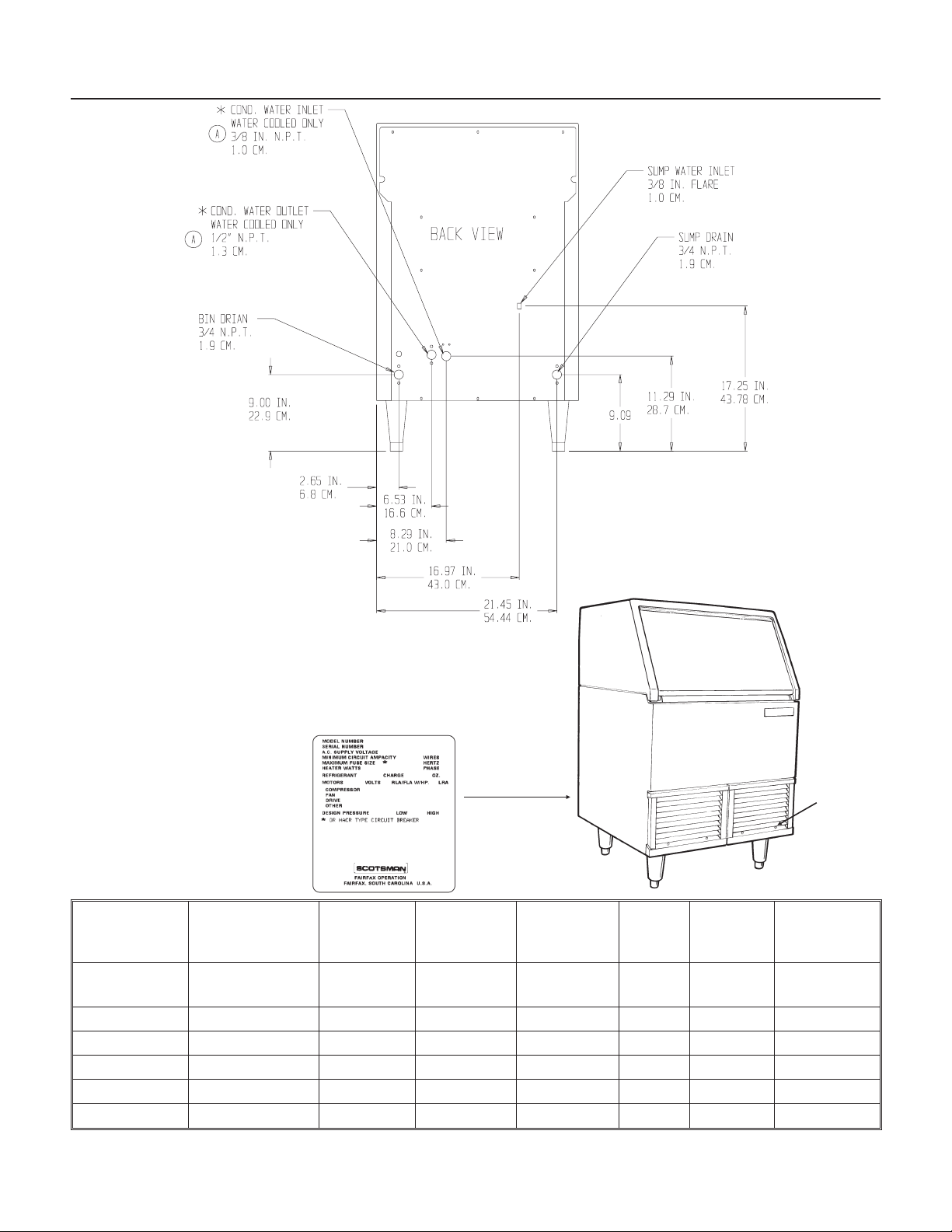
SCE170
Specifications
The unit is equipped with an electrical power
cord, but should only be plugged into a circuit
dedicated to the ice machine.
THE NAMEPLATE IS LOCATED
ON THE BACK PANEL.
A SERIAL NUMBER PLATE IS
LOCATED BEHIND THE RIGHT
FRONT PANEL, ON THE BASE IN
FRONT OF THE CONTROL BOX
Model
Number
SCE170A-1A
SCE170A-1C SAME SAME SAME Air 10 see page 18
SCE170W-1A SAME SAME SAME Water 10 see page 18
SCE170W-1C SAME SAME SAME Water 10 see page 18
SCE170A-6C same 230/50/1 SAME Air 5 1150 see page 18
SCE170W-6C same 230/50/1 SAME Water 5 1150 see page 18
Note: A scoop and legs are included. Power Cord Supplied.
Dimensions
(w/o) legs
H" x W" x D"
1
33 x 24
⁄4x24
Basic
Electrical
115/60/1 “Half-Dice”
Ice Type Condenser
Cube
June 2002
Page 2
Total
Type
Air 10 see page 18
Load
Amps
Total
Wattage
Refrigerant
HP62
(R-404a)
Serial
Number
Plate
(Behind Grill)
Page 3
For The Installer: Environmental Limitations
The ice machine must be installed indoors in a
controlled environment.
Minimum Maximum
Air Temp 50
Water Temp 40
Water Pressure 20 PSI 80 PSI
Volt age 103.5 126.5
0
F. 1000F.
0
F. 1000F.
SCE170
Air Out
Operating the ice machine outside of the above
limitations, or outdoors, is potentially damaging to
the machine, and it is misuse of the machine. This
may void the warranty.
Scotsman Ice Systems are designed and
manufactured with the highest regard for safety
and performance. They meet or exceed the
standards of UL, NSF, and CSA.
Scotsman assumes no liability or responsibility of
any kind for products manufactured by Scotsman
that have been altered in any way, including the
use of any part and/or other components not
specifically approved by Scotsman.
Scotsman reserves the right to make design
changes and/or improvements at any time.
Specifications and design are subject to change
without notice.
October 1998
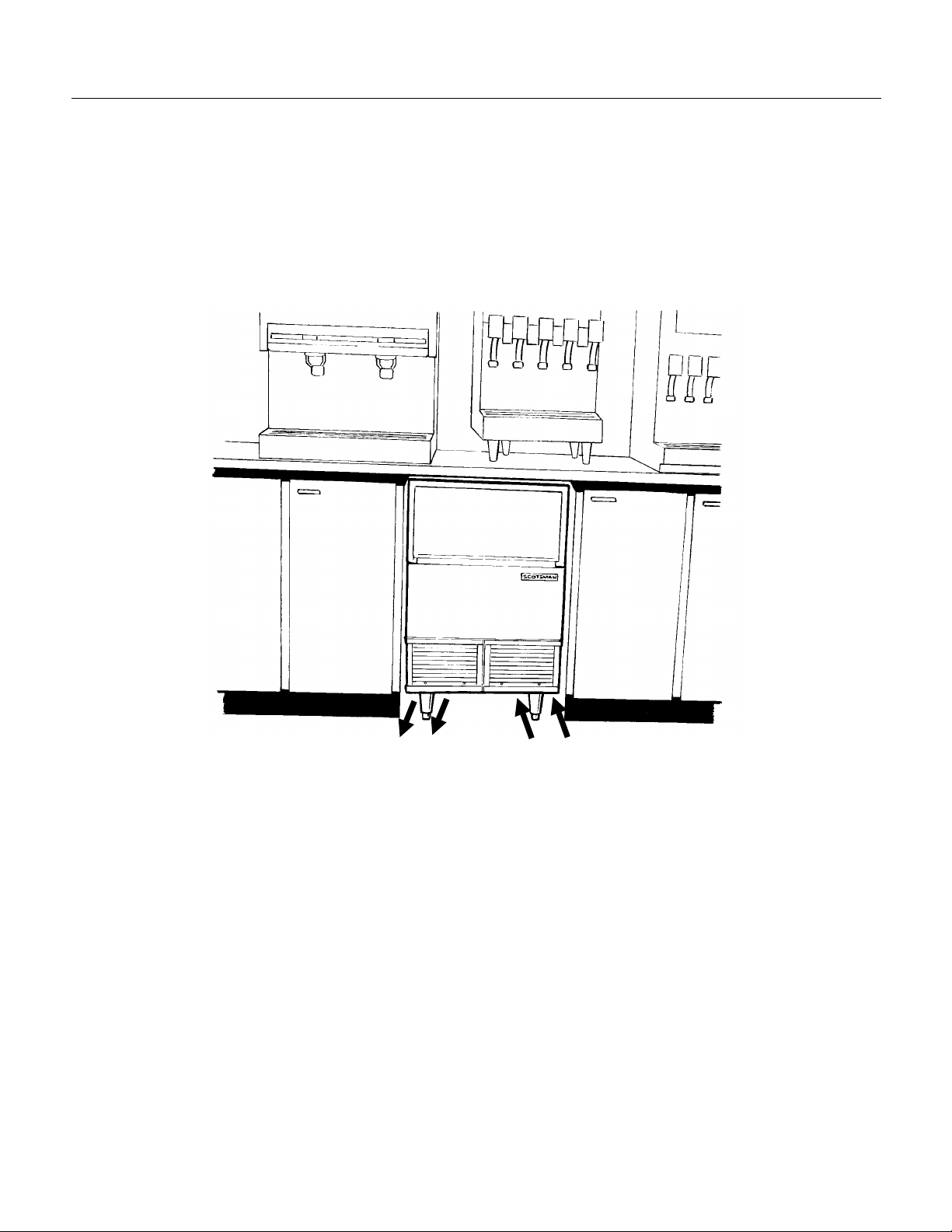
Air In
Airflow on air cooled models is:
Intake through the right front grill.
•
Exhaust through the left front grill.
•
Do not install where this air flow is obstructed.
The SCE170 has a removable cabinet. When
installed, the machine should have some extra
clearance (
the cabinet may be easily removed when the
machine is in place.
Page 3
1
") on the left and right sides so that
⁄
8
Page 4

SCE170
Installation
Water
The water supply for this ice machine has been in
contact with many materials since it fell from the
sky as rain. All rain is slightly acidic, and tends to
dissolve the materials it comes in contact with.
During water’s journey to the ice machine, it has
flowed over and through the ground, been picked
up by a municipal or private pump, forced through
a series of pipes of differing construct ion and may
have been treated by the municipality providing
the water.
The water supplied to this ice machine will then
contain a variety of substances that will likely show
up as solids during the ice making process. These
solids are similar to those found when water is
boiled out of a saucepan. Only the water boils
away, and the minerals that were in the water
solidify in the pan. During ice making only the
water is frozen into ice, the minerals stay behind in
the reservoir. This machine pumps out the water in
the reservoir every cycle to minimize the amount of
minerals in the water system, but after time the
minerals will appear and have to be dissolved by
ice machine cleaner , t hen f l ushed away dur ing t he
cleaning process.
An ice machine is a food manufacturing plant; it
takes a raw material, in this case water, and
transforms it into a food product, ice. The purit y of
the water is very important in obtaining pure ice
and in maximizing product life.
The water to the ice machine should be filtered.
Water filters vary greatly in ability and function.
Install one that filters out suspended solids to a
dimension of 5 microns or less. The finer the filter
the better, but finer filters may plug-up sooner than
course ones. It may be necessary to add a course
filter ahead of the fine filter to prolong f ilt er lif e.
This ice machine may be installed in the open or
under a counter. No clearance is required at the
sides or top beyond what’s needed to place the
cabinet into position. Air cooled models blow air in
and out through the grills at the front. Space is
required for utility connections at the back.
The ice machine is not designed for outdoor
use. It must be installed indoors, in a
controlled environment. The air and water
temperatures must not exceed rated limits.
Electrical power is supplied through a cord
connected to the unit. All local codes must be
followed.
Pre-installation:
1. Inspect the place where the ice machine is to be
installed. Check for:
space for the cabinet,
•
water supply,
•
drain availability
•
and electrical power supply.
•
No extension cords are allowed. The building drain
inlet must be lower than the drain outlets at the
back of the ice machine. The water supply must
have a hand shut off valve accessible when the
unit is installed.
2. Determine the method of installation, is the
machine to be installed under the counter? Is the
drain in the floor under the machine? Is the water
inlet valve accessible?
Have the water tested. Acidic water or alkaline
water will both cause corrosion. Dissolved solids
cannot be filtered out. Check with a water
treatment specialist regarding testing, treatment
and filters.
October 1998
Page 4
Page 5
Installation
SCE170
For The Plumber
1. Connect cold potable water to the
3
" male flare
⁄
8
at the top back of the cabinet. A water filter is
recommended. Flush the water line prior to
connecting to the ice machine.
If water cooled, connect a separate water inlet line
to the water cooled condenser inlet fitting. It should
also have a hand shut off valve.
A loop of copper t ubing may be used bet ween t he
ice machine and the water supply. This will allow
the ice machine to be pulled out from its installed
location without disconnecting the water line. No
back-flow preventer should be needed in the inlet
potable water line because provision for that is
incorporated in this N.S.F. listed product (the float
seat is above the reservoir wall and cannot siphon).
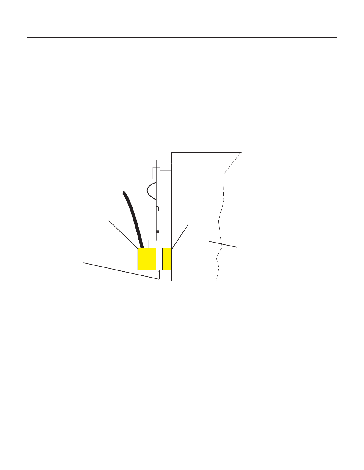
2. Connect a drain tube to each drain. The drain
tubes from these connections must be run
separately. There are two connections at the
back of the cabinet,
one is the bin drain
and the other is the
purge drain. Both
3
are
" F.P.T. brass
⁄
4
fittings.
Bin Drain
Vent
Drain tube material must be rigid and meet local
code.
Traps in the bin drain line without vent s ahead of
them will cause poor draining.
The bin drain must be vented if there is a long
horizontal run (5’ or more). The purge drain
must also be vented.
All drains are gravity, and
must have a minimum fall of 1/4" per foot of
horizontal run. The water cooled condenser drain
should not be vented, and is routed separately.
Maintain the air gap required by local code
between the end of the drain tubes and the
building drain receptacle.
Note: Drain tubing should be insulated to prevent
condensation from forming on the tubing.
CONFORM TO ALL LOCAL CODES
Note: The unit is designed for drain connections
on the outside of the cabinet. To connect the
drains inside would require the removal of the
drain fittings attached to the back panel, and field
fabricated drain tubes routed inside the base of the
unit.
Purge Valve
Drain Vent
Bin Drain
Floor Drain
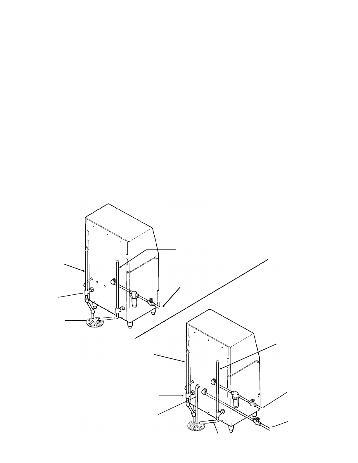
Air Cooled
Plumbing
Connections
Note: Recommended
Drain Vent Vertical
Tube Length is 24"
Bin Drain
Vent
Bin Drain
Condenser Drain
Potable Water
Inlet
October 1998
Page 5
Water Cooled
Plumbing
Connections
Purge Valve
Drain Vent
Potable
Water Inlet
Condenser Water
Inlet
Purge Drain
Page 6

SCE170
Installation
For The Electrician
This is a cord-connected unit, and must be on a
separate 115 volt AC 60 cycle single phase power
supply. The maximum fuse size for this circuit
should be 15 amps, per the nameplate use fuses,
or HACR circuit breakers.
Follow All Local Codes - This Unit Must Be
Grounded.
disable or by-pass ground prong on electrical plug.
1. Level the cabinet, use the leg levelers on the
end of the legs to adjust the cabinet height. (Legs
should have been installed when the unit was
unpacked).
2. Wash out the bin and hood. I f desir ed, t he
interior of the bin could be sanitized.
Do not use extension cords and do not
After Utility Connections:
3. Locate the scoop, wash it and have it available
for use when needed.
Final Check List
1. Is the ice maker cabinet in a room where
ambient temperatures are within the minimum and
maximum temperatures specified?
2. Has the water supply been connected?
3. Is the water pressure adequate?
4. Have the water connections been checked for
water leaks?
5. Have the drain connections been made?
6. Have the drain connections been checked for
leaks?
7. Is the cabinet level?
8. Is the ice machine plugged into a 115 volt
electrical power supply and is the ice machine the
only load on that circuit?
9. Has all of the shipping material been removed
from the inside of the cabinet?
10. Has the bin and cabinet been wiped clean and
sanitized?
11. Has the Customer Evaluation & Warranty
Registration form been filled out? Check for correct
model and serial numbers from the nameplate,
then mail the completed form to Scotsman.
12. Has the owner/user been given the name and
telephone number of the authorized Scotsman
Service Agency serving that location?
13. To start up machine, follow the directions on
page 10. For more information on the unit, t ur n t o
the next page.
October 1998
Page 6
Page 7
Removal of the Cabinet
SCE170
One of the most useful features of this ice machine
is the ability to remove the cabinet from the ice
machine without removing the ice machine from its
installed position.
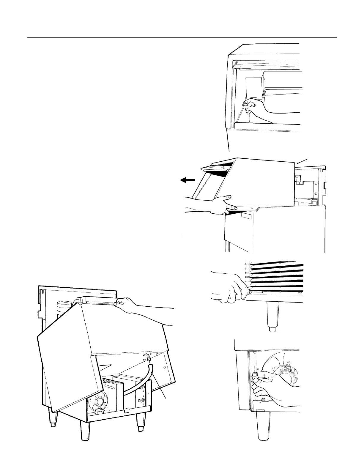
To Remove:
1. Switch the master switch to OFF. Be certain the
ice machine has been switched off.
2. Open the bin door and unscrew the knobs at the
left and right inside of the ice storage bin. Unscrew
the knobs all the way out.
3. Pull the hood and door assembly straight out
until it can be lifted up. Caution: the door will be
free to come out the back of the hood when
removed from the cabinet base.
4. To remove the cabinet base the hood must be
removed first.
5. Remove 4 screws and the two grills at the front
of the base.
6. In the area exposed when the grills are removed
are two knobs similar to those removed in step 2.
Unscrew and remove the two knobs.
STEP 2
STEP 3
Hood
7. Locate bin drain. Loosen hose clamp holding
drain tube to fitting and pull the drain tube off of the
fitting.
8. Lift up the front of the base and rotate the base
up and off of the ice machine.
The machine is now exposed for service.
STEP 8
STEP 5
STEP 6
Bin Drain
October 1998
Page 7
Page 8
SCE170
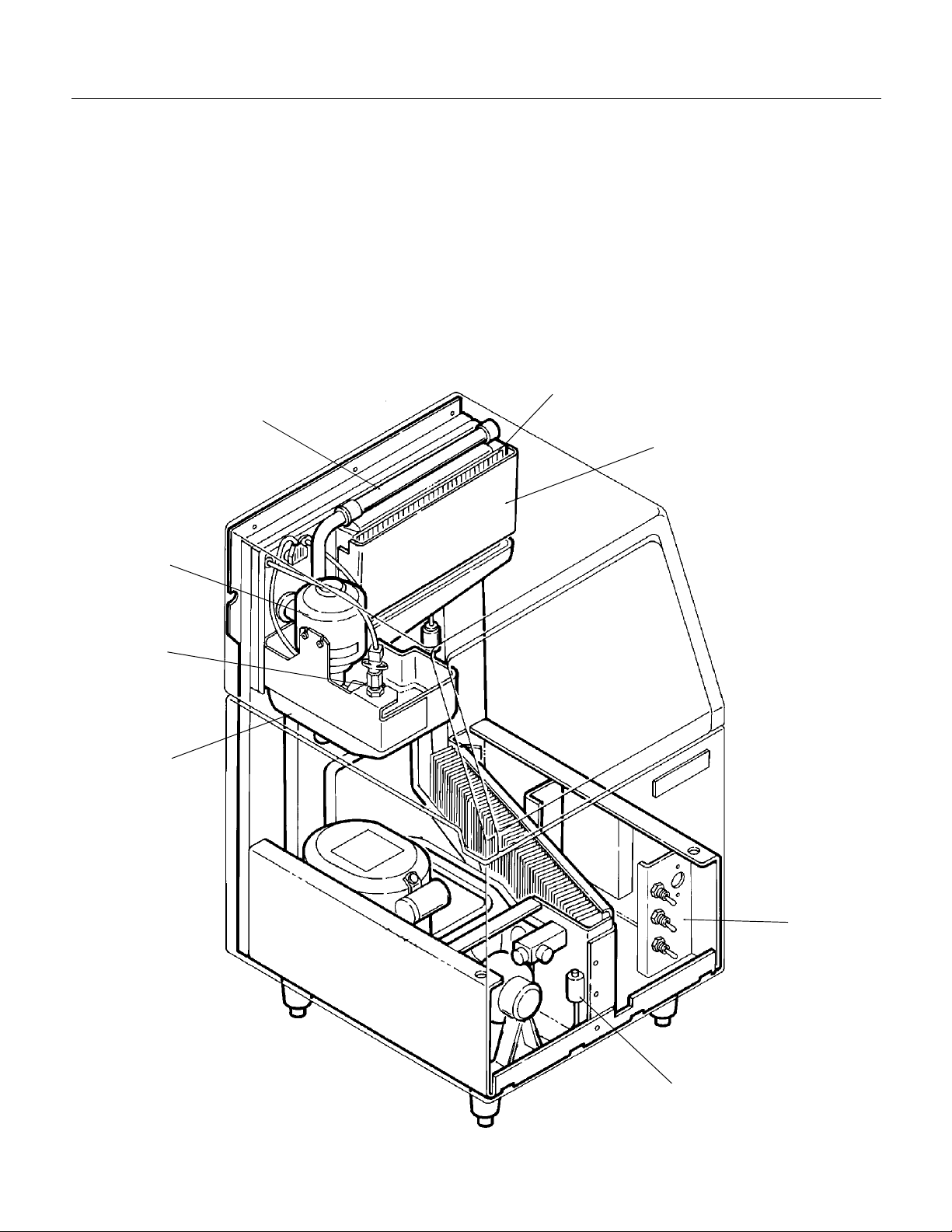
Component Location
The ice machine is designed for front service.
Many components are serviceable from the front
without removing the cabinet. With the cabinet
removed, nearly all components are serviceable.
In the bin area can be found:
Water pump
•
Float valve
•
Reservoir
•
Evaporator
•
Curtain
•
Water distributor
•
Water Distributor
Water Pump
Behind the right front grill on the front edge of the
control box:
Control box with cube size control adjustment
•
ON/OFF/CLEAN switch
•
Manual Harvest switch
•
Purge switch
•
Inside the control box is control system for the ice
machine.
When the bin is removed, the condensing unit is
visible.
Evaporator
Curtain
Float Valve
Reservoir
Component Location
Control
Box
Hi Pressure Cut
Out Switch
October 1998
Page 8
Page 9

Component Description
SCE170
Water Pump
During the freeze cycle, the water pump moves the
water from the reservoir to the water distributor at
the top of the evaporator. During the harvest
cycle, the water pump moves water from the
reservoir to the purge valve and down the drain.
Float
The float valve controls the water flow into the
reservoir. When the water level drops in the
reservoir, the float also drops and opens the valve.
Note: water flow to this ice machine is controlled
by a flow control within the float valve.
Shut Off Valve
There is a water shut off valve located just above
the float valve. Pushing the valve button controls
the water flow to the float valve.
Reservoir
The place where the water pump picks up water to
pump, and a return trough for water flowing from
the evaporator.
Curtain
There is a curtain to cover the ice making side of
the evaporator. The curtain keeps water from
flowing into the ice storage bin, and, through the
curtain sensor, controls the harvest time and on/off
operation of the ice machine. There are two
indicator lights for the curtain on the control board.
Both lights will be ON when the curtain is fully
closed.
Note: If the unit is in the Freeze Cycle, the Curtain
can be moved/removed without disturbing the
operation of the machine.
Water Distributor
The water distributor is an assembly of two tubes
(one inside the other) that evenly distributes water
over the evaporator.
Purge Valve
The purge valve opens during the harvest cycle,
allowing the water pump to pump reservoir water
down the drain. This dilutes the reservoir’s
concentration of minerals that remain after water is
made into ice.
High Pressure Cut Out
This is a switch that opens to stop the ice machine
when the internal refrigeration pressures become
too high (over 450 PSIG). It is a manual reset on
all water cooled machines and all air cooled
machines built prior to October 1998, after that t he
air cooled models use an automatic reset switch.
ON/OFF/CLEAN Switch
This switch is the main manual control for the ice
machine.
Purge Switch
This switch operates the purge valve ONLY when
the ON/OFF/CLEAN switch is in the Clean
position. Used when cleaning the ice machine.
Manual Harvest Switch
This switch puts the machine into the harvest
cycle, used when cleaning or servicing the
machine.
Cube Size Control
The cube size control is a reverse-acting
thermostat the controls the start of t he t i med
freeze cycle. It must be set properly to provide the
correct size cube bridge. When it is Closed, an
indicator light on the control board will be ON.
Strainer
There is a strainer in the inlet water line to keep
large particles that may be in the water supply
from plugging up the float valve. The strainer may
be cleaned if it becomes restricted.
Hot Gas Valve
The hot gas valve is a refrigeration component
used to by-pass the condenser and force warm
refrigerant into the evaporator during t he har vest
cycle.
Evaporator
Where the ice is formed. It is a vertical, 5 row by
26 column, all copper , nickel-plated evaporator.
The outside edges of the evaporator are enclosed
in plastic to keep water out.
Thermostatic Expansion Valve
The thermostatic expansion valve is used to meter
liquid refrigerant into the evaporator, adjusting the
flow of refrigerant as required to make ice.
October 1998
Page 9
Page 10
SCE170
Initial Start Up
After the final check list has been gone through,
the ice machine may be started up.
1. Open the bin door, open the water shut off valve
and watch the reservoir fill with water. The water
level should be about 1 5/8" from the top front
edge of the reservoir when the valve shuts off.
Adjust water level only if more than 1/4" off normal.
2. Pull open and release the curtain to check that it
moves freely and closes completely. Check that bin
control sensor is in line with the magnet in the
curtain. Reposition curtain and/or sensor to their
normal positions to bring these two components in
line.
Front View of Left End of Curtain
Bin
Control
Sensor
8. The water temperature in the reservoir will soon
o
be 32
evaporator. Note: In most cases some slush will
form in the reservoir. This is temporary and normal.
9. Allow the ice machine to operate for about 15-20
minutes. The ice should be fully formed and should
be harvested within a few minutes.
Note: The machine may make a “cracking” noise a
few minutes before harvest. This is the normal
sound of the ice expanding.
Magnet
(in curtain)
F., and ice should begin to form on the
Sensor and Magnet
Should Be In Line
With Each Other
3. Remove two screws and the right grill.
4. Switch the ON/OFF/CLEAN switch to CLEAN.
5. Move the Purge Switch, check that the machine
pumps water out thru the purge drain. If no water
flows out, correct drain and/or check valve.
6. Switch the ON/OFF/CLEAN switch to ON.
7. On air cooled models the fan motor will begin to
turn, and warm air will be discharged from the left
front of the ice machine.
On water cooled models warm water will begin to
flow from the condenser drain.
Curtain
March 2002
Page 10
Page 11
Initial Start Up
10. When the cubes are about the correct size, the
unit will automatically go into a "harvest" cycle.
The purge and hot gas valves will open and on air
cooled models, the fan will stop.
properly, the machine must harvest a complete
sheet of cubes. The falling ice sheet must open
the curtain and the curtain must re-close
before another freeze cycle can begin.
11. After harvest, check the thickness of the ice.
The connecting ice bridge between cubes
•
1
3
1
⁄
16
-
⁄
8
inch.
⁄
16
should be about
The "dimple" in most of the cubes must
•
deeper than
If needed, adjust the bridge thickness by rotating
the adjustment screw of the cube size control.
Rotate the adjustment screw 1/8 turn at a time.
Turn it clockwise to make the bridge thicker, and
counterclockwise to make the bridge thinner.
Although the machine is not designed to harvest
individual cubes, the ice should break up into
smaller groups of cubes in the bin. Bridge
thickness may be adjusted thinner to make ice
break-up easier, but the ice
Note: Tapping a recently harvested ice sheet with
the back of a scoop should break it up.
12. Check the operation of the bin control circuit:
push the manual harvest switch down, release it
and then hold the curtain open. This simulates the
bin being full of ice and after a few seconds with
the curtain open the ice machine should switch
itself off. Release the curtain and the machine will
restart.
13. Replace the grill and close the bin door . The
ice machine is now ready for automatic operation.
To operate
inch thick.
fall as a sheet.
must
not
be
Cube Size or Bridge Thickness, Side View
"Dimple" Must NOT Be
Should Be
About
TOO BIG
Note: Batch Weight Should Be
Cube Size/Bridge
Thickness Control
DEEPER than
Bridge
3
⁄
"
16
JUST RIGHT
Between 1.6 and 1.8 lb.
1
⁄
"
16
SCE170
TOO SMALL
Manual
Harvest
Switch
October 1998
Page 11
On/Off/Clean Switch
Adjustment of Cube Size
(Bridge Thickness)
Page 12

SCE170
Electrical Sequence
This describes the sequence through a complete
cycle.
Freeze Cycle (curtain closed):
When the ON/OFF/CLEAN switch is at the ON
position, power is connected to the primary of the
transformer, which supplies power to the:
Control board and curtain sensor. If the curtain
•
is closed, the control board connects power to:
The compressor contactor coil. When the
•
contactor is energized, it connects power to the
compressor.
The control board also operates the water
•
pump and, if air cooled, the fan motor.
Timed Freeze:
After some ice has built up on the evaporator and
the suction line temperature has fallen, the cube
size thermostat contacts close, resulting in:
1. The Timed Freeze indicator light on t he contr ol
board glowing.
2. Power being connected to the freeze timer (in
the control board). After 4 minutes this internal
timer starts the harvest cycle by shutting power off
to the fan motor (if air cooled) and connecting
power to the:
Hot gas valve coil, opening the valve.
•
Purge valve coil, opening the valve.
•
Harvest/Shut Off:
The machine stays in the harvest cycle until the
curtain is opened by the passage of the ice sheet,
or until 7 minutes have passed. If after 7 minutes
of harvest time the curtain has not opened, the
control board switches the machine back into the
freeze cycle.
After the curtain has opened, the control board
keeps the machine in the harvest cycle for 7
additional seconds.
If the curtain re-closes, the machine goes back into
another freeze cycle.
If the curtain does not re-close, the bin control
board opens the circuits to all components except
the control circuit, stopping ice making.
Side View of Curtain Positions
Curtain In Bin Full
Position (OFF)
Note: Both curtain indicator lights glow
when the curtain is completely closed.
e
d freeze indicator light glows when
Tim
cube size control closes.
Timed Freeze
Indicator Light
Fan & Purge
Valve Relay
Control Board
Located In Control Box
Curtain In Normal
Run Position
Curtain Position
Indicator Lights
Terminal
Strip
October 1998
Page 12
Page 13
Maintenance and Cleaning
SCE170
Cleaning Schedule:
Scrub the door and frame edges once a week
•
with soap and water.
Sanitize the bin interior once a month.
•
Clean the water system and air cooled
•
condenser a minimum of twice per year. If in an
area of high mineral concentration in the water
supply, clean water system 4 times a year.
This ice machine will perform at its best when kept
clean. There are two areas to keep clean: The
water system including the water reservoir ,
distributor tube and evaporator surface; and t he
air cooled condenser filter and the condenser itself.
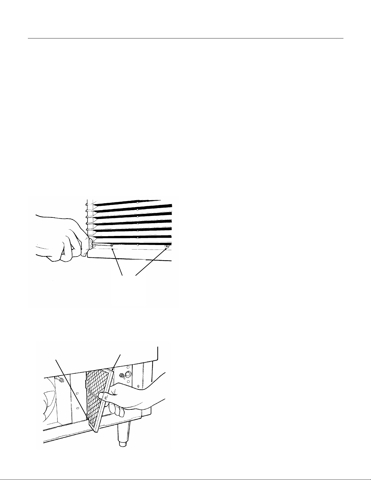
Air Filter (air cooled only):
1. Remove the grills on the front of the unit.
2. Remove two screws and the bracket holding the
filter to the condenser.
4. Wash the surface of the filter off with cold water,
or , if t orn or so dir t y it can’t be cleaned, r eplace
with a new filter.
5. Return the filter to its installed position.
6. Replace the bracket removed in step 2.
7. Replace the grills. Do not operate the unit
without the filter in place.
Note: If the unit has been operated without the
filter in place, the fins of the condenser will
become fouled with dirt, and must be cleaned.
Scotsman recommends that only the surface of
the condenser be cleaned with the bin in place. A
vacuum cleaner with a soft brush attachment will
extract most loose dust stuck to the surface of the
condenser fins. If there is any doubt about dirt
inside the fins of the condenser, the cabinet should
be removed and a qualified service agent should
clean the condenser.
Water cooled unit s:
The water cooled condenser may, over time and
under certain water conditions, become internally
restricted by minerals. These will have to be
dissolved by acid or the condenser replaced. Only
a qualified service agent should attempt this type
of service.
Grill Screws
3. Pull the filter forward and twist it slightly to pull it
though the slot in the front base of the ice machine.
Air Filter
Slot In Base
October 1998
Page 13
Page 14

SCE170
Sanitizing and Water System Cleaning
Cleaning Water Syst em:
The water system is cleaned by pumping a mixture
of water and
cleaner
nickel safe type ice machine
through the water distributor, over the
evaporator and back to the reservoir.
1. Open the door and empty the bin of ice.
2. Remove the right front grill.
3. Locate the Harvest switch; activate harvest
cycle for 2 minutes or until ice falls from the
evaporator.
4. Locate and move the ON/OFF/CLEAN switch to
CLEAN.
5. Open and close the curtain to release any
cubes.
6. Mix a solution of 1 quart of warm (95
water and 1 ounce of
nickel safe ice machine
0
F. - 1150F.)
cleaner, such as Scotsman Nickel-Safe.*
Ice Machine Cleaner
contains acids. These
compounds may cause
burns.
If swallowed, DO NOT
induce vomiting. Give
large amounts of water or
milk. Call Physician
immediately. In case of
external contact, flush
with water.
KEEP OUT OF THE
REACH OF CHILDREN.
7. Locate the purge switch, push it to ON and hold
it ON until the reservoir is nearly empty.
8. Immediately pour the cleaning solution into the
reservoir and allow it to circulate through the water
system for 20 minutes.
Pouring In
Cleaning Solution
Reservoir
Curtain
9. Either A) Move the purge switch ON and hold it
until the reservoir is nearly empty;
or
B) Remove the drain plug, drain the reservoir &
replace the plug.
10. Open the curtain and check the condition of
the evaporator surface, if it appears clean procede
to the next step. If mineral scale is still present,
repeat steps 6-9 one more time.
Note: The ice making portion of the water system
should be sanitized after cleaning by repeating
steps 7-9, except substitute an approved sanitizing
solution (such as a mixture of 1 oz. of household
bleach to 2 gallons of warm {95
0
F. - 1150F.} water)
for the cleaning solution.
Harvest
Switch
Purge
Switch
On/Off/Clean
Switch
Note: Sanitizer need only circulate water system
for 2 minutes, or the time on the sanitizer
instructions. Retain the balance of the sanitizer
solution for sanitizing the bin interior.
11. After the reservoir refills, move the purge
switch up until the reservoir is nearly empty. Allow
the reservoir to refill. Repeat 4 times.
12. Move the ON/OFF/CLEAN switch to ON and
replace the grill.
13. Discard the next batch of cubes.
14. The unit is now ready for automatic operation
or sanitizing of the ice storage bin.
* Scotsman Nickel Safe Cleaner is available by
ordering part number 19-0636-06 (8 oz bottl e) .
October 1998
Page 14
Page 15

Sanitizing and Cleaning
SCE170
Water Distributor:
Note: The water distributor may need to be
cleaned separately.
1. Remove right front grill.
2. Switch master switch to OFF.
3. Open bin door.
4. Locate hood fasteners at the left and right inside
walls of the hood, and remove the hood.
5. Remove the curtain.
6. Locate wing-nuts at the top of the water
distributor and remove them.
7. Remove inlet hose from water distributor.
8. Pull water distributor forward and out of t he ice
machine.
The distributor may be pulled apart and any
mineral accumulation washed out. Sanitize the
water distributor and curtain after cleaning.
Reverse the above steps to reassemble.
The storage bin must be cleaned regularly to
maintain a sanitary environment. Once a week
cleaning of the door and door frame with soap and
water, a hot water rinse and an air dry is a basic
procedure. Scale that may form on the plastic liner
can be removed by scrubbing the surface with a
mixture of Scotsman Ice Machine Cleaner and hot
water. Remove any scale prior to cleaning.
To Remove Scale:
1. Mix a cleaning solution of 4 ounces of Ice
Machine Cleaner to 4 pints of hot (95
water.
2. Using rubber gloves, dip a nylon scouring pad
into the cleaning solution and scrub the scale off
the liner.
3. After the scale has been removed, rinse all
surfaces inside the bin with clean, potable water.
0
F.-1100F.)
To Sanitize The Bin Interior:
The hood must be removed from the storage bin
so that the joint between the two can be cleaned
and sanitized.
To remove the hood:
1. Open the storage bin door and locate the knobs
at the right and left inside wall.
2. Unscrew and remove the two knobs.
3. Pull the hood assembly and door straight out
from the ice machine. Note: the door may be then
be removed from the back of the hood.
Use an approved sanitizer and follow the
directions and warnings of that sanitizer or use the
following instructions for use of household bleach,
if it meets local codes:
1. Mix sanitizing solution of 1 ounce of household
bleach to 2 gallons of water.
2. Using clean rubber gloves and a clean cloth,
wipe all interior surfaces of ice storage bin, hood
and door with sanitizing solution. Be sure and wipe
the joint between the hood and bin with the
sanitizing solution. Use a clean brush or spray
bottle to thoroughly swab/spray all interior surfaces
with the sanitizing solution.
3. Reassemble and allow to air dry.
Stainless Steel Components Inside Bin
The stainless steel parts in the bin also require
periodic cleaning. Chemicals in the water supply,
such as chlorine, cause brown stains to appear on
the surface of the stainless steel parts.
1. General Cleaning - staining is usually removed
by washing the parts with ordinary cleaning
powder such as Bon-Ami or Copper-Glo and
water . Aft er cleaning, ri nse with clear wat er.
2. Water treat ment . The chlori ne enter s t he
machine from the municipal water supply. It can be
removed from the water supply by using a
charcoal or activated carbon water filter to tr eat t he
water to the ice machine. If staining is severe,
filters of this type are recommended.
Exterior Cabinet Cleaning:
The exterior cabinet may be cleaned by scrubbing
with soap and water. Do not use cleaners
containing petroleum products.
A nylon t y pe br ush may be used t o scr ub st ubbor n
deposits.
October 1998
Page 15
Page 16
SCE170
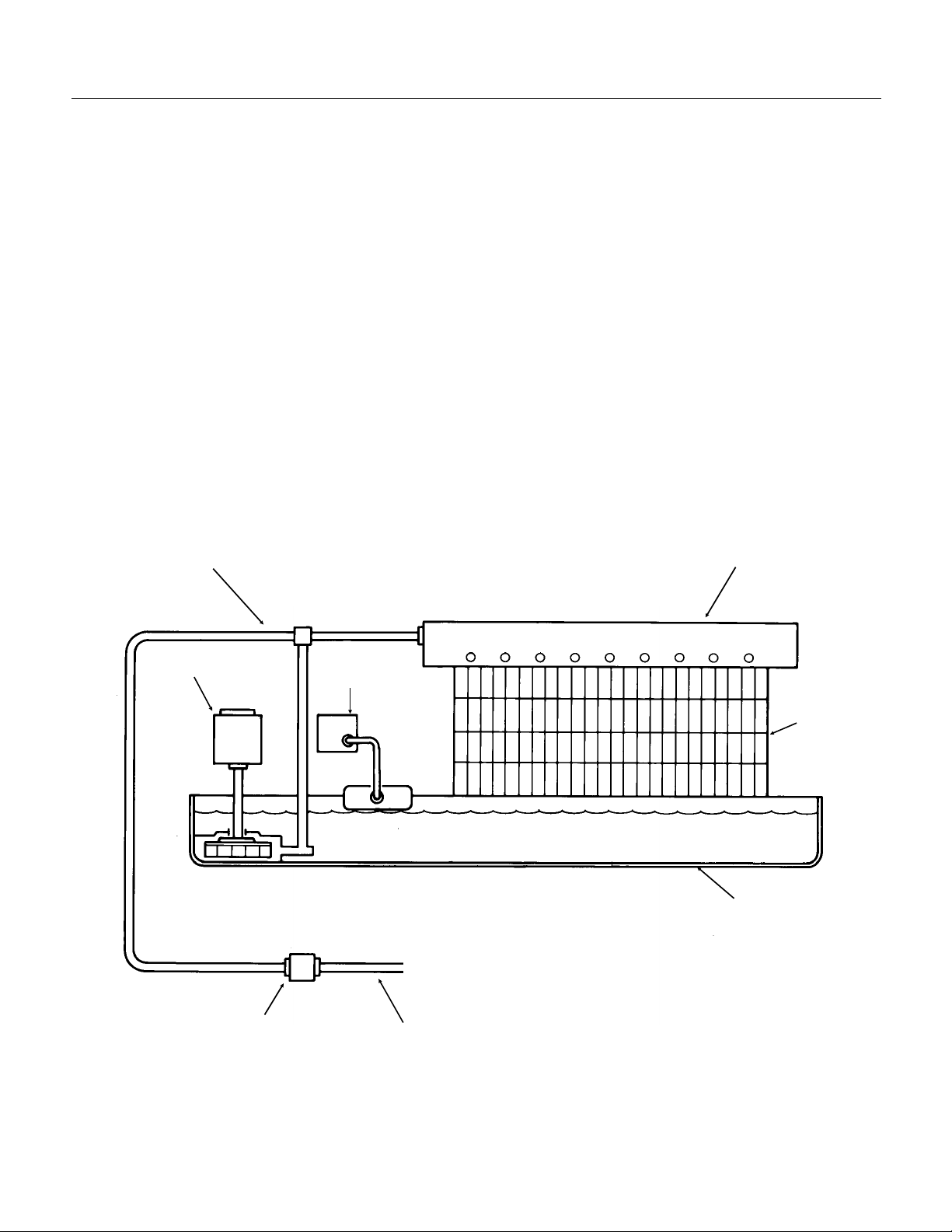
Water Schematic:
Water flows into the ice machine from its inlet
connection at the back of the cabinet, through the
float valve and into the reservoir. The water in the
reservoir is pumped up and through the water
distributor tube at the top of t he evaporator. From
there, the water flows over freezing surf ace of t he
evaporator and back into the reservoir. Melted ice
and water spills into the bin flow through a drain in
the base of the bin to the exterior drain connection
at the back of the cabinet.
During the Harvest Cycle, the Purge valve opens,
allowing the water pump to discharge water from
the reservoir to the drain. At the same t ime water
re-enters the reservoir . Very little water will flow
across the evaporator during this time.
Pump Discharge Tube
Water Pump
Water Distributor
Water Inlet
Valve
Evaporator
Reservoir
WATER SCHEMATIC
Purge Valve
To Drain
October 1998
Page 16
Page 17
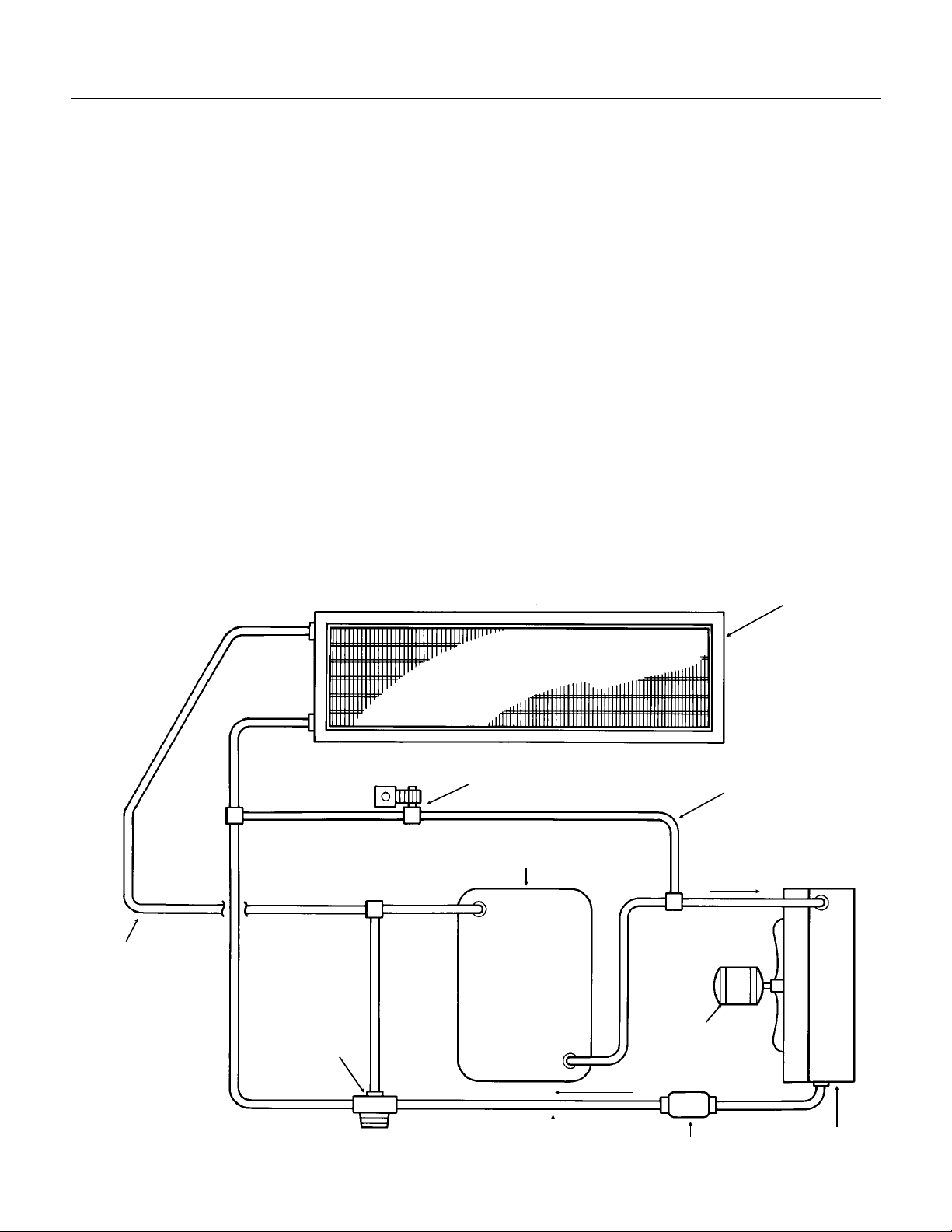
Refrigeration Schematic:
SCE170
Freeze Cycle:
From the compressor, hot discharge gas is
pumped to the condenser, either air or water
cooled.
At the condenser, heat from the refrigerant flows
into the cooling medium, either air or water, and
the refrigerant condenses into a liquid. From the
condenser the liquid refrigerant flows through the
liquid line to the metering device - a thermostatic
expansion valve.
At the externally equalized thermostatic expansion
valve, the liquid refrigerant passes from a high
pressure zone to one of relatively low pressure,
and in the low pressure zone it evaporates. The
low pressure zone where the refrigerant
evaporates is the evaporator. When the refrigerant
evaporates, it absorbs heat from the metal parts of
the evaporator and the water flowing over it.
From the evaporator, the refrigerant flows back to
the compressor through the suction line.
Harvest Cycle:
During the harvest cycle, the refrigerant flows from
the condenser , through the discharge line to a
branch in the line containing the Hot Gas Valve.
This valve is Open during the harvest cycle,
allowing the hot discharge gas to bypass the
condenser and enter the evaporator at its inlet.
The hot discharge gases warm up the evaporator
enough to allow the surface of the ice frozen to the
evaporator to melt. The remaining ice will then fall
off into the bin.
Suction Line
Thermostatic
Expansion
Valve
REFRIGERATION SCHEMATIC:
Hot Gas Valve
Compressor
Evaporator
Hot Gas Line
Fan Motor
October 1998
Page 17
Liquid Line
Dryer
Condenser
Page 18

SCE170
Technical Characteristics
Typical Cycle Time
•15 - 20 minutes (time depends upon how clean unit is, plus the air and water temperatures).
Typical Harvest Ice Weight
•1.6 to 1.8 lb. ice harvested per cycle.
Typical Low Side Pressure
•25 PSIG just before harvest
Typical Freeze Cycle Discharge Pressure
•Air cooled: 300 PSIG declining to 210 PSIG
•Water cooled: 245 PSIG
Refrigerant Type / Charge
•Air Cooled: R-404A / 17 ounces A series, 16 ounces B and Cseries
•Water Cooled: R-404A / 9 ounces A series, 11 ounces B series and 10 ounces C series
Harvest Time:
•Varies with ambient, usually about 1.5 - 2 minutes. Unit is in harvest until the curtain opens. The
unit may remain in harvest a maximum of 7 minutes, after which the machine returns to the freeze
cycle.
Typical Low Side Pressure, in harvest
•85 - 100 PSIG
Typical Discharge Pressure in harvest
•195 - 210 PSIG
Hi Pressure Cut Out
•Cuts Out at (450 PSIG air cooled, 350 PSIG water cooled); Cuts In at 350 PSIG (air cooled)
Typical Compressor Amp Draw
•Freeze: 6-7
•Harvest: 7-8
Superheat
o
•4-6
Finish Freeze Time
F. 10 minutes into freeze cycle. TXV is not adjustable.
•4 minutes after cube size thermostat closes (indicator light on control board is ON in Timed Freeze)
Air cooled fan motor
•16 watt rating; 1500 RPM; CW. Stops during harvest.
Compressor
•Copeland hermetic, capacitor start, induction run.
Water Pump Motor
•4 pole, unit bearing type.
Cube Size Control
•Adjustable Cut In temperature as needed to obtain correct ice bridge thickness, about 8
•Cut In at about 31 PSIG (with normal heat load)
June 2002
Page 18
o
F. - 10oF.
Page 19

SCE170
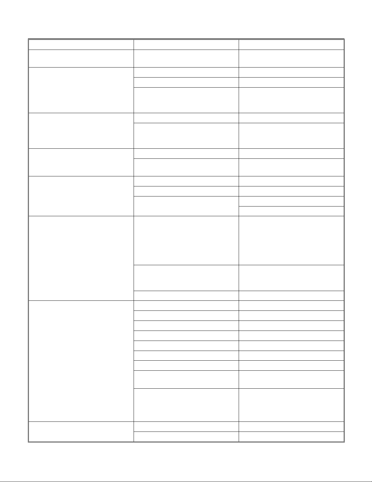
Service Diagnosis
Proper service diagnosis begins with observation, comparing the complaint to the operation of the unit. Ice
machine service diagnosis should proceed from water , to electrical and then to refrigeration.
SYMPTOM POSSIBLE CAUSE PROBABLE FIX
No ice is made No water due to water turned off. Reconnect water supply.
No water due to float valve
plugged up.
No water due to float stuck in
closed position.
No water due to purge valve
leaking water down drain.
Water in reservoir, no flow over
evaporator due to water leak at
discharge hose.
Water in reservoir, no flow over
evaporator due to pump not
operating.
Water in reservoir, no flow over
evaporator due to water
distributor plugged up.
Unit in CLEAN or Harvest cycle Switch ON/OFF/CLEAN switch to
No ice is made, nothing operates. No power Reconnect power.
ON/OFF/CLEAN switch in OFF
position
Curtain in open position Check for obstruction keeping the
High pressure cut out open, reset
and check:
Control board open Replace control board.
Unit does not shut off. Curtain sensor does not work. Check curtain sensor and control
Clean out float.
Replace float.
Replace purge valve.
Repair leak.
Replace pump.
Clean water system.
OFF and then ON.
Switch ON/OFF/CLEAN switch to
ON.
curtain open. Check that curtain
is properly mounted. Check
curtain sensor & indicator light.
Air cooled: check fan motor for
stalling, condenser/filter for dirt,
loose fan blade.
Check water cooled unit for
proper water supply
If overcharged or there are non
condensables in refrigeration
system, replace refrigerant with
correct charge.
Replace H.P. cut out if it opens at
too low a pressure.
Unit may have stuck in harvest
cycle in a very warm ambient,
check operating conditions.
system.
October 1998
Page 19
Page 20
SCE170
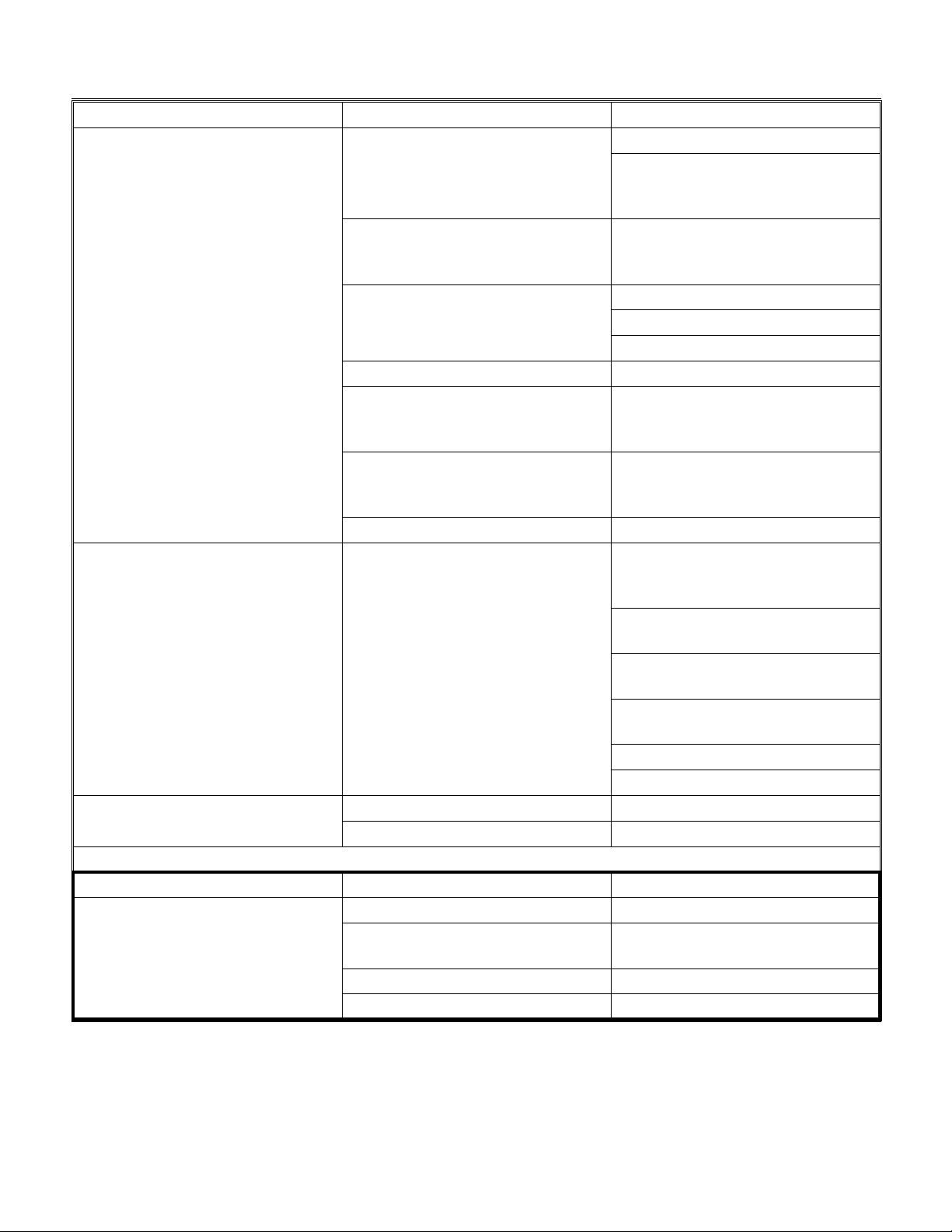
Service Diagnosis
SYMPTOM POSSIBLE CAUSE PROBABLE FIX
Unit shuts off before bin is full. Ice hangs up between curtain and
reservoir.
Makes ice, but cubes are
mal-formed.
Cubes/bridge too thick. Cube size control set too cold. Adjust cube size control.
Cubes too small, unit may stay in
harvest because ice will not push
curtain open.
Machine goes into harvest, but
ice on evaporator will not defrost freezes up.
Unit freezes, but will not try to
harvest.
Low capacity/long freeze cycle. Extreme hot location Relocate the unit.
Long harvest cycle Cube size set too large Adjust cube size
Water distributor is dirty. Clean water system.
Cube size set wrong. Adjust cube size control.
Refrigerant leak. Cubes will be
smaller or missing beginning at
the top half of the evaporator.
Refrigerant leak, causing suction
line temperature to be warm,
keeping unit in the freeze cycle.
Cube size control set too warm. Adjust cube size control.
Short freeze cycle caused by
slush.
Cube size set too small. Adjust cube size control.
Cube size set too large. Adjust cube size control.
Hot gas valve will not open. Coil of valve open, replace.
Cube size control will not close; to
check: Unplug water pump,
switch unit Off and then ON, in
about 2 minutes the Timed
Freeze Light on control board
should be ON
Timed freeze light glows, but after
4 minutes unit does not power hot
gas nor purge valves.
Very low on refrigerant Check pressures
Air cooled condenser or filter dirty. Clean condenser/filter.
Cubes too big. Adjust cube size control.
Water leak from reservoir. Repair leak.
Float valve does not shut off. Replace float.
Water temperature very high Advise user
Purge valve leaks by slowly. Replace purge valve.
Overcharged with refrigerant. Evacuate and weigh in nameplate
Hot gas valve leaks thru Check hot gas valve. There
Sticking in harvest Check cube size or for slush
Check action of curtain, check
cube size.
Locate leak, repair, replace dryer,
evacuate and weigh in nameplate
charge
Locate leak, repair, replace dryer,
evacuate and weigh in nameplate
charge
Some slush is normal. Check
purge valve for leak-thru.
Valve will not open, replace.
If timed freeze light does not go
ON, replace cube size control.
Replace control board
charge
should be frost on line between
evaporator and valve during the
freeze cycle.
October 1998
Page 20
Page 21
SCE170
Service Diagnosis
SYMPTOM POSSIBLE CAUSE PROBABLE FIX
Machine operates, no ice is
formed.
Compressor cycles on and off. Compressor overheats. Low on refrigerant. Repair leak,
Frost on compressor Some frost will not hurt. Do nothing.
Unit stuck in harvest cycle. Check for curtain stuck closed.
Cubes too small, adjust bridge
thickness, see Cube Size/Bridge
thickness section
Refrigerant leak Locate leak, repair, replace dryer,
evacuate and weigh in nameplate
charge
Compressor will not operate Check compressor contactor coil.
Check compressor.
Check compressor start circuit
Hot gas valve stuck open. Replace hot gas valve.
Refrigerant leak. Locate leak, repair, replace dryer,
evacuate and weigh in nameplate
charge.
Hot gas valve and purge valve
stay on after curtains close and
both curtain indicator lights are on.
Purge valve leaks thru. Clean or replace purge valve
TXV meters too much refrigerant. Replace TXV.
Replace control board.
evacuate and weigh in nameplate
charge
Air cooled - fan not blowing,
repair fan.
TXV not letting enough refrigerant
into evaporators, replace TXV.
Mechanical fault with compressor,
replace compressor.
Check start capacitor
Check start relay
To check bin control system:
When curtain is closed, BOTH
curtain indicator lights on the
control board in the control box
should be ON, if not:
Curtain not closed properly Check action of curtains
Sensor not in correct position Place sensor assembly in correct
position
Curtain missing Replace curtain
Curtain sensor has failed. Replace sensor assembly.
October 1998
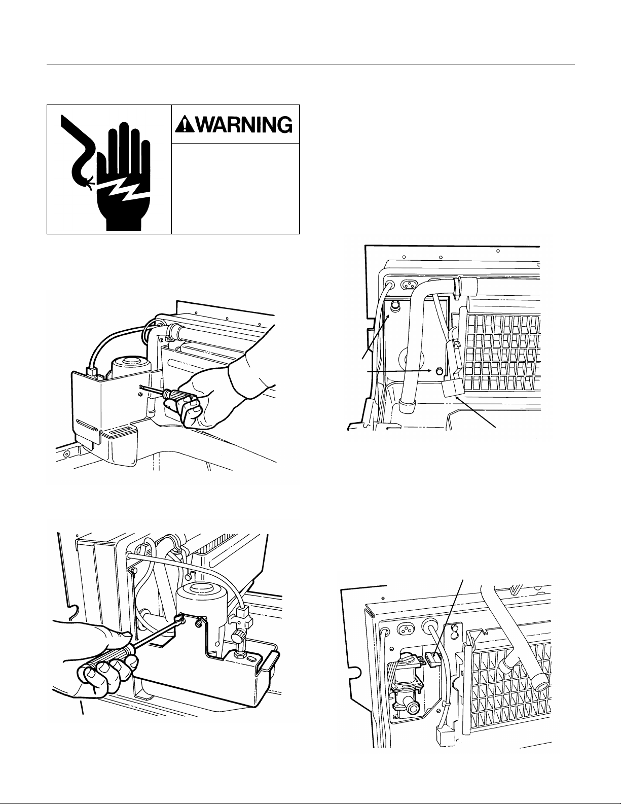
Page 21
Page 22

SCE170
Removal and Replacement: Cube Size Control
Control Box Service
The control box may be lifted up from its normal
position to improve service access.
To Move Control Box
1. Disconnect electrical power.
Electrical shock hazard.
Electrical shock can
cause personal injury.
Disconnect power before
beginning to service
components.
2. Go thru the steps to remove the hood, door and
bin.
3. Locate and remove the 3/8" hex head screw
holding the control box to the base, just below the
purge switch.
4. Pull the control box forward about an inch.
5. The control box may now be moved up the
height of the control box, be careful not to kink any
capillary tubes.
6. After service, replace the control box in its
normal position.
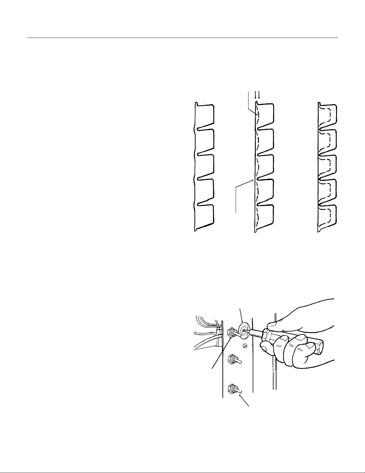
Cube Size Control (bridge thickness):
Before replacing the cube size control, it should be
positively determined that it is at fault.
Check the operation of the cube size control by
unplugging the water pump, removing the right
front grill and control box cover , and watching the
Timed Freeze Light. With no ice on t he evapor at or,
switch the ice machine to ON. The temperature of
the suction line where the cube size control bulb is
located should be about 8-10
into the freeze cycle (with the water pump
unplugged). Or the low side pressure should be
about 31-32 PSIG. The cube size control should
then close its contacts and cause the T i med
Freeze Light on the control board to be ON. If it
cannot be adjusted to close at that point, or if it
does not open when warm, replace it.
1. Disconnect electrical power.
o
F. about 2 minutes
Electrical shock hazard.
Electrical shock can
cause personal injury.
Disconnect power before
beginning to service
components.
2. Remove the hood, door and ice storage bin.
3. Remove the control box cover.
4. Locate the cube size control.
5. Remove the two screws holding the control to
the control box, and lift the control out.
6. Pull the two wires off the posts of the cube size
control.
7. Follow the capillary tube of the cube size control
and remove it from the grommet in the back of the
control box.
8. Locate bulb on suction line and remove
insulation covering bulb.
9. The end of the cube size control is inserted in a
socket attached to the suction line. Pull it out of the
socket.
10. Replace the cube size control with the proper
part number, following the above steps from 9-1.
Be sure to re-insulate the cube size control bulb.
October 1998
Page 22
Page 23

Removal and Replacement: Water Pump
SCE170
Water Pump
The pump provides the force to move the water
from the reservoir to the freezing surface. The
pump does not need oil, but if it becomes noisy,
overheats, or will not pump it should be replaced.
Be certain to confirm electrical faults with a
voltmeter or ohmmeter before replacing the pump.
The pump should operate with the compressor.
1. Unplug or disconnect the electrical power.
Electrical shock hazard.
Electrical shock can
cause personal injury.
Disconnect power before
beginning to service
components.
2. Open the bin door and unscrew the knobs
holding the hood to the bin.
5. Unplug the pump from its connection at the
back of the stainless steel wall.
6. Loosen the two fasteners holding the pump to
the bracket.
Note: The two pump fasteners are hex head
screws. When the unit is built in, they can be
loosened using a
1
⁄
" socket.
4
3. Pull the hood off the bin. Note: the bin door will
come out the back of the hood when the hood is
removed from the bin.
4. Remove screw and pump shield.
Pump
Shield
7. Pull discharge hose from pump discharge port.
8. Remove pump from ice machine.
9. Reverse above steps to replace.
October 1998
Page 23
Page 24

SCE170
Removal and Replacement: Float Valve
Float Valve
The float valve allows water to enter the reservoir
but not overfill it. If the float sinks, or the valve will
not seat, the float valve should be replaced. The
float may plug-up from minerals in the water, and
may be cleaned rather than replaced.
1. Shut off the water supply.
2. Open the bin door.
3. Remove the pump shield.
4. Unscrew the compression fitting at the top of t he
float, and pull the water inlet tube out of the valve.
5. Loosen the nut securing the float to the bracket.
6. Pull the float to the right and out to clean or
replace.
7. Reverse the above steps to reassemble.
Note: This illustration shows
the pump removed.
It is NOT necessary to remove
the pump to remove the float.
Float Valve
October 1998
Page 24
Page 25

Removal and Replacement: Curtain & Bin Control
Bin Control Sensor
The bin control sensor should only be changed if it
has been determined that it has failed. An easy
check is to remove the right grill and the control
box cover . Then, wit h no ice near t he cur t ains and
the machine plugged in (& switched on), move the
curtain in and out. The light on the board in the
control box should go on and off with the motion of
the curtain. If not, replace the bin control sensor.
1. Disconnect electrical power.
Removal/Replacement of Bin Control Sensor
SCE170
2. Remove the hood, door and ice storage bin.
3. Locate bin control sensor on the left end of the
evaporator.
4. Move the bottom of plastic sensor housing left
until the pin is clear of the hole in the evaporator
bracket.
5. Pull the sensor housing up and out of the slot in
the evaporator bracket.
6. Trace wires to plug connecti on near cont r ol box,
unplug and remove assembly from unit.
7. Reverse to reassemble. Note: Bin control
sensor must be full seated in the slot and the pin
snapped into the matching hole in the bracket.
Curtain
The Curtain has a magnet embeded in the left
end. The location of this magnet is used by the bin
control sensor to determine harvest and bin full. To
replace the curtain:
1. Open the bin door.
2. Pivot curtain forward, push each
end of curtain up and pull forward to
remove plastic pivot pins from the
metal evaporator bracket’s slot.
Thin Groove
(Front Edge View)
Evaporator
Bracket
Bin
Control
Sensor
Slot
Hole
Pin
Curtain
Removal/Replacement of Curtain
Metal
Evaporator
Bracket
3. Reverse to reassemble.
Note: Pivot pins must be
installed with metal edge in
the thin groove of the pin.
When installed, Pivot pins
must be at the bottom of the
Curtain Hanger Slot.
Pivot Pin
Metal
Evaporator
Bracket
Curtain
Hanger
Slot
Curtain
Pivot Pin
October 1998
Page 25
Page 26
SCE170
Removal and Replacement: Purge Valve
Removal:
1. Unplug unit.
Electrical shock hazard.
Electrical shock can
cause personal injury.
Disconnect power before
beginning to service
components.
2. Open bin door, remove hood fasteners and pull
hood from ice machine.
3. Remove one screw and pump shield.
6. Pull pump up and out of the machine. Retain for
re-installation.
7. Remove curtain, set aside for re-installation.
8. Shut water off.
9. Loosen float valve retaining nut, slide float valve
to the right and allow to hang by the incoming
water line.
10. Remove plug from under reservoir and drain
the reservoir.
11. Unclip curtain sensor.
Pump
Bracket
Bolts
4. Loosen 2 screws (1/4" hex head) holding pump
to bracket.
Curtain Sensor
12. Remove reservoir support fastener from left
end of reservoir.
13. Remove lower pump bracket bolt, and
upper pump bracket bolt.
14. Remove pump bracket and set aside; lower
reservoir into bin.
15. Locate electrical power plug to purge valve
coil, remove plug.
Plug
loosen
5. Disconnect discharge hose from pump, water
distributor and valve.
October 1998
Page 26
Page 27
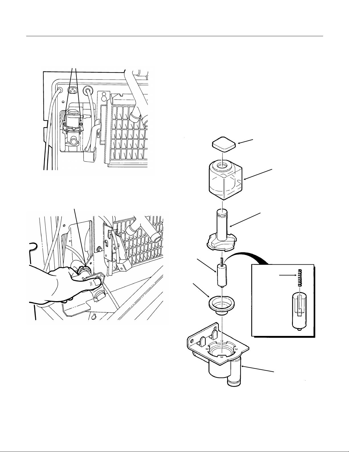
Removal and Replacement: Purge Valve
SCE170
16. Unscrew the two screws holding the purge
valve to the ice machine.
Mounting Screws
17. Pull the purge valve forward until the discharge
hose clamp is accessible.
Hose Clamp
Service:
19. Remove coil:
Flip plastic retainer up and slide off valve.
Pull coil up and off valve.
20. Open valve:
Rotate stem CCW as far as it goes.
Lift stem up and off valve.
Pull up on plunger - do not loose spring.
21. Examine seat & plunger for dirt/damage. Clean
and reassemble. If damaged, replace valve.
Plastic Retainer
Coil
Stem
18. Loosen hose clamp and pull purge valve from
ice machine.
Plunger
Spring
Seat
Valve Body
Service of Purge Valve
22. Reverse above steps with original parts or new
valve to reassemble.
October 1998
Page 27
Page 28

SCE170
Water Distributor
The water distributor tube will typically not require
any service beyond removal for cleaning. If
needed, remove the water distributor by:
1. Remove the hood.
2. Remove lower right front grill.
3. Switch master switch to OFF.
4. Loosen hose clamp at water distributor inlet (on
left).
5. Remove the two wing nuts holding the
distributor to the evaporator.
6. Lift water distributor off the studs.
7. Pull the inner distributor tube out of the out er
distributor tube and clean out all holes.
To reassemble.
8. Align the tube so that the inner distributor t ube’s
holes are opposite the outer distributor tube’s
holes.
9. Place the end caps onto the water distributors.
10. Place the distributor tube onto the mounting
studs:
Inner Distributor
Tube Water Outlet
Outer Distributor
Tube
Side View of the Water
Distributor
Wing Nut
Evaporator Stud
Water Oulet
Evaporator
Bracket
NOTE: The Outlet Holes Face Down, Towards
The Evaporator.
11. Replace the wing nuts, hose and hose clamp.
12. Switch the machine back on and check the
water flow.
13. Replace the hood.
Inner Water
Distributor Tube
Hose Clamp
Water Inlet
Hose
Wing
Nut
End Cap
Outer Distributor
Tube
Evaporator Bracket
October 1998
Page 28
Water Distributor Assembly
Page 29

Refrigeration System Service: HP62 (R-404A)
Pressure-Temperature Chart for HP62
This ice machine uses R-404A r ef r i ger ant and
polyolester oil. Do NOT use mineral oil in this
refrigeration system.
R-404A is a "Near Azeotrope" so liquid
•
charging is required:
Weigh in as liquid as much of the charge as
¤
possible into the discharge line.
Install a sight glass between the manifold and
¤
the suction side hose and carefully meter
liquid into the suction side, using the manifold
valve to "flash off" the liquid before it enters
the ice machine. Do this until the proper
amount of refrigerant has been weighed into
the system.
When the system is serviced, a special liquid
•
line drier is required. It is included with
replacement compressors.
HP62 is not compatable with mineral oil, so
•
these ice machines use Polyolester oil.
Polyolester oil absorbs water very easily. When
one of these refrigeration systems is opened for
service, it must be re-sealed as soon as
possible (15 minutes maximum).
Special leak detection equipment is required to
•
locate small refrigerant leaks. Usually a leak
detector capable of dectecting a Halongenated
refrigerant or HFC-134A will work. Check with
the leak detector manufacturer if in doubt.
VAPOR VAPOR
TEMP. PRESSURE TEMP. PRESSURE
(DEG F) (PSIG) (DEG F) (PSIG)
-20 . . . . . . 17 70 . . . . . . . 146
-18 . . . . . . 18 72 . . . . . . . 150
-16 . . . . . . 20 74 . . . . . . . 155
-14 . . . . . . 21 76 . . . . . . . 161
-12 . . . . . . 23 78 . . . . . . . 166
-10 . . . . . . 24 80 . . . . . . . 171
-8 . . . . . . . 26 82 . . . . . . . 177
-6 . . . . . . . 28 84 . . . . . . . 182
-4 . . . . . . . 29 86 . . . . . . . 188
-2 . . . . . . . 31 88 . . . . . . . 194
0 . . . . . . . 33 90 . . . . . . . 200
2 . . . . . . . 35 92 . . . . . . . 206
4 . . . . . . . 37 94 . . . . . . . 212
6 . . . . . . . 39 96 . . . . . . . 219
8 . . . . . . . 41 98 . . . . . . . 225
10 . . . . . . . 43 100 . . . . . . 232
12 . . . . . . . 46 102 . . . . . . 239
14 . . . . . . . 48 104 . . . . . . 246
16 . . . . . . . 50 106 . . . . . . 253
18 . . . . . . . 53 108 . . . . . . 260
20 . . . . . . . 55 110 . . . . . . 268
22 . . . . . . . 58 112 . . . . . . 275
24 . . . . . . . 60 114 . . . . . . 283
26 . . . . . . . 63 116 . . . . . . 291
28 . . . . . . . 66 118 . . . . . . 299
30 . . . . . . . 69 120 . . . . . . 307
32 . . . . . . . 72 122 . . . . . . 316
34 . . . . . . . 75 124 . . . . . . 324
36 . . . . . . . 78 126 . . . . . . 333
38 . . . . . . . 81 128 . . . . . . 342
40 . . . . . . . 85 130 . . . . . . 351
42 . . . . . . . 88 132 . . . . . . 360
44 . . . . . . . 91 134 . . . . . . 370
46 . . . . . . . 95 136 . . . . . . 379
48 . . . . . . . 99 138 . . . . . . 389
50 . . . . . . . 102 140 . . . . . . 399
52 . . . . . . . 106 142 . . . . . . 409
54 . . . . . . . 110 144 . . . . . . 420
56 . . . . . . . 114 146 . . . . . . 430
58 . . . . . . . 118 148 . . . . . . 441
60 . . . . . . . 123 150 . . . . . . 452
62 . . . . . . . 127 152 . . . . . . 464
64 . . . . . . . 132 154 . . . . . . 475
66 . . . . . . . 136 156 . . . . . . 487
68 . . . . . . . 141 158 . . . . . . 499
SCE170
October 1998
Page 29
Page 30
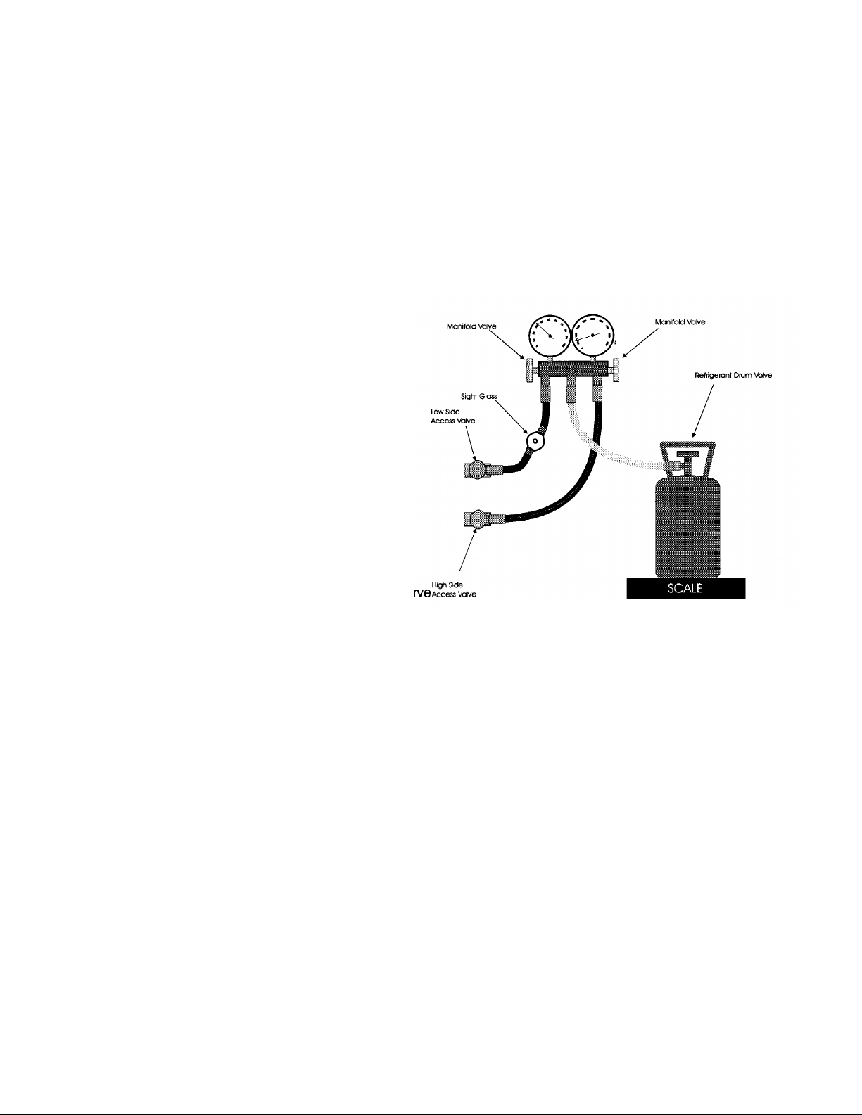
SCE170
Liquid Charging
Instructions for R-404A
In preparation for charging, the low side hose should have a sight glass, and/or a restrictor device (such as
a "Charge Faster") installed in it for metering liquid into the low side of the system.
1. After a thorough evacuation to at least 200 microns, shut off the manifold valves and switch off the
vacuum pump.
2. Place a drum of R-404A onto an electronic
scale.
3. Attach the charging hose to the dr um.
4. Open the valve on the drum and purge the
charging hose.
5. Zero out the scale.
6. Shut the low side access valve at the ice
machine.
7. Open the discharge manifold valve full open.
8. Watch the scale, when t he cor r ect char ge is
shown, shut the manifold valve.
Note: If all of the charge will not "go in" the
discharge side:
A. Shut the discharge access valve at the ice
machine.
B. Switch the machine on.
C. Open the low side access valve at the ice
machine.
D. Open the low side manifold valve and observe
the sight glass to be certain that only gas is
flowing into the system.
E. When the proper charge is indicated on the
scale, shut off the manifold valve(s).
9. Shut off the valve on the ref r i ger ant drum.
10. Re-open the manifold valves until all liquid has flowed out of the hoses.
11. Shut the low side access valve on the ice machine.
12. Remove hoses from ice machine and replace all caps.
Hose Connection Schematic for Liquid Charging
October 1998
Page 30
Page 31
Refrigeration Service
SCE170
General Information:
Work on the refrigeration system should only be
done when it is certain that the system needs
repair.
Refrain from checking refrigeration
•
pressures without reason.
of the water system, observation of the ice
formation, amp draw, voltage, and other
techniques will lead to proper diagnosis.
Scotsman also recommends that, at the time of
initial start up, gauges not be used.
If gauges must be used, don’t always check the
•
high side pressure. If the condenser is clean
and seems to be operating correctly, it most
likely is. The low side pressure is more
important on an ice machine than the high side.
If gauges must be used, use very short hoses
•
to minimize refrigerant discharged into the air.
Refrigerant should not be added except as a
•
way to determine the proper operation of the
product. If the system was low on refrigerant,
there is a leak, and it must be found and
repaired.
This system has a critical charge, it must be
•
recharged with the correct amount of refriger ant
as listed on the nameplate of the ice machine,
or performance will suffer.
Anytime the refrigeration system has been
•
opened, the dryer should be replaced.
Visual inspection
Note:
Only a HFC type dryer should be used.
When brazing the tubing connections to
•
components such as the TXV, the component
must be protected by heat sink material.
Recover , reclaim or recycle refrigerant
method chosen is up to the service company. Any
refrigerant placed into a Scotsman ice machine
must meet ARI spec 700-88. Reclaim programs
are available through most refrigerant wholesalers.
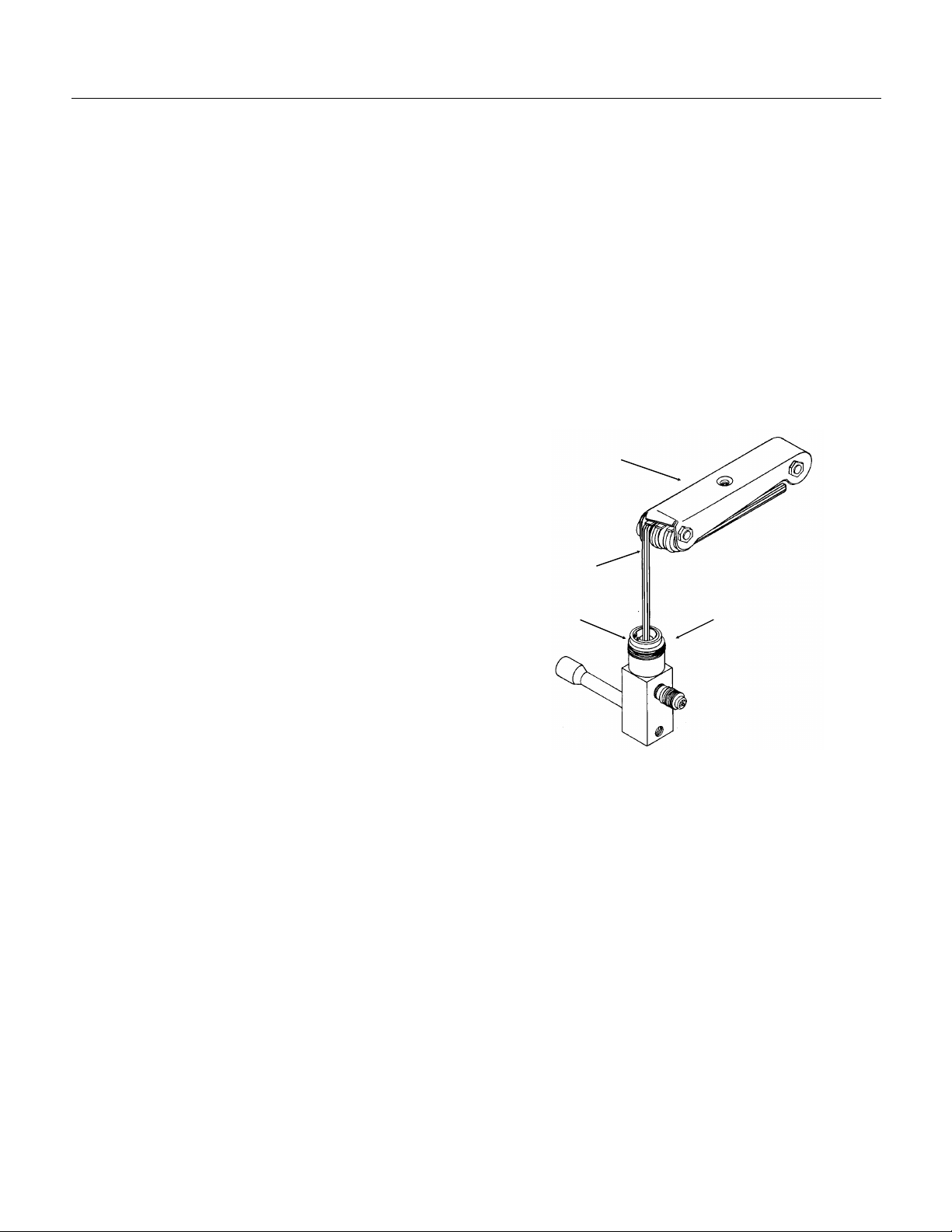
Access V al ves:
Remove the cap from the stem, use a 3/16" allen
wrench to check that the valve is CLOSED. The
remove the core cap.
Close the valve and replace the caps when the
job is finished. The valve must be closed and
the caps must be on or the valve will leak.
Wrench
Torque Stem to
6-8 ft. lb.
Torque Stem Cap to
8-12 ft. lb.
To use the access valves:
Allen
Torque
Core Cap to
7-12 ft. lb.
Access Valves
Note: There are no valve
cores in this valve.
. The
October 1998
Page 31
Page 32
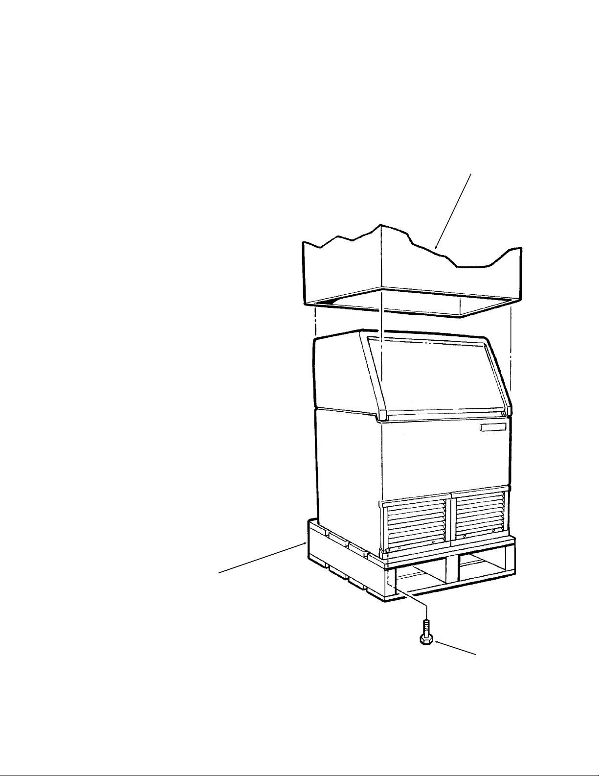
UNPACKING
1. Inspect the cabinet for shipping damage. Report
any damage to the freight carrier within 15 days of
delivery. If a damage claim is to be filed, retain the
carton.
2. Locate the service manual in the ice storage bin.
Refer to it for installation instructions.
3. Remove the box containing the legs from the ice
storage bin.
4. The ice machine is fastened to the skid. The
bolts securing the ice machine to the skid screw in
from the bottom.
To remove:
Use part of the carton as a cushion and tip the
ice machine onto its back.
Remove the bolts holding the skid to the ice
machine and the skid.
Install the legs.
Return the ice machine to an upright position.
5. Remove any shipping tape on the door and
inside the ice storage bin. Remove any
packing material found in the bin.
CARTON
Note: When moving the machine, do not drag
it; dragging the machine may cause damage to
the legs or the cabinet.
SKID
17-2089-01
BOLT
 Loading...