

Page 1

RFE33
Introduction
The Scotsman RFE33 Compact Refrigerator is a
unique product, capable of being built into a
cabinet because of its front vented, forced-air
cooling system.
It’ s als o designed to be a compan ion to
Scotsman ’s DCE33 A u tomatic Ice Ma ch ine . To
prevent door interference when installed to the left
of a DCE33, the RFE33 comes from the factory
with the door hinge d on the le ft . The do or s wing
may be reverse d to suit the ins ta llat ion .
The RFE33 keeps its inte rior cool b y remo ving
heat from the freezin g compartmen t at the top of
the storage area and exhausting that heat out the
right front grill.
Table of Contents
Specifications . . . . . . . . . . . . . . . . . . . . . . . . . . . . . . . . page 2
Installation . . . . . . . . . . . . . . . . . . . . . . . . . . . . . . . . . page 3
Customizing . . . . . . . . . . . . . . . . . . . . . . . . . . . . . . . . . page 4
Reversing door swing . . . . . . . . . . . . . . . . . . . . . . . . . . . . . page 5
Installation & Operating . . . . . . . . . . . . . . . . . . . . . . . . . . . . page 6
Routine Maintenance . . . . . . . . . . . . . . . . . . . . . . . . . . . . . page 7
Problems . . . . . . . . . . . . . . . . . . . . . . . . . . . . . . . . . . page 8
Specialized Service . . . . . . . . . . . . . . . . . . . . . . . . . . . . . . page 9
This product man ua l is inten ded to be a resource
for inst alla tio n, routin e main tena nc e, an d service
diagnosis.
Although there have been several changes in
appearanc e and comp on en ts , this man u al co v e rs
all models of the RFE33.
Note the warning symbol whe re it appea rs in this
manual, it is an alert that there may be some
hazard noted in that se ctio n of the man ua l.
A parts list is located in the center of this manual,
printed on colored paper.
Scotsman reserves the right to make design changes
and/or improvements at any time. Specifications and
design are subject to change without notice.
Keep this man u al f o r fut ure reference.
This manual was printed on recycle d paper.
November 1995
Page 1
Page 2

RFE33
Specifications:
Model Finish
RFE33A-1WA White 3 + cu. feet 1" foamed in place polyurethane
Capacity Insulation Compressor Condenser Type
1
⁄16H.P.
Forced Draft
RFE33A-1WB White same same same same
RFE33A-1BB Black same same same same
RFE33A-1SB Stainless same same same same
Kits: Stainless steel door sleeve conversion kit is K-SS. Cabinet extension kits include KCE18-W (white) and
KCE18-B (black).
Note: Right and Left
Placement of Machines Will
Not Affect Performance.
Cabinet dimensions are critical
to a built in installation. The
diagrams illustrated below
RFE33
show the details of the cabinet
construction.
29 7/8"
74.0 cm
4"(10.2 cm)
to bottom of
legs
2"
5.1 cm
1/2"
1.3 cm
September 2000
Page 2
Page 3
Installation:
RFE33
After the carton has been removed, check for any
concealed damage. Check the unit interior and
exterior.After this check, the unit may be installed.
Open the door and remove all packing materials,
including warranty packet, tape, and warranty
registration. Note: Keep the filler plate for use
when reversing door swing.
Wipe the interior of the cabinet with soap and
water to remove any manufacturing or shipping
residue.
The RFE33 will work fine as a free standing
refrigerator, minimal attention to leveling, electrical
power supply and no obstruction of air flow will
provide an adequate environment.
The RFE33 is only designed to be operated
indoors. Malfunctions due to outdoor operation will
not be covered by warranty.
o
Excessive heat (over 100
performance.
When built in, some precautions must be taken:
Size: The space occupied by the refrigerator is:
1
•15
⁄4" wide (including screw heads at the
F.) will cause poor
base)
•24" deep to the front edge of the door handle
3
•33
⁄8" high (337⁄8" to the top of the door
hinge).
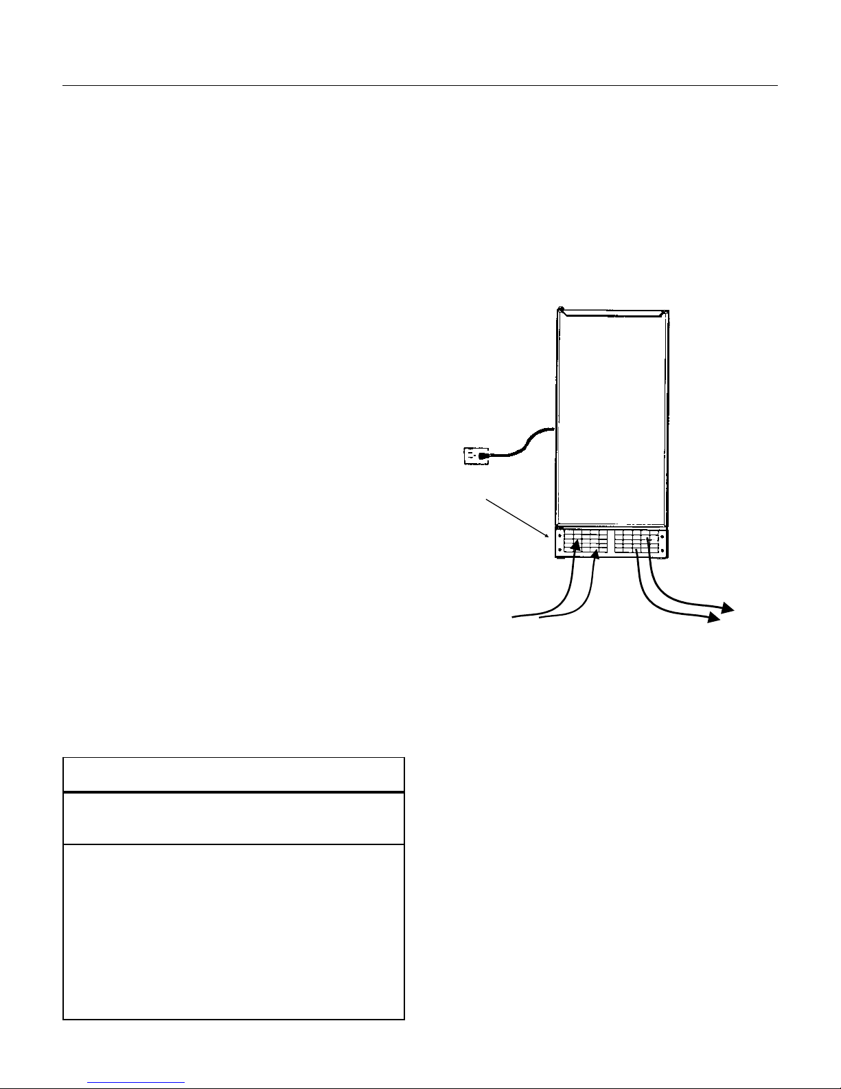
There is a kick plate at the bottom front of the
cabinet, the louvers in that kick plate allow air
to flow through the cooling mechanism, and
those louvers must not be blocked at any time.
Air Flow of RFE33
Kickplate
Air In
Air Out
Note: When installed in a corner,the door
swing may be limited due to handle contact
with the wall or cabinet face.
Danger!
Risk of Child Entrapment
Beforediscardingthe productthis unit replaces, or
when discarding this product at the end of itsuseful
life:
•Take off the door
•Leave the shelves in place so that children
may not easily climb inside.
The cabinet legs should be flush with the floor, so
that the refrigerator may be pulled out without
damage to the floor.
The electrical supply must be near enough so that
an extension cord is not used. The power
requirements are 115 volts AC, 60 cycle, single
phase (normal U.S.house current). Scotsman
recommends that the refrigerator not be
connected to a circuit with high amperage
equipment already on it. Check with a licensed
electrician for recommendations. Be sure to follow
all applicable electrical codes.
The RFE33 is UL listed, meaning it has met
certain requirements for electrical safety.Any
modification or substitution of components may
violate those requirements, and Scotsman will not
be responsible for any RFE33 so modified. Always
use Scotsman replacement parts.
June 2000
Page 3
Page 4

RFE33
Customizing Door Panel :
A custom door pan el ma y be installed in front of
the standard one. Any panel 14
high and
1
⁄4" thick or less at the edges may be
used as a decorator panel. Examples of decorator
panels include woo d to match the adja ce nt
cabinet s; meta l of dif f e ren t colors to match nearb y
appliances; or just abou t an y mat erial th at will fit .
Scotsman has a stainless steel panel available to
fit this machin e , the kit number is SS3 3. If th e
material is less than 1/4" thick, the space between
the new panel and the original ma y be filled with
cardboard.
1. Remove single screw and the left hand hinge
filler plate from the top of the door.
2. Remo v e tw o scre ws fro m the top of the door
and lift off the door handle.
3. Open the door sligh tly, about one-third
or so; then, remove the front screw holding
the hinge t o th e door.
4. Loosen the rear screw of the hinge just
enough to allow the door to sag or mo v e
forwa rd. This will allow access to the top o f
the ch annel s a t the righ t and lef t edges of
the do o r.
3
⁄4" wide, 28 15⁄16"
Custom Panel,
Parts Invo l ved in Customizing Door Panel
Thin Panel
Shown Wi th
Filler.
5. From the top of the door, insert the
decorator panel (pre-cu t) e venly into the
channels; carefully slide the panel all the
way down until the panel is fully into the
bottom chan nel.
6. Chec k th at the panel is th e in all the way
and do es not p ro t ru de p ast the top ed ge of
the do o r.
7. Push the top hinge corner of the door IN
to align screw hole in the hinge with the
screw hole in the door . Install the scre w
previo usly remov e d. T ighten the othe r
screw.
8. Repla ce the do or hand le and f iller p lat e;
secure with screws previously removed.
Hinge filler
plate
Hinge
Door with
groove
Door Handle
November 1995
Page 4
Page 5

Reversing Door Swing:
The RFE33 was ship pe d with the door hinged at
the left. The door and hinges are designed for
placing the hinges on either the right or the left
side of the cabinet. Moving the hinges to the right
allows the door to piv ot from th e right sid e .
Note: There is a part, pac k e d with the ma chin e ,
that is required f or this procedure.
1. Open the door and remove the three screws
holding the lo we r hin ge to the ca bin et .
2. With the door open enough to see both screws
at the top door hinge, remove the tw o screws . Th e
door is now free of the cab ine t.
3. Remo v e the sin gle scre w and the hinge fille r
plate from the top of the door.
4. Inst all the other f iller plat e (shippe d inside
refrig e r ator co mpartmen t ) o nt o the top corner of
the door where the hinge was.
5. Remove the three plast ic plu gs from the top
front corner where the hinge will mount.
RFE33
Door Handle
Filler Plate
Hinge
6. Remove the three plast ic plu gs from the lower
front corner where that hinge will mount.
7. Remove the three screws holding the top hinge
to the cabinet. Remove that hinge from the top
and, flipping it upside down, install it onto the
bottom of the door, on the opposite side using the
original screws.
8. Remove the hinge assembly from the bottom of
the door, and flip it up sid e down ; secure it to the
cabinet at th e opposite side top position with the
original screws.
9. Hold the door up to the cabinet. Secure the door
to the top hinge with the original screws.
10. Secure the bottom hinge to the cabinet with the
original screws.
11. Pla ce the plast ic plug s remo v e d earlier into the
empty holes.
12. Check operation of the door by opening and
closing it.
Hinge
Magnetic
Gasket
Reverse Hinges From Top to Bottom and Left to Right To
Reverse Door Swing
Door
November 1995
Page 5
Page 6

RFE33
Installation
The machine sho uld not be inst alle d in a roo m that
falls belo w 50
o
F.
Level the cabinet by turning the leveling legs at the
base of the refrigerator.
Plug the refrigerator into the electrical power
supply.
Do not slide into place until the unit has been
started.
Location of Temperature Control
Operation:
To begin operation: Open the door, locate the
temperat ure control kno b in the upper right portion
of the interior and rotate that knob clockwise until it
is about at the mid position .
The compress or and f a n mot or should both be
operating, unless the refrigerator is below 35
Check th at air is flo win g out th e righ t side of the
grill.
The metal portion of the freezing compartment will
soon fe el cold. That is th e sig na l tha t t he
refrigerat or is functio ning and the cabinet ma y no w
be placed in its installed position.
The refrigerator will require some
time to cool the air and cabinet
interior. If desired , a thermometer
may be placed in the interior and
the temperature checked. The
RFE33 should main tain
approximately 40
o
F. interior
temperature.
o
F.
Freezing
Compartment
Temperature
Control
Plastic Drip
Tray
Note: As warm products are
placed in the refrigerator, the
refrigerator will likely operate for
some time to cool t he m. When the
refrigerator is empty, it will swit ch
on and off fre quent l y becau se
there’s only air inside, and the
temperat ure of the air change s
quickly.
The tempera tu re of the
Refrigerator may be adjusted by
rotating the temperature control
knob: Turn the knob clockwise for
colder and counterclo c kwise f or
warmer .
Placing ice trays in the freezin g
compartment will reduce
refrigerating capacity.
Use: The refrigerator is
permanently lubricated , no oiling
is required. Th ere are t wo things
that do require periodic
maintenance: Th e a ir co ole d
condenser and the build up of frost
on the free zing compartment.
November 1995
Page 6
Page 7

Routine Maintenanc e & Cleaning
RFE33
General recommen dations are to keep the interio r
clean by occasionally washing it out, and if
anything shou ld sp ill inside , wiping up the spill
immediately.
The con dense r is a coil a t th e botto m of the
machine where air flows through to exhaust the
heat from the cabinet. The cond ense r should be
cleaned at least twice a yea r. The f ree zing
compartment should be defrosted whenever
frost has built up on it.
1. Condense r cle an ing: The clea ner th e co nd en se r
is the less time the refrigerator will have to operat e
to keep the interior at the correct temperature.
A. Remo v e scre ws and the kick plate at the bottom
of the cabinet.
B. Locate condenser on the left side, earlier
models had the cond en se r near th e fron t, current
models have it near the back. Use a vacuum
cleaner with an attachment that can reach the
condenser . Vac uum up all lint and dust visib le o n
the condensers fin s .
1
⁄4" of
2. Defrosting: F rost will build up on the free zing
compartment, this is normal. The frost must be
periodically allo we d to melt of f or the refrigera to r
will become ineffe ct iv e and operate f o r ve ry long
periods to try to maintain the set temperature.
A. Open the door and re mo v e all ite ms sto red in
the refrigerat or.
B. Remove any ice tray (if used ) from the freezing
compartment .
C. Check that the plast ic tray below the freezing
compartment is in place and empt y.
D. Push the button located in the center of the cold
control IN.
Defrost
Button
Condenser
Kickplate
Location of Condenser
This starts the Defrost cycle. If there is substa nt ial
frost build up the tray under the freezing
compartment will not hold all the water, and must
be emptied; check the defrost every few hours. The
RFE33 will automatically return to the refrigeration
cycle when def rost has been co mple te d. Note: This
may take up to 24 hours, so alternate storage of
perishables is required.
Caution: Do not scrape or pry ice/frost off the
freezing co mpa rtment. It is very vulnerable to
penetratio n by sh arp object s and if pie rc ed, th e
refrigerator will loose its refrigerant and will require
exte nsive service .
The most convenient time to clean the interior is
aft er defrosting the fr e ezing compartment.
November 1995
Page 7
Page 8

RFE33
Before Calling For Servi ce:
The refrigerator is a ve ry simple machine. Normal
use should not require technical se rvice. If there is
a problem with the refrig era tor, refer to this chart
before ca lling f or service.
Problem Possible Cau se Probable Solu tio n
Refrigerator will not operate Not plugged in Plug in
Breaker tr ipped/fuse blown Reset breaker, replace fuse
check operation. If breaker trips
or fuse blows again, unplug
refrigerator and reset breaker or
replace fuse. If circuit does not fail
again, call local Scotsman
Service.
Thermostat not turned cold
enough
Interior do es not get cold enough. Thermostat set too high Rotate to colder position.
Dirty condenser Clean condenser
Frosted freezin g comp art men t Defrost free zin g comp art men t
Door gasket worn Replace door gasket
Cabinet in ve ry warm sp ace Relocate or remove exce ss heat .
Gets too cold inside Thermostat set too low Rotate knob counterclockwise
Thermostat defe ctiv e Call local Scotsman service.
Will not defrost. Faulty thermostat Call for local Scotsman Service
Makes excess ive no ise Fan motor worn Call for loca l Scot sma n servic e
Rotate knob until unit starts. If unit
does not start, ca ll local Sc ot sman
service.
If none of the above will correct
the problem, ca ll local Sc ot sman
service.
November 1995
Page 8
Page 9

Specialized Service:
RFE33
The follo wing procedu res are f or the qualified
service technician only.
Thermostat
1. Unplug refrigerator from electrical power.
Electrical shock
hazard.
Disconnect electrical
power before begi nning
service.
9. Remo v e tw o scre ws atta ching the top left flange
of the thermostat housing to the inner ceiling of t he
refrigerator liner.
10. Remove two screws hol ding the lower right
flange of the thermostat housing to the right side
refrigerator line r. The capillary tube sho uld be fre e
for remo v al. Lower the housing until th e wire
connections to the thermostat can be seen.
11. Remo v e the two scre ws from th e fron t of the
thermostat housing and separate the housing from
the thermostat. Remove it from the unit.
12. Remo v e the sing le scre w from th e bottom of
the electric baffle base and cover and remove the
cover.
13. Not e the positio n of the wires, and disconnec t
the three electrical wires from th e thermostat.
14. Remove the th ermostat housing and
thermostat from the cabinet.
15. Sepa rat e the thermosta t from the elect ric
baffle, pull the capillary tube out through the hole
in the rear of the left wall of the thermost at housin g.
16. Reverse the above to replace.
Fan Motor
2. Ope n the door and pull the pla st ic tray out from
under the freezi ng compartment.
3. Lift the freezing compartmen t door and locate
the hinge wire behin d t he right side of th at do or.
Carefully push the hinge wire tow ard the center of
the door until the end of the wire has been pulled
out of the hole in the upper left wall of the
thermostat housing. Do not loose the plastic
spacer.
4. Remo v e the lef t hinge wire and spacer from the
left wall of the refrigerator liner.
5. Remove any ice trays that may be in the
freezing co mpa rtment .
6. Remove the screw and bulb holder clip to free
the end of the thermostat capillary tube from the
rear of the evap orator.
7. Remo v e the kn ob from the thermost at (pull
forwa rd).
8. Remo v e tw o scre ws (reta in space rs) and
separat e the thermosta t ho usin g fro m the freez ing
compartment (evaporator).
Note: Machine must be pulled ou t from the
installed position , an d the bac k pane l removed to
gain access to the fan motor or comp ress or.
1. Unplug machine from electrical powe r.
2. Disc onnect ele ct rical lea ds from f a n motor at
connections.
3. Lift the cabinet up to gain access to the screws
under the base, and remove the two screws
holding the f an moto r bracket to the base.
4. Lower th e cabinet, and remo v e the fan motor
and bracket from the base.
5. Repla ce fan motor or blade as require d. Reverse
to reassemble.
November 1995
Page 9
Page 10

RFE33
Refrigeration:
Only qualified service te ch nicia ns should wo rk on
the refrigerat ion syste m. Recov ery tec hniques
should be used where required for th e amount of
refrigeran t in the syst em. Refrigera tio n ports are
not part of facto ry construction. A suction side port
must be added t o service t he refrigeration system.
The compress or proce ss tu be is a good place to
add the port. Do not ad d a discharge side port, as
the minimal charge will be affected by the added
space.
The ev ap ora to r is aluminum.
Always use a new drier whenever the sealed
refrigerat ion system has been open ed.
Check the parts list for the correc t compressor, fan
motor, blade and condenser.
Replaceme nt of the comp ressor or conden se r is
best done by removing the cabinet from t he ba se .
This requires that the tu bing connections to the
evap ora to r be cut. Removal of the screws at the
side of the base will allow the cabinet to be lifted
up and off the base.
Refrigerant charge for RFE33A-1A is 2 ounces of
R-134a
November 1995
Page 10
 Loading...