

Page 1

Introduction
CME1856W
This product manual contains the information
needed for the setup, installation, initial start up,
sanitation and maintenance of this ice machine.
Keep it for future reference.
This machine incorporates advanced technology,
including a scroll compressor.
Be certain that the information applies to the model
in question. If no model is listed, the information
applies to all models.
TABLE OF CONTENTS
Specifications ············ PAGE2
Ice Machine Layouts ········· PAGE3
Pre-Installation ············ PAGE4
Location & Assembly ········ PAGE5
Bin Control: Installation ······· PAGE6
Bin Control ·············· PAGE7
For The Installer: ·········· PAGE8
Electrical ··············· PAGE9
Plumbing ··············· PAGE10
Stacking Kit - KSCME6-LG-B ···· PAGE11
Stacking ··············· PAGE12
After Utility Connections ······· PAGE13
This manual is organized in the same way as the
expected use of the machine, it begins with
specifications, goes thru unpacking and setup,
shows where everything is; continues with initial
start up, then describes how it works. After that is
the sanitation section, followed by service
diagnosis and repair.
All Scotsman CM3models, like this one, feature
Scotsman’s AutoIQ™ control system and
ReliaClean™ water system cleaning process.
Additional Maintenance ······· PAGE25
Additional Maintenance: Water Distributors
···················· PAGE26
Additional Maintenance: Inlet Water Valve Screen
····················PAGE27
Additional Maintenance: Ice Sensors, Condenser
···················· PAGE28
Service Diagnosis: Diagnostic Light Analysis
···················· PAGE29
Service Diagnosis ·········· PAGE30
Service Diagnosis: Components · · · PAGE 31
Service Diagnosis ·········· PAGE32
Operational Characteristics: CME1856W
···················· PAGE33
Component Location and Function · PAGE 14
System Controller ·········· PAGE15
Initial Start Up ············ PAGE16
Adjustments ············· PAGE17
How To Operate The Controller · · · PAGE 18
How The Electronic Cuber Works · · PAGE 19
How The Electronic Cuber Works · · PAGE 20
Startup: Three Phase Compressor · PAGE 21
Technicians Only: Freeze Cycle Sequence
···················· PAGE22
Technicians Only: Harvest Cycle Sequence &
Other Notes ············· PAGE23
Sanitation and Cleaning ······· PAGE24
Printed on recycled paper.
November 2001
Suction Pressure ·········· PAGE34
Removal and Replacement ····· PAGE35
Removal and Replacement ····· PAGE36
Controller Features & Last Error Recall
···················· PAGE37
Removal and Replacement: System Controller
···················· PAGE38
Removal and Replacement: ···· PAGE39
Removal and Replacement ····· PAGE40
Refrigerant ·············· PAGE41
Liquid Charging ··········· PAGE42
Before Calling for Service ······ PAGE43
Index ················· PAGE44
Service parts list & wiring diagrams located
in the middle of this manual.
Page 1
Page 2
CME1856W
Specifications
This ice machine is designed to be installed
indoors, in a controlled environment. While it can
operate satisfactorily under a wide variety of
conditions, do NOT operate the machine in
temperatures it has not been designed for. Do
NOT operate the machine above or below the
voltage limits for the particular model. Do NOT
operate the machine with too little or too much
water pressure.
Operational Limits
Minimum Maximum
Air Temperature 50oF. 100oF.
Potable Water Supply
Temperature
Condenser Water
Inlet Temperature
Water Pressure 20 psi 80 psi
Voltage (60 Hz) 197 253
Scotsman reserves the right to make design
changes and/or improvements at any time.
Specifications and designs are subject to change
without notice.
40oF. 100oF.
40oF. 100oF.
Bins:
All models will fit a standard, 48" wide or wider
open top Scotsman Ice Storage Bin. Some
examples are:
BH900
•
BH1370
•
BH1356
•
BH1650
•
BH1000 (requires kit KBT21)
•
In addition, there may be other bins that can be
used, check Scotsman’s sales literature for
application information.
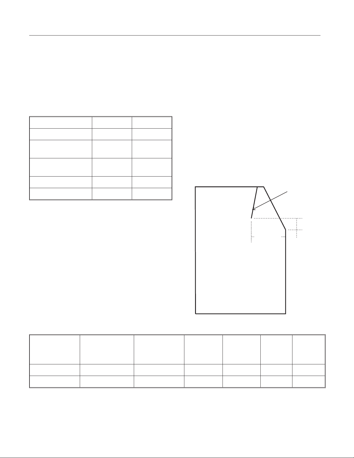
Note: Slope-front bins must have an internal baffle.
Scotsman BH900 and BH1000 have the required
baffle. Baffle must be approximately in the position
shown in the diagram below.
Baffle
Scotsman assumes no liability or responsibility of
any kind for products manufactured by Scotsman
that have been altered in any way, including the
use of any parts and/or other components not
specifically approved by Scotsman.
BASIC INFORMATION
Model Number Dimensions
WxDxH
(w/o bin)
CME1856WS-32 48½“x24"x28” 208-230/60/1
CME1856WS-3 same 208-230/60/3
*Condenser only @90/70
Basic Electrical
(volts/Hz/phase)
12.0"
Side View
Condenser
Water
Supply
GPH 107* 60 30 40
GPH 107* 60 20 30
Refrigerant
Charge
R-404A
Minimum
Circuit
Ampacity
Maximum
Fuse Size
4.0"
If the numbers on the nameplate are different than the above, use the nameplate’s information.
The stacking kit required to place two like model cubers together is: KSCME6-LG-B.
November 2001
Page 2
Page 3
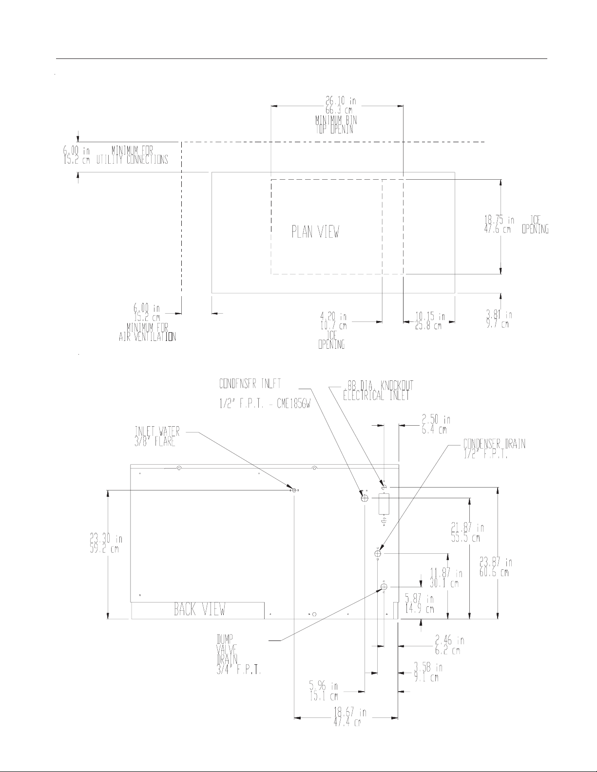
Ice Machine Layouts
CME1856W
November 2001
Page 3
Page 4
CME1856W
Pre-Installation
Other Applications:
Check sales literature for additional information.
Electrical:
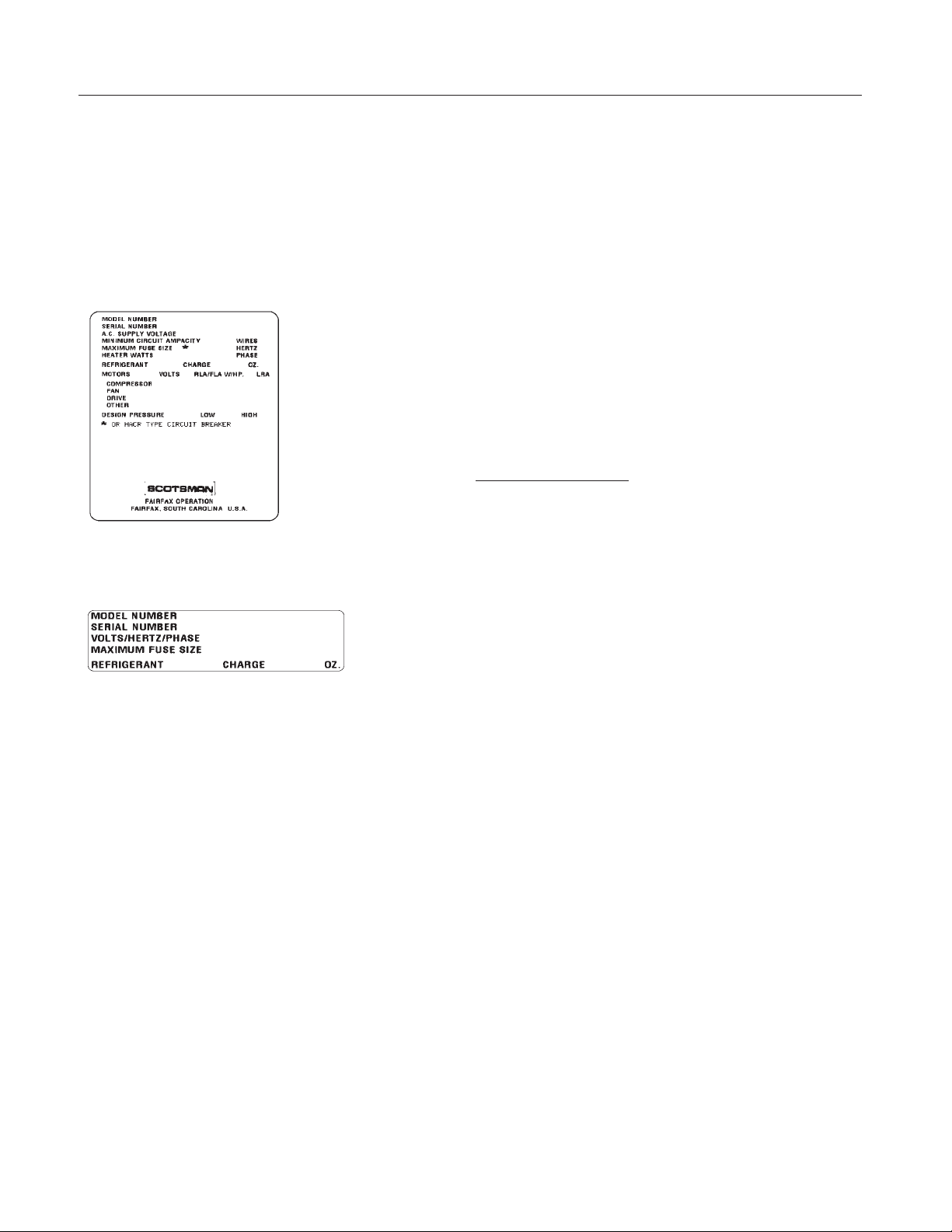
Check the nameplate for electrical requirements.
The nameplate is located on the back of the ice
machine. If the information on the nameplate is
different from other published information, go by
the nameplate data.
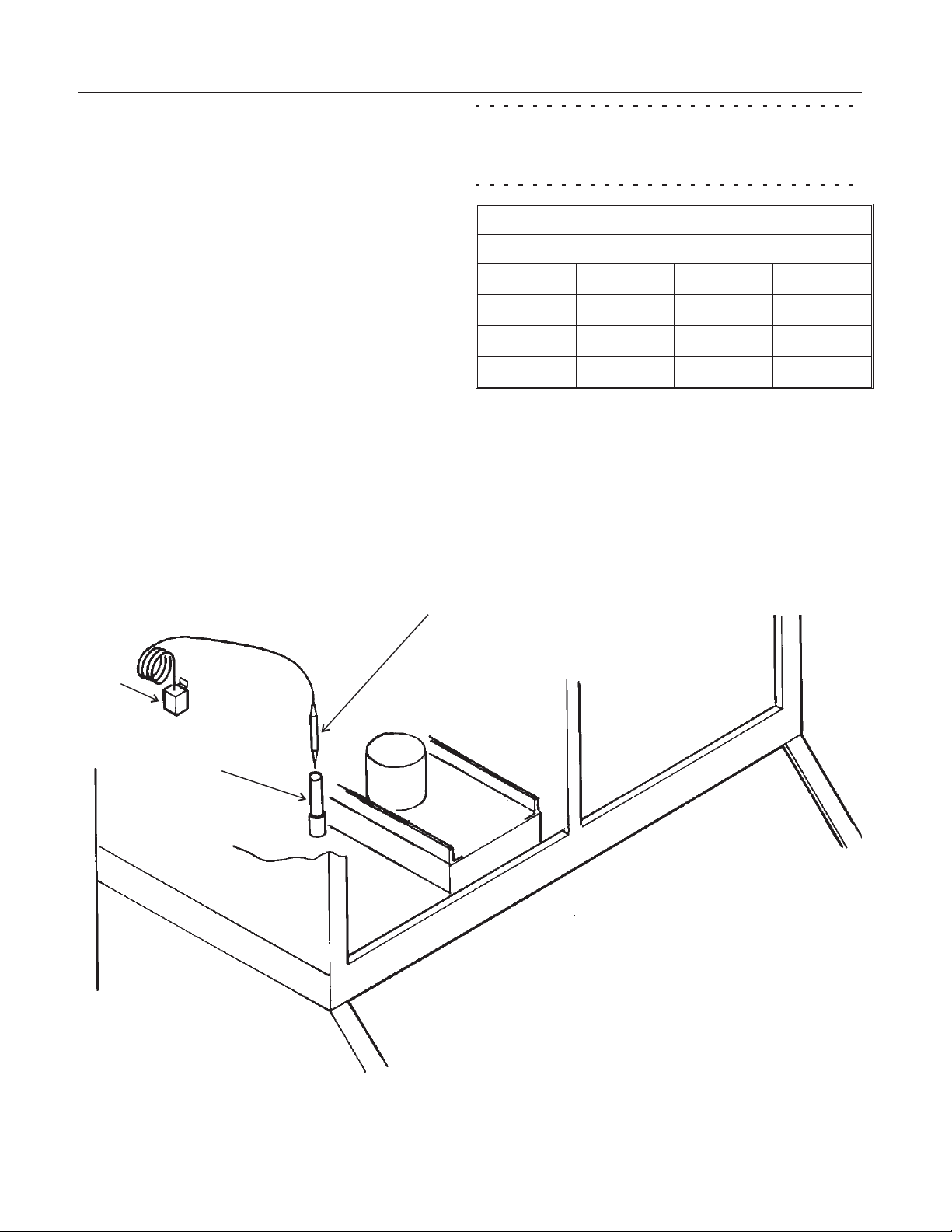
While the model and
serial number are on
the nameplate, a
serial number plate is
located at the front of
the machine, behind
the left front panel
and to the right of the
purge valve.
Nameplate
Serial Number Plate
Water:
There is no such thing as pure water. All water
contains some impurities. There are two ways
water carries the impurities: suspended and
dissolved. Suspended solids can be filtered out.
Dissolved solids must be diluted or treated. Water
filters are recommended to remove suspended
solids. Some filters have treatment in them for
suspended solids. Check with a water treatment
service for a recommendation.
Cube Ice machines use more water than what
ends up in the bin as ice. While most water is used
during ice making, a portion is designed to “rinse"
out the water system to keep hard water scale
from clogging up the machine. That water rinse,
combined with water filters, prolongs the times
between needed water system cleaning.
Service Technicians
come set from the factory with at a “Standard”
water rinse. Standard water rinse is designed to be
compatible with typical water conditions. The
ReliaClean™ water system provides an
adjustment method so the amount of water rinsed
out of the machine per cycle can be changed. If
the prior ice machine worked acceptably well with
the local water conditions, leave the machine at
the factory setting. If severe water conditions are
present, and water filters do not solve the problem
acceptably, adjust the machine to use more water.
If water conditions are excellent, adjust the
machine to use less water. See the Adjustments
section.
: All models covered here
Note: Water use adjustments are customer
convenience adjustments; they are NOT factory
defects and are NOT covered by warranty.
November 2001
Page 4
Page 5
Location & Assembly
CME1856W
Locate the ice machine indoors. A 6 inch minimum
clearance on the back and left sides is required for
the proper operation and service of this machine.
Unpacking and Assembly:
Begin with unpacking the ice storage bin. Remove
the carton, and using part of the carton as a
cushion, tip the bin on its back to remove the skid
and attach the legs or casters. Note: Stacked
applications may not use casters.
Return the bin to an upright position. Check the bin
top gasket for gaps and tears, fill any in with food
grade sealant prior to placing the ice machine on
the bin.
Note: If recycling a prior bin, be sure that the bin
top gasket is in good condition or seal the ice
machine to the bin with food grade sealant.
Level the top edge of the bin front to back and left
to right.
If the ice machine has not been unpacked, do so
now. Remove the carton from the skid. Remove
shipping straps.
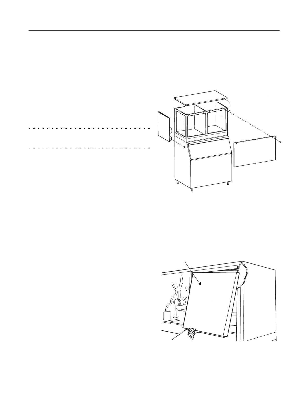
Cabinet Panel Removal:
1. Remove the front panel by removing the two
screws connecting the front panel to the machine.
2. Lift up at the front edge and push the top panel
back until it releases from the tabs connecting it to
the back panel.
Remove the front and left panels. Remove the
compressor shipping brackets and all packaging
materials.
After all packing materials have been removed
from the ice machine, lift or hoist the machine onto
the bin. Align the sides and back of the machine
with the sides and back of the bin.
Secure the ice machine to the bin with the two
metal straps and 4 bolts provided.
3. Remove two screws at the front of each side
panel, and pull them forward until they release
from the tabs connecting them to the back panel.
Evaporator Cover:
To Remove
Evaporator Cover:
Push Up and Tilt Out
November 2003
Page 5
Page 6
CME1856W
Bin Control: Installation
The bin control is a thermostat. It must be field
installed after the ice machine has been placed on
the bin.
Before starting, remove the left front panel and any
baffle in the bin.
1. Locate bin thermostat bulb.
2. Route bulb thru routing tube (located between
the compressor and the reservoir).
3. Locate bin thermostat bracket.
4. Carefully position the thermostat bulb on the
bracket (see the diagram on the next page).
5. Fasten the bracket to the bottom of the ice
machine with the two 3-pronged knobs supplied
with the unit.
6. Pull back into the ice machine any excess
capillary tubing.
7. Return the baffle to the bin and continue with
the installation.
Note: If the machine is located at an altitude higher
than 2,000 ft., adjust the thermostat by removing
the plastic cover and rotating the adjustment screw
per the table.
Bin Thermostat Altitude Correction Table
CW Turns of Range Screw (under plastic cover)
Feet Turns Feet Turns
2000 55
4000 160
6000 250
o
o
o
8000 340
9000 385
10000 405
o
o
o
Use This Table to Adjust Thermostat
Bin
Thermostat
Body
Bin Thermostat Bulb
Thermostat Bulb
Routing Tube
Route Bin Thermostat Bulb Into Bin
November 2001
Page 6
Page 7
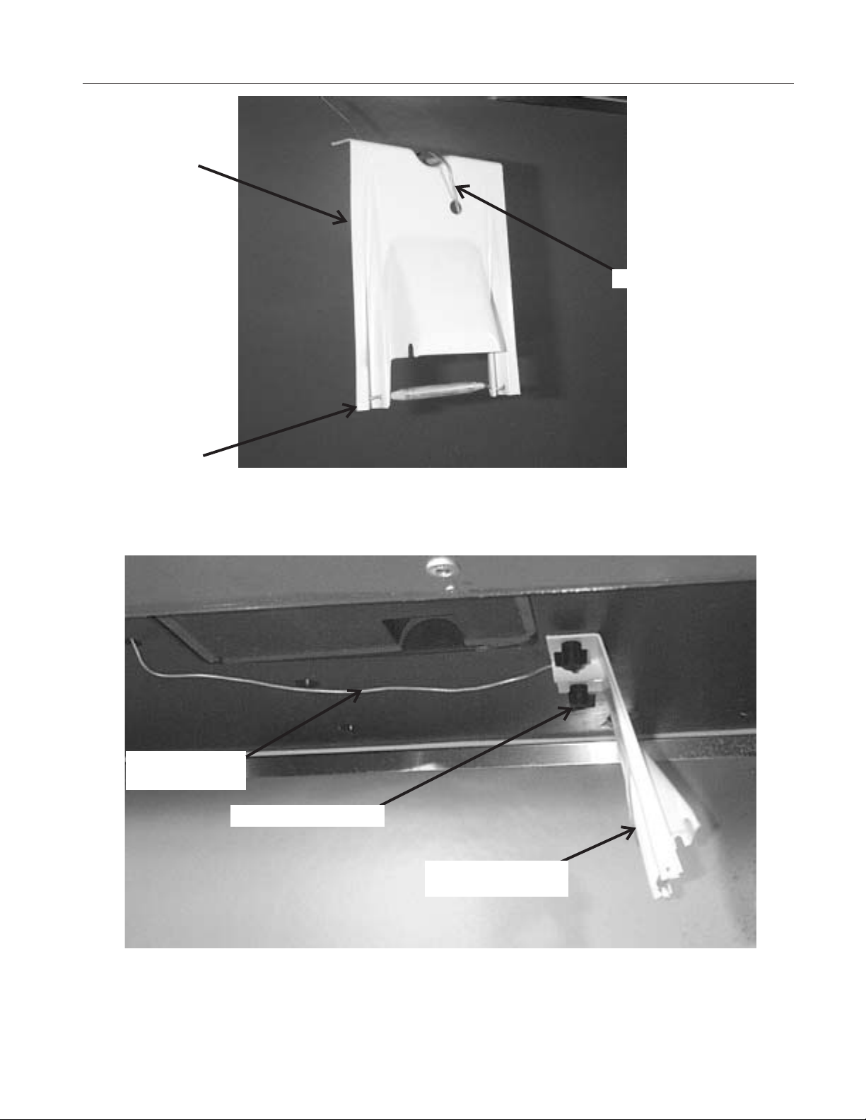
Bin Control
Bin Thermostat
Bracket
CME1856W
Bin Thermostat Capillary Tube
Mount Bulb Here
Minimize Excess
Tube in Bin
Attach Thermostat Bulb to Bracket
Three-Pronged Knob
Thermostat and
Bracket
Attach Bracket to Bottom of Ice Machine
November 2001
Page 7
Page 8
CME1856W
For The Installer:
Cooling Tower Applications:
This unit requires no special modifications for use
on a cooling tower. However, the sizing of the
cooling tower requires the heat of rejection and the
pressure drop across the ice machine’s water
cooling circuit (water regulating valve and
condenser).
Heat of Rejection: 27,400 BTUH - Peak
·
Pressure Drop: 7 psi
·
Maximum water temp into condenser: 110oF.
·
Peak GPM at 110oF:9-10
·
GPH at 110/100: 372
·
GPH at 90/70: 107
·
GPH at 70/50: 59
·
October 2001
Page 8
Page 9
Electrical
CME1856W
All models must be installed with the correct wire
size and type per the National Electric Code.
Locate the nameplate on the back of the cabinet
and find the numbers for Voltage, Phase, Minimum
Circuit Ampacity and Maximum Fuse Size. Either
fuses or HACR type circuit breakers may be used.
The ice maker is designed to operate on its own
electrical circuit and must be individually fused.
Voltage variation must not exceed the limits listed
on page 2.
Electrical connections are made in the junction box
in the back of the cabinet.
1. Remove the junction box cover.
2. Knock out one hole for a field supplied strain
relief.
3. Install wires and strain relief per code.
4. Connect to wires and secure ground wire to
ground screw inside junction box.
All external wiring should conform to the national,
state and local electrical code requirements.
Usually an electrical permit and the services of a
licensed electrician will be required.
November 2001
Page 9
Page 10

CME1856W
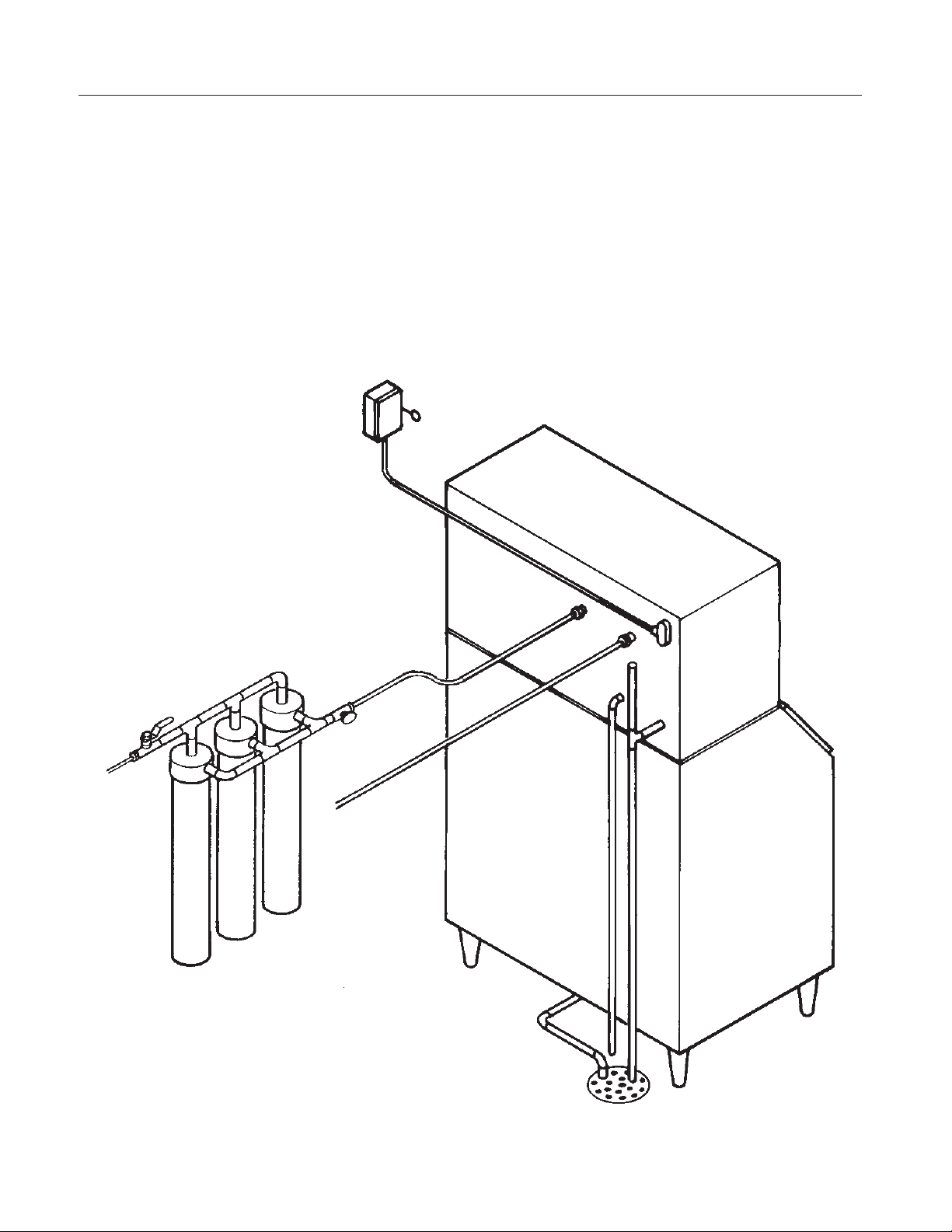
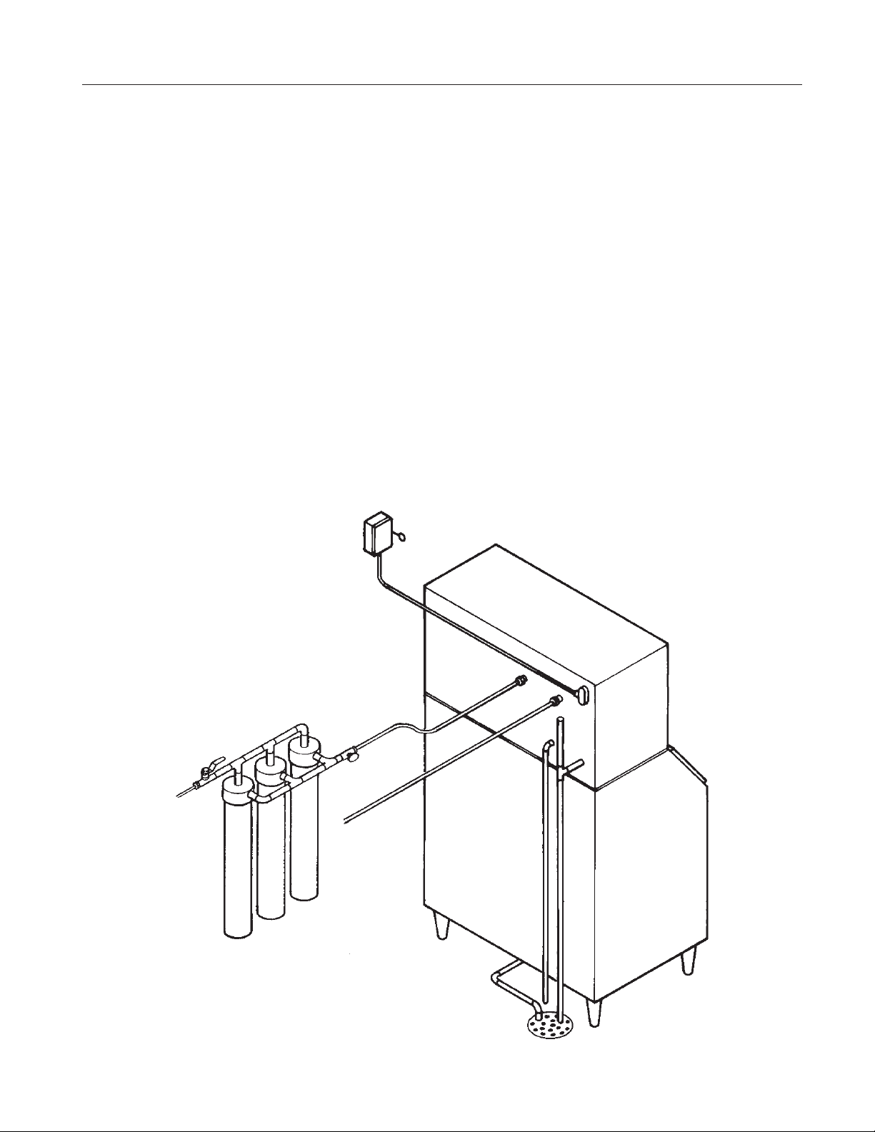
Plumbing
All models require an adequate potable water
supply, a condenser water supply and a gravity
drain. The recommendations for tubing are:
All Drain Tubing Material must be RIGID.
Flexible tubing will eventually kink and cause a
restricted drain.
Potable water supply to be
•
Condenser water supply to be ½" OD.
•
Reservoir drain to be
•
Condenser drain to be ½” OD, non vented
•
3
" OD.
8
3
" OD and vented
4
Note: When replacing a prior ice machine, do not
take a short cut and reuse the old inlet and drain
system. INSTALL A NEW SYSTEM.
Supply:
All models have 1 potable water supply connection,
3
" male flare at the back of the cabinet. Connect
a
8
to cold potable water that has adequate pressure.
Note: Using water supply tubing smaller than
3
"
8
will cause severe operational issues.
The water cooled condenser requires an additional
supply line.
Water Filters:
The water filters must flow at least 2.7 GPM or they
will cause severe operational issues. Check with
the filter manufacturer. When replacing a prior ice
machine, do NOT assume that the water flow
capacity of the filter will be adequate. Filtering the
condenser water supply is not recommended.
Drain:
3
Connect a
" drain tube to the reservoir drain
4
fitting at the back of the cabinet. Use only RIGID
TUBING. Flexible tubing may be easily kinked or
become cracked.
The reservoir drain tube must be vented at the
back of the cabinet. Use an 18" high vent.
Connect a ½” drain tube to the condenser drain at
the back of the cabinet. Do not vent this drain.
The ice storage bin will have a drain out the back
or base, depending upon the model.
The drains for the ice machine and the ice storage
bin must be SEPARATE or the ice machine’s
drain water may run into the bin and MELT THE
ICE.
Insulation is recommended for the ice machine
reservoir and bin drains.
Follow all applicable codes
November 2001
Page 10
Page 11

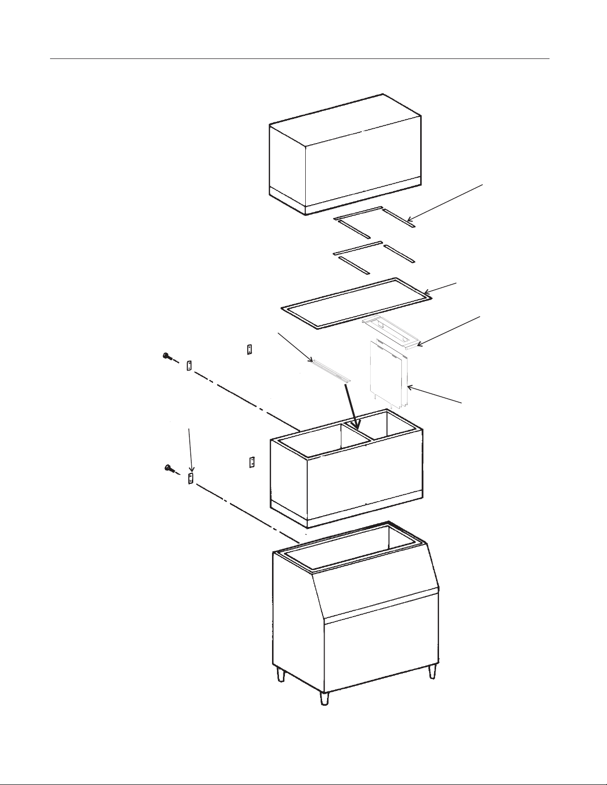
Stacking Kit - KSCME6-LG-B
CME1856W
Only like models may be stacked. Begin after the
bottom unit has been placed on the ice storage bin
and secured. Stacking requires heavy duty leg kits.
Casters are NOT recommended.
Note: Instructions are for either model.
Bottom Machine:
1. Remove front panel, left side panel, and top
panel.
2. Remove & discard top cover from over the
freezing compartment.
3. Install gasket materials to freezing
compartment:
Cut about 22" of gasket material from the roll in the
kit. Apply it to the back side top edge of the
freezing compartment.
Cut two lengths of gasket material to fit the right
side top edge of the freezing compartment and
apply them.
4. Place a bead of food grade sealant to the top of
the back wall’s gasket.
5. Place the shield bracket (has a large hole in the
center) from the kit over the center of the freezing
compartment.
Insert the tabs of the bracket into slots on the back
of the unit.
6. Secure bracket at the front with screws from the
kit.
7. Hang the plastic shields from the bracket
installed in the prior step. Use the slots in the
shields to hang them from the stainless steel
hooks.
Note: The notch in the bottom of the shield goes to
the front.
11. Remove two existing screws and secure the
bracket to the: freezing compartment, back panel
and front channel with the 2 existing screws and 1
large and 4 small screws from the kit.
Both Machines:
12. Place the top ice machine onto the bottom one.
Secure together with hardware from the top
machine. Remove left front and left side panels.
13. At the back of the ice machines, on the
compressor end, remove the upper knock-out from
the bottom machine and the lower knock out from
the upper machine.
14. Place a strain relief (from the kit) into each
hole.
15. Insert wire harness from kit thru strain-relief
and hole in upper corner of the lower ice
machine’s back panel.
NOTE: Harness is marked which end goes to
which machine.
Bottom Machine:
16. Remove harness from controller terminal 7 and
bin thermostat.
17. Route wire harness in lower ice machine to the
controller. Connect to terminal #7. Plug the two
free wires onto the thermostat terminals #1 and #2.
18. Return left side panel to its original position on
the lower ice machine.
Top Machine:
19. Remove harness from controller terminal 7.
20. Route wire harness thru upper unit’s lower
knock-out hole and strain relief and continue
internally to the controller. Plug wire onto terminal
7 of the controller.
Note: The tabs on the shields must fit inside the
ice outlet port.
8. Check the position of the shields. They must
move freely and be vertical.
Note: The suction line may need to be moved
slightly so the tubing clears the bracket & shields.
9. Place a bead of food grade sealant onto the top
left edge of the freezing compartment.
10. Install the front-to-back support bracket over
the left edge of the freezing compartment.
November 2001
Page 11
21. Return all panels and covers to their normal
positions.
22. Complete the balance of the installation.
Service Notes:
A. The shields must be positioned so they hang
vertically and move freely left to right. Their
purpose is to guide the ice past the bottom
machine’s evaporators and into its cube port.
B. The drain lines from each ice machine must be
kept separate.
Page 12
CME1856W
Stacking
Gasket on Plastic
Walls of Lower Unit
Gasket for Metal
Edges of Bottom
Unit
Front-to-Back
Support Bracket
Mounting Straps
and Hardware
Shield Hanger
Bracket
Shield
November 2001
Page 12
Page 13

After Utility Connections
1. Wash out the bin. If desired, the interior of the
bin could be sanitized.
2. Locate the ice scoop (if supplied) and have it
available for use when needed.
3. Go thru the final check list (below).
Final Check List:
___ 1. Is the unit located indoors in a
controlled environment?
___ 2. Has all the plastic covering the panels
been removed?
___ 3. Has the correct electrical power
(voltage and phase) been supplied to
the machine?
___ 4. Have all the water supply connections
been properly made with the correct
size tubing?
CME1856W
___ 5. Have all the drain connections been
properly made?
___ 6. Has the unit been leveled? Level the
unit at the bin.
___ 7. Have all unpacking materials been
removed?
___ 8. Is the water pressure adequate?
___ 9. Is the machine secured to the ice
storage bin?
___ 10. Is the bin control system been properly
installed?
___ 11. Have the drain connections been
checked for leaks?
___ 12. Has the bin interior been wiped clean or
sanitized?
___ 13. Have any water filter cartridges been
replaced?
___ 14. Check all refrigerant lines and conduit
lines, for vibration or rubbing and
possible failure. Adjust as needed.
___ 15. Proceed to Initial Start Up.
November 2001
Page 13
Page 14

CME1856W
Component Location and Function
Reservoir: Contains the water used to make ice.
Water Inlet Valve: Opens to allow water into the
reservoir.
Evaporators/Freezing Compartment: Location of
the evaporators. Ice forms on the evaporators and
is released when warmed up during the harvest
cycle. The freezing compartment is fully insulated
for maximum efficiency.
Cube Deflectors: The slots in the inclined
deflectors let the water falling from the evaporators
back into the reservoir, but when ice falls during
harvest, the ice slides off into the bin.
Water Pump: Forces the water from the reservoir
to the top of the evaporators. The motor is kept
separate from the water to minimize contact with
moisture.
Hot Gas Valve: Closed during freeze, it opens
during harvest to divert hot discharge refrigerant
gas into the inlet of the evaporators.
Purge Valve: Opens during the first part of
harvest, when the water pump restarts the water in
the reservoir is diverted to the drain.
Water Cooled Condenser: A counter-flow
cupro-nickel condenser. Supply water is heated by
refrigerant gas until the gas condenses.
Water Regulating Valve. Controls the amount of
water flowing into the condenser to maintain a
constant discharge pressure during the Freeze
cycle.
November 2001
Page 14
Page 15

System Controller
CME1856W
Indicator Lights:
Bin Full: On when bin is full, goes on and
•
off as ice falls during a harvest cycle.
Freeze: On when the unit is in the Freeze
•
cycle, blinks when a freeze cycle is pending.
Harvest: On when the unit is in the Harvest
•
cycle.
Clean: On when the unit is in the Clean
•
cycle.
Off: On when the unit has been switched off,
•
blinks when the machine is preparing to shut
off.
Water: On when the controller has identified
•
a problem with the water system.
Refrigeration: On when the controller has
•
identified a problem with the refrigeration
system.
LOW VOLTAGE IN/OUT
WATER VALVE
HOT GAS VALVE
PURGE VALVE TIMER
CONTACTOR COIL
Cycle Definitions:
Freeze: The refrigeration system is
•
operating to remove heat from the
evaporators. The compressor and water
pump are ON.
Harvest: The refrigeration and water
•
systems are operating to harvest the ice
cubes. While the compressor is on for the
full cycle, the water pump will be off at the
beginning and the inlet water valve will
switch off before the end.
Clean: Water valve opens to fill the
•
reservoir. The Water pump starts. The Clean
indicator light is switched ON. A manually
initiated rinse cycle flushes the system.
89
HI VOLTAGE IN/OUT
WATER PUMP
STACKING and/or
THERMOSTAT
RESERVOIR & DISCHARGE
LINE THERMISTORS
ICE SENSOR
ICE SENSOR
RESERVOIR WATER
LEVEL SENSOR
FACTORY USE
7
6
5
4
3
2
1
PUSH BUTTON
CONTROL SWITCHES
INDICATOR LIGHTS:
BIN FULL
FREEZE
HARVEST
CLEAN
OFF
DIAGNOSTIC LIGHTS:
WATER
REFRIGERATION
November 2001
Page 15
Page 16

CME1856W
Initial Start Up
1. Remove the front and left side panels.
2. Check that the compressor shipping brackets
have been removed.
3. Connect electrical power.
4. Locate the Controller and note which color
housing it has, blue or black.
5. When a controller receives power for the first
time after having been switched Off it goes through
a start up routine, the routine used depends on
the color of the housing. Black housings
flash on & off. Blue housings
blink while the Freeze and Clean lights are
displayed (to verify it’s using the correct program),
after that the Bin Full and Off lights will be on for a
few seconds. The Bin Full light then switches off.
6. After the start up routine the Off light on the
controller will be glowing.
7. Open the water supply valve(s).
8. Push and release the Freeze cycle push button
(the Freeze indicator light will blink until the
compressor starts).
Initial Start (30 seconds)
•
The Freeze light will blink.
•
The hot gas solenoid valve will be open.
•
The purge valve will be open
•
The water pump will be on
•
After 30 seconds, the hot gas valve closes
•
The purge valve will shut and the inlet water
valve will open to fill the reservoir.
•
The compressor starts.
Note: Three Phase Units (Scroll Compressor). If at
start up the compressor makes a louder than
expected noise and does not begin to cool the
evaporators or suction line, the compressor motor
is likely running backwards. See page 21.
Freeze Cycle
The Freeze indicator light will be on. The unit will
be in a Freeze cycle for many minutes.
•
The pump will stop for a few seconds a few
minutes into the freeze cycle
•
The freeze cycle will continue until the water
level in the reservoir drops to its factory set
point, the first time that happens the water
valve will re-fill the reservoir. The second
time it starts the Harvest Cycle.
: the two red lights
: all lights
Harvest Cycle:
The Harvest indicator light will be ON,
•
The hot gas valve will open.
•
The purge valve will be open for 74 seconds.
•
The pump is off, it will restart in < 74
•
seconds.
The purge valve closes.
•
The Inlet water valve opens for a short time
•
The Bin Full indicator light will go on and off
•
as ice falls from the evaporators.
Note: Up to 72 hours of compressor run time may
be needed to achieve rated performance.
9. After about 6 minutes (first cycle after any
restart) the machine will return to a freeze cycle.
Note: After the first harvest, the controller will
adjust the harvest time as needed to release all
ice.
10. The reservoir refills at the beginning of Freeze.
11. Fill out the Customer Evaluation and Warranty
Registration. Send it to Scotsman.
12. Return all panels to their normal positions.
13. Inform the user of the location and telephone
number of the local service company. Inform the
user of the required maintenance of the machine.
Operational Notes:
1. The machine will only shut off on Bin Full at the
end of the Harvest Cycle after the bin fills. That
last harvest cycle will be about 5 minutes long.
2. After switching off on Bin Full, if ice is removed
from the bin, the machine will not restart until it has
been off for 4 minutes. If the Freeze button is
pushed, the machine will restart immediately.
3. If the bin controls sense a bin full signal before
any water is used (float stem up), the machine will
shut off on bin full.
4. When shutting off, the compressor will run for 30
seconds (everything else is off) and then switch
off.
November 2003
Page 16
Page 17

Adjustments
CME1856W
If there was a problem during Initial Start Up:
If a diagnostic light came on, check the following.
1. Water.
A water error could have been determined by the
System Controller if the inlet water valve does not
fill the reservoir or if the water pump does not start
and lower the water level in the reservoir. If either
condition is found, the water error light will be
switched on and the machine will Shut Down.
2. Refrigeration.
A refrigeration error could have been determined
by the System Controller if the water temperature
did not drop during the freeze cycle. The
Controller will next check the compressor
discharge temperature. If the discharge
temperature is too low, the refrigerant error light
will be switched on, and the machine will Shut
Down.
Note: The machine can be reset and restarted by
pushing and releasing the Off push button switch,
and then pushing and releasing the freeze push
button switch.
Thermostatic Expansion Valve:
The TXV is not adjustable, do not attempt to adjust
it.
How to Adjust the Amount of Water Purge
Adjustment is done by use of the control buttons
on the System Controller. Examine the next
section to become familiar with the System
Controller before beginning.
1. If the machine is on, push and hold the OFF
button for more than 3 seconds, then release it.
This switches the machine Off.
2. Push and hold the OFF button for more than 3
seconds (just until all Lights flash on) then release
it. Do not hold it in it too long.
3. Examine the green Lights. They should have all
flashed once, then certain ones will have turned on
to indicate which purge level the machine is set at.
There are 5 levels of purge available:
1. Maximum Purge is when All 5 lights are
•
ON. Use for extreme water conditions. Note:
This setting may extend the Harvest cycle
and reduce capacity.
2. Heavy Purge is when these 4 lights are
•
ON: Freeze
moderate to severe water conditions. This
setting may extend the Harvest cycle and
reduce capacity.
•
3. Standard Purge (factory setting) is when
these 3 lights are ON: Harvest
Use for typical water conditions.
•
4. Moderate Purge is when these 2 lights
are ON: Clean
conditions.
•
5. Minimum Purge is when this light is ON:
Off
. For excellent water conditions.
Adjust by pushing and releasing the Freeze button.
Pushing and releasing the Freeze button increases
the purge one level up to the maximum, then it
goes to the minimum.
, Harvest, Clean,Off. Use for
, Clean,Off.
,Off. This is for good water
Typical Ice Level When Unit Shuts Off
November 2001
4. The machine will automatically restart after 60
seconds of no switch inputs, or restart the machine
by pushing in and holding the Off button for more
than 3 seconds, then releasing it. The unit will then
be Off. From there the machine may be placed in a
freeze cycle by pushing and releasing the Freeze
button.
Page 17
Page 18

CME1856W
S
How To Operate The Controller
The Controller is a microprocessor based device
that receives input from several sources and
switches various components on and off.
Its manual control is thru the use of the Push
Button Control Switches
1. Freeze Button. Pushing and releasing this
button starts or restarts the machine. The System
Controller remembers what cycle it was last in and
returns to that cycle.
2. Harvest Button: Pushing and releasing this
button will cause the machine to go directly to a
Harvest Cycle. Can be done from Freeze or Off.
The machine will switch Off at the end of the
Harvest cycle.
3. Clean Button: Pushing and
releasing this button will cause the
machine to empty the reservoir, refill
and leave only the water pump on for
circulation of ice machine cleaner.
After the ice machine cleaner has
circulated for about 10 minutes a
second push of this button will switch
on the rinsing system to flush out the
dissolved scale and ice machine
cleaner.
89
4. Off Button: Pushing and releasing
this button will switch the machine OFF
at the end of the next cycle. If the
button is pushed and HELD for more
than 3 seconds, the unit will switch off
immediately.
To Reset: First push and release the
Off button, then push and release the
Freeze button.
7
6
5
4
3
2
1
PUSH BUTTON
CONTROL SWITCHE
INDICATOR LIGHTS:
BIN FULL
FREEZE
HARVEST
CLEAN
OFF
DIAGNOSTIC LIGHTS:
WATER
REFRIGERATION
November 2001
Page 18
Page 19

CME1856W
How The Electronic Cuber Works
This section is intended for the technician. It is not necessary for the normal operation and maintenance
of the machine.
Refrigeration System:
Freeze Cycle: Heat is removed from the water and
discharged out the condenser during the freeze
cycle. As liquid refrigerant passes thru the
Thermostatic Expansion Valve, it enters the top of
the evaporators, and ice will form at the top first.
Water Cooled Condenser
Distributor
Thermostatic Expansion Valve
When cubes need to be released (Harvest) the Hot
Gas Valve is opened and Hot discharge gas flows
directly from the compressor to the evaporator
inlets.
This warms up the evaporators and the surface of
the ice frozen to the evaporator surface melts. Ice
then falls into the bin.
Hot Gas Header
Discharge Line
Compressor
Liquid Line
Evaporator
Heat
Exchange
Evaporator
Accumulator
Hot Gas
Valve
Evaporator
Refrigeration Schematic
November 2001
Page 19
Page 20

CME1856W
How The Electronic Cuber Works
Water System:
Freeze:
The water pump forces water to the top of the
evaporators. The un-frozen water falls thru the
cube deflectors and back into the reservoir. As
water is turned into ice, the water level in the
reservoir falls, and the machine will re-fill the
reservoir once during the freeze cycle.
At the point where the cubes are fully formed, the
water level sensor indicates to the System
Controller that it is time to begin the Harvest cycle.
Harvest:
At the beginning of Harvest, the water pump shuts
off and the purge valve opens. The purge valve
remains open for 74 seconds. No water will drain
until the water pump restarts. The water pump will
start at a variable time depending upon the amount
of water rinse that has been set.
After the purge valve has closed, the inlet water
valve opens and water flows into the ice machine.
The water valve will NOT be open the complete
length of the harvest cycle.
The inlet water valve will “top off” the reservoir at
the beginning of the next freeze cycle.
The Controller operates the ice machine by
monitoring several input measures and switching
various loads on and off.
Controller Inputs:
1. Reservoir water temperature. This is
measured by a thermistor located in the water
pump outlet.
2. Discharge line temperature. This is measured
by a thermistor located on the compressor
discharge line.
3. Water level. This is measured by an infrared
sensor and float. The float rises and falls with the
water level, and switches the sensor on and off as
it moves.
4. Bin fill level. The thermostat in the bin is used
to switch the machine on and off. The electric eyes
in the cube outlet port will also control the machine
if the bin thermostat sticks in an ON position.
5. Time to last cube. This is measured by a set of
electric eyes in the cube outlet port. During harvest
individual ice cubes pass between the
photo-electric eyes and the interruption of the
signal from the emitter to the receiver signals to
the controller that ice is being released.
5. Time. The controller measures and compares
how long it takes for various events to happen. It
stores that data for future reference.
Controller Outputs:
A. 24 volt:
•
•
•
•
B. High Voltage
•
•
November 2001
Page 20
1. Lights
2. Inlet water valve
3. Hot Gas Valve
4. Contactor Coil
1. Water Pump
2. Purge Valve
Page 21

Startup: Three Phase Compressor
All three phase motors can operate in either rotor
rotation direction depending upon how power is
supplied to the motor.
However, a THREE PHASE scroll compressor
will not work properly if run BACKWARDS.
If a three phase ice machine’s compressor is
making an unusually loud noise and the ice
machine does not appear to be refrigerating the
water, it’s likely that it’s running backwards.To
fix this two of the three compressor motor leads
need to be reversed.
1. Disconnect electrical power.
Electrical Shock Hazard
CME1856W
Disconnect electrical power
before beginning
2. Remove left front panel.
3. Pull off compressor terminal cover.
4. Locate terminals, switch any two wires.
5. Return compressor terminal cover to its original
position.
6. Reconnect electrical power.
7. Push freeze button, compressor will start and
soon begin to cool the evaporators.
November 2001
Page 21
Page 22

CME1856W
Technicians Only: Freeze Cycle Sequence
Assuming the machine has been operational, the
Freeze cycle begins with the end of the Harvest
Cycle:
Water Inlet Valve is Closed
•
Water Pump is ON
•
Compressor is ON
•
Hot Gas Valve is Open
•
System Controller Operation, Beginning freeze:
1. Switches on Freeze indicator light and shuts off
the hot gas valve.
2. Opens the water valve to top off the reservoir.
The controller checks that water fills the reservoir,
if it does not fill up within 250 seconds, the
controller shuts the machine down. It will
automatically try to restart in 20 minutes.
3. Measures and stores the discharge
temperature.
4. If the discharge temperature exceeds the design
maximum, shuts the machine down on a
Refrigeration Error.
5. Checks for a “bin full" signal throughout the
cycle.
6. Measures the reservoir water temperature. If the
machine is operating correctly, the reservoir water
temperature will fall at a standard rate. The
Controller will be checking to see if the water
temperature fall matches that rate.
8. As the machine makes ice, the water level in the
reservoir will ultimately fall to the Harvest Level.
The first time that happens per freeze cycle the
inlet water valve is re-opened and the reservoir is
refilled. The next time it happens, the unit will go
into a harvest cycle.
Note: If the freeze cycle exceeds the preset
Maximum (36 minutes), the Controller will Shut
Down the machine and switch on the Refrigeration
Light.
9. The end of Freeze cycle will see the machine in
this state:
Water level = below harvest position
•
Water inlet valve will be off
•
Water pump will be ON
•
Compressor will be ON
•
Hot gas valve will be off
•
At this point Harvest begins and the System
Controller switches the Harvest indicator light ON.
Restarts:
If the machine is restarting after it has shut off
because the bin was full, the first freeze cycle
sequence is like this:
1. Purge valve is open.
2. Pump starts.
3. Purge valve closes.
If not, it re-checks the discharge line temperature.
If too low, it Shuts Down on a Refrigeration Error. If
the discharge temperature is acceptable, the water
system is checked by shutting off the water pump
and determining if the water level goes up enough.
If it does not, the inlet water valve will open again
to fill it. If, after restarting, the water level does not
drop, it is assumed that there is a water pump
problem and the machine Shuts Down on a Water
Error.
If the water level does “measure up" the water
pump is restarted and the Controller then
measures how long it takes to lower the water
level. If the water level does not fall, the machine
Shuts Down on a Water Error.
7. Once per freeze cycle the machine will shut off
the water pump. It only does this when the water
temperature reaches a preset minimum. The pump
will only be off for a few seconds.
November 2001
Page 22
4. Water valve opens to fill the reservoir.
5. Compressor starts.
Note: If there is a power interruption, after power is
restored the machine will restart, go thru a brief
Freeze cycle and go thru a 6 minute Harvest cycle.
Error Restarts:
The machine automatically attempts to restart 50
minutes after a shut down. If another problem
occurs in the next cycle, the machine will attempt
one more restart. If another problem occurs in the
next cycle, the machine will shut off and must be
manually reset.
Page 23

Technicians Only: Harvest Cycle Sequence & Other Notes
CME1856W
Harvest
The Purge Valve will be open for 74 seconds.
The water pump shuts off, it will restart before 74
seconds, the restart time is based on the Purge
Level Setting.
The pump restarts and pumps water out of the
reservoir until the purge valve closes.
The inlet water valve will stay on for about 30
seconds to add enough water to assist with
harvest.
The Hot Gas Valve will be open for the entire
length of the Harvest Cycle.
During the Harvest Cycle, ice will be falling from
the evaporators and between the ice sensor’s
photo-electric eyes. The Controller monitors how
long the ice falls and uses that time to determine
the next harvest cycle’s length.
The first Harvest after a restart will take about 6
minutes to establish a base line, then the time it
took to release that ice is used to determine the
next harvest cycle’s length.
The maximum harvest time is 14 minutes.
If no cubes fall (or are sensed) by the end of the
Maximum Harvest Time, the machine senses a
Refrigeration error. If the next cycle also produces
a Refrigeration error, the machine will shut down.
Note: The last Harvest cycle before shutting off on
Bin Full will be 6 minutes long.
Note: The machine will not restart for 4 minutes
after switching off on Bin Full, unless the Freeze
button is pressed.
Bin Full: The controller will switch on the
compressor for 30 seconds after 12 hours of off
time to keep refrigerant out of the compressor oil.
Single Phase: Power Interruptions:
If the power supply to a single phase unit is
interrupted for less than a second, a time delay
relay will keep the compressor from restarting until
30 seconds have passed. Because the controller
should still be operating.
Continuous Run Time
A unit that operates 24 hours a day 7 days a week
is too small for the user’s needs. To maintain
harvest integrity, the controller will extend the
harvest time to 6 minutes every 15th consecutive
harvest cycle.
Bin Thermostat
:
In normal ambients the thermostat will react to ice
on the bulb in a few seconds. Reaction after
removal will take about a minute under normal
conditions, and longer in colder rooms.
Stacked Units:
If the bottom unit is in harvest and receives a
signal from the top unit that it is also in Harvest,
the bottom unit will stay in harvest for about 6
minutes.
If the bottom unit is shut off, but its controller still
has power, the top unit may continue to operate. If
the bottom unit’s power is shut off, the top unit will
shut down on bin full at the end of the next cycle. If
the top unit’s power is shut off, it does not impact
the bottom unit.
An error shut down on one unit does not affect the
other.
Either one may be switched off at the controller
without impacting the other.
Diagnostic Light Code Table
If a Diagnostic
Light
Blinks once and
repeats
Blinks twice and
repeats
Blinks three
times and
repeats
Is ON all the
time
Water Light Refrigeration
Light
Water pump will
not start
Lack of water fill No harvest of
not used High Discharge
Water valve
leaking thru
rapidly
Very long ice
harvest
ice
Temperature
Check for low
discharge
temperature or
long freeze
cycle
Both ON all the
time
November 2001
Page 23
Check for thermistor set unplugged
or failed
Page 24

CME1856W
Sanitation and Cleaning
It is the User’s responsibility to keep the ice machine and ice storage bin in a sanitary condition.
Without human intervention, sanitation will not be maintained. Ice machines also require occasional
cleaning of their water systems with a specifically designed chemical. This chemical dissolves mineral
build up that forms during the ice making process.
Sanitize the ice storage bin as frequently as local health codes require, and every time the ice machine
is cleaned and sanitized.
The ice machine’s water system should be cleaned and sanitized a minimum of twice per year.
In Place Cleaning of the Ice Machine Water
System:
1. Remove all ice from the bin.
2. Remove the front panel.
3. Push and release the Harvest button (this releases
any ice that may be on the evaporators and warms
them up).
4. Wait for the machine to finish the Harvest cycle
(the machine will stop).
5. Remove the the insulated plastic evaporator cover,
the two inner splash panels (part number 02-3680-01
and the one above it), both cube deflectors, and the
ice sensors. Place the splash panels and the cube
deflectors in a separate container. Place the ice
sensors in the reservoir, but be sure that the ends of
the connecting wires are not in the water.
6. Push and release the Clean button. The Clean
indicator light will be blinking, and the pump will
restart.
7. Pour 24 ounces of Scotsman Ice Machine Cleaner
into the reservoir water. Return the evaporator cover
to its normal position.
8. Mix a solution of 8 ounces of Scotsman ice
machine cleaner and 1 gallon of warm (95-115oF.)
water. Use the solution to scrub the splash panels
and cube deflectors in the separate container.
Scotsman Ice Machine
Cleaner contains acids.
Acids may cause burns.
If concentrated cleaner
comes in contact with skin,
flush with water.
If swallowed, do NOT
induce vomiting. Give large
amounts of water or Milk.
Call Physician
immediately. Keep out of
the reach of children.
9. After the ice machine cleaner has circulated for 10
minutes, push and release the Clean button. This
starts the rinsing process. The Clean indicator light
will be ON. Note: The rinse process flushes any
residual cleaner out of the ice machine’s water
system.
10. Continue the rinsing process for 20 minutes, then
push the off button to switch the machine off.
11. Go to the next step to sanitize the machine or go
to step 19 to finish the cleaning process.
12. Mix 2 gallons of Sanitizer solution. Follow local
codes for Sanitizer.
Note: A possible sanitizing solution may be made by
mixing 1 ounce of liquid household bleach with 2
gallons of warm (95-115oF.) potable water.
13. Push and release the Clean button again.
14. Pour 24 ounces of Sanitizer solution into the
reservoir water.
15. After the solution has circulated for 10 minutes
push and release the Clean button. This starts the
rinse process. Sanitize the ice storage bin while
waiting.
16. Continue the rinsing process for 20 minutes, then
push the off button to switch the machine off.
17. Remove the evaporator cover and spray or wash
all interior surfaces of the freezing compartment
including the evaporator cover with sanitizer solution.
18. Thoroughly immerse the splash panels and cube
deflectors in the sanitizing solution.
19. Return the ice sensors, splash panels and cube
deflectors to their original positions.
20. Return the evaporator cover to its original
position. Push and release the Freeze button.
21. Return the front panel to its normal position and
secure it to the machine with the original screws.
November 2001
Page 24
Page 25

Additional Maintenance
CME1856W
To Properly Place the Evaporator Covers
Removal:
1. Remove front panel.
2. Push up on evaporator cover and swing out the
base.
3. Use the finger holes to pull the lower inside
cover down and swing it out from the machine.
4. Pull upper inside cover out from behind the
pump hose.
Note: ALL COVERS MUST BE PROPERLY IN
PLACE or the MACHINE WILL MALFUNCTION.
Insert Bottom Tabs in 5th
Slot of Cube Deflectors
Push and Hold
Activate Purge
To drain reservoir (if desired):
1. Remove front panel.
2. Push and hold the Off button until the machine
shuts off.
3. Push and hold the Clean button for 3 seconds.
The water pump will discharge water out the open
purge valve.
4. When the reservoir is empty release the Clean
button and push and release the Off button.
5. Push and release Freeze button to restart.
6. Return the front panel to its original position.
To Sanitize the Ice Storage Bin
1. Remove all ice.
2. Remove baffle.
the Clean
Button for 3
Seconds to
Valve
Replacement:
1. Return upper inside cover to its original position.
2. Using finger holes to control the part, insert the
two tabs on the bottom of the lower inside cover
into the 5th slot of each cube deflector.
3. Push down and insert upper edge of the lower
inside cover into the slot on the bottom of the
evaporator bracket.
4. Insert evaporator cover into plastic slot at the
top of the compartment and then place the lower
end onto the reservoir wall.
November 2001
Page 25
Or: Drain the Reservoir by Holding Purge
Valve Open While in a Clean Cycle
3. Switch ice machine OFF or wait for it to be in a
cleaning cycle.
4. Mix a 1 gallon solution of warm (95-115oF.)
water and sanitizer. Follow local codes for
sanitizer.
5. Wash or spray the entire interior of the ice
storage bin with the sanitizer solution. This
includes the bottom of the ice machine and the
inside of the door, the door gaskets (if any) and
door frame.
6. Pour excess sanitizer into the bin to flush the
drain system.
7. If the approved sanitizer requires a rinse, rinse
all interior surfaces with potable water.
Page 26

CME1856W
Additional Maintenance: Water Distributors
It may become necessary to remove the water
distributors from the top of the evaporator and
clean (de-mineralize) them outside of the ice
machine.
1. Remove front panel.
2. Push and release the OFF button.
3. Remove the evaporator covers.
4. Pull the tab at the front of the evaporators
forward and lift the water distributors up until they
clear the tab.
Water
Distributors
distributors in or with a solution of Scotsman Ice
Machine Cleaner and warm potable water.
10. Return the water distributors to their normal
installed position.
11. Push and release the clean button to flush the
water system.
12. After the machine stops, push and release the
Freeze button.
Check That Water
Channels Are Clear
5. Repeat for all evaporators and distributors..
6. Slide the left and right groups of distributors
forward until the center manifold is accessible.
7. Remove the distributors from the manifolds.
Manifold
8. Examine the top of the evaporators. The Water
Distribution Channels must be free from mineral
build up. If build up is evident, scrub the channels
with Scotsman Ice Machine Cleaner and a plastic
bristle brush.
13. Replace the evaporator covers.
Insert Bottom Tabs in 5th
Slot of Cube Deflectors
14. Replace the front panel.
9. Examine the water distributors. Although they
are made of a material that is resistant to mineral
build up, some may be present. Soak or scrub the
November 2001
Page 26
Page 27

Additional Maintenance: Inlet Water Valve Screen
CME1856W
The inlet water valve has a screen on its inlet side
to keep debris from flowing into the valve. In some
cases, this screen may become clogged or
restricted by debris build up. Check for the proper
water flow:
Flow rate is 2.7 G.P.M.
1. Remove front panel.
2. Obtain a 16 ounce cup and a watch.
3. Pull the water discharge tube out of the
reservoir and place it in the cup.
4. Push and release the Harvest button.
5. If working properly, the water valve will fill an 16
oz cup in about 3 seconds. Be prepared to push
the Off button! If it does not, the water valve inlet
or other water device is restricted.
To Check the Inlet Water Valve Screen.
1. Disconnect the electrical power.
2. Shut off the water supply.
3. Remove the left front panel.
4. Unplug the electrical connection of the inlet
water valve.
Water Level Sensor
The water level sensor contains two photo-electric
eyes and each eye has an emitter and a receiver.
For proper operation the receiver must be able to
sense the signal of the emitter.
Dust can reduce the efficiency of the photo-electric
eyes. To clean them:
1. Remove front panel.
2. Push and hold the Off button until the machine
stops.
3. Remove the screw holding the right reservoir
cover to the reservoir and lift the cover up.
4. Reach in and hold the float while pulling the float
stem up and out of the float.
5. Reach in under the pump mounting cover and
locate the two tabs of the water level sensor.
Squeeze them towards each other and pull the
sensor up and out of the pump mounting cover.
6. Disconnect the wire harness from the water
level sensor.
7. Remove two screws holding the dust cover to
the water level sensor.
5. Remove the screws holding the inlet water valve
to the cabinet.
6. Remove outlet tube from inlet water valve.
7. Rotate inlet water valve from inlet fitting and
remove valve from machine.
8. Examine the inlet screen, if dirty, brush off
screen.
Note: Screen is not replaceable, and may only be
removed by taking off the covering bracket. The
bracket forms part of the inlet water system, and
must be water tight to the valve body, removal is
not recommended.
9. Reverse to reassemble.
Dust
Cover
8. Clean the 4 lenses with a soft tissue or cotton
swab.
Clean
Lenses
Clean
Lenses
Water Level Sensor, Dust Cover Removed
9. Reverse to reassemble.
November 2001
Page 27
Page 28

CME1856W
Additional Maintenance: Ice Sensors, Condenser
The ice sensors use a system of infrared emitting
and receiving components to sense the build up of
ice in the bin. They are located at the bottom of the
ice outlet port. They must be free of mineral build
up to function properly. To check:
1. Remove front panels.
2. Push and release the harvest button.
3. Wait for the machine to stop.
4. Remove the evaporator cover.
5. Locate the front ice sensor.
Push the sensor from the front (at the wire area) to
the back until it releases from the holder.
6. Locate the back ice sensor Pull on the
rectangular tab to release it from its mounted
position.
7. Examine the bottom of the brackets, there are
two sensors in each bracket, check that they are
clear of mineral build up. They may be wiped clean
with ice machine cleaner to assist in removal of the
build up.
Note: Do NOT use abrasive materials or cleaner
on the ice sensor lenses. A soft toothbrush works
well to get into the hard to reach spots.
8. Reverse steps 1-6 to reassemble.
To Clean the Water Cooled Condenser
Under typical water conditions the condenser will
not require any maintenance. However, if the
water supply contains a large amount of minerals,
the water cooled condenser may become coated
internally with scale. The symptom of a dirty
water cooled condenser is abnormally high
water use.
Do NOT perform this procedure too frequently or
on a clean condenser. Premature failure of the
condenser may occur.
1. Remove left side and front panels.
2. Shut machine off.
3. Shut water supply to condenser off.
4. Disconnect condenser water inlet from water
regulating valve.
5. Rig a submersible water pump ina5to8gallon
bucket with a hose on the outlet of the pump.
6. Connect the hose to the condenser inlet.
7. Connect another hose to the condenser outlet
and route it to the bucket.
8. Mix an acid solution such as Scotsman ice
machine cleaner and hot water. Follow the mixing
instructions provided with the acid. Pour or mix the
solution in the bucket. Do NOT use straight acid.
9. Start the pump and operate it, circulating the
acid solution through the condenser for about an
hour.
November 2001
Page 28
Page 29

Service Diagnosis: Diagnostic Light Analysis
Problem or Symptom Possible Cause Probable Correction
Machine is off Bin is full Use some ice
Bin thermostat is closed Check thermostat, unplug the connection to
the controller at terminal 7 and wait 4 minutes.
If the machine starts, the thermostat was
closed and needs to be adjusted or replaced.
If the Bin Full light does NOT go out check the
ice sensors. See next page bottom.
Power is off, check Lights. If all Lights are out, check power supply,
restore power if off
Transformer is open If all Lights are out and there is power, check
transformer output for 24 vac
Unit manually switched off Push and release Freeze button
Unit has Shut Down Check for Refrigeration or Water Error
CME1856W
Unit is off and the
Water Diagnostic Light
is ON or BLINKING
Unit is off and the
Refrigeration
Diagnostic Light is ON
or BLINKING
Water supply inadequate Check water Light, if the Light blinks 2 times
and repeats, check the water inlet valve.**
Water pump malfunction Check that pump hose is attached and if
pump is plugged in and working.
Water level sensor may
have failed.
Low discharge or long
freeze cycle
Harvest problem Check refrigeration Light. If the Light blinks
High Discharge Temp Check refrigeration Light. If the Light blinks 3
Check float stem, reset machine. If it will not
reset or gives another water error and all else
is OK, replace the water level sensor.
Check refrigeration Light. If the Light is
glowing, there is a probable refrigeration
problem - Check water supply and/or water
regulating valve.
once and repeats, look for a harvest problem.
where some cubes were sensed.**
Check refrigeration Light. If the Light blinks
two times and repeats, look for a harvest
problem. - no cubes sensed**
times and then repeats, check for a reason for
high discharge temperatures.
Unit does not go into
harvest - exceeds
maximum freeze time
Exceeds max harvest time Check for cause of long harvest cycle**
Unit runs and both
Diagnostic lites are
ON
Same, only 1 light on Reservoir temp. wrong Check water temp. and sensor.
* Machine may be reset by pushing and releasing the Off button, then pushing and releasing the
Freeze button. ** See following pages
Temperature sensors out
of range
November 2001
Page 29
Push and release Off button. Push and
release Freeze button. Check operation.
Push cube size float down, check operation.
Replace the temperature sensor set (water
and discharge).
Page 30

CME1856W
Service Diagnosis
Problem or Symptom Possible Cause Probable Correction
Unit is off because of a
“Harvest Problem”
Cubes are too large Water sensor float is
Cubes are too small Not enough water Check for leak in reservoir
Ice sensors did not sense
ice falling, unit stayed in
harvest until the maximum
harvest time ran out.
Ice sensors or Controller
may have failed.
Other components may
have failed
sticking.
Inlet water valve leaking
thru (slowly)
Check ice sensors. If the bin full light is on or
blinking the ice sensors may be dirty. Clean if
dirty. The board and ice sensors may also
need to be checked for proper operation.
Check evaporators for lime scale build up.
Clean evaporators and bin controls if dirty.
Push and release Off button. Push and
release Freeze button. Check machine
operation. Check if ice is made and harvests.
See “Unit does not shut off” below..
Check the next page
Check/clean
Check hose from water valve for slow drip.
Replace valve if dripping.
Check/clean water sensor eyes
Check for a leak thru the purge valve
Low ice capacity Water regulating valve
pressure adjusted too high
Low refrigerant charge Check system. If there is a low charge, find
Too much water Check for inlet water valve leak thru
Unit does not shut off Ice sensing system may
have failed.
Adjust water regulating valve to 240 PSIG of
discharge pressure in freeze
the leak, recover the refrigerant, repair the
leak, replace the dryer, evacuate and weigh in
the nameplate charge.
Check controls. Unplug thermostat and check
bin full light, if off, place something between
the electric eyes. The bin full light should
begin glow steadily after 20 seconds of
continuous blockage. If not, check operation
of electric eyes by unplugging #4 and jumping
out the two pins on the controller (touch the
tool to the cabinet to discharge static
electricity before contacting the controller). If
the bin full light blinks, replace the bin
controls. If it does not blink, replace the
controller. Note: Leaving #4 unplugged and
jumped for 20 seconds will shut the machine
down on a bin full (at the end of the harvest
cycle). It will restart after 4 minutes or may be
reset by pushing the Freeze button.
November 2001
Page 30
Page 31

Service Diagnosis: Components
Problem or Symptom Possible Cause Probable Correction
CME1856W
Pump motor does not
turn
Hot Gas Valve does
not open.
Hot Gas Valve leaks
thru (warm tube
temperatures on both
sides of valve during
freeze)
Water Inlet Valve does
not open
Water Inlet Valve does
not flow enough water
Open motor windings, or
seized bearings
No power to pump Check electrical connections. In Freeze, the
Open solenoid coil. Replace hot gas valve
Stuck valve Replace hot gas valve
No power to coil in Harvest Check wire connections, if ok, replace
Mechanical problem in
valve
Open solenoid coil Replace valve
Stuck valve Replace valve
No power to valve (best
checked at the beginning
of Freeze)
Restriction in water supply Check water filters and/or inlet screen.
Replace pump
pump should have power to it. If not, replace
the Controller.
Controller
Replace valve
Check wire connections, if ok, replace
Controller
Water Inlet Valve
leaks thru
Compressor runs, but
loudly & no ice is
made
Compressor does not
work
Mechanical problem in
valve
Three phase compressor is
phased wrong
Unit in Clean cycle Push and release Freeze button.
Contactor coil open Replace contactor
Open starting components Check and replace
Open windings Check and replace compressor
Internal valve failure Replace compressor
Replace valve
Switch any two wires to the compressor
November 2001
Page 31
Page 32

CME1856W
Service Diagnosis
Problem or Symptom Possible Cause Probable Correction
Poor Harvest Scale in water system. Clean water system.
Low Capacity
Water or Air Temperatures too
cold
Low system charge Recover and weigh charge.
Hot gas valve does not open Check for power to the coil, if
Water regulating valve does not
maintain enough pressure (in
freeze) or leaks through (in
harvest)
Extreme hot location Relocate the cabinet
Overcharge of refrigerant Recover, evacuate and weigh in
Hot gas valve leaks thru, unit off
on refrigeration error
Check temps. Unit cannot
operate with water and air
temps below stated limits.
there is power, replace the hot
gas valve
Replace the water regulating
valve
the nameplate charge
At the end of the freeze cycle,
there should be a definite
difference in temperature
between the inlet and outlet of
the Hot Gas Valve. If not,
replace the hot gas valve
Compressor cycles on and off Compressor overheats Low on refrigerant, locate leak,
recover refrigerant, repair leak,
replace drier, evacuate and
weigh in the nameplate charge.
TXV superheat too high, check
charge, if charge is OK, replace
TXV
Mechanical fault with
compressor, replace
compressor
Internal relief valve opened,
check for cause of high
discharge pressure
November 2001
Page 32
Page 33

Operational Characteristics: CME1856W
Cycle Times (minutes):
70oF. indoor air, 50oF. water 90oF. indoor air, 70oF. water
Freeze 12 - 13 minutes 12 to 14 minutes
Harvest 3 to 4 minutes 2.5 to 3 minutes
System Pressures (PSIG):
70oF. indoor air, 55oF. water 90oF. indoor air, 70oF. water
Suction: End of Freeze 23 PSIG 24 PSIG
Suction: Peak in Harvest 79 PSIG 84 PSIG
Discharge: 5 minutes into Freeze 250 PSIG 250 PSIG
Discharge: Minimum in Harvest 140 PSIG 140 PSIG
CME1856W
Number of Evaporators:
6
•
Refrigerant Charge
60 ounces of R-404A
•
Compressor Type
•
Three Phase: Copeland Scroll ZS30K4E-TF5-230
•
Single Phase: Copeland Scroll ZS30K4E-PFV-230
Typical Compressor Amps,
single phase
•
freeze 19.6
•
harvest 22.5
three phase
•
11 to 9 freeze
•
11 harvest
Typical Harvest Ice Weight
•
20 - 21 lb.
Hi Pressure Cut Out - Automatic Reset
•
Hi Pressure Cut Out - 400 PSIG
•
Hi Pressure Cut In - 300 PSIG
Low Pressure Cut Out - Automatic Reset
•
Cut Out - 15 PSIG
•
Cut In - 30 PSIG
14
12
10
8
6
4
2
0
Beg 2
mins3mins5mins
Three Phase Amp Draw
1st
fill10mins
Freeze Cycle
End Hvst End
Hvst
Harvest
November 2001
Page 33
Page 34

CME1856W
Suction Pressure
90
80
70
60
50
PSIG
40
30
20
Suction Prssure
10
0
Time
Pressures During Freeze and Harvest at 70oF Air and 50oF Water
November 2001
Page 34
Page 35

Removal and Replacement
CME1856W
Inlet Water Valve
1. Remove the left front panel.
2. Shut off the water supply.
3. Push and release the OFF button.
4. Pull the wire harness off the inlet water valve.
5. Remove screws holding the inlet water valve to
the cabinet.
6. Pull the valve away from the cabinet and
disconnect the outlet tube.
7. Unscrew the water valve from the water inlet
tubing. Hold the barbed inlet fitting and rotate the
valve.
8. Reverse to reassemble.
9. Push and release the Freeze button.
10. Replace the front panel.
Purge Valve Timer
Water Pump
1. Disconnect the electrical power.
2. Remove the front panel.
3. Unplug water pump from its electrical
connection.
4. Remove 1 plastic bolt and the reservoir cover.
5. Lift water pump up and disconnect outlet tube.
6. Pull float ball from float stem (it is a snap fit).
Pull stem out.
7. Locate water level sensor mounting tabs,
compress together to release sensor from bracket.
8. Remove water pump brackets from pump.
9. Reverse to replace.
10. Replace front panel.
11. Re-connect electrical power.
The purge valve timer is sensitive to electrostatic
discharge. Be certain to touch a grounded surface
before touching this component. Do the same
when handling the replacement part.
1. Touch a grounded surface.
2. Remove left front panel.
3. Disconnect electrical power.
4. Remove high voltage box cover.
5. Locate timer board at the back of the high
voltage box.
6. Unplug all the wires to the board.
7. Compress each of the four stand-off posts to
release the board from the stand-offs.
8. Remove the board from the unit.
Reverse to reassemble.
November 2001
Page 35
Page 36

CME1856W
Removal and Replacement
Purge Valve
1. Disconnect electrical power.
Electrical Shock Hazard.
Disconnect electrical
power before beginning
service.
2. Remove left front panel.
3. Unplug wire harness from purge valve coil.
4. Locate and remove the two screws securing the
purge valve to the machine.
5. Pull the inlet and outlet hoses off the purge
valve and remove it from the machine.
6. Reverse to reassemble. There are no internal
parts available for this valve.
Water Level Sensor/Float Stem
Note: Only one float stem fits this product. Be
SURE that this is the correct one.
1. Disconnect the electrical power.
2. Remove the front panel.
3. Remove 1 plastic bolt and the reservoir cover.
4. Pull float ball from float stem (it is a snap fit). Pull
stem out.
5. Locate water level sensor mounting tabs,
compress together to release sensor from bracket.
6. Remove harness from sensor.
7. Reverse to replace.
8. Replace front panel.
9. Re-connect electrical power.
Water Level Sensor
1. Remove front panel.
2. Push and hold the OFF button. Release it when
the machine stops.
3. Trace wire harness from water level sensor to
the Controller (#2). Unplug the harness from the
controller.
4. Lift the pump and mounting plate up enough to
remove the float from the stem.
5. Remove two screws holding the sensor to the
pump bracket and lift the sensor up and out of the
machine.
6. Reverse to reassemble.
November 2001
Page 36
Page 37

Controller Features & Last Error Recall
CME1856W
Last Error/Diagnostic Light Recall
To recall the last error on the blue housing CM
controller:
1. Switch the unit OFF by holding the OFF button
for longer than 3 seconds.
2. Hold the Off button down again until the Purge
Setting indicators (Green Lights) are on.
3. Push and release the Harvest button.
The last error code stored in the controller will
•
be displayed and the purge setting will
disappear.
Push the Harvest button again and the
•
second-to-last error code will be displayed.
Pushing the Harvest button again will display
•
the last error code again. Only two error
codes are available for display.
If no error code exists, no code will be
•
displayed and there will be NO LIGHTS
showing.
To return from the display of the last error, do
nothing for 60 seconds or push and release the Off
button.
3
Program ID
The blue housing controller will display a code at
power up that indicates which ice machine model it
has been programmed for.
The code is based on the green lights that are
displayed.
1. At power up all lights flash ON once to indicate
that the controller has passed its internal
self-checks.
2. Immediately after that the program code will be
displayed for 20 seconds or until a button is
pushed.
Note: The proper program code for this machine is
glowing Freeze and Harvest lights. Do NOT
operate this machine if the wrong code is
displayed.
3. If no button is pushed after 20 seconds the
machine will display the Off light and is ready for
switch inputs (push and release Freeze to start
making ice).
Note: The Red Diagnostic Lights will be FLASHING
while the program ID is displayed.
After returning from the display of the last error (Off
light glows), the machine may be returned to the ice
making process by pushing and releasing the
Freeze button.
November 2001
Page 37
Page 38

CME1856W
Removal and Replacement: System Controller
1. Disconnect the electrical power.
2. Remove the front panel.
3. Remove mounting screw holding controller to
cabinet.
4. Touch a metal surface to discharge any static
electricity.
5. Pull controller out slightly and unplug all
electrical connections.
6. Carefully remove the new controller from its
packaging.
7. Plug all electrical connectors into the new
controller.
8. Re-attach the controller to the cabinet.
9. Switch on the electrical power. All Lights should
lite up.
10. Push and release the Freeze button.
11. Replace the front panel.
Electric Eyes (Ice Sensors)
These must be replaced as a set.
1. Remove both front panels.
2. Push and release the Off button.
3. Remove evaporator cover.
4. Remove lower inner splash panel.
5. Locate the back electric eye. Pull out on the
rectangular tab until the sensor is free of its
installed position.
6. Unplug the back sensor from its wire harness.
7. Unplug the front sensor its wire harness
Back Sensor
8. Locate retainer clip in front sensor holder. Pull
clip up and out of the holder.
9. Push in on the place where the wires enter the
sensor until it releases from the holder.
10. Twist the sensor 90 degrees and pull it up and
out of the machine.
11. Reverse to reassemble. Be sure that the color
codes of the connecting wires match.
November 2001
Page 38
Front Sensor Holder
Page 39

Removal and Replacement:
CME1856W
Discharge Line Temperature Sensor
1. Remove front panel, push and release the Off
button.
2. Remove top and left side panels.
3. Locate discharge line sensor. It is attached to
the discharge line of the compressor, 6" from the
compressor discharge port.
4. Un-snap the clip holding the sensor to the
discharge line.
5. Trace the sensor wires back to the controller,
they are plugged into #5 with the water
temperature sensor, and must be replaced with it.
6. Reverse to replace, be sure that the discharge
line sensor is 6" up from the compressor discharge
port. The discharge line sensor is marked with
yellow tape.
Note: Route wires so they do NOT contact the
discharge line.
Water Temperature Sensor
Note: This sensor is replaced as a set with the
Discharge Temperature Sensor.
Important Compressor Information
The compressor should not be replaced until it has
been determined that it has definitely failed. If it will
not start check the starting components first. If the
machine has low capacity, check for proper
charge, TXV operation, hot gas valve leak thru or
inlet water valve leak thru.
The metal bracket in front of the compressor must
be removed to access the compressor.
Note: This machine uses a Copeland Glacier scroll
compressor, which has the following unique
operating characteristics:
1. Do NOT bypass the low pressure control and
operate the compressor in a vacuum. The vacuum
can cause the fusite pins to arc and fail.
Determine proper compressor operation by
eliminating other causes for low capacity: TXV, Hot
Gas Valve, or Inlet Water Valve. Finally compare
amp draw, it should be within 15% of what’s listed
on page 35.
2. Do NOT touch the top of the compressor. It is
same temperature as the discharge line!
1. Remove left front panel.
2. Push and release Off button.
3. Remove 1 plastic bolt and the reservoir cover.
4. Locate water temperature sensor (inserted into
pump discharge hose).
5. Pull out to remove.
6. Trace back to system controller, unplug from #5.
7. Remove the Discharge Line temperature
sensor.
8. Reverse to reassemble.
Note: Do not push sensor tip in too far. There
should be about an 1/8" gap between the tip and
the inner wall of the water discharge hose.
Burn Hazard
Compressor top is HOT!
Do NOT touch
3. Discharge and suction fittings are copper-plated
steel. Use a brazing rod with some silver content.
4. Three phase motors can operate backwards,
but this compressor can’t. See page 21.
5. The oil charge is fine if it is just below the
half-way mark on the sight glass.
6. Weigh the charge into the discharge side. The
compressor may not start if the charge is only
present on the high or low side. See page 42.
7. When recovering refrigerant, do NOT recover
only from the discharge side. Some refrigerant will
be left in the low side and will be a hazard if a
brazing torch is applied.
8. Use the metal mounts that were on the ice
machine, do NOT use the rubber mounts from the
replacement compressor.
November 2001
Page 39
Page 40

CME1856W
Removal and Replacement
Transformer and Compressor Starting
Components
Single phase compressors use a start relay, start
capacitor and run capacitor. All are located in a
sheet metal box to the right of the system
controller. The compressor contactor is also
located in that box.
1. Disconnect electrical power.
2. Remove front panel.
3. Remove 2 screws at the front edge of the metal
box, and pull the cover forward and out.
4. To check components, reconnect electrical
power.
Note: The contactor coil is 24 volt.
Evaporator Support Bracket
In the unlikely event that the evaporator support
bracket needs to be replaced, two people will be
needed.
1. Remove both front panels and the top panel.
2. Push and hold the Off button until the machine
stops.
3. Remove evaporator cover.
10. Check that all evaporators are properly seated
front and back.
11. Remove the wire ties, and return the splash
panels, hoses, and evaporator cover to their
normal positions. Check that water distributors are
in place.
12. Push and release the Freeze button to start the
machine.
13. Check operation.
14. Return the top and front panels to their normal
positions.
Refrigeration System Components
Due to the expected level of training and
experience of a refrigeration mechanic, detailed
instructions regarding the replacement of
refrigeration components will not be presented.
However, critical items will be noted here.
Evaporators
In the unlikely event that an evaporator may need
to be replaced, do NOT braze the evaporator joints
when the evaporators are seated in the freezing
compartment, instead lift them up slightly so that
the joints to be brazed are above the top edge of
the freezing compartment.
4. Remove the interior splash panels.
5. Remove the hoses from the water distributors.
6. Use wire ties to hang the front of the
evaporators from the upper cross brace.
7. Place a clean rag under the planned cut point
and saw the old bracket in half and remove it.
8. While holding the bracket so that the right end is
higher than the left, insert the right end in the
vertical channel in the right side of the freezing
compartment.
Then, while the helper lifts the right-most
evaporator slightly, push the bracket in from below.
Keep doing this and push up on the left end of the
new bracket.
The freezing compartment walls may be pushed
apart slightly to make this easier.
9. Push up enough on the left end of the bracket
until it snaps into the vertical channel in the left
side of the freezing compartment.
November 2001
Page 40
Page 41

Refrigerant
1. This ice machine uses R-404A or HP62 as a
refrigerant. It has several unique characteristics.
A. It is a near-azeotrope, and must be liquid
charged.
B. It must use polyol ester refrigerant oil, and that
oil is very water absorbent. The system must not
be open for more than 15 minutes.
C. An electronic leak detector capable of locating
HFC-134a type refrigerant must be used to locate
refrigerant leaks.
D. A special HFC type liquid line dryer must be
used.
E. When brazing, a dry nitrogen purge is required.
F. When evacuating, use of an electronic micron
gage is recommend. Evacuate to 300 microns.
Recovering the Refrigerant
CME1856W
Because of the check valves, liquid refrigerant
must be recovered thru the liquid line valve, as
well as the low side access valve at the front of the
machine.
Access Valves:
1. Remove the stem cap and insert a 3/16" allen
wrench. Check that the valve is closed.
2. Remove the port caps and attach refrigerant
manifold hoses.
3. Open the valves and purge the hoses.
4. When service is complete, shut the discharge
access valve first. Then, with the machine running
and the middle hose outlet securely fastened to
the manifold or refrigerant tank (closed) open both
manifold valves. This allows any liquid refrigerant
in the discharge hose to flow thru the manifold and
into the suction side.
5. After the gages have equaled, shut the
manifold valves and the suction access valve.
6. Remove the gages and replace the stem and
port caps. Make certain that all caps are on tightly.
November 2001
Page 41
Page 42

CME1856W
Liquid Charging
Because R-404A is a near-azeotrope, only liquid
refrigerant can be used to recharge the
refrigeration system. To do that may take some
special techniques:
1. Use an electronic scale to measure the charge.
2. Place a drum or cylinder of R-404A on the
scale, valve side up (most R-404A disposable
cylinders have an internal dip tube and dispense
liquid refrigerant from the valve when it is upright check yours).
3. A refrigeration manifold should be attached to
the service access valves. Attach the charging
hose to the cylinder of R-404A. Open the cylinder’s
valve and purge the hose to the manifold.
4. Close the low side service access valve.
5. Open the discharge side manifold valve and
weigh in the name plate charge. After the charge is
weighed in, wait a few minutes and re-check the
scale.
6. If all of the refrigerant charge has not been
weighed into the discharge side, it must be
carefully added thru the low side. Close the
discharge service access valve.
Allen
Wrench
Torque Stem
to 6-8 ft. lb.
Torque Stem Cap to
8-12 ft. lb.
Torque Core Cap
to 7-12 ft. lb.
Access Valve
Low Side Access Valve
7. With a sight glass or charge faster in the hose to
the low side port, start the ice machine.
8. Open the low side service access valve.
9. Crack open the low side manifold valve and
watch the scale and sight glass. Open and close
the low side manifold valve to flow liquid into the
manifold but flash off to vapor before it enters the
suction side of the refrigeration system. This
should only be a few ounces at most.
10. After the scale = the correct charge, shut off
the valve on the refrigerant cylinder.
11. With the ice machine running and the
discharge access valve closed, open both manifold
valves to allow the refrigerant in the hoses to enter
the system.
12. Shut the suction service access valve.
13. Remove the refrigeration manifold gages.
14. Replace and tighten all caps.
Stem Must Be
Half-way Out
(after hose is
connected) to
Recover,
Evacuate and
Recharge
November 2001
Page 42
Liquid Line Access Valve
Page 43

CME1856W
S
Before Calling for Service
Check the following:
1. Has the water supply to the ice machine or building been shut off? If yes, the
ice machine will automatically restart within 25 minutes after water begins to
flow to it.
2. Has power been shut off to the ice machine? If yes, the ice machine will
automatically restart when power is restored.
3. Does the bin control have ice on it? If so, remove the ice and the machine
should start in a few minutes.
To Manually Reset the machine.
1. Remove the left front panel.
2. Locate the System Controller. If a red diagnostic light is glowing, note which
one and its blink rate. Then push and release the off button.
3. Push and release the Freeze button.
4. The machine should begin to operate. If
there is a lack of water it will soon shut off
again.
5. Return the front panel to its normal
position.
If the machine shuts down again, call for
service.
To Shut the Machine Off:
1. Remove the left front panel.
2. Locate the System Controller.
3. Push and hold the Off button for 3
seconds or until the machine stops.
89
7
PUSH BUTTON
6
5
4
3
2
1
System Controller
CONTROL SWITCHE
INDICATOR LIGHTS:
BIN FULL
FREEZE
HARVEST
CLEAN
OFF
DIAGNOSTIC LIGHTS:
WATER
REFRIGERATION
November 2001
Page 43
Page 44

CME1856W
Index
A
Adjust the Amount of Water Purge ································17
C
Cleaning of the Ice Machine Water System:····························24
Compressor Information ······································39
Cooling Tower ···········································8
Cycle Definitions: ·········································15
I
Indicator Lights ··········································15
L
Last Error Recall··········································37
O
Operational Characteristics ····································33
Operational Limits ·········································2
R
Reset ···············································18
S
Stacking ··············································11
Startup: Three Phase Compressor ································21
T
Thermostat Altitude Correction ··································6
W
Water Level Sensor ········································27
November 2001
Page 44
 Loading...