

Page 1

CME1202R & CME1402R
INTRODUCTION
To the owner or user: This service manual is
intended to provide you and the maintenance or
service technician with the information needed to
install, start up, clean, maintain and service this
ice system.
Table of Contents
FOR THE INSTALLER . . . . . . . . . . . . . . . . . . . . . . . . . . . . . . . . . . . . . . . page 2
BACK VIEW OF CABINET . . . . . . . . . . . . . . . . . . . . . . . . . . . . . . . . . . . . . page 3
ERC401 SPECIFICATIONS . . . . . . . . . . . . . . . . . . . . . . . . . . . . . . . . . . . page 4
FOR THE INSTALLER: Location & Assembly . . . . . . . . . . . . . . . . . . . . . . . . . . . page 5
FOR THE INSTALLER: Location & Assembly . . . . . . . . . . . . . . . . . . . . . . . . . . . page 6
FOR THE INSTALLER: Scotsman Remote Condenser . . . . . . . . . . . . . . . . . . . . . . page 7
FOR THE INSTALLER: Coupling Instructions . . . . . . . . . . . . . . . . . . . . . . . . . . . page 8
FOR THE ELECTRICIAN . . . . . . . . . . . . . . . . . . . . . . . . . . . . . . . . . . . . . page 9
FOR THE PLUMBER . . . . . . . . . . . . . . . . . . . . . . . . . . . . . . . . . . . . . . . . page 10
FINAL CHECK LIST . . . . . . . . . . . . . . . . . . . . . . . . . . . . . . . . . . . . . . . . page 11
INITIAL START UP . . . . . . . . . . . . . . . . . . . . . . . . . . . . . . . . . . . . . . . . . page 12
FREEZING CYCLE OPERATION . . . . . . . . . . . . . . . . . . . . . . . . . . . . . . . . . page 14
HARVEST CYCLE - HOT GAS BYPASS . . . . . . . . . . . . . . . . . . . . . . . . . . . . . page 15
COMPONENT DESCRIPTION . . . . . . . . . . . . . . . . . . . . . . . . . . . . . . . . . . . page 16
CLEANING . . . . . . . . . . . . . . . . . . . . . . . . . . . . . . . . . . . . . . . . . . . . . page 19
SYSTEM SPECIFICATIONS: CME1202 . . . . . . . . . . . . . . . . . . . . . . . . . . . . . . page 21
SYSTEM SPECIFICATIONS: CME1402 . . . . . . . . . . . . . . . . . . . . . . . . . . . . . . page 22
ADJUSTMENTS . . . . . . . . . . . . . . . . . . . . . . . . . . . . . . . . . . . . . . . . . . page 23
SERVICE DIAGNOSIS: Water . . . . . . . . . . . . . . . . . . . . . . . . . . . . . . . . . . . page 24
SERVICE DIAGNOSIS: Electrical and/or Adjustments . . . . . . . . . . . . . . . . . . . . . . page 25
SERVICE DIAGNOSIS: Refrigeration and/or Mechanical . . . . . . . . . . . . . . . . . . . . . page 26
SERVICE DIAGNOSIS: Bin Ice Level Control . . . . . . . . . . . . . . . . . . . . . . . . . . . page 27
REMOVAL AND REPLACEMENT . . . . . . . . . . . . . . . . . . . . . . . . . . . . . . . . . page 28
REFRIGERATION SERVICE . . . . . . . . . . . . . . . . . . . . . . . . . . . . . . . . . . . . page 31
LIQUID CHARGING . . . . . . . . . . . . . . . . . . . . . . . . . . . . . . . . . . . . . . . . page 32
Parts Lists and Wiring Diagrams are located in
the center of this manual, printed on yellow
paper.
This manual was printed on recycled paper.
Keep this manual for future reference.
Note this symbol when it appears in the
manual. It indicates a potential hazard.
January 1995
Page 1
Page 2
CME1202R & CME1402R
FOR THE INSTALLER
These machines will fit the following Scotsman ice
storage bins:
•• BH900
•• BH1000 (with bin top KBT21)
••BH1360
and will stack onto the following ice mach ines:
••CME1402 or CME1202 (use KSCMS4 8)
••MCM1462 or CMS1402B or CMS1202B (with
stacking kit KSCMS48)
Scotsman Ice Systems are designed and
manufactured with the highest regard for safety
and performan ce . They mee t o r exce ed th e
standards of U.L. , N.S.F., and C.U.L.
Scotsman assu mes no liability or res ponsib ility of
any kind for pro ducts manufact ured by Scotsman
that have been altered in any way, including the
use of any parts and /or oth er comp on ents not
specifically approved by Scotsman.
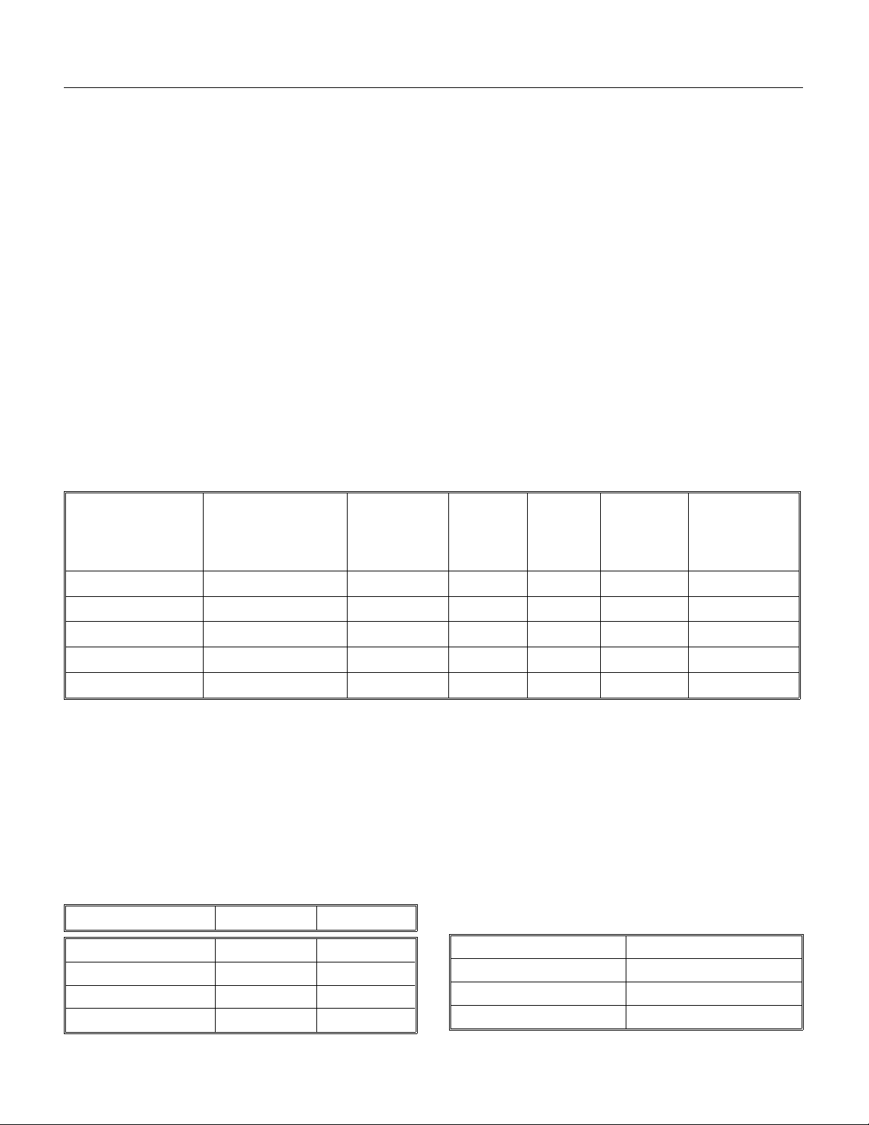
Model Number Dimensi ons
(without bin)
W" x D" x H"
Basic
Electrical
A remo te cond ense r a nd prech arged tubing kit are
required to asse mble this ice syst em.
The normal finish for the machin e is ename l
sandalwood . An op tio na l st ainless ste el p anel kit
(SPKCMS48 ) can be fie ld inst alle d. It cont ain s a
stainless stee l top, lef t sid e panel, an overlay righ t
sid e panel , and front pa nels.
Scotsman reserves the right to make design
changes and/or improvements at any time.
Specifications and designs are subject to change
without notice.
Minimum
Circuit
Ampacity*
Maximum
Fuse
Size+
Refrigerant
Charge**
R-404A
Condenser
Type
CME1402RE-3A
CME1402RE-32A
CME1202RE-3A
CME1202RE-32A
CME1202RE-6A
48 x 24
48 x 24
48 x 24
48 x 24
48 x 24
3
⁄8 x 271⁄2
3
⁄8 x 271⁄
3
⁄8 x 271⁄2
3
⁄8 x 271⁄
3
⁄8 x 271⁄
208-230/60/3 15.5 20 336 oz. Remote Air
208-230/60/1 22.9 30 336 oz. Remote Air
2
208-230/60/3 14.4 20 336 oz. Remote Air
208-230/60/1 20.9 30 336 oz. Remote Air
2
230/50/1 336 oz. Remote Air
2
* Minimum Circuit Ampacity is use d to determine wire size an d type per t he Natio nal Ele ctric Code.
+ Or HACR type circuit breakers.
** The unit is shipp ed with the ch arg e in th e rece ive r and, be gin nin g with May 199 6 prod uction, 11 2 o z in
the Scotsman ERC40 1 cond en ser. For re-cha rgin g purpo se s, se e th e table belo w.
Use Scotsman remote condenser RCE1401 or ERC401. Use precharged tubing kit RTE 25 (25’) or R TE4 0
(40").
Note: This refriger ati on sys tem may NOT be conne cte d to a condenser cir cui t that had been use d
in a R-12, R-22 or R-502 system. Doing so wil l voi d the refri ger ati on sys tem warra nty.
This ice system (exc ep t remote conden se r) is designe d to be installe d ind oors, in a controlle d env iro nme nt .
MINIMUM MAXIMUM
Air Temperatu re 500F. 1000F.
Water Temperature 40
0
F. 1000F.
Water Pressure 20 psi 80 psi
Voltage -5% +10%
Charging Table
Condense r Mo de l Total Syst em Charge
ERC401 448 oz
RCE1401 448 oz
MAC 7G 336 oz
June 1996
Page 2
Page 3
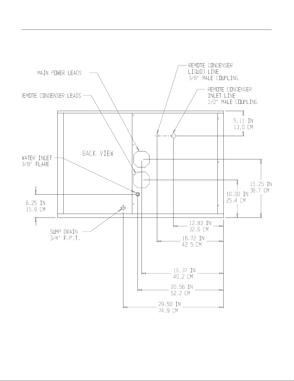
BACK VIEW OF CABINET
CME1202R & CME1402R
June 1996
Page 3
Page 4
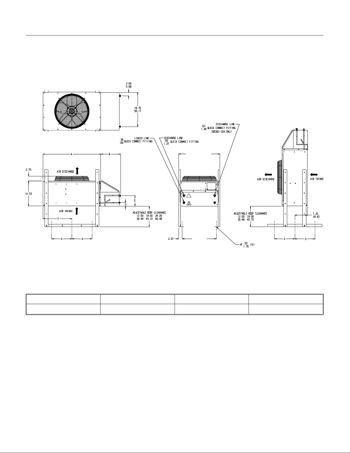
CME1202R & CME1402R
ERC401 SPECIFICATI ONS
23 13⁄16"
7
⁄8"
19
ERC Dimensions
ABFG
3
43
⁄8"10
3
⁄
"21
4
3
⁄
"16
4
5
⁄
"
8
June 1996
Page 4
Page 5
CME1202R & CME1402R
FOR THE INSTALLER: Locat ion & Assem bly
Location:
Afte r u ncrat in g and inspe ction , th e unit i s re ady fo r
installat ion . It is important that the machine be
installed in a location where it has enough space
around it to be accessible for service . Try to avoid
hot, dirty and crowded locations. Be sure that the
location for the mach ine is wit hin the
environmental limitations.
Storage Bin:
Tip th e sto rag e bin on its back , usin g par ts of the
carton to prot ect the exterior finish. Inst all th e leg s
packed with the BH90 0. If stacking use a heav y
duty leg kit (KLP6).
1. Arrange for prope r elec tric, water and drain. See
instructio ns for the plumbe r and for the electrician.
2. After mounting the legs pos itio n the ice s to rag e
bin in the sele cte d loc at ion :
Note: Allo w eno ugh sp ac e to th e lef t and back t o
service the machine. Do NOT push the bin into
position, inst ea d, lif t it there . Push ing a bin may
damage th e le g s and leg mo unts.
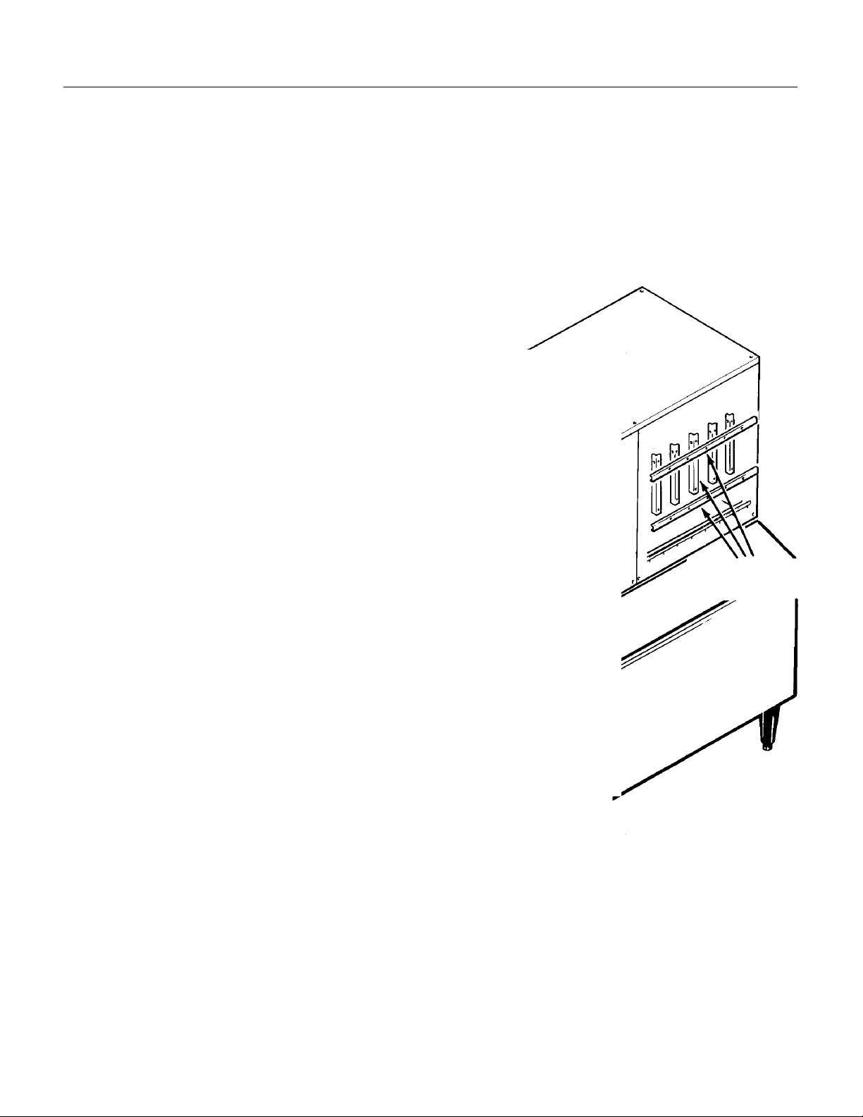
ICE MACHINE AND BIN ASSEMBLY
Level the bin in bo th the fron t to rear and side to
side directio ns by adjust ing the leg levelers .
3. Inspect the bin top mounting gasket. It must be
flat, with no gaps, to pro vide a good wat er se al
when the cuber is insta lled on top of the bin.
Ice Maker:
Install the mod ula r cube r on top of the bin using
care to be sure a good se al is made betwee n th e
two cabinets. Use of a mechanic al lift is
recommended . Alig n the hole s in t he bott om re ar
of the cabine t to mate wi t h the two mo untin g holes
on the top rear of the bin.
Use bolts and straps found on the back of the ice
machine to secu re th e ice mac hin e to the bin.
When alignme nt and levelin g are comp let ed,
tighten the bolts to secure the mounting straps.
Remove the front panel, and remove the
evaporator shipping brackets and hardwa re .
Remote Condenser:
A new condenser coil designed for the machine’s
capacity MUST be used. Because of the possibilit y
of mineral oil contamination, coils and line sets
that had been connect ed to R-12 , R-50 2 or R-22
units MAY NOT BE CONNECTED TO THIS
SYSTEM. Doing so voids the refrig era tio n syst em
warranty.
June 1996
SHIPPING
BRACKETS
Page 5
Page 6
CME1202R & CME1402R
FOR THE INSTALLER: Locat ion & Assem bly
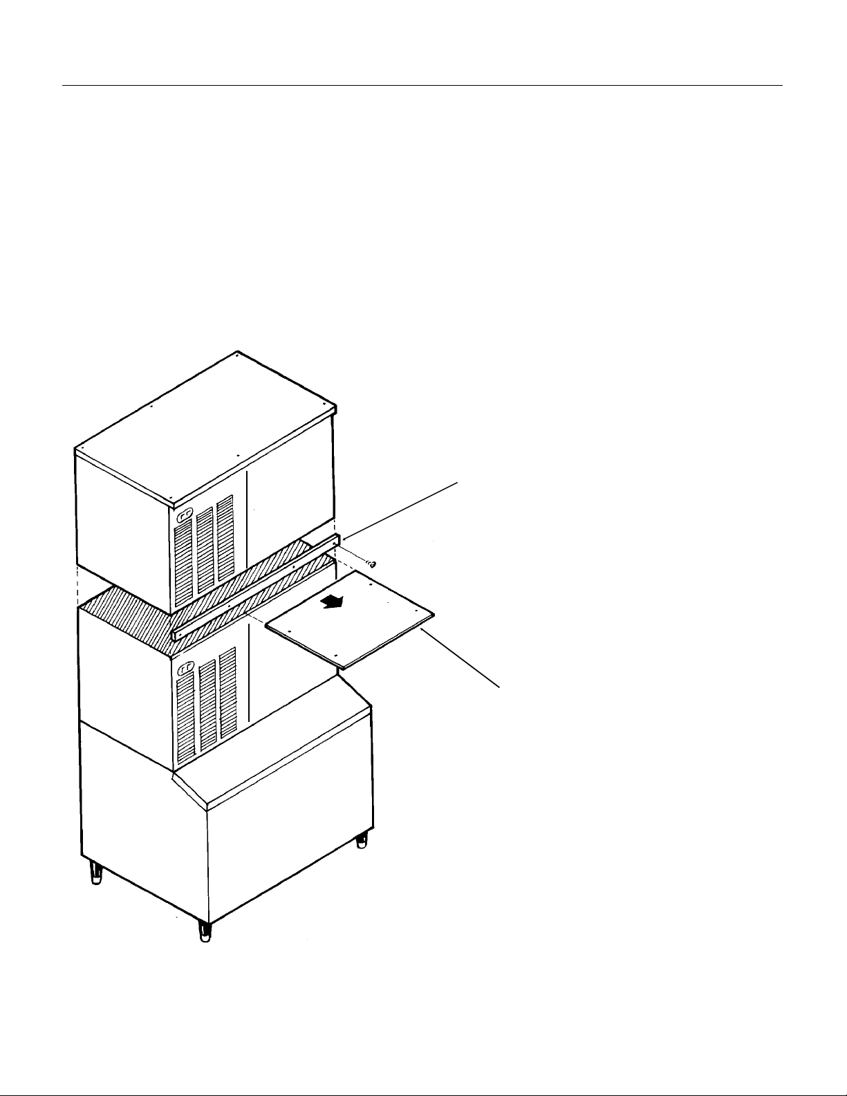
Stacking Instructions
A sta ckin g kit , KSCMS4 8, is require d to
interconne ct th e ice level co nt rols, seal the
freezing compartments, support the bin with heavy
duty legs, and retain the front panels.
Follow the installation instruc tions of the stackin g
kit, but in general:
Replace the orig ina l bin leg s wit h heav y duty leg s
(KLP6).
When stackin g two units, re move the top panel
and the evaporator cove r from th e lower ice make r.
STACKING
(The top removed from the lower ice make r will no
longer have any function.)
Add a strip of gasket (from the sta ckin g kit) to the
top edge of the bott om ice machines evap ora to r
compartment.
Install the pane l retainin g bra cke t onto the botto m
ice machine befo re pla cin g th e upper unit on it.
Place additio na l gask et ont o the top ed ges of th e
bottom ice machin e.
Carefully lift the uncra ted top unit onto the botto m
one and align the two cab ine ts. Use of a
mechanical lift is recommended for this step.
At the back of the two ice mak ers, bolt the upper
ice maker cabin et to the lowe r ic e maker cab ine t
using the moun tin g st rap s and bolt s fro m the
hardware package.
Add the relay kit to int erco nnec t th e two ice
machine’ s bin contro l circ uit s.
STAINLESS STEEL PANEL
RETAINING BRACKET
June 1996
Page 6
EVAPORATO R COV ER
Page 7
CME1202R & CME1402R
FOR THE INSTALLER: Scots man Remot e Condenser
Locate the condenser as near as possible to the
interior location of the ice maker.
Location of the condenser is limited by the specific
length of prec harge d ref rige ran t tu bin g supplied for
the application. The pre-charged tubing connects
the ice maker to the remot e co ndense r. The
condenser mus t be above the ice maker.
Select the be st av aila ble locat ion, protecting the
condenser from ext reme s of dirt , dust , and sun.
Meet all applicable bu ildin g codes.
Roof Attachment:
Install and atta ch th e remo te con dense r unit to the
roof of the build ing , us ing the meth ods and
practices of const ruct ion that co nform to the local
building code s, inc lud ing havin g a roofin g
contractor se cure the condense r to the roo f.
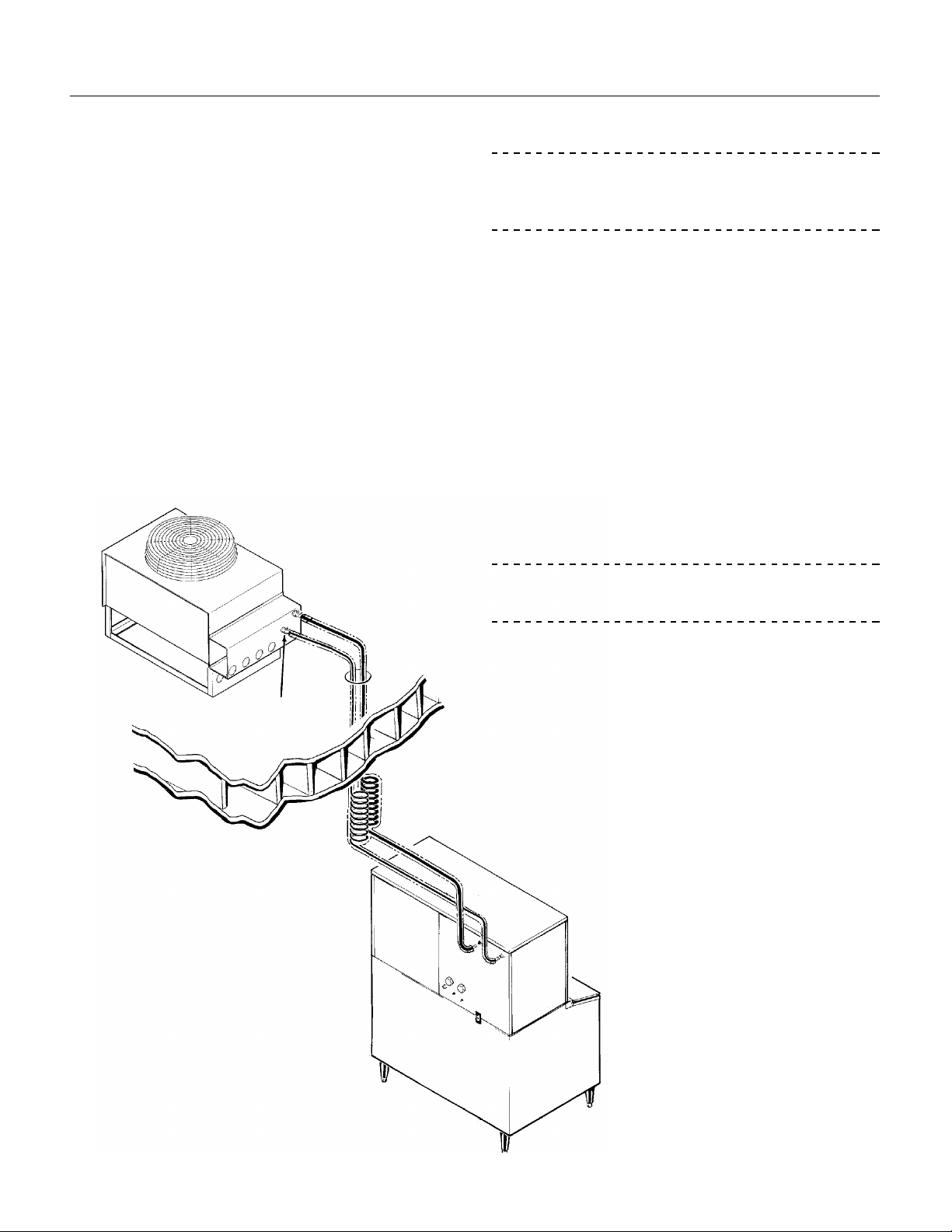
Precharged Line Routing
CAUTION
Do not connect prec harge d tubin g until all rou tin g
and forming of the tubin g is complet e. See the
coupling instructions for connecting instructions.
1. Each set of prech arg ed refrig era nt lines co nsis ts
of a 3/8 inch diameter liquid line, and a 1/2 inch
diameter discharge line. Both ends of each line
have quick connec t couplin gs , th e end withou t
access valves goes to the ic e make r.
Note: The openings in the buildin g ce iling or wall,
listed in the next step, are the minimum sizes
recommended for passin g the ref rige ran t line s
through .
2. Have the roofing contracto r cut a minimum hole
for the refrigerant lines of 1.75". Check local
codes, a separat e hole may be requ ired for the
electrical power to the condense r.
CAUTION
REFRIGERANT
CONNECTIONS
LOCATE CONDENSER
NO LOWER THAN ICE
MACHINE
DO NOT KINK OR CRIMP REFRI GE RANT
TUBING WHEN INSTA LLING IT.
3. Route the refrige rant lines throu gh the roof
opening.
Follow straight line routing whenever possible.
Any excess tubing MUST be reta ine d with in the
building.
4. Spiral any excess length of pre charge d tu bin g
inside the building. Use a horizontal spiral to
avoid any tra ps in the lines.
Note: Spiral nee d not be as
tight as illustrated.
5. Have the roofing contractor
seal the holes in th e roof pe r
local cod es .
TYPICAL
INSTALL AT ION
June 1996
Page 7
Page 8
CME1202R & CME1402R
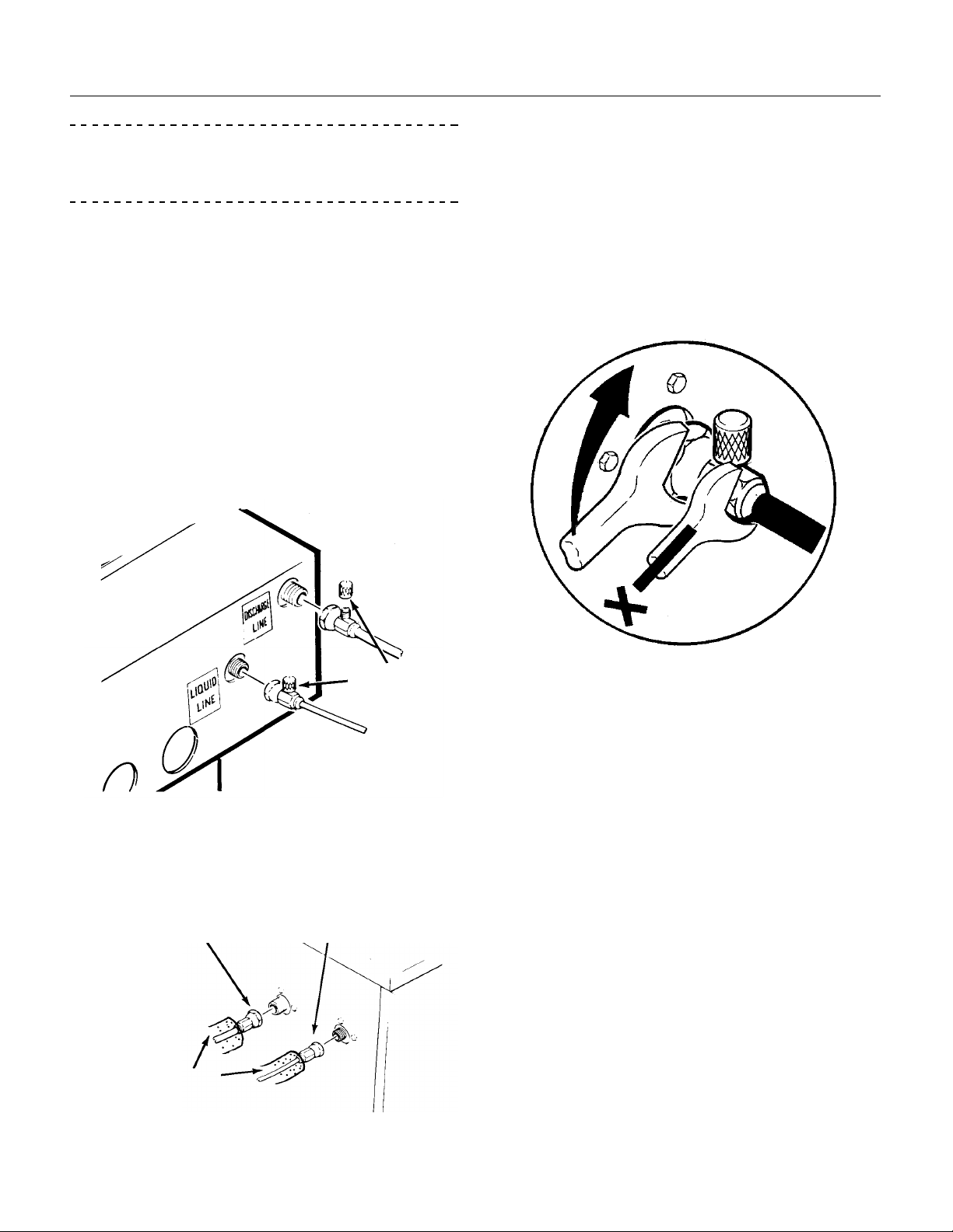
FOR THE INSTALLER: Coupling Ins truc tions
CAUTION
The couplin gs on the set s of pre ch arg ed lines are
self sealing when inst alle d pro pe rl y. Carefully
follow the instructions:
Initial Connec tions :
1. Remove the protector caps and plugs. Wipe the
seats and threaded surfaces with a clean cloth to
be certain that no fore ign matt er remains on them.
2. Lubricate the inside of the cou plin gs, especia l ly
the O-Rings with refrige rant oil.
••The 1/2 inch discharge line (schrader valve
end) goes to the remote condense r fitt ing
marked “discharge line”.
••The 3/8 inch liquid line (sch rad er valv e end)
goes to the remote con dense r fitt ing marke d
“liquid line”.
Final Connections :
3. Begin tighte ning the coup ling s tog et her by
hand, then using two wrench es (it is importa nt that
ONLY the nut on the precharged lines be turned,
the other parts of the coupling s must NO T be
allowed to turn or the proce ss will tear out the
diaphragms and they will be loose in the
refrigeration system) tighten the coupling until it
bottoms out or a definite increase in resistance is
felt.
TIGHTENING THE QUICK CONNECTS
SCHRADER
VALVES
••The 1/2 inch discharge line goes to the ice
maker fittin g mark ed “disch arg e line”.
••The 3/8 inch liquid line goes to the ice make r
fitting marked “liquid line.”
LIQUID LINEDISCHARGE LINE
INSULATION
4. Using a marker or pen, mark a line lengthwise
from the couplin g union nut to the bulkhea d. Then
tighten th e co up ling and ad dit ional 1/4 turn . As the
nut turns, the line will show when 1/4 turn is made.
5. After all connectio ns are ma de, and aft er t he
king valve has been open ed, ch eck the coupling s
for leaks.
June 1996
Page 8
Page 9
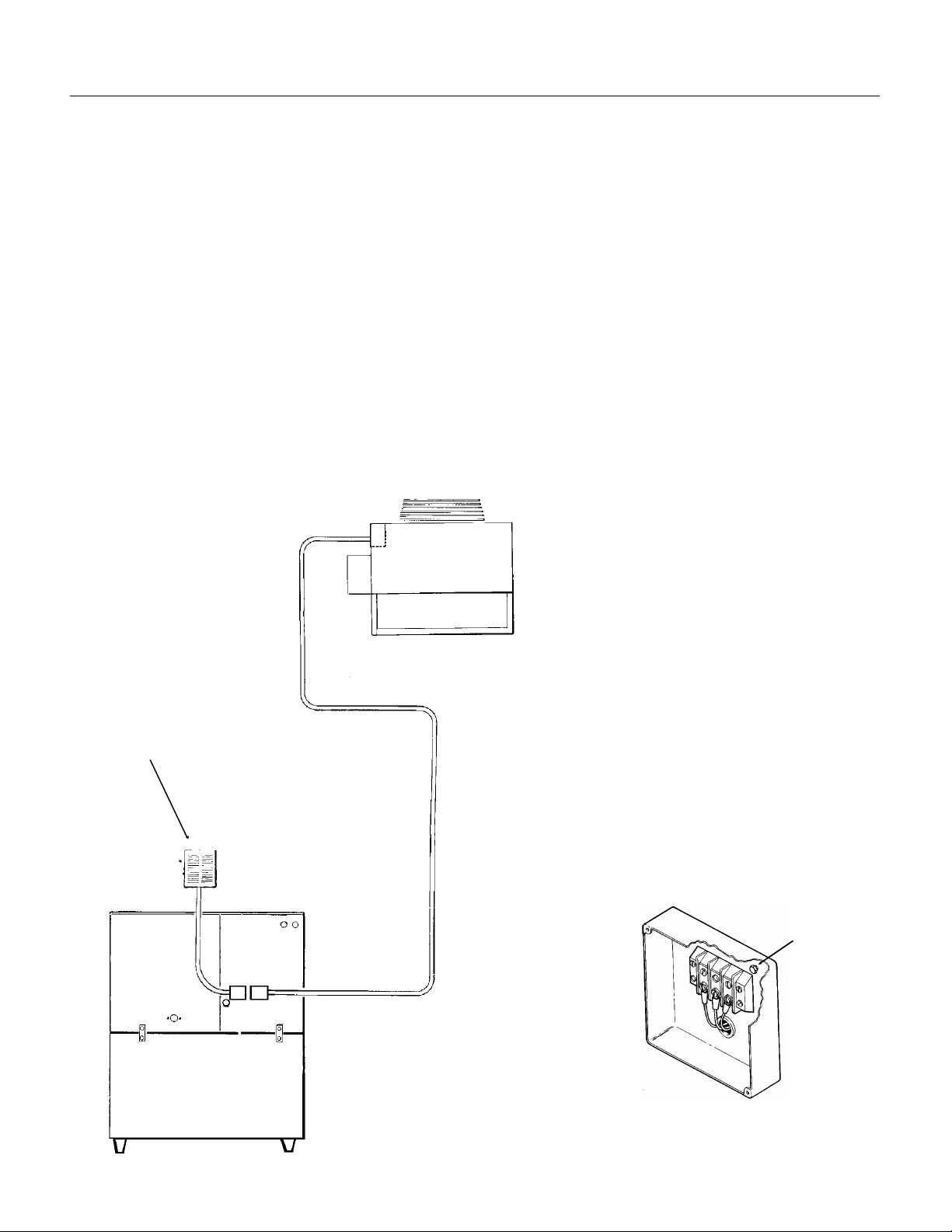
FOR THE ELECTRICIAN
DETAIL OF JUNCTION BOX, 3 PHASE SHOWN
CME1202R & CME1402R
See the ice machine namep lat e fo r curre nt
requirements to determine wire and fuse size to be
used for electrical hookup. When the cuber and
the remote conde nse r are co nnect ed , each must
be grounded to the other usin g the gro un d screw s
provided in the respe ct ive ju nction bo xes . The
cuber then requires a solid chassis to chassis
earth ground wire. See Wiring Diagram.
Be certain the cuber is connected to its own
electrical circuit and individ ually fus ed. Voltage
variation should no t exceed ten perce nt of the
nameplate rat ing , even under sta rtin g cond itio ns.
Low voltages can cause erratic ope rat ion and may
be responsible for seriou s dama ge to the ice
maker.
FOLLOW ALL APP LICABLE CO DES
ELECTRICAL CONNECTIONS
The Scotsma n remote con dense r is designe d to
be powered from the ice machin e. The re is a
separate electrical junctio n box at the back of the
ice maker for the remot e conden ser. Wire the
remote condense r to the ice maker in ac cord ance
with local and natio na l elect ric co de s. All ou tdoo r
wiring must be in rain proo f condu it.
Note: If connecting to another UL listed remote
condenser, follow the instuctions provided with that
product for electrical connect ions.
The condenser fan motor will run whenever the
compressor is running.
Electrical conn ection s are made at the rear of the
ice maker, inside the junction box.
All external wiring should conform to the national,
state and local electrical cod e require ments.
Usually an electrical permit and services of a
licensed electrician will be required .
HAND
DISCONNECT
SWITCH
POWE R
SUPPLY
INTERCONNECTING
WIRES
GROUND
SCREW
REMOTE CONNECTIO N
June 1996
Page 9
Page 10
HAND
SHUT OFF
VALVE
CME1202R & CME1402R
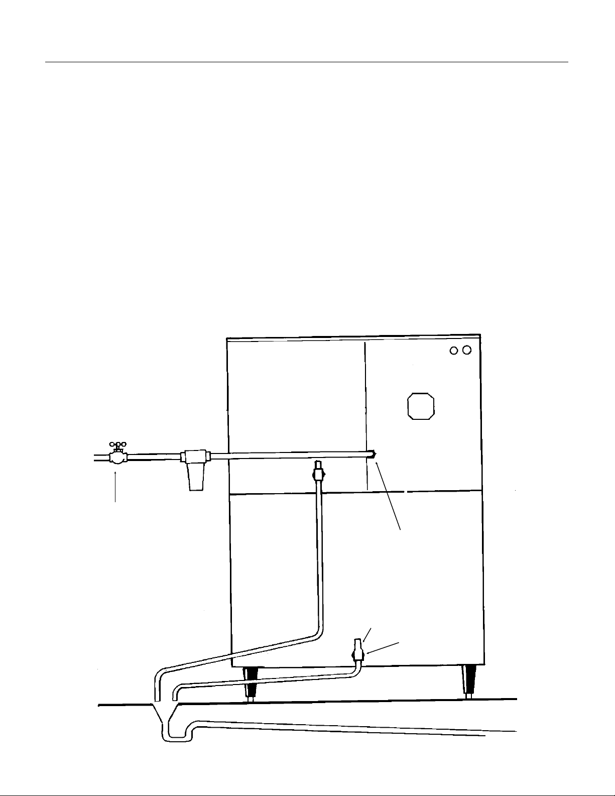
FOR THE PLUMBER
The recommended wat er supply line is a 3/8-inch
O.D. copper tubin g with a minimum opera tin g
pressure of 20 PSIG and a maximum of 80 PSIG.
Connect to cold wate r sup ply line with st anda rd
plumbing fit tin gs , with shut off valve insta lled in an
accessible plac e betwe en the wate r supply an d
the cuber. In some cases a plumber will be
required.
Water Limitations:
An ice machine is a food manuf act urin g pla nt , it
takes in a raw material, wate r, and turns it int o a
food product, ice. The purity of the water is very
important in obtaining pure ice and in maximizing
product life. It is generally bett er to filter the water,
although there is no one filter that will cure all
water prob lems. A good filt er co mbin ed with a
polyphosph at e fe eder gives about th e best overa l l
performance .
DRAIN
Connect ion s: A ll drain s are gravit y ty pe an d must
have a minimum of 1/4-inch fall per foot on
horizontal run s. The drain s to be insta lled to
conform with the local plu mbin g code. In stall a
vertical open ve nt on drain line high poin t to insure
good draining . The ideal drain receptac le is a
trapped and ven ted flo or dra in. Recommended bin
drain is 3/4 inch O.D. RIGI D tub ing and sho uld be
vented and run separately. Insulation for high
humidity areas is reco mmen ded.
The ice machine sump drain is 3/4" FPT. There
mus t be a ve nt at th i s con nect io n fo r p roper su m p
draining. Reco mmen ded dra in is 3/4 inch O.D.
RIGI D tu b in g and sh ou l d be run sep a ratel y.
Insulation for high humidity areas is
recommended .
POTABLE
WATER
SUPPLY
AIR GAP BETWEEN
DRAIN LINES AND
BUILDING DRAIN
SUMP DRAIN MUST
BE VENTED
3/4" FPT
OPTIONAL
FIL T ER
3/8" MALE FLARE
VENT
BIN
DRAIN
WATER SUPPLY AND DRAIN CONNECT ION
June 1996
Page 10
Page 11

FINAL CHECK LIST
OPTIONAL
FILTER
1. Is the cabinet in a roo m where ambie nt
temperatures are within the minimum and
maximum temperat ures spe cifie d?
2. Is there clearance at the left and back sides of
the cabinet for serv ice ac ces s?
3. Has water supply pressure bee n checke d to
insure a minimum of 20 PSIG and a maximum of
80 PSIG opera tin g pre ssure?
4. Is the cabinet level?
5. Check that any ship ping material has been
removed from inside the
cabinet.
6. Check that the reservoir is
properly secured to the bottom
of the evaporator plates.
7. Have all electrica l, wat er an d
drain conn ect ions been
properly made?
CME1202R & CME1402R
FINAL INSTAL L AT ION
8. Is the water supply line shut
off valve inst alle d and elect rical
wiring properly connected?
9. Check all refrigerant lines
and conduit lines, to guard
against vibration or rubbing and
possible failure .
10. Have the bin and cabinet
been wiped clean?
1 1 . Has the Manuf actu rers
Registration form been properly
filled out? Check for correct
model and serial numbers from
Serial nameplate, then mail to
the SCOTSMAN fac tor y.
12. Has the owner/u ser been
given the Service Manual and
instructe d how to op era te and
maintain the ice maker?
13. Has the owne r bee n given
the na m e and teleph on e
number of the authorized
SCOTSMAN Service Agency
serving him?
PRECHARGED
LINES
CONNECTED
LEVEL
ASSEMBLY
SUMP DRAIN
HAND SHUT
OFF VALVE
BIN DRAIN
June 1996
Page 11
Page 12

TIMER
CME1202R & CME1402R
INITIAL STA RT UP
Before Start Up:
1. Check that both the ICE-OFF-WASH rocker
switch and the COMPRESSOR ON-OFF toggle
switch are in the OFF position.
2. Switch on the electrical power. Electrical power
must be supplied to the ice machin e for 4 hour s
before start ing the compresso r for th e first time .
The crankcase heater will now heat the
compressor’s oil. The oil is warmed to evaporate
any refrige ran t that may hav e colle ct ed in it. If
there is refrigerant in the oil when the compressor
starts, the oil will foam and will not lubrica te the
compressor properly, shortening its life.
Do NOT start the compressor for the first time
unless the dome of the compressor is warm.
Start Up
1. Remove front panels by removin g scre ws at the
base and pulling out.
2. Remove two screws and the cont rol box cove r.
3. OPEN the water supply line shut off valve.
FRONT VIEW OF T IME R
ACTUATOR
BUTTON
CAM
FREEZE
PORTION
MICROSWI TCH
HARVEST
PORTI ON
4. Open the “king” valve on the receiv er.
5. Inside the control box is the shaft of the timer
and switch assembly. Rotate the shaft of the timer
clockwise until the ac tuator arm on t he microswitch
drops off outer cam int o cam slo t. See “Front Vie w
of Timer”.
6. Move the ICE-OFF-WASH to the ICE position.
7. Check the water fill cycle: For several minutes
the inlet water valve will be open and water will
flow into the reservoir. Near the end of the fill cycle
water should be drain ing thru the reserv oir dra in. If
at the end of the fill cycle the reservoir is not full,
rep ea t step 5.
Check that the sump covers are snapped in place.
Check that the wate r dist ribu to rs are pro per ly
seated at the top of the evaporators and that water
is flowing over all cube cells.
Note: Some water spray from the evaporators is
normal when the machine is new . The spray will
quit after a few cycles.
CONTROL BOX
CUBE SIZE
CONTROL
8. When the sump has filled, move the co mpre sso r
ON-OFF toggle switch, to the ON position.
ICE/OFF/WASH
BIN ICE LEVEL SWITC H
June 1996
Page 12
Page 13

INITIAL STA RT UP
CAMS
ADJUSTMENT
OF THE TIMER
9. Check operation of the freez ing cycle: Ice will
begin to form from the top of the evaporators
down. After t he first cycle, freezing time will ran ge
between 12 and 15 minutes. Longer time for
temperatures above 70
required whe n temperatures are below 70
Average co mple te cycle time is about 14 minutes.
10. After a n ice harvest, check Cube Size.
o
F. and shorter time
o
F.
CME1202R & CME1402R
CUBE SIZE DIAGRAM
JUST RIGHT
There is just enoug h water av ailable in the
reservoi r to ma ke one fu ll sized batch of cubes . A s
the water level drops, the water pump may pick up
some air at the end of the freezin g cyc le so so me
bubbles in the pump discharge hose at the end of
freeze is normal. If the water pump runs out of
water before th e end of free ze , th e cube size
control may be set too cold, or the water syst em
may be leaking water.
Compare cube size to the "Cube Size Diagra m "
To adjust the cube size, loca te cube size control in
the front of the cont rol box, and rot at e the
adjustment screw on e eight h of a turn:
••COUNTER Clockwise for SMALLER ice cubes
••Clockwise for LARGER ice cubes
Observe size of the ice in the next ice cube
harvest and repeat adjustme nt until correc t ice
cube is achieved.
11. Check Harvest Time. There must be eno ug h
time in harvest to defro st all the cubes bu t not an
excessive amount that will wast e capa city. The
length of the harvest cycle is determine d by the
timer cam positions.
If needed, adjust the harvest time so t here are
about 15 seconds of harve st time lef t afte r the last
cube has fallen from the evapora to rs.
Because harvest time varies with the wate r and air
temperat ure s at the ice mach ine , cold er air an d
water will result in faste r ice making but require
longer harvest cycles. Do NOT adjust harvest
time too short or the unit will not harvest all the
ice.
The harvest time is set by: loosening the set scre w
on the cam, ro tating the shaft to open or close the
distance bet wee n the hig h part of the cams, and re
tightening the set screw. More of an opening
between the cams hig h areas =more harv est time.
An adjust men t of the cube size may be needed
after the harvest time has be en changed, so check
the cube size again.
When the cubes are the correct size, they will be
connected toget her verti call y, and drop off in strips.
The batch weight wil l be about 13.5 to 14.5 lb.
Note: if the cubes at the bottom rows of some
evaporators are smaller than oth ers, the size di fferen ce
does not affect capacity or perf orman ce. However, the re
should be ice in all cells. If not, contact the Factory.
TOO SMALL
SET
SCREW
12. Check Bin Ice Level Control. When the unit is
in the harvest cyc le, place something solid against
the transducer so cke t (loca te d in the base to the
left of the evaporators). The machine will switc h off
at the END OF THE HARVEST CYCL E, and will
restart whe n the object is remov ed . The control
has a Full and a Partial positio n. At Full, the
machine will switch off when ice is 8" from the
transducer socke t. The control will not work on
bins taller than 8’. Note: Even when full the unit will
make a batch of ice if switched off and then on.
13. Replace all covers, panels and screws.
14. Fill out the Warra nty Reg istra tio n and
Customer Evalua tio n form. Ex plain to the user the
maintenanc e req uire men ts of the ice mach ine .
Info r m t he us e r o f the name an d te l ephone
number of the local SCO TSMA N Distribu to r or
service agency.
June 1996
Page 13
Page 14

RESERVOIR
CME1202R & CME1402R
FREEZING CYCLE OPERA TI ON
Water from th e sump ass embly is pumped to the
water distrib ut or syst em at the top of each
evaporator plate. From the water distributor the
water casca des by gra vity over all ce lls of the plate
and to the sump assembly be low.
At the beginning of t he freezing cycle, the electrical
circuit is complet ed to the compre sso r and the
water pump. The water pump operates
continu ously, through both the fre ez ing cycle an d
the harvest cyc le.
During the freez ing cycle, the hot gas solen oid
valve is CLOSE D and the wate r inlet solen oid
valve is CLOSED. When the ice cubes are partial ly
formed, the cube size control will sense the
temperature at whic h it is preset to CLOS E. This
will complete the electrical circuit to the timer. The
timer then controls th e remaind er of the free zin g
cycle. The timer will keep the ice make r opera tin g
in the freezing cycle fo r a sele cted length of time.
This will give the ice cubes time to fully form. after
that selected length of time, the timer will switch
the ice maker into the harve st cycle, through the
contacts of the timer assembly microswitch.
Low Temperature Freeze :
When the outside air te mpe rat ure is low, the Head
Pressure Reg ulato r will close of f the liqu id line to
the receiver, causing liqu id ref rige ran t to back up
into the condenser until th e head pressure builds
up to 240 PSIG. While this is occurring, the head
pressure regu lat or pa sse s disc ha rge gas int o the
receiver to keep the refrigerant flowing.
WATER DISTRIBUTION
INLET
WATER
VALVE
DRAIN
WATER SCHEMATIC
REFRIGERATION SCHEMATIC
June 1996
Page 14
Page 15

HARVEST CYCLE - HOT GAS BYPASS
RESERVOIR
CME1202R & CME1402R
When the timer switches the ice maker int o the
harvest cyc le, high press ure , hig h tempe rature gas
refrigeran t being disch arg ed from th e compre sso r
is diverted fro m the conde nse r thro ug h the hot ga s
solenoid valve into each evaporator plate. During
this cycle, the ref rige ran t bypa sse s the con dense r.
In the electrical circuit, both the compressor and
the water pump are operating and the hot gas
solenoid valve is energized and OPEN and the
water inlet so len oid valve is OPEN.
The finished ice cube s are rele ased from the side s
of each evaporator plate by the warming eff ec t of
the hot gas condensing in each evaporator plate
and the water casca ding over the ice cu bes. The
released ice cub es dro p int o the ice stora ge bin
below . At the end of the harvest cycle , the time r
cam will push the actuator arm to the microswitch
IN. If the ice level control is s till CLO SED, a whole
new cycle will begin. If the ice level control is
OPEN, the ice maker will begin to shut OFF.
Pump Down Cycle:
When the ice level contro l is open at the end of the
harvest cycle, power is removed fro m the liquid
line valve coil, and the pump down cycle begins.
The compressor will continu e to run until the pump
down control, sensing low side pre ssu re, opens at
15 PSIG.
WATER
DISTRIBUTION
INLET
WATER
VALVE
DRAIN
WATER SCHEMATIC
REFRIGERATION SCHEM ATI C
June 1996
Page 15
Page 16

CME1202R & CME1402R
COMPONENT DES CRIP TIO N
Cube Size Control
This reverse acting thermos ta t contro ls the length
of the freezing cycle. It is sensing the temperature
of the suction line. Whe n the suction line gets cold
enough, the cu be size con tro l closes (on
temperature fa ll) and starts the timer. A ch ange in
either ambient air or incoming water temperature
will affe ct the efficiency of the refriger ation system,
and this will vary the length of time it takes the
evaporator to reach the temperat ure at which the
cube size control is prese t to close . See CUBE
SIZE ADJUSTMENT BE FORE at tempt ing to adju st
the control.
Relay
The multi-function, three pole, double throw,
plug-in relay is insta lled direct ly int o a recept acle
on the printed circuit board in th e control b ox. The
relay funct ion s in pa rt to by-pa ss th e bin
thermost at cont rol to prev ent th e ice maker from
shutting OFF, when the bin thermostat opens
during the freezing cycle. The bypass action
serves to ensure full-s ized ice cubes with each
harvest cycle.
Timer - Ti me r & Swi tch As se mbly
The function of the time r beg ins whe n activa te d by
the cube size contro l. The outer su rfa ce , or la rge
diameter lobe of the timer cam, dete rmine s the
timer cycle for fin ish fre ez ing of the ice cube s,
while the inner surface , or sma ll diame ter lobe ,
determines the time cycle for the harvest cycle .
When the microswitch button is pushed in there is
power connected to the coil of the rela y, and the
unit is in the freeze cycle. When the microswit ch
button is released, the power to the relay is
stopped, and the unit goes into harvest. The
microswitch is actuated by a cam assembly
directly co nnected to the timer motor.
One complete rotation of the cam will take eight
minutes. Harvest is preset at three and one half
minutes, but is adjustable.
High Pressure Safe ty Control
This is a manual reset contro l that sh uts down the
ice maker, should the discharge pressure ever
reach 450 PSIG. Locate d below the co ntrol bo x.
Low Pressure Control (Pump Down)
CONTROL BOX
This pressure cont rol conn ects po wer to the
compresso r cont acto r coil. It s Cut In is 35 PSIG
and its Cut Out is 15 PSIG. Locate d below the
control box.
CUBE
SIZE
CONTROL
RELAY
TIMER &
SWITCH
June 1996
Hi Pressure
Reset, Push
to Reset
Page 16
Page 17

COMPONENT DES CRIP TIO N
Bin Level Control
CME1202R & CME1402R
This electronic control uses sound waves to
measure th e distan ce betwee n th e bott om of the
ice machine and th e top of the ic e in the bin . It is
designed to cont rol th e machine’s ice production to
maintain that distan ce.
The contro l is adjusta ble so that th e ice machin e
will maintain a certain height of ice. When set at
FULL it will not allow the machin e to fill the bin any
closer to the ice machine than about 8", and it will
not work if the distance to the bottom of the bin is
greater than 8 feet.
BIN ICE LEVEL
SELECTO R
SWITC H
ICE/OFF /WASH SWIT CH
Because it uses sou nd waves , a sligh t “ticking”
sound can be heard comin g from t he botto m of the
machine.
There are thre e parts to th e con t rol, the
transducer, the circuit board, and the ice level
control switch.
THE USER CAN SELECT THE
AMOUNT OF ICE TO BE
MAINTAINED IN THE BIN.
SOUND WAVES
June 1996
Page 17
FULL
PARTIAL
Page 18

WATER
DISTRIBUTO RS
CME1202R & CME1402R
COMPONENT DES CRIP TIO N
Water Inlet Solenoid Valve
The water inlet soleno id valv e fills the sump
assembly with water and exce ss wat er overflo w s
out the standp ipe and down the drain . Th is act ion
fills and rinses the sump during each harvest
cycle. The flow rat e is 1 g.p.m.
Water Distribution System
The water distribu tio n syst em ev enly sup plie s
water to all cells of the evapo rat or p lat es. The
water pump pumps water f rom the sump up the
vertical tygon tube to the tee. From the r e water is
channeled through the water manifold to the water
distributors, above each evaporator plate, and
from six holes with in each dis trib ut or, water flows
to the cells of each side of the evap ora to r plat es.
Gravity flow ret urn s th e unfro zen excess po rtio n of
water to the sump reserv oir fo r recircu lat ion .
Hot Gas Solenoid Valve
The hot gas solenoid valve functions only during
the harvest cyc le, to dive rt the hot discharge gas
from the compressor, by passing the condenser,
for direct flow in the evaporator plates to release
ice cubes fro m the ice cub e molds. The hot gas
solenoid valve is installed in a branch of the
discharge line. When the harvest cycle begins the
energize d soleno id co il lif ts th e valve stem within
the valve body, to cause the hot disch arg e gas to
be diverted to the evaporators.
SUMP STAND PIPE
OPTIONAL
WATER FILTE R
HAND
VALVE
PUMP
COMPONENT LOCATION
SUMP
DRAIN CAP
June 1996
Page 18
Page 19

CME1202R & CME1402R
CLEANING
A Scotsman Ice Syst em rep rese nt s a siza ble inves tme nt of time and money in any compa ny ’s bus ine ss. In
order to receive th e best retu rn for tha t inve st men t, it MUST receiv e period ic maintenance.
Maintenance and Cleaning should be scheduled at a minimum of twi ce per year.
CLEANING: ICE MAKER
1. Remove screws and the front panel.
2. Switch the compressor swit ch to OFF. Switch
the ICE-OFF-WASH rocke r switch to OFF.
3. Remove the control box cover, and rotate the
shaft of the timer and switch assembly
CLOCKWISE advanc ing to the freezin g cyc le.
(Beginning of the high er par t of the cam ag ain st
the microswitch).
4. Open the ice stora ge bin do or and dis card all
the ice.
5. Remove the hose cla mp, rubber cap and drain
all the water from the sump assembly into the bin.
Replace the rubber cap and hose clamp.
6. Mix 24 ounces of Scotsman Ice Machine
Cleaner with 2 gallons of warm (95
water.
7. Pour the clea nin g solu tio n into th e reservoir until
full.
8. Move the master switch to the W ASH po sit ion.
9. Let th e unit operate for 30 minutes.
During the wash cycle, if the mac hine run s out of
solution , mix 2 more ga llon s of solution per step 6,
refill the sump and continue the wash cycle for th e
remainder of the 30 minute s.
Scotsman Ice Machine
Cleaner contains acids.
These compounds may
cause burns.
If swallowed, DO NOT
induce vomiting. Giv e
large amounts of wat er
or milk. Call Physician
immediately. In case of
external contact, flush
with water.
KEEP OUT OF THE
REACH OF CHILDREN.
0
F. - 1150F.)
10. Move the ICE-OFF-WASH switch to the OFF
(center) positio n.
11. Remove the cap and drain th e clea nin g
solution from th e sump. Rep lac e th e drain cap .
12. Rotate the shaft of the timer and switch
assembly CLO CKWIS E to the harv est pos itio n
(low part of the cam against microswitch). Move
the ICE-OFF-WAS H switch to the ICE position to
start the Harvest cycle.
If after completing this proce dure one or more
evaporator plates does not have a full flow of water
for each vertica l column of cube s, sh ut down the
operation and remo ve and clean all wate r
distributor manifolds. Reinstall the water distributor
manifolds.
Note: The ice making portion of the water system
should b e sanitized after cleaning by repeating
steps 2-12 and substitutin g a sanitizing solution for
the cleaning solution.
13. Move the compressor swit ch to the ON
position to start th e ice making proc ess .
CAUTION
DO NOT use ice produced from the cleani ng
solution. Be sure none remains in the bin.
14. Check the next ice cub e harves t to be certain
that the ice cubes are clear and the acid taste is
gone.
15. Add hot wat er to th e bin to melt t he ice.
16. Replace all pane ls.
June 1996
Page 19
Page 20

CME1202R & CME1402R
CLEANING
Remote Condenser
1. Shut off th e ice machine.
The fa n b lade can
cause personal injury.
Disconnect power
before beginning to
clea n con de ns e r.
2. Remove dirt and debris that migh t be under the
condenser.
3. Brush off the botto m of the co nden ser fin s. Do
not use a wire brush.
4. Check to see that the inside of the co nden ser is
clean; light sho uld be visible th rou gh the fins . If
not, clean the int ern al pa rts by vacuum, pressure
washer and/or coil cleaner.
Ice Storage Bin
The interior liner of the bin is in contac t with a food
grade prod uc t: ice. The sto rag e bin must be
cleaned regularly to maintain a sanitary
environme nt . Once a wee k clea ning of the door &
frame with soap and wat er, a hot water rinse and
and air dry is a basic procedure. Scale that may
form on the plastic liner of a bin may be removed
by scrubbing the surface of the line with a mixture
of Scotsman Ic e Mach ine Clean er and hot wat er.
Remove any scale prior to sanitizing .
Inlet Water Valve
The inlet side of th e water valve has a screen in it
to protect the int ern al comp on ents from debris th at
may be carried to the valve by the water. If the
screen becomes clogged, it must be cleaned off.
1. Shu t off the wate r supply .
2. Unplug electrical connector from the valve .
3. Dismount valve from cabinet.
4. Remove inlet connect ion from valv e.
5. Brush debris from
sceen.
6. Reverse st eps 1-4 to
reassemble .
To remove scale:
1. Mix a c lea ning solution of 4 ounces of Sc otsma n
Ice Machine Cleaner to 4 pints of hot (9 5
0
11 0
F.) water.
Scotsman Ice Machine
Cleaner contains acids.
These compounds may
cause burns.
If swallowed, DO NOT
induce vomiting. Give
large amounts of water
or milk. Call Physician
immediately. In case of
extern al contact, flush
with water.
KEEP OUT OF THE
REACH OF CHILDREN.
2. Remove all ice from the bin.
3. Using rubber gloves, dip a nylon sc ouring pad
into the cleaning solut ion , an d scrub th e scale off
of the liner.
4. After the scale has been removed, rinse all of
the surfaces inside the bin with clean, potab le
water.
To sanitize the bin and ice machine:
Follow local codes for f reque ncy of sanitizing . Use
an approved sanitizer and follow the directions and
warnings of that sanitiz er or use the follo wing
instructio ns for use of hous ehold blea ch, if it meet s
local cod es :
1. Remove all ice from the bin.
2. Mix a sanitizing solution of 1 ou nce of
household bleach to 2 gallons of water.
3. Using clean rubber glov es and a clean cloth,
wipe all interior surfa ces of the ice machin e and
ice storage bin with the sanitizing solution.
Immerse any small part s in the sanitizin g so lut ion
and wash the parts, flus hin g the solu tio n
thoroughly in, over and thro ugh all parts and
surfaces of the parts being clea ned.
0
F. to
SCREEN
4. Allow to air dr y.
INLET
WATER
VALVE
June 1996
Page 20
Page 21

CME1202R & CME1402R
SYSTEM SPECIFICATIONS: CME1202
The following numb ers are a guide line to field op era tio n There will b e some varia tion from unit to unit.
The numbers headin g the colu mns are: Cond enser air te mp. /Ca bin et air temp ./ Water temp.
0/70/55 90/90/70 110/90/80
Typical Cycle Time 16 - 17 minutes 17 - 18 minutes 19 - 20 minutes
Standard Harvest Time*
1
3
⁄2 minutes 3 1⁄2 minutes 3 1⁄2 minutes
Typical Freeze Cycle
Suction Pressu re, End of
Cycle
Typical Freeze Cycle
Discharge Pressure,
End of Cycle
Typical Harvest Cycle
Suction Pressu re, Peak
Typical Air Cooled
Harvest Cycle Discharge
Pressure, Min
* See page 13 for harvest time optimiza tio n ins tru ctio ns .
Typical Harvest Ice Wei g ht
36 PSIG 35 PSIG 39 PSIG
250 PSIG 260 PSIG 305 PSIG
78 PSIG 100 PSIG 125 PSIG
140 PSIG 185 -190 PSIG 225 PSIG
••13.5 t o 14 .5 lb.
Refrigerant Char ge:
••336 ounces of R-404A when connected to a MAC 7G condenser
••448 ounces of R-404A whe n co nnect ed to a RCE1401 co nd enser
••448 ounces of R-404 A when co nn ect ed to a ERC401 conde nse r.
Typical Compressor Amp Dra w
Single phase
••5 minute s int o fre eze: 14 - 15 Harvest: 17 - 18
Three phase
••5 minutes into freeze : 8 - 9 Harvest: 10 - 10.8
High Pressure Cut Out
••High pressure saf et y, Man ua l rese t, cut out at 450 PSI G
Ice Level Control
••Maximum Range = 8 feet
••Partial Fill Setting: = 21" - 22" from the base of the ice machin e
Time r
••1 revolution takes 10 minute s (cha nged from 8 in June 1996)
Cube Size Control
••Cut In adjustable between 0
o
F. an d +250F.
June 1996
Page 21
Page 22

CME1202R & CME1402R
SYSTEM SPECIFICATIONS: CME1402
The following numbers are a guideline to fie ld opera tio n. There will be some variat ion from unit t o unit.
The numbers headin g the colu mns are: Cond enser air te mp. /Ca bin et air temp ./ Water temp.
0/70/55 90/90/70 110/90/80
Typical Cycle Time 15 - 17 minutes 16 - 17 minutes 18 - 19 minutes
Standard Harvest Time*
1
3
⁄2 minutes 3 1⁄2 minutes 3 1⁄2 minutes
Typical Freeze Cycle
Suction Pressu re, End of
Cycle
Typical Freeze Cycle
Discharge Pressure,
End of Cycle
Typical Harvest Cycle
Suction Pressu re, Peak
Typical Air Cooled
Harvest Cycle Discharge
Pressure, Min
* See page 13 for harvest time optimiza tio n ins tru ctio ns .
Typical Harvest Ice Wei g ht
35 PSIG 31-35 PSIG 36 PSIG
265 PSIG 270 PSIG 310 PSIG
80 PSIG 90-95 PSIG 110 PSIG
155 PSIG 180- 200 PSIG 235 PSIG
••13.5 t o 14 .5 lb.
Refrigerant Char ge:
•• 336 ounc es of R-404A when connected to a MAC 7G condenser
•• 448 ounces of R-404A whe n co nnect ed to a RCE140 1 cond enser
••448 ounces of R-404 A when co nn ect ed to a ERC401 conde nse r.
Typical Compressor Amp Dra w
Single phase
••5 minute s int o fre eze: 15 - 16 Harvest: 22 - 23
Three phase
••5 minutes into freeze : 9 - 10 Harvest: 13 - 14
High Pressure Cut Out
••High pressure saf et y, Man ua l rese t, cut out at 450 PSI G
Ice Level Control
••Maximum Range = 8 feet
••Partial Fill Setting = 21" - 22" from the base of the ice machine
Time r
••1 revolution takes 10 minute s (cha nged from 8 in June 1996)
Cube Size Control
••Cut In adjustable between 0
o
F. an d +250F.
June 1996
Page 22
Page 23

ADJUSTMENTS
CLOSE UP
VIEW OF TIMER
SWITCH
ACTUATOR
Electrical power
present in the control
box can cau se perso na l
injury.
Disconnect power
before beginning to
adjust timer.
Adjustment Of The Timer & Switch Assembl y
One complete revolu tio n of the cam on the timer
takes eight minu tes. The harves t time set at the
factory is three and a half minutes.
It. is importa nt that th e lengt h of the harve st cycle
allow enough time for all th e ice cube s to fall fro m
the evaporator . Too short of a time will cause the
evaporato r to fre eze up and stop ejecting ice into
the bin. Too much time wastes ic e making
capacity, energy and wa te r. Adjustment of th e
harvest cycle may require a corresponding
adjustment of the cube size contro l. Rot at ing the
shaft of the timer cam clockwise will allow puttin g
the machine int o eit her t he free zing cycle or
harvest cycle, as required in the cleaning
instructions.
CME1202R & CME1402R
MICROSWITCH
CAM
To Adjust The Timer & Sw itc h Ass em bly :
The length of the harvest cycle can be changed by
loosening the set screw on the cam, and then
rotating the shaft so that the opening between the
cams change. More of an opening between the
cams = more harvest time . The harv est time may
be reduced if not needed. This will yield more ice
per day.
ADJUSTING TIMER
TIMER
CAM
June 1996
Page 23
Page 24

CME1202R & CME1402R
SERVICE DIAGNOS IS: Wat er
SYMPTOM POSSIBLE CAUSE PROBABLE FIX
No ice is made Inlet water valve will not open or
is dirty
No water being pump ed ove r
evapora to r s.
Water inlet valv e lea ks thru at
high rate
Cubes are not uniform in shape Water distribu to rs are dirty Clean water system
Long Freeze Cycle Inlet water valve leaks through Replace inlet water valve
See electrical/ad jus tme nt See electrica l/a djustme nt
Makes thick ice/freezes up Water inlet valve restrict ed Clean or replace valve
Low water pressure Check water filter or supply
Sump covers out of positio n Re-positio n sump cov ers
Cubes too larg e Inlet wate r valve leak s thro ug h Replace inlet wat er va lve
See electrical/ad jus tme nt See electrica l/a djustme nt
Low Capacity Incoming water very warm Check water temperature to
Lack of water See unit runs out of water
Unit runs out of water Reservoir leaks Repair leak
Inlet water valve restricted Clean or replace valve
Short harvest cycle Adjust timer
Water pressure too low Check sup ply
Clean inlet screen , check coil,
replace va lve if req uire d
Check pump motor, replace
pump if motor will not run.
No water in reservoir, check inlet
water valve , che ck res ervo ir for
leak.
Replace inle t wat er va lve
building
June 1996
Page 24
Page 25

CME1202R & CME1402R
SERVICE DIAGNOS IS : Elect ric al and/or Adjus t ment s
SYMPTOM POSSIBLE CAUSE PROBABLE FIX
Machine does no t op era te No power Reconne ct powe r
High pressure control open Reset, check machine
High tempera tu re cut out open Hot gas valve leak s thru , replace
P. C. Board Op en Replace bo ard
Master switch open Test/replace
Timer contacts open Replace timer
Bin ice level control holding
mac hine off
Makes thick ice/freezes up Harvest Cycle too short Adjust timer for lon ger harv est
Low water pressure Check water filter or supply
Hot gas valve defect ive Replace hot ga s valv e
Sump covers out of positio n Re-positio n sump cov ers
Cubes too small Adjust cube size
Cube size contro l stuc k ope n Replace cu be size contro l
Runs, makes no ice Pump problem or water leak in
reservoir
Water inlet valv e eit her lets in no
water or leaks th rou gh
Timer stuck Replace timer
Relay does not energize; unit
stuck in harvest
Long freeze cyc le Water inlet valve leaks through Re pla ce inle t wat er va lve
Water tempe rat ure too high Advis e user
Cubes too smal l Cube size set wrong Adjust cube size
Cubes size contro l stu ck clos ed Repla ce cu be size contro l
Cubes too large Water inle t valv e lea ks throu gh Replace inle t wat er va lve an d
Compressor cycles on and off on
pump down contro l
Compressor will not run Low pressure con tro l will not close Check pump down control fo r
Unit cycles on and off anytime in
any cycle
Low refrigerant charge Locate leak, repair, replace drier,
Liquid line valve or drier restricte d Check and repla ce
TXV restricted Check and replace
Head pressure co nt rol valv e not
working (low condensing temp.)
Contactor coil op en Check/replace cont act or
Compressor wind ing s op en Check repla ce co mpre sso r
Loose con ne ct ion in PC boa rd Replace PC board
See page 27
cycle
Check water system and pump
Replace inle t wat er va lve
Replace rela y
adjust cube size control
evacuate and weigh in nameplate
charge.
Check/re place head pressure
control valve
proper operation
June 1996
Page 25
Page 26

CME1202R & CME1402R
SERVICE DIAGNOS IS: Refri geration and/or Mec hanic al
SYMPTOM POSSIBLE CAUSE PROBABLE FIX
Poor harvest Hot gas valve does not open Check for power to the coil, check
for not open ing , replace
Head pressure co nt rol valv e does
not maintain enou gh head
pressure.
Unit cycles off during freeze or
harvest
Low capacity High head pressu re, from dirt y
Unit shuts off befo re bin is full Bin Ice level co ntrol is set to
Compressor cycles on and off Low pressure control opening
Frost on compresso r Some frost will not hurt Do nothing
Hi temperature switch opens and
closes
condenser, fa ulty fan motor
Non condensabl e gas in the
system
Extreme ho t loca tio n Re loca te the cabinet
Overcharge of refrigerant Evacuate and weigh in nameplate
Hot gas valve leaks thru At the end of the freeze cycle
Liquid and discharge lines are in
contact with each other
“Partial ”
and closing
Compressor ov erh eats TXV not lettin g enough refrig era nt
TXV meters too much refrig erant Replace TXV
Replace he ad pres sure con tro l
valve.
Hot gas valve leak s thru , replace it
Clean condenser, rep air fa n
motor
Purge system, evacuate and
weigh in nameplate charge
charge
there should be frost on the
evaporator end of the hot gas
tubes, if not replace the hot gas
valve
Separate and insulate them
Move bin Ice level rocker switch
to “Full”.
Check low side pressure, liquid
line valve must open and low side
pressure raise ov er 35 PSIG
before pump down control will
close to run compressor
into evaporators, adjust or
replace TXV
Mechanical fault with
compresso r, rep lac e comp res sor
June 1996
Page 26
Page 27

CME1202R & CME1402R
SERVICE DIAGNOS IS: Bin Ice Level Control
CONDITION DETERMINE CAUSE PROBABLE CORRECTION
Ice Machine does not run, it
has power to it, the high
pressure c ontrol is closed,
the on/off switch is set to ON
(the compressor will n ot
operate until the liquid line
valve opens, but the pump
should be working if there is
no ice in th e bin).
Machine runs , make s ice,
switches on and off, but ice
level cannot be controlled.
Indicator light is out or
flickers, board may seem to
be off
A. Listen for a ticking sound from
transducer.
B. Remove front panel(s), twist
transducer 1/ 4 turn and pull out.
DO NOT UNPLUG with power
connected. Ex amine the
transducer, the inside must be
clean an d dr y.
C. Check powe r to bin level
control board.
D. Disconnect el ectri ca l power
and test ice machine circuit by
attaching a jumper wire between
bin thermostat posts on circuit
board part no. 12-1912-01 (the
circuit board with the timer on it).
Reconnect power.
E. Transducer or ice level board
assembly defectiv e.
Ice level switch may be defective.
On boards with a light, check by
moving switch & watching light.
Check connection to ice level swit ch Repair or replace harness to switch
If no noise, go to C. If there is a
noise, chec k for a ligh t on the board
(models built after 4/9 3). If there is a
light on, check relay contacts N.O.
and COM. The contacts should be
CLOS ED. If clo sed , go to D. If no t,
replace the board. If ligh t is off, or
prior model, go to B.
If the inside of the transducer (above
screen) was wet, replace it. Set bin
level to FULL and aim at an object
about 1-3 feet away. Machine
should restart, if not go to D.
Should be 12 volts from transformer,
if not replace transformer. If there is
power go to D.
If machine does not st art go back to
machine cir cuit. If machin e sta rt s ,
disconnec t electric al power, remove
jumper wire and reconnect electrical
power . The n go to E.
Replace tran sdu ce r. Se t bin level to
FULL and aim at an object about 1-3
feet away. Machine should restart. If
not , re place the board.
Replace ice level switch
PARTIAL
VIEW OF
CIRCUIT
BOARD
12-1912-01
TIMER
PLUG - IN
RELAY
BIN THERMOSTAT
June 1996
Page 27
Electrical S hock Hazard Can
Cause Personal Injury.
Disconnect Power Before
Servicing.
Bin Thermostat Posts at Line
V olt ag e.
POSTS MENTIONED IN
“B” ABOVE
Page 28

CME1202R & CME1402R
REMOVAL AND REP LACE ME NT
Cube Size Control
To remove the cube size con tro l:
Electrical Sh ock Hazard .
Electrical shock can
cause person al injury.
Disconnect power
before begin ning to
service compon ents.
Water Distr ibutor Tubes And Manifold Tubes
To remove the water dis trib ut or tube and manif old
tube:
1. Remove the front panel.
2. Slide the water distributor tube to th e front about
1/8-inch alon g the top of the evap ora to r plat e, unti l
the water distrib ut or tube can be unsnapp ed from
the flexible no tch and lifted upward.
WATER DISTRI BUT OR
1. Remove front panel.
2. Remove cover fro m cont rol box.
3. Trace ca pilla ry tube, from the cube size contro l
to the refrigerant suction line.
NOTCH IN BACK OF
CONTROL BOX
CUBE SIZE
CONTROL
REPLACEMENT OF THE CUBE SIZE CONTRO L
3. Unsnap and disconnect water distribut or tubes
from the wate r ma nif old section . To replace t he
water distrib ut or tu bes and manif old tubes , reve rse
the removal proce du re. BE SURE the notch es in
the water manifold tubes properly engage the
alignment keys in the tee . BE SURE the wat er
distribut or tube is secure ly faste ne d at the notch at
both sides of the evaporator plate. Check identical
attachment f or the left water distributor tube and
notch; also, that th e distributor/manifold
connections at the top center of each evaporator
plate is snug against the top of the plate.
4. Remove the coiled capilla ry tub e bulb from the
tube well on the suction line .
5. Remove electrical lea ds fro m the cube size
control.
6. Remove screws and pull the capilla ry tub e
through the notch in the back of the control box.
Remove the cube size co ntrol. To replace the cub e
size control, reverse the removal procedure.
June 1996
Page 28
Page 29

REMOVAL AND REP LACE ME NT
CME1202R & CME1402R
Inlet Water Solenoid Valve Assembly
To remove the inlet wat er so lenoid valve assembly:
Electrical Shock Hazard.
Electrical shock can
cause personal injury.
Disconnect power
before beginning to
service components.
Water Pump
1. Remove front panel.
2. Unplug water pump ele ct rical co nnect ion .
3. Drain water res ervo i r.
4. Use corbin clamp plie rs t o loose n and slide
corbin clamps on hoses away from pump.
5. Remove screws reta inin g pump to bracket .
6. Pull pump out of ice machine .
7. Reverse to reassemble.
8. Replace front panel.
1. Shut OFF water supp ly to machin e.
2. Loosen and remove outle t wat er line from the
inlet water so lenoid valve asse mbly.
3. Remove screws and pull the water so len oid
valve out to gain acce ss.
INLET WATER
VALVE
REMOV A L OF TH E
INLET WATER VAL VE
8. Reconne c t electrical power.
Transducer
1. Disconnect electrical power BEFORE removing
transducer.
2. Remove the fro nt panel an d loca te the
transducer so cke t.
3. Twist inner portio n of tra nsduc er
counter-clockwise and push up gently.
4. Unplug transducer an d remove from the
machine.
5. Reverse st eps 1-4 to reas semb le.
4. Pull electrical cord fro m solen oid coil termina ls.
5. Remove inlet wat er fit tin g fro m the wate r
solenoid valve. To replace the inlet water valve
assembl y, reverse the removal pro ced ure s.
Bin Ice Level Control Circuit Boar d
1. Disconnect Electrical Power before removing
circuit board.
2. Remove front panel.
3. Remove control box cover.
4. Remove wires from circuit board co nnect ions.
5. Unlock circuit board fa st eners by twistin g 1/2
turn.
6. Pull circuit board of of f faste ner pos ts.
7. Reverse to reassemble, refer to wiring diagram
as ne eded .
June 1996
Page 29
Page 30

CME1202R & CME1402R
REMOVAL AND REP LACE ME NT
Thermostatic Expansion Valve
1. Before replacing this valve, be cert ain that th e
valve is the cause of the pro ble m, and canno t be
adju sted.
2. Remove the front panel.
3. Discharge and reco ver th e refrigerant.
4. Locate the TXV bulb (on the suction line),
remove the clamps an d bulb from the tube.
5. With the refrige rat ion syste m open, unsweat the
TXV from the tubing.
6. Place the new TXV in positio n.
7. Wrap the new TXV body with heat sin k mat eria l.
Do not get any moisture in the valve .
8. Carefully braze the valve to the tubing. Examine
the joints , if they loo k go od proce ed to the ne xt
step, if no t, re -do the m.
9. Install a new drye r, and braze it in place also.
10. Reattach the TXV bulb to the suc tio n line in th e
same place as the old one.
1 1 . Eva cuat e the syst em to 300 mic ron s.
12. Weigh or measure the nameplate charge into
the receiver.
13. If the ma ch ine has been of f on the bre ake r
there may be refrig erant trapped in the oil of the
compresso r, so do not restart until the compre sso r
has been warmed by the crankcase heater for 4
hours. If the compresso r was warm th rou ghout th e
replaceme nt proce ss, the ice mach ine may be
restarted with out wait ing to re-warm the
compresso r.
Hot Gas or Liquid Line Valve.
1. Before replacing this valve, be cert ain that th e
valve is the cause of the pro ble m.
2. Remove the front panel.
3. Discharge and reco ver th e refrigerant.
4. Unplug the coil of th e valv e.
5. With the refrige rat ion syste m open, unsweat the
valve from the tubing .
6. Place the new valve in posit ion .
7. Wrap the new valve bo dy with heat sink
material. Do no t get any moist ure in the valve.
8. Carefully braze the valve to the tubing. Examine
the joints , if they loo k go od proce ed to the ne xt
step, if no t, re -do the m.
9. Install a new drye r, and braze it in place also.
10. Plug the power cord back onto the coil.
1 1 . Eva cuat e the syst em to 300 mic ron s.
12. Weigh or measure the nameplate charge into
the receiver.
13. If the ma ch ine has been of f on the bre ake r
there may be refrig erant trapped in the oil of the
compresso r, so do not restart until the compre sso r
has been warmed by the crankcase heater for 4
hours. If the compresso r was warm th rou ghout th e
replaceme nt proce ss, the ice mach ine may be
restarted with out wait ing to re-warm the
compresso r.
June 1996
Page 30
Page 31

V APOR VAPOR
TEMP. PRESS. TEMP. PRESS .
(DEG F) (PSIG) DEG F) (PSIG)
-20 17 70 146
-18 18 72 150
-16 20 74 155
-14 21 76 161
-12 23 78 166
-10 24 80 171
-8 26 82 177
-6 28 84 182
-4 29 86 188
-2 31 88 194
0 33 90 200
2 35 92 206
4 37 94 212
6 39 96 219
8 41 98 225
10 43 100 232
12 46 102 239
14 48 104 246
16 50 106 253
18 53 108 260
20 55 110 268
22 58 112 275
24 60 114 283
26 63 116 291
28 66 118 299
30 69 120 307
32 72 122 316
34 75 124 324
36 78 126 333
38 81 128 342
40 85 130 351
42 88 132 360
44 91 134 370
46 95 136 379
48 99 138 389
50 102 140 399
52 106 142 409
54 110 144 420
56 114 146 430
58 118 148 441
60 123 150 452
62 127 152 464
64 132 154 475
66 136 156 487
68 141 158 499
REFRIGERAT ION SERVICE
CME1202R & CME1402R
This ice mac hine uses R-404A refrigerant and polyoles ter oil. Do NOT
use mineral oil in this refrig era tio n syste m.
••R-404A is a "Near Azeotrop e" so liqu id cha rgin g is required: See the
nex t page .
••Whe n the system is serviced, a special liquid line drier is required . It is
included with replacement compressors.
••R-404A is not compa tib le with minera l oil, so these ice machin es use
Polyoles ter oil. Po lyole st er oil ab sorb s wat er very easily . When one of
these refrige ration systems is opened for service, it must be re-se ale d
as soon as possible (15 minutes maximum).
••Special leak detec tio n equipment is required to loc ate small ref rige ran t
leaks. Usua lly a leak detec to r capable of dete ct ing a Halon gena ted
refrigerant or HFC-134A will work. Check with the leak detector
manufacturer if in do ubt.
Access Valves: To use the access valves :
••Remove the cap from the stem, use a 3/16" allen wrench to check
that the valve is CLOSED. The remove the core ca p.
••Close the valve and repla ce the caps when the job is finis hed.
The valve must be closed and the ca ps mus t be on or the valve
will leak.
General Information:
Work on the refrig era tio n syst em shou ld only be done when it is certa in
that the system needs repair.
••Refrain from checking refrigera tion pre ss ures without reason.
Visual insp ect ion of the wat er sys te m, observation of the ice
formatio n, amp dra w, volt age, and other tech nique s will lead to proper
diagnosis.
••If gauges must be used, don’t always che ck the high side pressure. If
the condenser is clean and seems to be operating correctly, it most
likely is.
••If gauges must be used, use very short hoses to minimize ref rige ran t
discharged into the air.
••Refrigeran t sh ould no t be added except as a way to determine the
proper opera tion of the product . If the syst em was low on refrig era nt ,
there is a leak, and it must be found and repaired.
••This system has a critical charge, it must be recharged with the
correct amount of refrigera nt as listed on the nameplate of the ice
machine, or performance will suffer.
•• Anytime th e refrigeration system has been opened , the drye r sho uld
be replace d. Note: Only a HFC type dryer can be used.
••When brazing the tubing connections to components such as the
TXV, the component must be protecte d by heat sink mate rial.
Recover, reclaim or recycle refrige ran t. The me th od chosen is up to
the service comp an y. Any refrigerant placed into a Sc otsman ice machine
must meet ARI sp ec 7 00-93 . Rec laim pro grams are available throu gh
most refrige ran t who lesa lers .
June 1996
Page 31
Pressure-Temperature Ch art for R-404A
Page 32

Access Valves
Note: There are no valve
cores in this valve.
CME1202R & CME1402R
LIQUID CHARGING
Instructions for R-404A
In preparatio n for c hargin g, the low side hose
should have a sight glass, and/ or a rest rict or
device (such as a "Charge Fas ter ") insta lled in it
for metering liquid into the low side of the system.
1. Af ter a thoro ugh evacuat ion to at least 200
microns, shut off the manif old valves an d switch
off the vacuum pu mp.
2. Place a drum of R-40 4A onto an electroni c
scale.
3. Attach the chargin g hose to the drum.
4. Open the valve on the drum and purge the
charging hose.
5. Zero out the scale.
6. Shut the low side acc ess valve at the ice
machine.
7. Open the discha rge manif old valve full op en.
8. Watch the scale , whe n the correct charge is
shown, shu t the man ifo ld va lve.
Note: If all of the charge will not "go in" the
discharge side:
A. Shut the discharge acce ss valv e at the ice
machine.
B. Switch the machine on.
C. Open the low side acces s valve at the ice
machine.
D. Open the low side manifo ld va lve and obse rve
the sight glass to be certa in that only gas is
flowing into the system.
E. Whe n th e p roper char ge is ind i cated on the
scale, shut off the manifold valve(s).
9. Shut off the valve on the refrig era nt drum.
10. Re-open the manifo ld va lves unt il all liquid has
flowed out of the hoses.
1 1 . Sh ut the low side ac ces s valve on the ice
machine.
12. Remove hoses from ice machine and repla ce
all caps.
Hose Connection Schematic for Liquid Charging
Allen
Wrench
Torque Stem to
6-8 ft. lb.
Torque Stem Cap to
8-12 ft. lb.
Torque
Core Cap to
7-12 ft. lb.
June 1996
Page 32
 Loading...