

Page 1

Installation & Instructions
Schwinn Cadence Pro
TM
Console
Page 2

2
Manufacturer:
Core Health & Fitness
4400 NE 77th Ave, Ste 300
Vancouver, WA 98662
t:1-888-678-2476
www.SchwinnEducation.com
Product Description:
Group cycling computer for Schwinn® indoor bikes.
Table of Contents
Components in the Box ......................................................................3
Tools Required for Assembly
..............................................................4
Specications
....................................................................................4
Warranty and Customer Support
.......................................................4
Certications
.......................................................................................5
Computer Bracket Mount Compatibility
.............................................6
Computer Mounting
IC Pro20
......................................................................................7
IC Pro
........................................................................................10
ACPP
.........................................................................................13
AC Sport
....................................................................................15
Set Gear Ratio
............................................................................18
Instructions for Group Cycle Computer
Using the Console
......................................................................19
Pairing Flywheel Transmitter to Console
....................................21
Pairing Chest Transmitter to Console .........................................22
Personal Data Settings
...............................................................23
Maintenance
....................................................................................24
Frequently Asked Questions ............................................................25
Page 3
3
Installation & Instructions
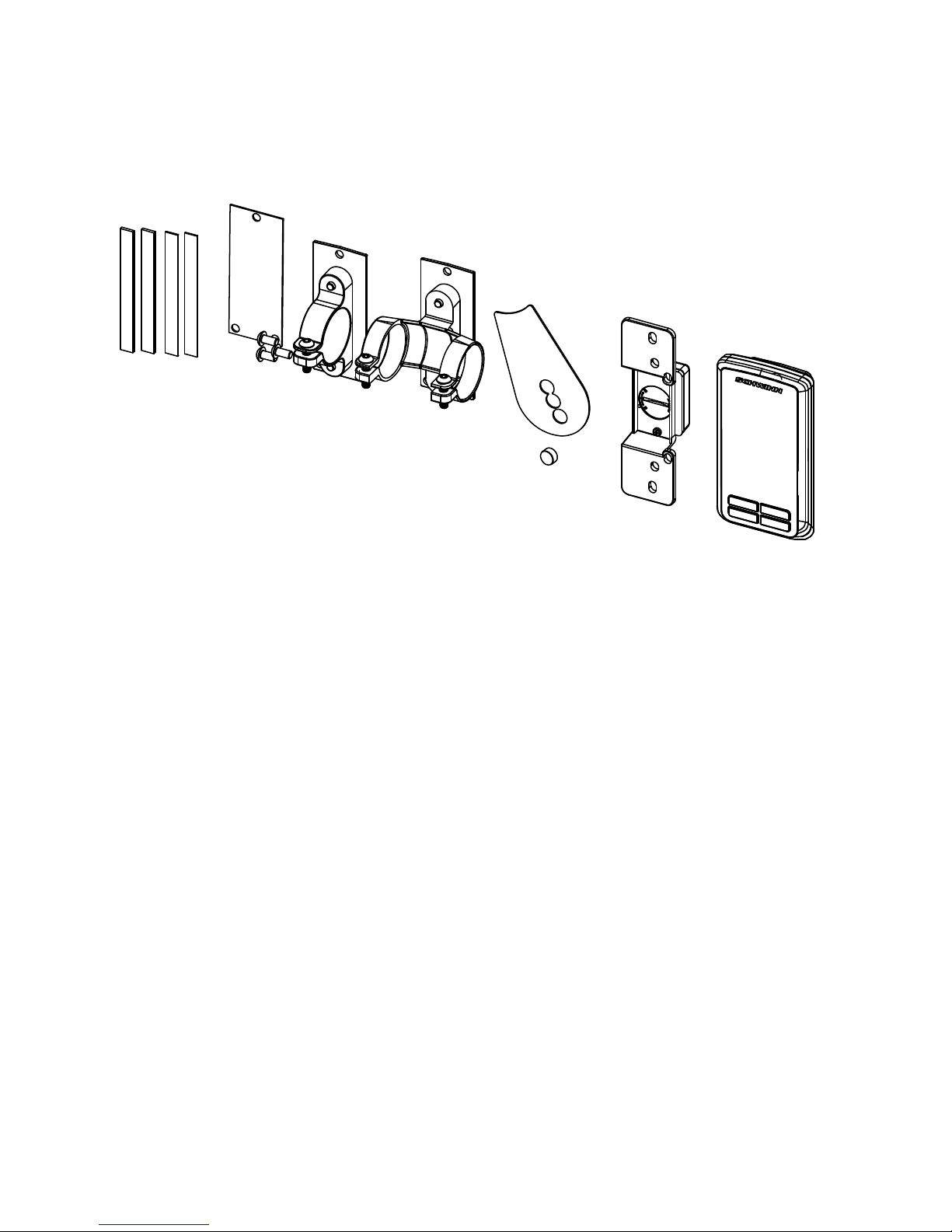
Components in the Box:
Tools Required for Assembly:
1- Phillips Head Screwdriver
2- 3mm Allen Key
DESCRIPTION QTY
MAGNET MOUNT ..............................................................................1
MAGNET
............................................................................................1
SPEED SENSOR
...............................................................................1
COMPUTER CONSOLE
....................................................................1
RUBBER SHIMS
...............................................................................4
MANUAL
.............................................................................................1
SILICONE SEAL
.................................................................................1
CONSOLE MOUNTING BOLTS
.........................................................3
SINGLE RING MOUNT
......................................................................1
DOUBLE RING MOUNT
....................................................................1
Page 4

4
Installation & Instructions
Group Cycle Computer Console
Specifications
Features:
• ANT+ interoperable 2.4Ghz wireless technology
• Low power consumption for long battery life
• Code memory during battery displacement
• Triple data display; Cadence, Heart rate and Training data
• Automatic Scan function
• Advanced energy expenditure algorithm for personalized KCALS
(Calories)
• Bright LED screen light
• Dual mode ANT+ and heritage 5.4Khz analogue Fit1e heart rate
receiver
• FCC ID: QSWASPDCS
• CE Compliant
• ANT+ Certified
• RoHS Compliant
General:
• ANT+ 2.4 GHz wireless radio to transmit data
• Batteries Required:
- Console uses 3-AAA batteries
- Flywheel transmitter uses 1 CR2032 lithium coin cell battery
- Life of batteries depends on usage
Warranty:
One year warranty on computer and transmitter.
Warranty excludes batteries.
Customer Support:
Maintenance
We strongly recommend performing the regular daily, weekly and monthly
preventive maintenance routines outlined below. If any items need re-
placement contact Customer Support Department at 1-888-678-2476.
D= Daily W= Weekly M= Monthly
D W M Procedure
Daily maintenance of the computer will determine its life of the
computer by how consistently it is performed.
• Wipe down the computer with a soft cloth after each use.
• Dilute Simple Green (1) with water (30) (30:1 ratio) spray
• Never use abrasive cleaning liquids or oil base, ammonia or
The weekly maintenance should focus on the overall
performance of the computer. During this portion of the
maintenance look for vibration and possible loose assemblies.
• Inspect each computer for loose parts, bolts and nuts. Ad-
• Remove any computers that are not properly mounted or
The monthly maintenance check should be a comprehensive
inspection of the overall assembly components of the computer.
• inspect all areas for proper adjustments.
• Inspect all parts to determine damage which will require pos-
• Battery Low will display when the battery needs replacement.
• Inspect the mounting of the cade
NOTE: Depending on the amount of use, some procedures may need to be
performed more frequently.
If any items need replacement, contact your distributor or the Customer
Support Department at 1-888-678-2476.
kHz
On Screen Features:
• RPM; Current & session average
• Heart rate; Current, session Average and % of Maximum heart rate
• Training data; Exercise session time and equivalent distance traveled
• Personalized session KCALS (Calories)
• Low
Battery Indicator
Page 5

5
Installation & Instructions
Federal Communication Commission Interference Statement
This device complies with Part 15 of the FCC Rules. Operation is subject to the
following two conditions: (1) this device may not cause harmful interference,
and (2) this device must accept any interference received, including interference that may cause undesired operation.
Changes or modifications not expressly approved by Star Trac could void the
user’s authority to operate the equipment
FCC ID: QSWASPDCS
Certifications
EU Declaration of Conformity
This device complies with the essential requirements of the R&TTE Directive
1999/5/EC.
Installation & Instructions
Federal Communication Commission Interference Statement
This device complies with Part 15 of the FCC Rules. Operation is subject to the
following two conditions: (1) this device may not cause harmful interference,
and (2) this device must accept any interference received, including interfer-
ence that may cause undesired operation.
Changes or modifications not expressly approved by Star Trac could void the
user’s authority to operate the equipment
FCC ID: QSWASPDCS
Group Cycle Computer Console
Certifications
EU Declaration of Conformity
This device complies with the essential requirements of the R&TTE Directive
1999/5/EC.
ANT+TM Performance Console is ANT+ certified.
NOTE: The users’ device must be ANT+ compatible and capable of receiving the data
les broadcast by the ANT+ chip. Users should consult with the documentation for their
device, or check the ANT+ website at www.thisisant.com for compatibility
Cadence Pro
Computer
Page 6
6
Fig. 1
Schwinn® IC Pro
TM
Schwinn® AC Sport
TM
Schwinn® AC Performance Plus
TM
Schwinn® IC PRO
20
TM
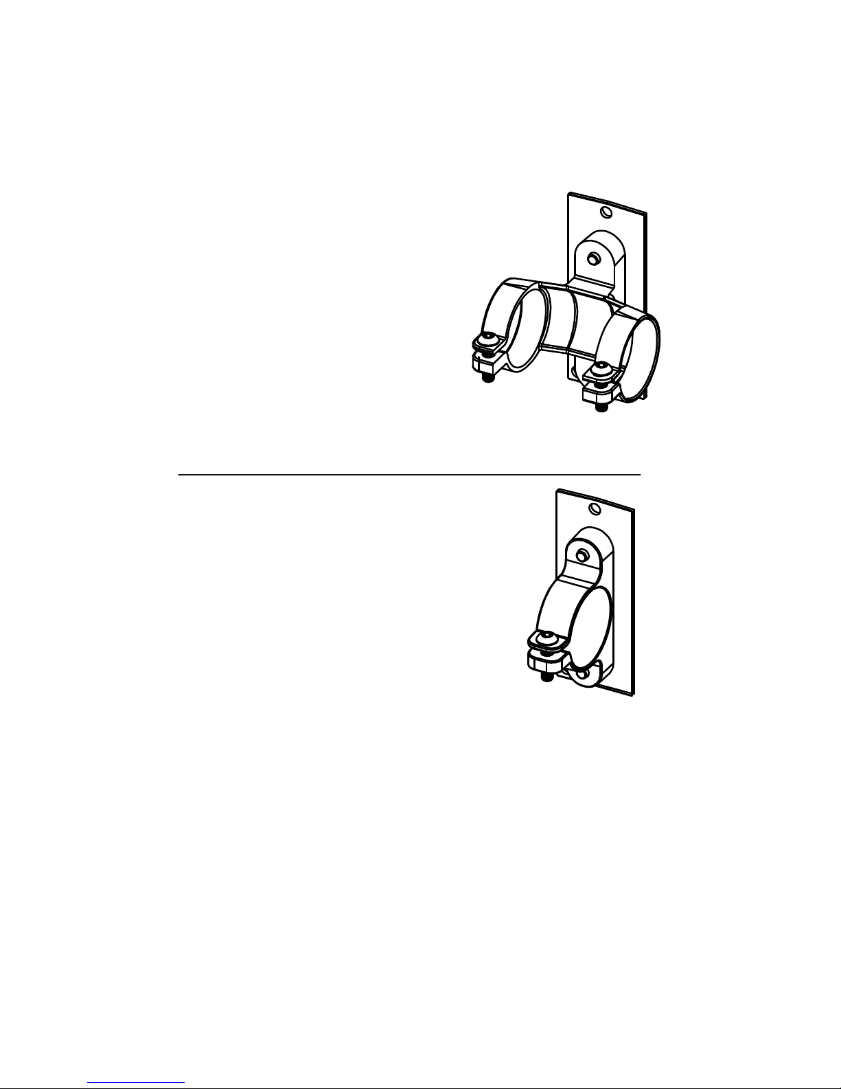
Fig. 2
Cadence Pro Computer
Bracket Mount Compatibility:
The following products can have the
Cadence Computer installed using
the clamp bracket setup shown in
(Fig.1).
The following products can have
the Cadence Pro Computer installed using the clamp bracket
setup shown in (Fig 2).
Page 7

7
IC PRO
20
1.Take the Cadence Pro Computer and silicone seal (Fig. 1). Line up the silicone seal
to the proper holes and apply it to the Cadence Pro Computer. (Fig. 2).
Fig. 1
2. Place the 2-loop mount on the back of the computer and tighten the 3 screws to the
computer (Fig. 3).
Tools Required
• 3mm Hex Key
• Philips Screw Driver
• Cadence Pro Computer Kit PN 740-8803
Page 8

8
5. Unscrew chain guard screws to use for sensor mount (Fig 7).
Fig. 5
Fig. 7
Fig. 6
Note: On the IC Pro 20, computer can be
mounted on the fore or after cross bar
3. Unscrew screws that hold the loops together (Fig 4).
4. Wrap the loops around the handlebar. (Fig. 5 & Fig. 6). NOTE: If loops do not fit
snugly around the handlebars, use the rubber shims to take up the slack.
Page 9

9
6. Install the sensor, screw on the top and bottom screw (Fig. 8).
7. Peel off the adhesive patch (Fig. 9).
Fig. 8
Fig.10
Fig. 9
Fig. 11
8. Place plastic piece so that the curve at the bottom sits against the axle hub (Fig. 10).
9. Turn ywheel to verify the light on the sensor lights up (Fig. 11).
10. Set gear ratio, see pg 18.
Page 10

10
IC PRO
Tools Required
• 3mm Hex Key
• Philips Screw Driver
• Cadence Pro Computer Kit PN 740-8803
1.Take the Cadence Pro Computer and silicone seal (Fig. 1). Line up the silicone seal
to the proper holes and apply it to the Cadence Pro Computer. (Fig. 2).
2. Tighten the 3 screws to the computer (Fig. 3).
Page 11

11
5. Unscrew top and bottom chain guard screws to use for sensor mount (Fig 7).
Fig. 5 Fig. 6
Fig. 7
3. Unscrew screws that hold the loops together (Fig. 4)
4. Insert clip on to the handlebar computer facing upwards (Fig. 5 & Fig. 6).
NOTE: If
loops do not fit snugly around bars, use the rubber shims to take up the slack.
Page 12

12
6. Take the sensor, screw on the top and bottom screw (Fig. 8).
7. Peel off the adhesive patch that holds the magnet to the ywheel (Fig. 9). Place plastic
piece so that the curve at the bottom sits against the axle hub (Fig. 10).
Fig. 8
Fig. 9
Fig. 11
Fig. 10
8. Turn ywheel to verify the light on the sensor lights up (Fig. 11).
9. Set gear ratio, see pg 18.
Page 13

13
AC PERFORMANCE PLUS
Tools Required
• 3mm Hex Key
• Philips Screw Driver
• Cadence Pro Computer Kit PN 740-8803
1.Take the Cadence Pro Computer and silicone seal (Fig. 1). Line up the silicone seal
to the proper holes and apply it to the Cadence Pro Computer. (Fig. 2).
Fig. 1 Fig. 2
2. Place the one-ring mount on the back of the computer. Insert and tighten the
three mount screws (Fig. 3). Remove the screw that holds the loop together (Fig. 4)
Chain or Carbon Blue
Page 14

14
Fig. 7
4. Install the sensor, screw on the bottom left screw (Fig. 7).
NOTE: The AC Performance Plus does not need any magnet installed because it’s
pre-installed on the ywheel.
5. Set gear ratio, see pg 18.
3. Wrap the loop around the handlebar computer facing upwards (Fig. 5 & Fig. 6).
Fig. 5
Fig. 6
Page 15

15
AC SPORT
Tools Required
• 3mm Hex Key
• Philips Screw Driver
• Cadence Pro Computer Kit PN 740-8803
Fig. 1 Fig. 2
Fig. 3
2. Tighten the 3 screws to the computer (Fig. 3).
1.Take the Cadence Pro Computer and silicone seal (Fig. 1). Line up the silicone seal
to the proper holes and apply it to the Cadence Pro Computer. (Fig. 2).
Chain or Carbon Blue
Page 16

16
3. Unscrew screws that hold the loops together (Fig. 4).
4.Wrap the loops around the handlebar computer facing upwards (Fig. 5 & Fig. 6).
5. Install the sensor, screw on the bottom left screw (Fig. 7).
Fig. 7
Page 17

17
8. Turn ywheel to verify the light on the sensor lights up.
9. Set gear ratio, see pg 18.
6. Peel off the adhesive patch from the RPM sensor magnet mount (Fig. 8).
7. Place plastic piece so that the curve at the bottom sits against the axle hub (Fig. 9).
Page 18

18
S M
LM
S S
S S S S
S
E1 E2a E3a E3a-1 *1 E4a
E3b-1 E4b
E3a-2 *2 E3a-3 E3a-4 E3a-5
Remark *1: Press MODE Button for automatically pairing
*2: Press Long MODE Button for manual pairing
*3: Press Button defines as below:
S: SET Button; LS: Long press SET Button
M: MODE Button; LM: Long press MODE Button
S
E5a
(1:3.25)
(1:4.65)
Schwinn Console (ZM6-S) Function Flow Chart (Engineering Mode)
Date: 2015/2/25
Press any key before battery enter
SET Button
MODE Button
Start/Pause/Up
Light/ Down Button
Flow Chart A
Up/down key to select different gear ratio
ENTER AND NAVIGATE MAINTENANCE MODE
NOTE: For the IC Pro and IC Pro 20, select gear ratio 1:3.2.
For the AC Sport and ACPP Chain bike, select gear ratio 1:4.5.
For the AC Sport and the ACPP Carbon Blue, select gear ratio 1:A.65.
Page 19

19
Installation & Instructions
Using The Console
1. The top display (RPM) shows cadence in RPMs, average
RPM (AVG RPM) and low battery indicator. Cadence in RPM is the
speed of the pedal crank. The average rpm (AVG RPM) indicates the
average speed in RPMs since the start of the exercise.
2. The Middle display (HEART RATE) shows heart rate, session average
and % of maximum heart rate (MHR). The heart rate is presented in beats
per minute. Average (AVG) indicates the average heart rate since the
start of the exercise. The % of MHR display indicates exercise intensity
using the heart rate maximum formula 220-age to determine maximal
heart rate, and then current heart rate as a percentage of the maximum.
3. The bottom display (TRAINING) shows time, exercise session time, and
distance (the equivalent distance that would have been covered when
cycling on the road). To change which data is being shown press the
Mode key
STAR TRAC Group Cycle Computer Installation 9
Flywheel Transmitter Installation:
The Flywheel Transmitter can be mounted in two different locations.
Steps 10 - 13 show an external shroud mounted transmitter.
Steps 14 - 18 show an internal shroud mounted transmitter.
7.
With all bike models – Verify that the right side crank arm is
clear of any obstructions and that a clear path is available to the
inner side of the right crank arm as shown from the user left side.
8. Locate the magnet holding shim along with the magnet and mount
them directly on the inner surface of the user right side crank arm.
NOTE: It is recommended to wipe the conta
cleaner such as a diluted solution of Simple Green to remove any built-up
grime or grease residue.
9. Once the magnet is mounted; rotate cranks to ensure that the
magnet will not rub on the outer chain guard shroud.
Instructions for Cadence Pro Computer
Page 20

20
Installation & Instructions
4. To START and PAUSE the timer press the start/pause/up key
To reset the timer press and hold the Mode key This
can be done when displaying any TRAINING session.
5. SCAN feature:
To use the SCAN feature press the Mode key 3 times until
(SCAN) appears in the TRAINING display. This will automatically change
between TRAINING data in intervals of 3 seconds showing: DISTANCE,
TIME and KCAL.
To stop the SCAN feature press the Mode key The SCAN
symbol should have disappeared.
Page 21

21
Installation & Instructions
Pairing Flywheel Transmitter to Console
1. Begin with one battery removed from the console.
2. Insert the battery while pressing and holding any of the four ke ys on the
front of the console. The display will now show the maintenance screen.
3. Press the Set key which will show (CAD) in the middle display
and (E01) in the top display.
4. Press the Set Key again, which will show (CAD) in the middle
display, (0) in the top RPM display and (0000) in the bottom display.
NOTE: The bottom display may already show the pairing code, but this
procedure should still be completed.
5. To pair automatically press the Mode key The 4-digit alphanumeric code should match the code on the side of the cadence transmitter and the back of the console.
6. If needed, a manual pairing can be done by pressing and holding the
Mode key The first digit of the 4 digit code (0000) should be
flashing. Adjust the digit using the up key or down key
7. Press Set key after each digit has been paired to the transmitter.
8. Press Set key and select distance in (KM) or
(Miles) by using the up key or down key
9. Press Set key to finish and begin exercise.
10. Return to page 3 and complete the remaining
installation and setup procedures.
NOTE: Once the pairing has been completed, the
code is stored in the onboard memory so that the
code is retained during a battery change, avoiding
the need to re-pair.
STAR TRAC Group Cycle Computer Installation 7
Computer Mounting:
2. With cap removed - install TWO of
the AAA batteries inside the console
(Fig. 5).
BEFORE Installing the third
battery, follow the instructions
on page 10 for Pairing the Fly-
wheel Transmitter to Console.
1. Locate the Group Cycle Computer
Console and Flywheel Transmitter
(Fig. 4). Prior to installing the
batteries, note the pairing code on
the back of the Console and Fly-
wheel Transmitter. Use this number
to check for proper pairing begin-
ning in step 2.
AFTER completing the
steps for pairing the
console to the transmit-
ter from page 10, con-
tinue with installation
and set-up.
3. Insert and close battery cap
as illustrated in (Fig. 6).
Page 22

22
Installation & Instructions
Pairing Chest Transmitter to Console
1. From sleep mode press any key, this will activate the console.
2. Press and hold Set key this will display heart rate and ANT+
symbol.
3. For automatic pairing press Mode Key this will display a four
digit code below the stated heart rate. (For heart rate pairing you must be
wearing the chest belt and move to within 12” (30cm) to the console
marked with the ANT+ symbol.
4. Once heart rate has been paired press Set key to input personal
data settings, and adjust the digit using the up key or down
ke
y
For ANT+ chest transmitter the code is alphanumeric; if an analogue 5.3Khz
transmitter is used 4 zero digits (0000) will appear.
Once the chest transmitter and console have been paired, the heart rate
reading will appear in the middle frame of the display. If pairing is unsuccessful after 20 seconds, or if heart rate reading is incorrect, move closer to the
console and press Mode key to repeat the procedure.
Page 23

23
Installation & Instructions
Personal Data Settings and Chest Transmitter Pairing
The product comes with three default settings:
Age (AGE): 30
Ambient heart rate* (AHR): 70 bpm
Weight (WT) Kg/Ibs): 70kg (154 Ibs)
1. Press Set key to set age (AGE) adjust using the up key
or down key.
2. Press Set key to set ambient heart rate* (AHR) adjust using
the up key or down key
3. Press Set key to set weight (WT) in (Kg /Ib) adjust using
the up key or down key.
4. Press Set key to finish and return to main display.
* Ambient Heart Rate is your normal heart rate during the day when you are
going about your day-to-day activities, but not exercising.
Once complete the personal data is stored in the console memory, this can
be changed or modified during exercise or when paused by pressing and
holding Set key
The chest transmitter has to be paired to the console prior to starting the exercise to achieve accurate results, and must be paired again before the start
of every new exercise.
If the display turns off automatically after 5 minutes without any activity, then
the console has entered sleep mode. The personal settings data will return to
the default settings.
STAR TRAC Group Cycle Computer Installation 5
Federal Communication Commission Interference Statement
This device complies with Part 15 of the FCC Rules. Operation is subject to the
following two conditions: (1) this device may not cause harmful interference,
and (2) this device must accept any interference received, including interfer-
ence that may cause undesired operation.
Changes or modifications not expressly approved by Star Trac could void the
user’s authority to operate the equipment
FCC ID: QSWASPDCS
Group Cycle Computer Console
Certifications
EU Declaration of Conformity
This device complies with the essential requirements of the R&TTE Directive
1999/5/EC.
ANT+TM Performance Console is ANT+ certified.
Page 24

24
Installation & Instructions
Maintenance
We strongly recommend performing the regular daily, weekly and monthly
preventive maintenance routines outlined below. If any items need replacement contact Customer Support Department at 1-888-678-2476.
D= Daily W= Weekly M= Monthly
D
W M Procedure
Daily maintenance of the computer will determine its life of the
computer by how consistently it is performed.
• Wipe down the computer with a soft cloth after each use.
• Dilute Simple Green (1) with water (30) (30:1 ratio) spray
onto a soft cloth then wipe the computer console.
NOTE: Never spray directly onto the computer console.
• Never use abrasive cleaning liquids or oil base, ammonia or
alcohol when wiping down the computer.
The weekly maintenance should focus on the overall
performance of the computer. During this portion of the
maintenance look for vibration and possible loose assemblies.
• Inspect each
computer for loose parts, bolts and nuts. Ad-
just as necessary.
• Remove any computers that are not properly mounted or
deemed unsafe.
The monthly maintenance check should be a comprehensive
inspection of the overall assembly components of the computer.
• inspect all areas for proper adjustments.
• Inspect all parts to determine damage which will require possible part replacement.
• Battery Low will display when the battery needs replacement.
Replace the batteries in the computer with 3 high quality AAA
Alkaline batteries such as Duracell or Energizer.
• Inspect the mounting of the cade
nce t
ransmitter and magnet
to insure it is intact and working properly.
NOTE: Depending on the amount of use, some procedures may need to be
performed more frequently.
Page 25

25
Installation & Instructions
Frequently Asked Questions:
What are the Personal Data Settings for use at HOME and in a CLUB?
HOME setting should be followed using the procedures indicated starting
on page 23. Imputing you AGE, AHR and WT will give you the most accurate estimate of caloric expenditure on the bike.
CLUB•
•
setting could either be done buy entering your own personal data as
indicated in the instructions on page 23 or by using the DEFAULT settings
within the bikes computer.
NOTE: Using the computers default setting may not accurately represent your
own caloric expenditure.
What is Ambient Heart Rate (AHR)?
Ambient Heart Rate (AHR) is your normal heart rate duri
ng the day when you
are going about your day-to-day activities, but not exercising. You can calculate
your AHR while you are sitting and reading a book, watching TV, working on the
computer, etc. Take your Ambient Heart Rate for 3 days to determine your
average AHR.
How does Ambient Heart Rate (AHR) differ from Resting Heart Rate
(RHR)?
Resting Heart Rate (RHR) is your heart rate when you are in a complete state
of rest. It is usually taken in the morning after awaking and before arising from
bed. Whereas Ambient Heart Rate (AHR) is your normal heart rate during the
day as you are going about your
normal day-to-day activities. AHR for the general population is generally in the 70’s. World class athletes AHRs are in the
40’s and 50’s.
What are the Group Cycle Computers Default Settings?
When the rider does
not enter their own personal data for calculation of caloric
expenditure, the computer will use its preprogrammed Default settings.
The three Default setting are: Age (AGE): 30, Ambient Heart Rate (AHR): 70
bpm, Weight (WT) Kg/lb): 70 kg (154 lbs).
What if I Do Not want other riders to know my Personal Data Settings?
Inputting your personal data is the most accurate method for calculating an estimate of caloric expenditure. This information will NOT be stored and the Group
Cycle Computer will revert back to the Default setting when it turns off, 5 minutes after the riding session or when left alone for 5 minutes.
In the Heart Rate
display, what does the %MHR mean and what is that
number?
The Group Cycle Computer will automatically determine your predicted Maximal
Heart Rate (MHR) when you input your personal data during the setup. The %
of MHR display indicates exercise intensity using the formula 220-age to represent 100%, and then current heart rate as a percentage of the maximum.
Components in the Box:
Silicone Seal for Flat Bracket
Flywheel Transmitter Foam Holder
(Foam holder for Internal Transmitter Mounting)
25mm Mounting Bolts and Spacers
(used with older handlebar design)
Double Stick Adhesive for Transmitter Mounting 1
Tools Required for Assembly:
1. Phillips Head Screwdriver
2. 3mm Allen Key
Page 26

26
Installation & Instructions
The computer is not picking up my heart rate
Make sure that the heart rate strap is fitted snuggly at the bottom of your
ribcage and that the sensors are slightl y moi s te ned .
The battery in the strap might be low, try another strap.
Try using the MODE Key (Bottom Left) for automatic pairing with the com-
puter. For Analog straps the displayed code will be 4-digits and displayed
as 0000. For ANT+ chest straps the code will be alphanumeric.
Check your distance from the computer during syncing to make sure your
12” (30cm) or closer.
Cycle through the personal data screens twice and attempt to pair again.
Which heart rate straps work with the Group Cycle Com puter?
Any ANT+ compatible HR strap will work, pairing to an ANT+ strap will
prevent any heart rate “crosstalk”.
Any analogue 5.3 KHz heart rate strap such as Polar
®
HR will work.
I am picking up another riders heart rate
If bikes and riders are close together while wearing analog heart rate straps, it
is possible to have heart rate “crosstalk” where the signal from another rider is
shown on an adjacent console. Using ANT + heart rate straps will prevent this
problem. You can also try moving the bikes further apart.
What factors affect the battery life of the computer?
Excessive use of the back light will diminish battery life.
The computer timer is not working or is not running.
Press the Play/Pause/Up key (Upper Right), the timer may be in PAUSE mode.
The computer is not scanning between the Distance, Time and KCALs.
To use the SCAN feature, press the MODE key (bottom left) 3 times until
(SCAN) appears in the TRAINING display. This will automaticall y change between the 3 data measures in intervals of 3 seconds.
What batteries does the Computer and Flywheel Transmitter take?
The computer console requires three AAA batteries. The flywheel transmitter
requires one CR2032 lithium coin cell battery.
Page 27

27
Page 28

For more information visit SchwinnEquipment.com
or call 1-888-678-2476
Group Cycle Computer
Installation Instructions
 Loading...