

Page 1
Selection Guide
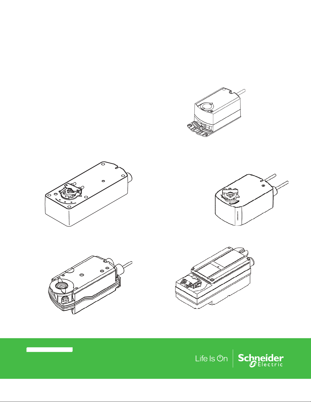
SmartX Mx4x-6xxx, Mx4x-7xxx
Series Actuators and Accessories
Applications
Direct-coupled SmartX Actuators are designed to accept twoposition, floating, or proportional control from a DDC system
or from a thermostat, for control of HVAC applications. The
actuators are designed to be used in both damper and valve
control applications. Typical applications include air handling
units, unit ventilators, fan coil units, VAV terminals, control
dampers, inlet guide vanes, and linked valve assemblies.
Use the following guide to select actuators for damper
applications. Refer to the Applicable Literature table for valve
literature.
Mx41-707x
Mx41-715x
Mx41-6043
Mx41-6083
Mx40-704x
Mx41-634x
Mx41-6153
© 2019 Schneider Ele ctric . All rig hts res erve d. All tradema rks are o wned by S chneid er Elect ric Industries SAS o r its af filia ted comp anies. May, 2019 tc
Docume nt Number: F-26 646 -12
Mx40-717x
Page 2
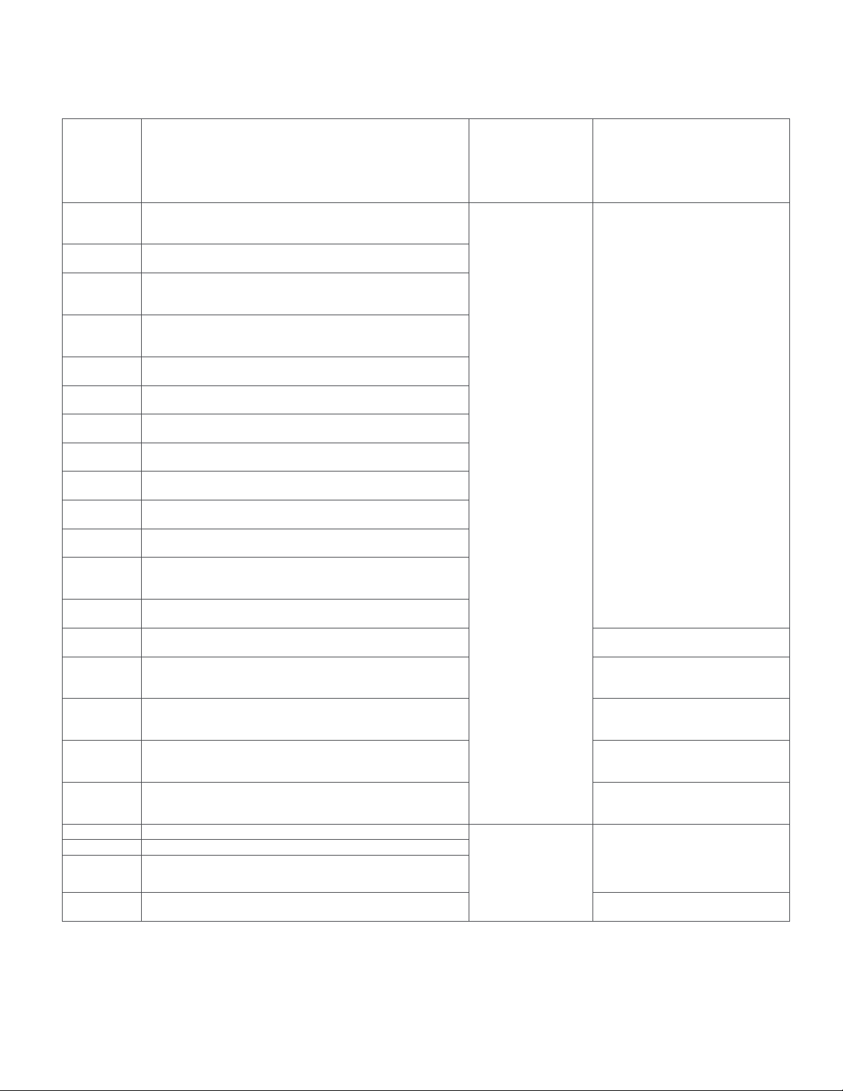
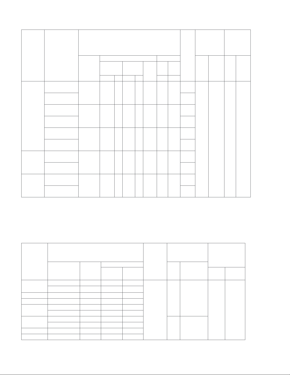
Applicable Literature
Selection Guide
F-Number Description Audience
F-27211
F-27212
F-27213
F-27214
F-27215
F-26744
F-26745
F-26742
F-26748
F-26749
F-26644
F-26642
F-26645
F-27160
F-26750
F-27087
F-26752
F-27086
F-11080 Valve Selection Chart Water
F-11366 Valve Selection Chart Steam (two-way valves only)
F-13755 CA-28 Control Valve Sizing
F-26080 EN-205 Water System Guidelines
MF41-6043/MS41-6043 Series,
MF41-6083/ MS41-6083 Series Non-Spring Return Direct Coupled Actuator Installation Instructions
MF41-6153, MS41-6153 Non-Spring Return Direct Coupled
Actuator Installation Instructions
MF41-6043/MF41-6083 Series Non-Spring Return Rotary 24Vac
Three-Position Control Electronic Damper Actuators General
Instructions
MS41-6043/MS41-6083 Series Non-Spring Return Rotary 24Vac
Modulating Control 0…10Vdc Electronic Damper Actuators
General Instructions
MF41-6153/MS41-6153 Series Non-Spring Return Rotary Electronic Damper Actuators General Instructions
MF41-6343 SmartX Series Non-Spring Return Direct Coupled
Actuator General Instructions
MS41-634x SmartX Series Non-Spring Return Direct Coupled
Actuator General Instructions
MA40-717x SmartX Series Spring Return Direct Coupled Actuator General Instructions
MS40-717x SmartX Series Spring Return Direct Coupled Actuator General Instructions
MF40-7173 SmartX Series Spring Return Direct Coupled Actuator General instructions
MF4x-7xx3, MF4x-7xx3-50x Schneider Electric SmartX Series
Spring Return Direct Coupled Actuator General Instructions
MA4x-7xx3, MA4x-7xx3-50x, MA4x-7xxx, MA4x-7xxx-50x SmartX
Series Spring Return Direct Coupled Actuator General Instructions
MS4x-7xx3, MS4x-7xx3-50x SmartX Series Spring Return Direct
Coupled Actuator General Instructions
Mx4x-6xxx-220/-230 and Mx4x-7xxx-220 Actuator/Linkage Assemblies for 2-1/2”…6” Globe Valves General Instructions
MA4x-xxxx-2xx, MF4x-xxxx-2xx, MS4x-xxxx-2xx Series Actuator/
Linkage Assemblies for 1/2”…2” Globe Valves General Instructions
Vx-2x13-5xx-9-xx Series, VB-2x13-500-9-xx Series Ball Valve
Assemblies and Ball Valve Body/Linkage Assemblies Installation
Instructions
Vx-7000 and Vx-9000 Series, Mx4x-6xxx and Mx4x-7xxx Series,
Linked Globe Valve Assemblies and Actuator/Linkage Assemblies with SmartX Actuators Selection Guide
Vx-2x13-5xx-9-xx Series Ball Valve Assemblies and VB-2x13500-9-xx Series Ball Valve Body/Linkage Assemblies Selection
Guide.
Sales Personnel
Application Engineers.
Other details:
Installers
Service Personnel
Start-up Technicians
Installers
Service Personnel
Start-up Technicians
Purpose
All documents describe actuator
features, specifications, possible applications, and step-by-step mounting
instructions. Other details:
Also provides checkout instructions.
Globe Valves
Ball valves
Linked Globe Valve assemblies with
SmartX actuators.
Linked Ball Valve assemblies with
SmartX actuators.
Provides charts, equations, and
diagrams to assist in the configuration
of valve system applications. TOOL150, valve sizing slide rule may be
purchased separately.
Describes Schneider Electric approved water treatment practices.
May, 2019 tc © 2019 Schneider Ele ctric . All rig hts res erve d. All tradema rks are o wned by S chneid er Elect ric Industries SAS o r its af filia ted comp anies.
Document Number: F-2664 6-12
Page 3
Selection Guide
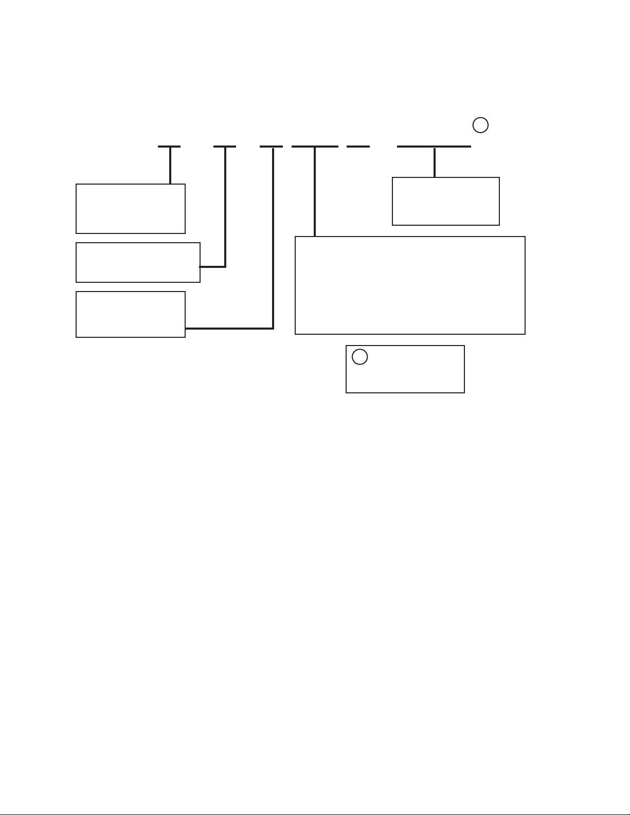
Actuator Part Numbering System
M X 4 X - X X X X - X X X
1
Control Signal Type
A = Two position
F = Floating
S = Propor tional
Rotation Positioning
0 = Non-Manual Override
1 = Manual Override
Spring Return Action
6 = Non-Spring Return
7 = Spring Return
Supply Voltage
0 = 120 Vac
1 = 230/240 Vac
3 = 24 Vac
Torque Rating
04 = Mx40 and MA41 models: 35 lb-in. (4 Nm)
MS41 and MF41 models: 44 lb-in. (5 N-m)
07 = 60 lb-in. (7 N-m)
08 = Mx40 and MA41 models: 70 lb-in (8 N-m)
MS41 and MF41 models: 88 lb.in (10 N-m)
15 = 133 lb-in. (15 N-m)
17 = 150 lb-in. (17 N-m)
34 = 300 lb.in (34 N-m)
Consult the Actuator
1
Selection Chart and
the Actuator Accessories
Chart for available models.
© 2019 Schneider Ele ctric . All rig hts res erve d. All tradema rks are o wned by S chneid er Elect ric Industries SAS o r its af filia ted comp anies. May, 2019 tc
Docume nt Number: F-26 646 -12
Page 4
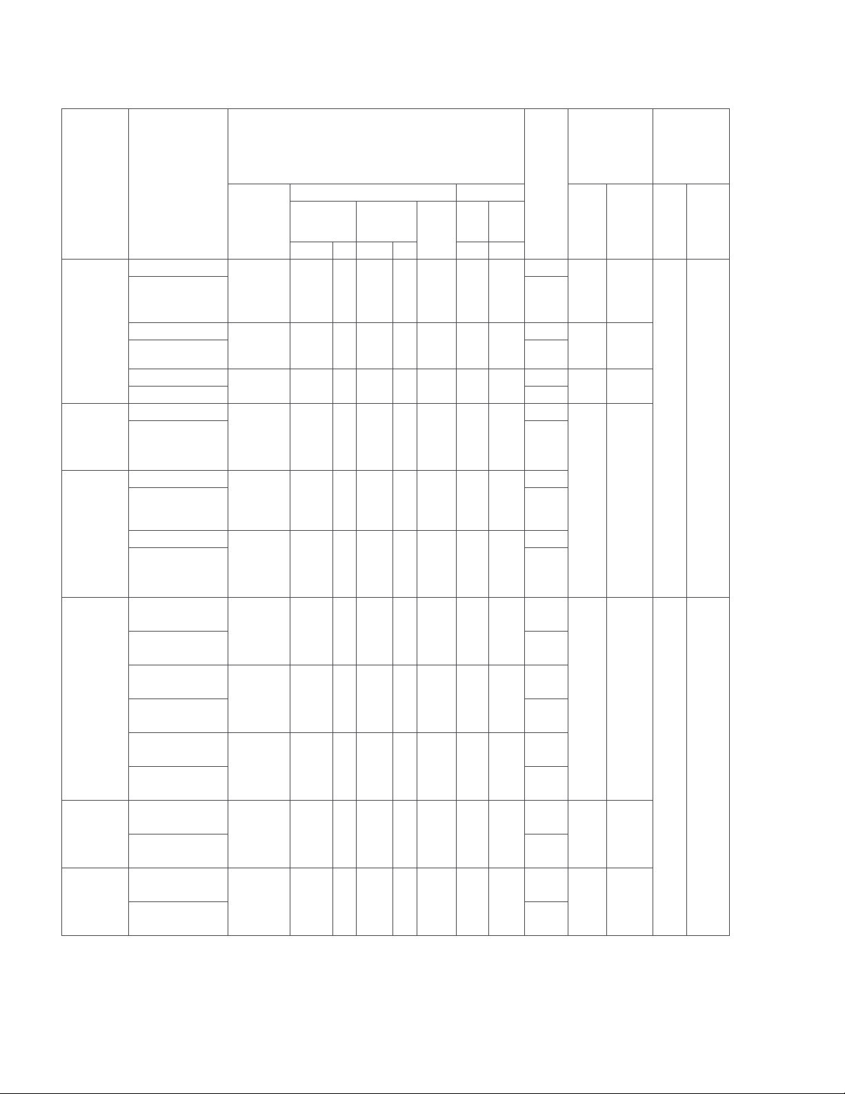
Table 1. Mx40-704x, Mx4x-707x, and Mx4x-715x
Selection Guide
Actuator
Type
Two-
Position
Floating
Proportional
Power Input
Part Numbers
Voltage
50 Hz 60 Hz
Running Holding
50
DC
Amps
Hz
60
Hz
VA W VA W W W
MA40-7043
MA40-7043-501 1
24 Vac ±
20%
22…30
4.4 2.9 4.4 2.9 0.11 0.8 0.8
Vdc
MA40-7040
MA40-7040-501 1
MA40-7041
MA40-7041-501 1
MF40-7043
MF40-7043-501
c
120 Vac ±
10%
230 Vac ±
10%
24 Vac ±
20%
22…30
6.4 3.8 4.3 3.4 — 1.6 1.2
5.8 4.1 4.6 3.9 — 1.5 1.2
5.9 4.4 5.9 4.4 0.17 2.9 2.9
Vdc
MS40-7043
MS40-7043-501
c
c
24 Vac ±
20%
22…30
5.6 4.2 5.6 4.2 0.15 2.4 2.4
Vdc
MS40-7043-MP
24 Vac
MS40-7043-MP5 1
22…30
Vdc
6.6 5.0 6.6 5.0 0.17 3.2 3.2
Approx. Timing
(sec.) @ 70 °F
(21 °C) with No
Switches
SPDT Auxiliary
-
<50 <26
<50 <26
b
<50 <26
b
-
b
1
-
<130 <25
b
1
-
b
Load
Powered
Spring
Return
Output
Torque
Rating
lb.-in. (N-m)
Max.
Min.
Stall
35
150
(4)
(17)
Two-
Position
Floating
Proportional
MA41-7073
MA41-7073-502
MA41-7070
d
MA41-7070-502
MA41-7071
d
MA41-7071-502
MF41-7073
d
MF41-7073-502
MS41-7073
d
MS41-7073-502
d
d
d
d
d
24 Vac ±
20%
22…30
Vdc
120 Vac ±
10%
230 Vac ±
10%
24 Vac ±
20%
22…30
Vdc
24 Vac ±
20%
22…30
Vdc
4.8 3.2 4.8 3.2 0.13 0.8 0.8
10.7 4.2 5.6 3.6 — 2.0 1.2
17.0 5.1 8.0 4.0 — 2.7 1.4
6.2 4.8 6.2 4.8 0.18 2.8 2.8
5.8 4.6 5.8 4.6 0.17 2.3 2.3
-
2
-
e
2
-
e
2
-
e
2
-
e
2
<80 <40
<195 <30
<195 <30
60
(7)
250
(28)
May, 2019 tc © 2019 Schneider Ele ctric . All rig hts res erve d. All tradema rks are o wned by S chneid er Elect ric Industries SAS o r its af filia ted comp anies.
Document Number: F-2664 6-12
Page 5
Selection Guide
Actuator
Part Numbers
Type
Voltage
50 Hz 60 Hz
VA W VA W W W
MA40-7153
MA41-7153
d
MA40-7153-502
MA41-7153-502
Two-Position
MA40-7150
MA41-7150
MA40-7150-502
d
MA41-7150-502
MA40-7151
MA41-7151
d
MA40-7151-502
MA41-7151-502
Floating
MF40-7153
MF41-7153
MF40-7153-502
d
MF41-7153-502
Proportional
MS40-7153
MS41-7153
MS40-7153-502
d
MS41-7153-502
a - De-rating required for spring return actuators at low temperatures.
b - One adjustable from 15…95° rotation (MIN…1 scale).
c - With plenum-rated cable.
d - Equipped with manual override.
e - One adjustable from 25°…85° rotation and one set to operate @ 5° fixed.
d
d
d
d
d
24 Vac ±
20%
22…30
Vdc
120 Vac ±
10%
230 Vac ±
10%
24 Vac ±
20%
22…30
Vdc
24 Vac ±
20%
22…30
Vdc
9.8 7.5 9.7 7.5 0.29 2.8 2.8
11.7 8.8 10.0 8.4 — 3.6 5.0
15.5 9.5 10.6 8.5 — 4.6 3.3
9.8 7.7 9.7 7.7 0.30 3.3 3.3
9.8 7.4 9.7 7.4 0.28 2.9 2.9
Power Input
Running Holding
50
DC
Amps
Hz
60
Hz
SPDT Auxiliary
No
Two
No
Two
No
Two
No
Two
No
Two
Switches
e
e
e
e
e
Approx. Timing
(sec.) @ 70 °F
(21 °C) with No
Load
Spring
Powered
Return
<190 <30
Output
Torque
Rating
lb.-in. (N-m)
Max.
Min.
Stall
133
350
(15)
(40)
Table 2. Mx40-717x Series Spring-Return Actuators
De-rating required for spring return actuators at low temperatures.
Power Input @ 50/60Hz
Part
Numbers
MA40-7173
Voltage
Running
Watts
Running Holding Min. Max. Stall
24 Vac ± 20% 5.3 7.4 5.1
22…30 Vdc 5.0 5.0 3.0
VA
MA40-7170 120 Vac ± 10% 6.2 8.4 6.6
MA40-7171 240 Vac ± 10% 6.5 9.8 8.5
MF40-7173
MS40-7173
24 Vac ± 20% 5.8 8.1 5.3
22…30 Vdc 5.7 5.7 3.6
24 Vac ± 20% 5.5 7.8 4.7
22…30 Vdc 5.0 5.6 2.5
MS40-7170 120 Vac ± 10% 6.4 8.5 5.2
SPDT
Auxiliary
Switches
No
Sec. @ 70 °F (21 °C)
with No Load
Spring
Powered
Return
162 72
147 65
MS40-7171 240 Vac ± 10% 7.2 10.8 9.0
© 2019 Schneider Ele ctric . All rig hts res erve d. All tradema rks are o wned by S chneid er Elect ric Industries SAS o r its af filia ted comp anies. May, 2019 tc
Docume nt Number: F-26 646 -12
Approx. Timing in
Output Torque
Rating
lb.-in. (N-m)
150 (17) 545 (61.8)
Page 6
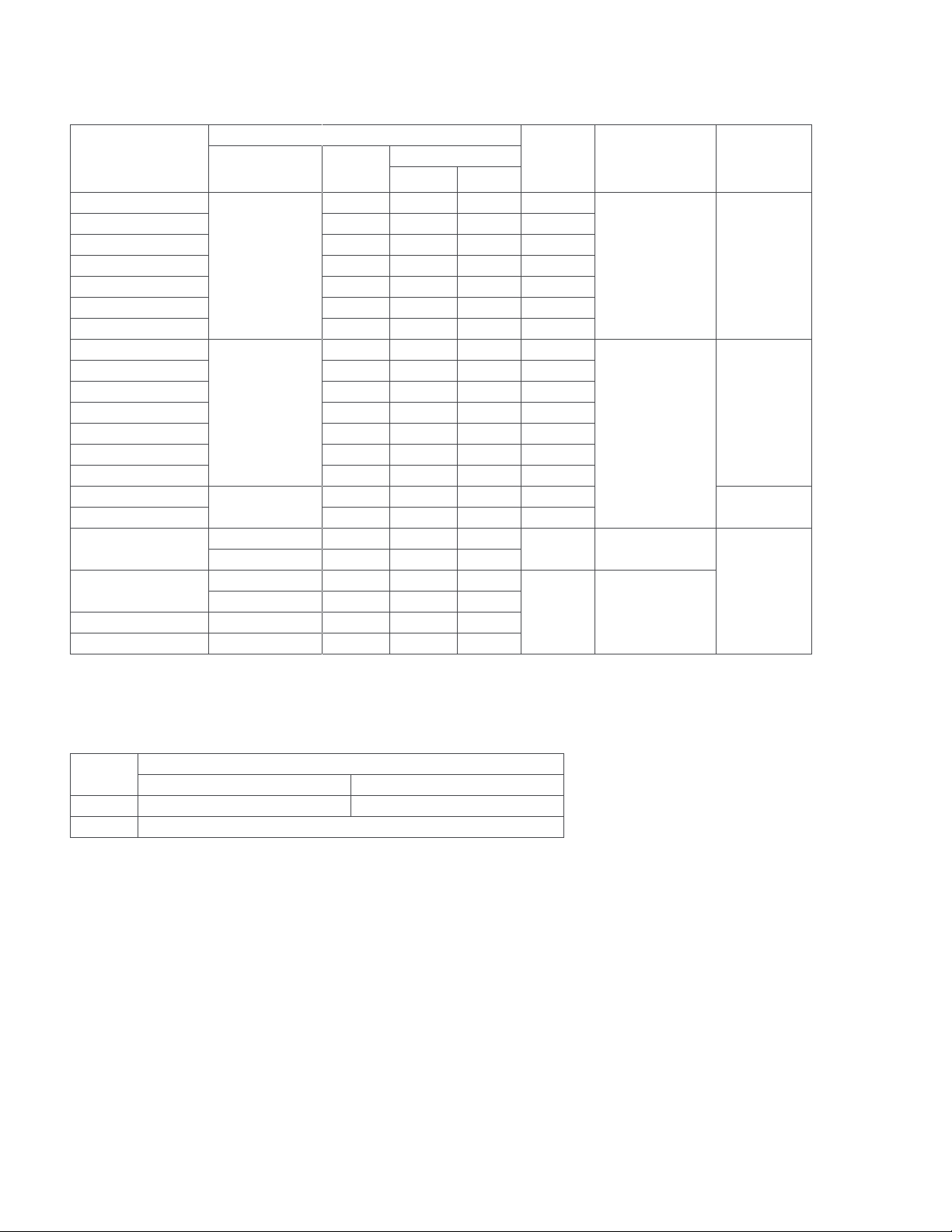
Table 3. Non-Spring Return Actuators
Selection Guide
Power Input @ 50/60Hz
Part Numbers
MF41-6043
MF41-6043-502
MF41-6043-510
MS41-6043
MS41-6043-502
MS41-6043-520
MS41-6043-522
MF41-6083
MF41-6083-502
MF41-6083-510
MS41-6083
MS41-6083-502
MS41-6083-520
MS41-6083-522
b
b
b
bc
b
b
b
bc
b
b
bc
be
bf
MF41-6153
MS41-6153 4.0 5.0 1.2 No
MF41-6343
MS41-6343
Voltage Watts
Running Holding
2.0 2.3 — No
2.0 2.3 — 2
2.0 2.3 — No
24 Vac +20/-15%
3.0 3.3 1.2 No
3.0 3.3 1.2 2
3.0 3.3 1.2 No
3.0 3.3 1.2 2
2.0 2.3 — No
2.0 2.3 — 2
2.0 2.3 — No
24 Vac +20/-15%
3.0 3.3 1.2 No
3.0 3.3 1.2 No
3.0 3.3 1.2 No
3.0 3.3 1.2 2
24 Vac +20/-15%
3.0 3.0 — No
24 Vac ± 20% 3.9 5.7 4.1
22…30 Vdc 4.1 4.1 3.0
24 Vac ± 20% 3.6 5.6 4.0
22…30 Vdc 3.4 3.4 2.2
VA
MS41-6340 120 Vac ±10% 4.7 7.5 6.2
SPDT
Auxiliary
Switches
No 162
No 148
Approximate
Timing in Seconds
@ 70 °F (21 °C)
a
with No Load
90 @ 60Hz
108 @ 50Hz
125 @ 60Hz
150 @ 50Hz
MS41-6341 240 Vac ±10% 5.0 9.0 8.1
b - Equipped with plenum-rated cable.
c - Equipped with two built-in auxiliary switches.
d - Equipped with 1k W feedback potentiometer.
e - Equipped with adjustable start/span.
f - Equipped with adjustable start/span and two auxiliary switches.
g - Minimum voltage at high temperatures: 24 Vac, +20%, -10% at 90…130 °F ambient.
h - Minimum voltage at high temperatures: 24 Vac, +20%, -5% (MF models) and 24 Vac, +20%, -10% (MS models) at 85…130 °F ambient.
a - Auxiliary switch ratings are as follows:
Actuator
Output Torque
Rating (Min.
lb.-in. (N-m)
44 (5)
g
88 (10)
h
133 (15)
300 (34)
Auxiliary Switch Ratings
Mx41-6043, Mx41-6083 Mx41-6153
AC Rating 24 Vac, 4 A resistive, 2 A inductive 24 Vac, 6 A resistive, 2 A inductive
DC Rating 12…30 Vdc, DC 2 A
May, 2019 tc © 2019 Schneider Ele ctric . All rig hts res erve d. All tradema rks are o wned by S chneid er Elect ric Industries SAS o r its af filia ted comp anies.
Document Number: F-2664 6-12
Page 7
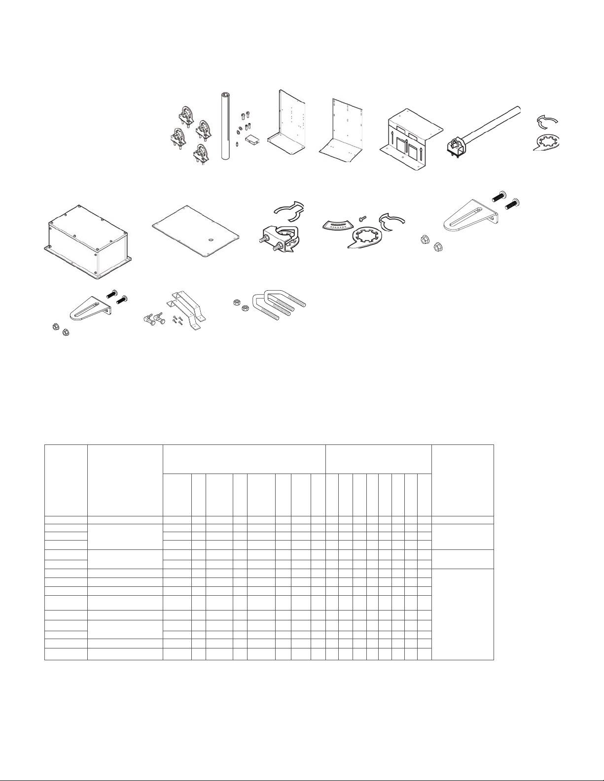
Selection Guide
Actuator Accessories
AM-621
AM-675
AM-674
AM-693-R
Actuator Accessories Table
Spring Return Actuators
(Series [x] or individuals)
Par t
Numbers
Description
AM-688
AM-692
AM-671
AM-672
AM-673
AM-689
NEW Mx41-730x ACTUATORS ACCESSORIES
AM-708 500 ohm resistor for connection to 4 to 20 mA input signals
AM-801 Mx41-730x-xxx Actuator Crank Ar m Kit
AM-802 Mx41-730x-xxx Actuator Crank Ar m Kit with Actuator Mounting Bracket and Two
AM-803 9-3/4” damper Shaft Extension for 5/16” to 1” Diameter Round Shafts
AM-804 Jackshaft Linkage (requires AM-805 Suppor t Plate for Mx41-73xx Actuators)
AM-805 Suppor t Plate for Mx41-73xx Actuators
BEL-ZTH US Handheld Interface Module for Field Programming of the MS41-7303-xxx
Ball Joints
Models
AM-676
AM-690-R
AM-686
Non-Spring Return
Actuators
(Series [x] or individuals)
Installation
Instruction
MF40-7043
MA40-704x
AM-621 Round Shaft Extension X X X X X X X X -
abcd
AM-671
abcd
AM-672
c
AM-673
AM-674
AM-675 X X X X X X
AM-676 Shaft Extension X X X X X X X X X X
AM-686 Position Indicator X X X X
e
AM-687
AM-688
AM-689 Rotation Limiter X
i
AM-690-R
AM-691 X X X X
f
AM-692
gh
AM-693-R
a - AM-693 crank arm kit required.
b - Cannot be used with Mx41-634x or Mx40-717x series actuators.
c - Drill appropriate mounting holes where needed.
d - The large “C”-shaped clamps included in AM-693 crank arm kit are required for mounting the actuator. Drill appropriate mounting holes where needed.
e - For shafts to 1.05” diameter or 5/8” square.
f - For shafts to 3/4” and 1.05” diameter (with AM-690 and AM-691, respectively).
g - Use the self-tapping screws and flat washers provided in kit to mount actuator.
h - AM-692 V-bolt kit required. The AM-693-R damper linkage kit is used in conjunction with the AM-687 or AM-688 universal clamps to provide a mechanical linkage between the damper
actuator and the damper shaft when a direct coupling is not possible.
i - Used in conjunction with the AM-687 or AM-688 universal clamps for crankarm functionality in non-direct mounting applications.
© 2019 Schneider Ele ctric . All rig hts res erve d. All tradema rks are o wned by S chneid er Elect ric Industries SAS o r its af filia ted comp anies. May, 2019 tc
Docume nt Number: F-26 646 -12
Mounting
Bracket
Weather
Shield &
Base
V-clamp X X X X
Replacement Universal
Clamp
Crank Arm Kit
V-bolt X X X X
Crank Arm Kit X X X X
X X X X X X
X X X X X X
X X X X X X
X X X X X X X X X X
MF4x-7073
MA4x-707x
MS40-7043
X X X X
X X X
X X X X
MS4x-7073
MA4x-715x
MF4x-7153
MS4x-7153
MF40-7173
MA40-717x
MF41-6043
MS40-717x
MF41-6083
MS41-6043
MF41-6153
MS41-6083
MF41-6343
MS41-6153
MS41-634x
F-25096
F-25097
F-25098
Page 8

AM-708
Selection Guide
AM-703
AM-704
AM-706
AM-712
AM-710, AM-717
AM-705
AM-709
AM-711
AM-715
AM-713
AM-714
AM-751
AM-726
AM-727
AM-728
AM-752
Actuator Accessories Table
Spring Return Actuators
(Series [x] or individuals)
Par t
Numbers
AM-703 Span Adjustment X X X X X X X
AM-704 Modulation Interface X X X X X X X
AM-705
AM-708
AM-709
a
AM-710
AM-711
AM-712 X X
AM-713 Bracket X X
AM-714 Weather Shield X X X X X X F-25097
AM-715
AM-717
AM-726
b
AM-728
AM-751
AM-752 X X X X
a - For shafts to 3/4” diameter round or up to 1/2” square.
b - Cannot be used when creating a linked valve/actuator assembly.
Description
MF40-7043
MA40-704x
Positioner
500W Resistor
Position Indicator
& Stroke Limiter
V-clamp X X
Crank Arm
Adaptor Kit
Crank Arm
Adaptor Kit
Replacement
Universal Clamp
Crank Arm Adaptor
Conduit Adaptor X X X X
Anti-rotation Bracket
X X
X X
X X F-26896
X X F-26896
MA4x-707x
MS40-7043
X X X X X X X X
X X X X X X
MF4x-7073x
MA4x-715x
MS4x-7073x
MF4x-7153x
MS4x-7153x
MF40-7173
MA40-717x
X X X X
Non-Spring Return Actuators
(Series [x] or individuals)
MF41-6043
MS40-7173
X X X X
MF41-6083
MS41-6043
MF41-6153
MS41-6083
MF41-6343
MS41-6153
MS41-634x
Instruction
Installation
F-26895
F-26895AM-706 X X X X X X X X
F-26896
F-26802AM-727 X X X X
F-26898
Document
May, 2019 tc © 2019 Schneider Ele ctric . All rig hts res erve d. All tradema rks are o wned by S chneid er Elect ric Industries SAS o r its af filia ted comp anies.
Document Number: F-2664 6-12
Page 9

Selection Guide
AM-735
AM-741
AM-753
AM-756
Actuator Accessories Table
Par t
Numbers
Description
AM-736
AM-758
Spring Return Actuators
(Series [x] or individuals)
AM-759
AM-754
AM-737
AM-760
AM-740
AM-761
& AM-762
Non-Spring Return Actuators
(Series [x] or individuals)
Instruction
Installation
Document
MF40-7043
MA40-704x
AM-735 Crank Arm Kit X X F-27246
AM-736
AM-737 Universal Crank Arm
AM-740 Replacement Kit X X F-27249
AM-741 Weather Shield X X X X X F-27250
AM-753
AM-754
AM-756 Metric Conduit Adaptor X X X X X X X X X X F-26899
AM-758
AM-760
AM-761
AM-762
TF-711-02
TF-713-02 X X X X —
TF-5521 Pipe Plug X X X X —
a - For Honeywell Floor Mount Mod Motor.
b - For shafts 3/4” round and 5/8” square.
c - For shafts 3/8”…1/2” round and square.
d - Only used on Mx41-707x-xxx, Mx41-715x-xxx.
Crank Arm Kit with
b
Mounting Clamp
c
Short “U” Mounting
Slotted “L” Mounting
7-inch Anti-Rotation
9-inch Anti-Rotation
Sealtight Conduit Con
Bracket
Bracket
Bracket
Bracket
Bracket
nector
a
X X F-26986
X X X X X X X X X X F-25098
-
MA4x-707x
MS40-7043
MF4x-7073x
MS4x-7073x
X X X X
X X X X
MA4x-715x
MF4x-7153x
MS4x-7153x
MF40-7173
MA40-717x
X X X X
X X X X
X X X X —
MF41-6043
MS40-7173
MF41-6083
MS41-6043
MF41-6153
MS41-6083
X X F-27247
X X F-27248
MF41-6343
MS41-6153
MS41-634x
F-26898
F-25096AM-759 Tall “U” Mounting Bracket X X X X
© 2019 Schneider Ele ctric . All rig hts res erve d. All tradema rks are o wned by S chneid er Elect ric Industries SAS o r its af filia ted comp anies. May, 2019 tc
Docume nt Number: F-26 646 -12
Page 10

MF41-6043 and MS41-6043 Actuators
For non-spring return applications requiring floating or proportional modulation
control of dampers and valves in HVAC systems.
Features:
• Direct mount to round, square, or hexagonal damper shaft
• Rated at 44 lb-in. (5N-m) torque, minimum
• Does not require any limit switches
• Manual override allows positioning for installation and manual operation
• MF41-6043 provides floating point control (3-position)
• MS41-6043 provides proportional control compatible with 0…10Vdc
• 5-year warranty
Selection Guide
Actuator Specifications
Inputs
Control Signal
MF41-6043 Floating three-position control, 24Vac.
MS41-6043 Proportional, 0…10Vdc; input
resistance 100kW.
Power Requirements (see table) All 24Vac circuits are Class2.
Connections 3ft. (0.9m) long,
18AWG leads, plenum-rated.
Motor Type Synchronous
Outputs
Electrical
AC Rating 24Vac, 4A resistive, 2A inductive
DC Rating 12…30Vdc, DC 2A
Timing 90sec. at 60 Hz, 108sec. at 50 Hz
Mechanical
Output torque rating 44lb-in. (5N-m).
Stroke Normal angle of rotation is 90°,
limited to a maximum of 95°
Field adjustable to limit travel on
either end of stroke. Set
or 5° preload at the factory
Position indicator Adjustable pointer is provided
for position indication. See
the Note in “Switch Range.”
Output shaft setscrew
tightening torque 55…60lb-in. (6.3…6.8N-m)
Nominal Damper Area Actuator sizing should
Environment
Temperature Limits
Shipping and storage -40…158°F (-40…70°C) ambient
Operating -25…130°F (-32…55°C) ambient
Humidity 5…95% RH, non-condensing
Enclosure Rating NEMA Type 2
Agency Listings
UL UL-873, Underwriters Laboratories.
European Community EMC Directive (89/336/EEC).
cUL Canadian Standards C22.2 No. 24-93.
Accessories
AM-726 Rotary-to-Linear Bracket
AM-727 Rotary-to-Linear Crank Arm
AM-728 Conduit Adapter
AM-741 Weather Shield Kit
Part Numbers
MF41-6043 24 Vac +20/-15% 2.3 — 2.0
MS41-6043 24 Vac +20/-15% 3.3 1.2 3.0
Voltage
damper manufacturer’s specifications
Power Input @ 50/60Hz
be done in accordance with
Emissions (EN50081-1).
Immunity (EN50081-2).
Running VAHolding
VA
Watts
Figure-1 MF41-6043 and MS41-6043 Mounting Dimensions (mm)
May, 2019 tc © 2019 Schneider Ele ctric . All rig hts res erve d. All tradema rks are o wned by S chneid er Elect ric Industries SAS o r its af filia ted comp anies.
Document Number: F-2664 6-12
Page 11

Selection Guide
MF41-6083 and MS41-6083 Actuators
For non-spring return applications requiring floating or proportional modulation
control of dampers and valves in HVAC systems.
Features:
• Direct mount to round, square, or hexagonal damper shaft
• Rated at 88 lb-in. (10N-m) torque, minimum
• Does not require any limit switches
• Manual override allows positioning for installation and manual operation
• MF41-6083 provides floating point control (3-position)
• MS41-6083 provides proportional control compatible with 0…10Vdc
• Models available with: independently adjustable dual auxiliary switches;
adjustable start point (offset) and span
• 5-year warranty
Actuator Specifications
Inputs
Control Signal
MF41-6083 Floating three-position control, 24Vac
MS41-6083 Proportional, 0…10Vdc; input
resistance 100kW.
Control signal adjustment available with MS41-6083-520 and
MS41-6083-522
Start point (offset) Between 0 and 5Vdc (factory setting = 0Vdc)
Span 2…30Vdc
Power Requirements (see table) All 24Vac circuits are Class2
Connections 3ft. (0.9m) long, 18
AWG leads, plenum-rated.
Motor Type Synchronous
Outputs
Electrical
Position output signal: Feedback potentiometer
available with MF41-6083-510 0…1000W < 10mA
Output voltage 0…10Vdc
Maximum output current 1mA
Dual auxiliary switches available with
MF41-6083-502, MS41-6083-502,
MF41-6083-522, and MS41-6083-522
AC Rating 24Vac, 4A resistive, 2A inductive
DC Rating 12…30Vdc, DC 2A
Switching hysteresis 2°
Switch Range
Switch A 0…90° range in 5° intervals
Recommended range usage 0…45°
Factory setting 5°
Switch B 0…90° range in 5° intervals
Recommended range usage 45…90°
Factory setting 85°
Timing 125sec. at 60Hz, 150sec. at 50Hz
Mechanical
Output torque rating 88lb-in. (10N-m)
Stroke Normal angle of rotation is 90°, limited to
Position indicator Adjustable pointer is provided for
Output shaft setscrew
tightening torque 55…60lb-in. (6.3…6.8N-m)
Nominal Damper Area Actuator sizing should be done in
Environment
Temperature Limits
Shipping and storage -40…158°F (-40…70°C) ambient
Operating -25…130°F (-32…55°C) ambient
Humidity 5…95% RH, non-condensing
Enclosure Rating NEMA Type 2
Agency Listings
UL UL-873, Underwriters Laboratories
European Community EMC Directive (89/336/EEC)
cUL Canadian Standards C22.2 No. 24-93
Accessories
AM-726 Rotary-to-Linear Bracket
AM-727 Rotary-to-Linear Crank Arm
AM-728 Conduit Adapter
AM-741 Weather Shield Kit
Part
Numbers
MF41-6083 24 Vac +20/-15% 2.3 — 2.0
MS41-6083 24 Vac +20/-15% 3.3 1.2 3.0
a maximum of 95°. Field adjustable to limit
Voltage
travel on either end of stroke. Set for 5°
See the Note in “Switch Range.”
accordance with damper manufacturer’s
Power Input @ 50/60Hz
Running VAHolding
preload at the factory
position indication.
Emissions (EN50081-1)
Immunity (EN50081-2)
VA
specifications
Watts
Figure 2. MF41-6083 and MS41-6083 Mounting Dimensions (mm)
© 2019 Schneider Ele ctric . All rig hts res erve d. All tradema rks are o wned by S chneid er Elect ric Industries SAS o r its af filia ted comp anies. May, 2019 tc
Docume nt Number: F-26 646 -12
Page 12

MF41-6153 and MS41-6153 Actuators
For non-spring return applications requiring floating or proportional
modulation control of dampers and valves in HVAC systems.
Features:
• Direct mount to round or square damper shaft
• 133 lb-in (15 N-m) torque rating
• Does not require any limit switches
• Manual override to allow positioning for installation and manual operation
• MF41-6153 provides floating point control (drive open-hold-drive closed)
• MS41-6153 provides proportional control compatible with 0…10 Vdc or
0…20 mA dc
• 5-year warranty
Actuator Specifications
Inputs
Control Signal
MF41-6153 Three position
MS41-6153 Proportional, 0…10Vdc, input
resistance 100kW
Power Requirements (see table) All 24Vac circuits are Class2
Connections 3ft. (91 cm) long plenum-rated
cables, 18AWG color coded leads
Motor Type Synchronous
Outputs
Electrical
Timing Approx. 125sec. at 60Hz;
150sec. at 50Hz
Dual Auxiliary Switch Ratings
AC Rating 24Vac, AC6A resistive, AC2A inductive
DC Rating 12…30Vdc, DC 2A
Switch Ranges
Switch A 0°…90° with 5° intervals
Recommended Range Usage 0°…45°
Factory Setting 5°
Switch B 0°…90° with 5° intervals.
Recommended Range Usage 45°…90°
Factory Setting 85°
Switch Hysteresis 2°
Mechanical
Output torque rating 133 lb-in (15 N-m)
Stroke Angle of rotation is limited to
a nominal 90° (maximum 95°), field
adjustable to limit travel on either end
of stroke. Set for 5° preload at the factory
Position indicator Adjustable pointer is provided
for position indication
Damper Shaft Clamp Direct coupled using a through
hole output hub
Shaft Sizes 1/4” to 3/4” (6.4…20.5mm) diameter round
1/4”…1/2” (6.4…13mm) square
Minimum Shaft Length 3/4” (20mm)
Nominal Damper Area Actuator sizing should be done
in accordance with damper
manufacturer’s specifications
Weight 2.2lb (1kg)
Environmental
Temperature Limits
Shipping and storage -40…158°F (-40…70°C) ambient
Operating -25…130°F (32…55°C)
Humidity 5…95% RH, non-condensing
Locations NEMA1 (IECIP54)
Agency Listings (Actuator)
UL UL-873, Underwriters Laboratories
European Community EMC Directive (89/336/EEC)
cUL Canadian Standards C22.2 No. 24-93
Accessories
AM-735 Crank Arm Kit
AM-736 Crank Arm Kit with Bracket
AM-737 Universal Crank Arm for Honeywell Floor Mount Mod Motor
AM-740 Replacement Kit
AM-741 Weather Shield Kit
Part
Numbers
MF41-6153 24 Vac +20/-15% 3.0 — 3.0
MS41-6153 24 Vac +20/-15% 5.0 1.2 4.0
Figure3. MF41-6153 and MS41-6153 Mounting Dimensions (mm)
Voltage
Immunity (EN61000-6-2)
Emission (EN50081-1)
Power Input @ 50/60Hz
Running VAHolding
VA
Selection Guide
Watts
May, 2019 tc © 2019 Schneider Ele ctric . All rig hts res erve d. All tradema rks are o wned by S chneid er Elect ric Industries SAS o r its af filia ted comp anies.
Document Number: F-2664 6-12
Page 13

Selection Guide
MA40-704x, MF40-7043, and MS40-7043 Series Actuators
For spring return applications requiring floating, two-position, or proportional
modulation control of dampers and valves in HVAC systems.
Features:
• Direct mount to round or square damper shaft
• 35 lb-in (4 N-m) torque rating
• Overload protection throughout rotation
• Optional built-in auxiliary switches
• True mechanical clockwise or counterclockwise spring return operation for
reliable, positive close-off in airtight applications
• Visual position indicator
• Direct acting or reverse acting control mode available on proportional
models
• Rotation limiting available
• Rugged die-cast housing for NEMA 2/IP54 rating
• 5-year warranty
Stroke Rotation is limited to 95° ± 5° maximum,
Actuator Specifications
Inputs
Control Signal
MA40-704x and MA40-704x-501 On-off. SPST control contacts
or Triacs (500mA rated)
MF40-7043 and MF40-7043-501 Floating point control, 24 Vac
MS40-7043 and MS40-7043-501 Spring return, proportional,
2…10Vdc or 4to 20mA dc
with a 500W resistor
Power Requirements (see table) All 24Vac circuits are Class2
All circuits 30Vac and above are Class1
Connections
MA40-704x and MA40-704x-501 3ft. (91 cm) long, appliance cables,
1/2in. conduit connector.
For M20 Metric conduit, use
AM-756 adaptor.
MF40-7043 and MF40-7043-501,
MS40-7043 and MS40-7043-501 3ft. (91cm) long, plenum-rated
cables, 1/2 in. conduit connector.
For M20 Metric conduit, use
AM-756 adaptor.
Motor Type
Brush MA40-704x
Brushless DC MF40-7043, MS40-7043
Outputs
Electrical
Control Mode Switch provided for selection of direct
acting or reverse acting control mode
on proportional models
Timing Approximate timing for MA40-704x series is
50 seconds. Approximate timing for MF40-7043
series or M40-7043 series is 130 seconds
One auxiliary switch available with Mx40-7043-501 and MS40-7043MP5, SPDT 6A resistive @ 24 Vac, adjustable 0…95° (0…1 scale).
Switch meets VDE requirements for 6 (1.5)A, 24 Vac.
One auxiliary switch available with MA40-7040-501 or MA40-7041-501,
SPDT 6A resistive @ 250 Vac, adjustable 15…95° (MIN…1 scale).
Switch meets VDE requirements for 6 (1.5)A, 250 Vac.
Position Feedback Voltage “AO” 2…10Vdc (maximum 0.5mA)
output signal for position feedback
or operation of up to four slave actuators.
Mechanical
Output Torque Rating 35lb-in. (4N-m) minimum,
150lb-in. (17 N-m) maximum
Position Indicator Visual indicator, 0…1 (0is
Direction of Rotation CW or CCW rotation is
Damper Shaft Clamp Direct coupled using a
Damper Shaft Size Up to 5/8” in diameter and
Nominal Damper Area Actuator sizing should be done
Environment
Temperature Limits
Shipping and storage -40…160°F (-40…71°C) ambient.
Operating -22…140 °F (-30…60 °C)
Humidity 5…95% RH, non-condensing
Enclosure Rating NEMA 2 (IEC IP54)
Agency Listings
UL UL 873, Underwriters Laboratories
cUL Canadian Standards C22.2 No. 24
European Community EMC Directive (89/336/EEC)
Australia This product meets requirements to bear the
Authority under the Radiocommunications Act 1992
Part Numbers
MA40-7043 and
MA40-7043-501
MS40-7043 and
MS40-7043-501
MS40-7043-MP
MS40-7043-MP5
MF40-7043 and
MF40-7043-501
MA40-7040 and
MA40-7040-501
MA40-7041 and
MA40-7041-501
Voltage
50/60Hz
24 Vac ± 20%
22…30 Vdc
24 Vac ± 20%
22…30 Vdc
24 Vac ± 20%
22…30 Vdc
24 Vac ± 20%
22…30 Vdc
120 Vac ±
10%
230 Vac ±
10%
adjustable from 40…95 ° with a
mechanical stop
the spring-return position)
available through reversible mounting
through hole output hub
1/2” square. With AM-710, up to
3/4” in diameter and 1/2” square
in accordance with damper
manufacturer’s specifications
(File #9429 Category Temperature-Indicating
and Regulating Equipment)
Low Voltage Directive (72/23/EEC)
RSM Mark according to the terms
specified by the Communications
Running (Hz) Holding (Hz)
50 60
VA W VA W W W
4.4 2.9 4.4 2.9 0.11 0.8 0.8
5.6 4.2 5.6 4.2 0.15 2.4 2.4
6.6 5.0 6.6 5.0 0.17 3.2 3.2
5.9 4.4 5.9 4.4 0.17 2.9 2.9
6.4 3.8 4.3 3.4 — 1.6 1.2
5.8 4.1 4.6 3.9 — 1.5 1.2
DC
Amps
50 60
© 2019 Schneider Ele ctric . All rig hts res erve d. All tradema rks are o wned by S chneid er Elect ric Industries SAS o r its af filia ted comp anies. May, 2019 tc
Docume nt Number: F-26 646 -12
Page 14

Selection Guide
Figure 4. Mx40-704x Series Mounting Dimensions (mm)
MA41-707X, MF41-7073, and MS41-7073 Series Actuators
For spring return applications requiring floating, two-position, or
proportional modulation control of dampers and valves in HVAC
systems.
Features:
• Direct mount to round or square damper shaft
• 60 lb-in (7 N-m) torque rating
• Overload protection throughout rotation
• Optional built-in auxiliary switches
• Provides true mechanical clockwise or counterclockwise
spring return operation for reliable positive close-off in airtight
applications
• Visual position indication
• Direct acting or reverse acting control mode available on
proportional models
• Rotation limiting available
• Rugged die-cast housing for NEMA 2/IP54 rating
• Manual override
• 5-year warranty
May, 2019 tc © 2019 Schneider Ele ctric . All rig hts res erve d. All tradema rks are o wned by S chneid er Elect ric Industries SAS o r its af filia ted comp anies.
Document Number: F-2664 6-12
Page 15

Selection Guide
Actuator Specifications
Inputs
Control Signal
MA41-707x and MA41-707x-502 On-off. SPST control contacts
or Triacs (500 mA rated)
MF41-7073 and MF41-7073-502 Floating point control, 24 Vac
MS41-7073 and MS41-7073-502 Spring return, proportional,
2…10Vdc or 4…20mA dc
with a 500 W resistor
Power Requirements (see table). All 24Vac circuits are Class2. All
circuits 30 Vac and above are Class 1
Connections 3ft. (91 cm) long, appliance
cables, 1/2in. conduit connectors
For M20 Metric conduit, use AM-756 adaptor
Motor Type
Brush MA41-707x
Brushless DC MF41-7073, MS41-7073
Outputs
Electrical
Control Mode Switch provided for selection
of direct acting or reverse acting
control mode on proportional models
Timing: Approximate timing for MA41-707x
series is 80 seconds. Approximate
timing for MF41-7073 series or
MS41-7073 series is 195 seconds.
Two auxiliary switches available with Mx41-7071-502 or Mx41-7070502, SPDT 7A resistive @ 250 Vac, one fixed @ 5° and one adjustable
25…85°. Switch meets VDE requirements for 7 (2.5)A, 250 Vac.
Two auxiliary switches available with Mx41-7073-502, SPDT 7A resistive @ 24 Vac, one fixed @ 5° and one adjustable 25 to 85°. Switches
meet VDE requirements for 6 (1.5)A, 24 Vac.
Enclosure Rating NEMA 1
NEMA 2 (IEC IP54) with conduit
connector in the down position
Agency Listings
UL UL 873, Underwriters Laboratories
(File #9429 Category Temperature-Indicating
and Regulating Equipment)
cUL Canadian Standards C22.2 No. 24
European Community EMC Directive (89/336/EEC)
Low Voltage Directive (72/23/EEC)
Australia This product meets requirements to bear the RSM
Mark according to the terms specified
by the Communications Authority
under the Radiocommunications Act 1992
Part Numbers Voltage
MA41-7073 and
MA41-7073-502
MS41-7073 and
MS41-7073-502
MF41-7073 and
MF41-7073-502
MA41-7070 and
MA41-7070-502
MA41-7071 and
MA41-7071-502
50/60Hz
24 Vac ± 20%
22…30 Vdc
24 Vac ± 20%
22…30 Vdc
24 Vac ± 20%
22…30 Vdc
120 Vac ± 10% 10.7 4.2 5.6 3.6 — 2.0 1.2
230 Vac ± 10% 17.0 5.1 8.0 4.0 — 2.7 1.4
Running (Hz) Holding (Hz)
50 60 DC
VA W VA W W W
4.8 3.2 4.8 3.2 0.13 0.8 0.8
5.8 4.6 5.8 4.6 0.17 2.3 2.3
6.2 4.8 6.2 4.8 0.18 2.8 2.8
50 60
Amps
Position Feedback Voltage “AO” 2…10Vdc (maximum 0.5mA)
output signal for position
feedback or operation of up
to four slave actuators.
Mechanical
Output Torque Rating 60lb-in. (7N-m) minimum,
250 lb-in. (28 N-m) maximum
Stroke Rotation is limited to 95° ± 5° maximum,
adjustable from 30…95° with
AM-689 rotation limiter
Position Indicator Pointer and (-5…90°) scale are
provided for position indication (-5°is
the normal, or spring-return, position)
Direction of Rotation CW or CCW rotation is available
through reversible mounting
Damper Shaft Clamp Direct coupled using a through
hole output hub
Damper Shaft Size Up to 3/4” in diameter and
1/2” square. With AM-687, up to 1.05”
in diameter and 5/8” square
Nominal Damper Area Actuator sizing should be done
in accordance with damper
manufacturer’s specifications
Manual Override For Mx41-707x manual over ride
rotation is adjustable from -5°…85° by
using manual override crank
Environmental
Temperature Limits
Shipping and storage -40…160°F (-40…71°C) ambient
Operating -22…140 °F (-30…60 °C)
Humidity 5…95% RH, non-condensing
Figure 5. Mx41-707x Series Mounting Dimensions (mm)
© 2019 Schneider Ele ctric . All rig hts res erve d. All tradema rks are o wned by S chneid er Elect ric Industries SAS o r its af filia ted comp anies. May, 2019 tc
Docume nt Number: F-26 646 -12
Page 16

Selection Guide
MA41-
715X, MF41-7153, and MS41-7153 Series Actuators
For spring return applications requiring floating, two-position, or
proportional modulation control of dampers and valves in HVAC
systems.
Features:
• Direct mount to round or square damper shaft
• 133 lb-in (15 N-m) torque rating
• Overload protection throughout rotation
• Optional built-in auxiliary switches
• True mechanical clockwise or counterclockwise spring return
operation for reliable positive close-off in airtight applications
• Visual position indicator
• Direct acting or reverse acting control mode available on
proportional models
• Rotation limiting available
• Rugged die-cast housings for NEMA 2/IP54
• Manual override
• 5-year warranty
Actuator Specifications
Inputs
Control Signal
MA41-715x and MA41-715x-502 On-off. SPST control
MF41-7153 and MF41-7153-502 Floating point control 24 Vac
MS41-7153 and MS41-7153-502 Propor tional, 2…10Vdc or
Power Requirements All 24Vac circuits are Class2
Connections 3ft. (91 cm) long, appliance
For M20 Metric conduit, use AM-756 adaptor
Motor Type
BrushlessDC MA41-715x, MF41-7153, MS41-7153
Outputs
Electrical
Control Mode Switch provided for selection of
Timing Approximate timing is 190 seconds
Two auxiliary switches available with MA41-7151-502 or MF41-7150502, SPDT 7A resistive @ 250 Vac, one fixed @ 5° and one adjustable
25…85°. Switch meets VDE requirements for 7 (2.5)A, 250 Vac.
Two auxiliary switches available with Mx41-7153-502, SPDT 7A resistive
@ 24 Vac, one fixed @ 5° and one adjustable 25…85°. Switches meet
VDE requirements for 6 (1.5)A, 24 Vac.
Position Feedback Voltage 2…10Vdc
Mechanical
Output Torque Rating 133lb-in(15N-m) minimum,
Stroke Rotation is limited to 95° ± 5°
Position Indicator Pointer and (-5…90°) scale are
Direction of Rotation CW or CCW rotation is
contacts or Triacs (500 mA rated)
4to20mA dc with a
500W resistor.
All circuits 30Vac and above are Class1
cable, 1/2in. conduit connectors
direct acting or reverse acting control
mode on proportional models
(maximum 0.5mA) output signal for
position feedback or operation of up
to four slave actuators
350 lb-in. (40 N-m) maximum
maximum, adjustable from
30…95° with AM-689 rotation limiter
provided for position indication (-5°
is the normal, or spring-return, position)
available through reversible mounting
Damper Shaft Clamp Direct coupled using a through
hole output hub.
Damper Shaft Size Up to 3/4” in diameter and
1/2” square. With AM-687, up to
1.05” in diameter and 5/8” square
Nominal Damper Area Actuator sizing should be
done in accordance with damper
manufacturer’s specifications.
Manual Override For Mx41-715x rotation is
adjustable from -5°…85° by using
manual override crank
Environmental
Temperature Limits
Shipping and storage -40…160°F (-40…71°C) ambient
Operating -22…140 °F (-30…60 °C)
Humidity 5…95% RH, non-condensing
Enclosure Rating NEMA 1. NEMA 2 (IEC IP54)
with conduit connector in the down position.
Agency Listings
UL UL 873, Underwriters Laboratories
(File #9429 Category Temperature-Indicating
and Regulating Equipment)
cUL Canadian Standards C22.2 No. 24
European Community EMC Directive (89/336/EEC)
Low Voltage Directive (72/23/EEC)
Australia This product meets requirements to bear the
RSM Mark according to the terms specified by
the Communications Authority under the
Radiocommunications Act 1992.
Part Numbers Voltage
MA41-7153 and
MA41-7153-502
MS41-7153 and
MS41-7153-502
MF41-7153 and
MF41-7153-502
MA41-7150 and
MA41-7150-502
MA41-7151 and
MA41-7151-502
50/60Hz
24 Vac ± 20%
22…30 Vdc
24 Vac ± 20%
22…30 Vdc
24 Vac ± 20%
22…30 Vdc
120 Vac ±
10%
230 Vac ±
10%
Running (Hz) Holding
50 60 DC
VA W VA W W W
9.8 7.5 9.7 7.5 0.29 2.8 2.8
9.8 7.4 9.7 7.4 0.28 2.9 2.9
9.8 7.7 9.7 7.7 0.30 3.3 3.3
11.7 8.8 10.0 8.4 — 3.6 5.0
15.5 9.5 10.6 8.5 — 4.6 3.3
(Hz)
50 60
Amps
May, 2019 tc © 2019 Schneider Ele ctric . All rig hts res erve d. All tradema rks are o wned by S chneid er Elect ric Industries SAS o r its af filia ted comp anies.
Document Number: F-2664 6-12
Page 17

Selection Guide
Figure 6. Mx41-715x Series Mounting Dimensions (mm)
MA40-717X, MF40-7173, and MS40-717x Series Actuators
For spring return applications requiring floating, two-position, or proportional
modulation control of dampers and valves in HVAC systems.
Features:
• Direct mount to round or square damper shaft
• 150 lb-in (17 N-m) torque rating
• Overload protection throughout rotation
• Oil immersed gear train provides continuous lubrication
• NEMA 4 housing (IEC IP56)
• Automatic current sensing motor control provides extended reliability and
repeatable timing
• Provides true mechanical clockwise or counterclockwise spring return
operation for reliable positive close-off in airtight applications
• MA40-717x models provide on-off control
• MF40-7173 models provide floating point control (drive open-hold-drive
closed)
• MS40-717x models provide proportional control compatible with 2…10 Vdc
or 4…20 mA dc with the addition of a 500 ohm resistor (not included)
• 5-year warranty
• Can be double mounted (gang mounting) to accommodate high torque
application requirements (2 to 4 actuators)
• MS40-717x models provide position feedback signal
© 2019 Schneider Ele ctric . All rig hts res erve d. All tradema rks are o wned by S chneid er Elect ric Industries SAS o r its af filia ted comp anies. May, 2019 tc
Docume nt Number: F-26 646 -12
Page 18

Selection Guide
Actuator Specifications
Inputs
Control Signal
MA40-717x Two wire, SPST or Triacs
MF40-7173 SPDT floating control output,
Triacs (500 mA rated), or 2 SPST contacts
MS40-717x proportional, 2…10Vdc or 4…20mA dc
with the addition of a 500 ohm
resistor (not included).
Power Requirements (see table) All 24Vac and 22…30 Vdc circuits
are Class2. All circuits 30 Vac
and above are Class 1
Impedance 2…10 Vdc, 121KW. 4…20 mA dc,
500W (user supplied)
(MS40-717x models only)
Connections
Class 1:
Class 2 Power and Control: 24 inch (61 cm) long appliance
cables, 18AWG color coded leads.
1/2in. conduit connector.
For M20 Metric conduit, use AM-756 adaptor.
36 inch (91 cm) Long, 22 AWG color coded appliance cable pigtail
leads. 1/2in. conduit connector. For M20 Metric conduit, use AM-756
adaptor.
Motor Type Brushless DC
Outputs
Electrical
Stroke Electronically limited to 92° ±1° (MS)
MF-MA Mechanically limited To 101° ±1°
Timing Approximate timing is 147 sec. (MS);
162 sec. for MF and MA models
Mechanical
Output Torque Rating 150lb-in. (17N-m) minimum, 545lb-in.
(61.8N-m) maximum
Position Indicator Pointer and scale are provided for
position indication (0°is the
normal, or spring-return, position)
Direction of Rotation CW or CCW rotation is available
through reversible mounting
Damper Shaft Clamp Direct coupled using a
through hole output hub.
Damper Shaft Size Up to 3/4” in diameter, 1/2” square.
With AM-687, up to 1.05” in
diameter and 5/8” square
Nominal Damper Area Actuator sizing should be done
in accordance with damper
manufacturer’s specifications
Environmental
Temperature Limits
Shipping and storage -40…160°F (-40…71°C) ambient
Operating -25…140°F (-32…60°C)
Humidity 5…95% RH, non-condensing
Locations NEMA 1 (IEC IP10)
NEMA 4 (IEC IP56) with customer
supplied water tight conduit connectors
Agency Listings
UL UL 873, Underwriters Laboratories
(File #9429 Category Temperature-Indicating
and Regulating Equipment).
European Community EMC Directive (2004/108/EC)
Low Voltage Directive (72/23/EEC)
cUL Canadian Standards C22.2 No. 24-93
Australia This product meets requirements
to bear the RSM Mark according to the
terms specified by the Communications
Authority under the Radiocommunications Act 1992
Part
Numbers
MA40-7173
MS40-7173
MF40-7173
MA40-7170 120 Vac ±10% 8.4 6.6 6.2
MS40-7170 120 Vac ±10% 8.5 5.2 6.4
MA40-7171 240 Vac ±10% 9.8 8.5 6.5
MS40-7171 240 Vac ±10% 10.8 9.0 7.2
Power Input @ 50/60Hz
Voltage Running VA Holding VA Watts
24 Vac ±20% 7.4 5.1 5.3
22…30 Vdc 5.0 3.0 5.0
24 Vac ±20% 7.8 4.7 5.5
22…30 Vdc 5.6 2.5 5.0
24 Vac ±20% 8.1 5.3 5.8
22…30 Vdc 5.7 3.6 5.7
Figure 7. Mx40-717x Series Mounting Dimensions (mm)
May, 2019 tc © 2019 Schneider Ele ctric . All rig hts res erve d. All tradema rks are o wned by S chneid er Elect ric Industries SAS o r its af filia ted comp anies.
Document Number: F-2664 6-12
Page 19

Selection Guide
MF41-6343 and MS41-634x Series Actuators
For non-spring return applications requiring floating or
proportional modulation control of dampers and valves in HVAC
systems.
Features:
• Direct mount to round or square damper shaft
• 300 lb-in (34 N-m) torque rating
• Overload protection throughout rotation
• Oil immersed gear train provides continuous lubrication
• NEMA 4 housing (IEC IP56)
• Manual override to allow positioning for installation and
manual operation
• Automatic current sensing motor control provides extended
reliability and repeatable timing
• MF41-6343 models provide floating point control (drive openhold-drive closed)
Nominal Damper Area Actuator sizing should be done in
• MS41-634x models provide proportional control compatible
with 2…10 Vdc or 4…20 mA dc with the addition of a 500
ohm resistor (not included)
• 5-year warranty
• Can be double-mounted (gang mounted) to accommodate
high torque application requirements (2 to 4 actuators)
• MS41-634x models provide position feedback signal
Manual Override Activated by the manual override crank
Environmental
Temperature Limits
Shipping and storage -40…160°F (-40…71°C) ambient.
Operating -25…140°F (-32…60°C)
Humidity 5…95% RH, non-condensing
Enclosure Ratings NEMA 1 (IEC IP10).
Actuator Specifications
Inputs
Control Signal
MF41-6343 SPDT floating control output,
Triacs (500 mA rated), or 2 SPST contacts
MS41-634x proportional, 2…10Vdc or 4…20mA dc
with the addition of a 500 ohm
resistor (not included).
Power Requirements (see table)
All 24Vac and 22…30 Vdc circuits are Class2.
All circuits 30 Vac and above are Class 1.
Connections
Class 1
Class 2 Power and Control 24 inch (61 cm) long appliance cables,
1/2in. conduit connector.
For M20 Metric conduit, use AM-756 adaptor
36 inch (91 cm) long, 22 AWG color coded appliance cable pigtail
leads. 1/2in. conduit connector. For M20 Metric conduit, use AM-756
adaptor.
Motor Type Brushless DC
Outputs
Electrical
Stroke Electronically limited to 92° ±1° (MS)
MF Mechanically limited To 101° ±1°
Timing Approximate timing is 148 sec. (MS)
and 162 sec. for MF models.
Mechanical
Output torque rating 300lb-in. (34N-m) minimum,
650lb-in. (73.7N-m) maximum
Position indicator Pointer and scale are provided
for position indication)
Direction of rotation CW or CCW rotation is available
through reversible mounting
Damper Shaft Clamp Direct coupled using a through
hole output hub
Damper Shaft Size 3/8”…1/2” round and 3/8”…1/2” square
With AM-754, up to 1.05” in diameter
and 5/8” square
Agency Listings
UL UL 873, Underwriters Laboratories
European Community EMC Directive (2004/108/EC)
cUL Canadian Standards C22.2 No. 24-93
Australia This product meets requirements to
Part Numbers Power Input @ 50/60Hz
MS41-6343 24 Vac ±20% 5.6 4.0 3.6
MS41-6340 120 Vac ±10% 7.5 6.2 4.7
MS41-6341 240 Vac ±10% 9.0 8.1 5.0
MF41-6343 24 Vac ±20% 5.7 4.1 3.9
accordance with damper
manufacturer’s specifications.
NEMA 4 (IEC IP56) with customer
supplied water tight conduit connectors.
(File #9429 Category Temperature-Indicating
and Regulating Equipment)
Low Voltage Directive (72/23/EEC)
bear the RSM Mark according to
the terms specified by the Communications
Authority under the Radiocommunications Act 1992.
Voltage Running VAHolding VAWatts
22…30 Vdc 3.4 2.2 3.4
22…30 Vdc 4.1 3.0 4.1
© 2019 Schneider Ele ctric . All rig hts res erve d. All tradema rks are o wned by S chneid er Elect ric Industries SAS o r its af filia ted comp anies. May, 2019 tc
Docume nt Number: F-26 646 -12
Page 20

Figure 8. MX41-634X Series Mounting Dimensions
Selection Guide
Damper Actuator Cross Reference
The cross reference tables list Direct-Coupled Actuators which may replace obsolete SEC and Belimo devices, as well as older
TAC devices. The tables list two-position, floating, and proportional actuators. The devices to be replaced are listed alphanumerically in the left-hand column, with the suggested replacement in the center column. The replacement actuators in this list represent what we believe are equivalent units.
SEC to Current Actuators
SEC P/N Current P/N Description 2 F P
MA40-7041 230 Vac 35 lb-in. (4N-m) (2-position) X
MA40-7041-501 230 Vac 35 lb-in. (4N-m) w/aux switch (2-position) X
MA41-7071 230 Vac 60 lb-in. (7N-m) (2-position) w/manual override X
MA41-7071-502 230 Vac 60 lb-in. (7N-m) w/aux switch (2-position) w/manual override X
MA40-7170 120 Vac 150 lb-in. (17N-m) (17N-m) (2-position) X
MA40-7171 240 Vac 150 lb-in. (17N-m) (2-position) X
MA40-7173 24 Vac or 22…30 Vdc 150 lb-in. (17N-m) (2-position) X
MF41-7073 24 Vac or 22…30 Vdc 60 lb-in. (7N-m) (floating) w/manual override X
MF41-7073-502 24 Vac or 22…30 Vdc 60 lb-in. (7N-m) w/aux switch (floating) w/manual override X
—
MA-7101 MA40-7040 120 Vac 35 lb-in. (4N-m) (2-position) X
MA-7101-500 MA40-7040-501 120 Vac 35 lb-in. (4N-m) w/aux switch (2-position) X
MA-7103 MA40-7043 24 Vac or 22…30 Vdc 35 lb-in. (4N-m) (2-position) X
MA-7103-500 MA40-7043-501 24 Vac or 22…30 Vdc 35 lb-in. (4N-m) w/aux switch (2-position) X
MA-7201 MA41-7070 120 Vac 60 lb-in. (7N-m) (2-position) w/manual override X
MA-7201-500 MA41-7070-502 120 Vac 60 lb-in. (7N-m) w/aux switch (2-position) w/manual override X
MA-7203 MA41-7073 24 Vac or 22…30 Vdc 60 lb-in. (7N-m) (2-position) w/manual override X
MA-7203-500 MA41-7073-502 24 Vac or 22…30 Vdc 60 lb-in. (7N-m) w/aux switch (2-position) w/manual override X
MF41-7153 24 Vac or 22…30 Vdc 133 lb-in. (15N-m) (floating) w/manual override X
MF41-7153-502 24 Vac or 22…30 Vdc 133 lb-in. (15N-m) w/aux switch (floating) w/manual override X
MF40-7173 24 Vac or 22…30 Vdc 150 lb-in. (17N-m) (floating) X
MS41-7073-502 24 Vac or 22…30 Vdc 60 lb-in. (7N-m) w/aux switch (proportional) w/manual override X
MS41-7153-502 24 Vac or 22…30 Vdc 133 lb-in. (15N-m) w/aux switch (proportional) w/manual override X
MS40-7170 120 Vac 150 lb-in. (17N-m) (proportional) X
MS40-7171 240 Vac 150 lb-in. (17N-m) (proportional) X
MS40-7173 24 Vac or 22…30 Vdc 150 lb-in. (17N-m) (proportional) X
MS41-6340 120 Vac 300 lb-in. (34N-m) NSR (proportional) X
MS41-6341 240 Vac 300 lb-in. (34N-m) NSR (proportional) X
May, 2019 tc © 2019 Schneider Ele ctric . All rig hts res erve d. All tradema rks are o wned by S chneid er Elect ric Industries SAS o r its af filia ted comp anies.
Document Number: F-2664 6-12
Page 21

Selection Guide
SEC P/N Current P/N Description 2 F P
MA-7501 MA41-7150 120 Vac 133 lb-in. (15N-m) (2-position) w/manual override X
MA-7501-502 MA41-7150-502 120 Vac 133 lb-in. (15N-m) w/aux switch (2-position) w/manual override X
MA-7503 MA41-7153 24 Vac or 22…30 Vdc 133 lb-in. (15N-m) (2-position) w/manual override X
MA-7503-502 MA41-7153-502 24 Vac or 22…30 Vdc 133 lb-in. (15N-m) w/aux switch (2-position) w/manual override X
MA-7505 MA41-7151 230 Vac 133 lb-in. (15N-m) (2-position) w/manual override X
MA-7505-502 MA41-7151-502 230 Vac 133 lb-in. (15N-m) w/aux switch (2-position) w/manual override X
MF41-6043 24 Vac 35 lb-in. (4N-m) NSR (floating) X
MF-6103
MF-6203
MF-6633 MF41-6153 24 Vac 133 lb-in. (15N-m) spdt NSR (floating) X
MF-6733 MF41-6343 24 Vac or 33-30 Vdc 300 lb-in. (34N-m) spdt NSR (floating) X
MF-7103 MF40-7043 24 Vac or 22…30 Vdc 35 lb-in. (4N-m) (floating) X
MF-7103-500 MF40-7043-501 24 Vac or 22…30 Vdc 35 lb-in. (4N-m) w/aux switch (floating) X
MS-6103
MS-6233
MS-6633
MS-6733 MS41-6343 24 Vac or 22…30 Vdc 300 lb-in. (34N-m) 2-10 Vdc/4-20 mA dc NSR (proportional) X
MS-7103 MS40-7043 24 Vac or 22…30 Vdc 35 lb-in. (4N-m) (proportional) X
MS-7103-500 MS40-7043-501 24 Vac or 22…30 Vdc 35 lb-in. (4N-m) w/aux switch (proportional) X
MS-7203 MS41-7073 24 Vac or 22…30 Vdc 60 lb-in. (7N-m) (proportional) w/manual override X
MS-7433 MS41-7153 24 Vac or 22…30 Vdc 133 lb-in. (15N-m) (proportional) w/manual override X
MF41-6043-502 24 Vac 35 lb-in. (4N-m) NSR (floating), w/two aux switches X
MF41-6043-510 24 Vac 35 lb-in. (4N-m) NSR (floating), feedback potentiometer X
MF41-6083 24 Vac 70 lb-in. (8N-m) spdt NSR (floating) X
MF41-6083-502 24 Vac 70 lb-in. (8N-m) NSR (floating), w/two aux switches X
MF41-6083-510 24 Vac 70 lb-in. (8N-m) NSR (floating), feedback potentiometer X
MS41-6043 24 Vac 35 lb-in. (4N-m) NSR (proportional) X
MS41-6043-502 24 Vac 35 lb-in. (4N-m) NSR (proportional), w/two aux switches X
MS41-6043-520 24 Vac 35 lb-in. (4N-m) NSR (proportional), adjustable start point (offset) and span X
MS41-6043-522 24 Vac 35 lb-in. (4N-m) NSR (proportional), w/two aux switches, adjustable start point (offset) and span X
MS41-6083 24 Vac 70 lb-in. (8N-m) 2-10 Vdc/4-20 mA dc NSR (proportional) X
MS41-6083-502 24 Vac 70 lb-in. (8N-m) NSR (proportional), w/two aux switches X
MS41-6083-520 24 Vac 70 lb-in. (8N-m) NSR (proportional), adjustable start point (offset) and span X
MS41-6083-522 24 Vac 70 lb-in. (8N-m) NSR (proportional), w/two aux switches, adjustable start point (offset) and span X
MS41-6153 24 Vac 133 lb-in. (15N-m) 2-10 Vdc/4-20 mA dc NSR (proportional) X
MS41-6153-502 24 Vac 133 lb-in. (15N-m) NSR (proportional), w/two aux switches X
TAC Old to Current Actuators
TAC Old Current Description 2 F P
MF40-6043 MF41-6043 24 Vac 35 lb-in. (4N-m) NSR (floating) X
MF40-6043-510 MF41-6043-510 24 Vac 35 lb-in. (4N-m) NSR (floating), feedback potentiometer X
MF40-6043-520 MF41-6043-520 24 Vac 35 lb-in. (4N-m) NSR (floating), adjustable start point (offset) and span X
MF40-6043-522 MF41-6043-522 24 Vac 35 lb-in. (4N-m) NSR (floating), w/ two aux. switches, adjustable start point (offset) & span X
MF40-6083 MF41-6083 24 Vac 70 lb-in. (8N-m) NSR (floating) X
MF40-6153 MF41-6153 24 Vac 133 lb-in. (15N-m) NSR (floating) X
MF40-6343 MF41-6343 24 Vac or 22…30 Vdc 300 lb-in. (34N-m) NSR (floating) X
MS40-6043 MS41-6043 24 Vac 35 lb-in. (4N-m) NSR (proportional) X
MS40-6043-510 MS41-6043-510 24 Vac 35 lb-in. (4N-m) NSR (proportional), feedback potentiometer X
MS40-6043-520 MS41-6043-520 24 Vac 35 lb-in. (4N-m) NSR (proportional), adjustable start point (offset) and span X
MS40-6043-522 MS41-6043-522 24 Vac 35 lb-in. (4N-m) NSR (proportional), w/ two aux. switches, adjustable start point (offset) & span X
MS40-6083 MS41-6083 24 Vac 70 lb-in. (8N-m) NSR (proportional) X
MS40-6153 MS41-6153 24 Vac 133 lb-in. (15N-m) NSR (proportional) X
MS40-6343 MS41-6343 24 Vac or 22…30 Vdc 300 lb-in. (34N-m) NSR (proportional) X
Belimo to Current Actuators
Belimo P/N Current P/N Description 2 F P
— MA40-7170 120 Vac 150 lb-in. (17N-m) (2-position) X
— MA40-7171 240 Vac 150 lb-in. (17N-m) (2-position) X
— MA40-7173 24 Vac or 22…30 Vdc 150 lb-in. (17N-m) (2-position) X
— MF40-7073 24 Vac or 22…30 Vdc 60 lb-in. (7N-m) (floating) X
— MF41-7073 24 Vac or 22…30 Vdc 60 lb-in. (7N-m) (floating) w/manual override X
— MF40-7073-502 24 Vac or 22…30 Vdc 60 lb-in. (7N-m) w/aux switch (floating) X
— MF41-7073-502 24 Vac or 22…30 Vdc 60 lb-in. (7N-m) w/aux switch (floating) w/manual override X
— MF40-7173 24 Vac or 22…30 Vdc 150 lb-in. (17N-m) (floating) X
© 2019 Schneider Ele ctric . All rig hts res erve d. All tradema rks are o wned by S chneid er Elect ric Industries SAS o r its af filia ted comp anies. May, 2019 tc
Docume nt Number: F-26 646 -12
Page 22

Selection Guide
Belimo P/N Current P/N Description 2 F P
— MS41-7073-502 24 Vac or 22…30 Vdc 60 lb-in. (7N-m) w/aux switch (proportional) w/manual override X
— MS40-7170 120 Vac 150 lb-in. (17N-m) (proportional) X
— MS40-7171 240 Vac 150 lb-in. (17N-m) (proportional) X
— MS40-7173 24 Vac or 22…30 Vdc 150 lb-in. (17N-m) (proportional) X
— MS41-6340 120 Vac 300 lb-in. (34N-m) NSR (proportional) X
— MS41-6341 240 Vac 300 lb-in. (34N-m) NSR (proportional) X
AF120
AF120-S
MA41-7150 120 Vac 133 lb-in. (15N-m) (2-position) w/manual override X
MA41-7150-502 120 Vac 133 lb-in. (15N-m) w/aux switch (2-position) w/manual override X
AF230 MA41-7151 230 Vac 133 lb-in. (15N-m) (2-position) w/manual override X
AF230-S MA41-7151-502 230 Vac 133 lb-in. (15N-m) w/aux switch (2-position) w/manual override X
AF24 MA41-7153 24 Vac or 22…30 Vdc 133 lb-in. (15N-m) (2-position) w/manual override X
AF24-3 MF41-7153 24 Vac or 22…30 Vdc 133 lb-in. (15N-m) (floating) w/manual override X
AF24-S MA41-7153-502 24 Vac or 22…30 Vdc 133 lb-in. (15N-m) w/aux switch (2-position) w/manual override X
AF24-3-S MF41-7153-502 24 Vac or 22…30 Vdc 133 lb-in. (15N-m) w/aux switch (floating) w/manual override X
AF24-SR MS41-7153 24 Vac or 22…30 Vdc 133 lb-in. (15N-m) (proportional) w/manual override X
AF24-SR-S MS41-7153-502 24 Vac or 22…30 Vdc, 133 lb-in. (15N-m) w/aux switch (proportional) w/manual override X
AFR24-SR
24 Vdc or 22…30 Vdc, 133 lb-in. (15N-m) (proportional) X
AFR24-3 24 Vdc or 22…30 Vdc, 133 lb-in. (15N-m) (floating) X
AFR24-3-S 24 Vdc or 22…30 Vdc, 133 lb-in. (15N-m) (floating) X
AFR120 120 Vac, 133 lb-in. (15N-m) (2-position) X
—
AFR120-S 120 Vac, 133 lb-in. (15N-m) (2-position), w/aux switch X
AFR24 24 Vac or 22…30 Vdc, 133 lb-in. (15N-m) (2-position) X
AFR24-S 24 Vac or 22…30 Vdc, 133 lb-in. (15N-m) (2-position), w/aux switch X
GM24 MF41-6343 24 Vac or 22…30 Vdc 300 lb-in. (34N-m) spdt NSR (floating) X
GM24-SR MS41-6343 24 Vac or 22…30 Vdc300 lb-in. (34N-m) 2…10 Vdc/4…20 mA dc NSR (proportional) X
LF120 MA40-7040 120 Vac 35 lb-in. (4N-m) (2-position) X
LF120-S MA40-7040-501 120 Vac 35 lb-in. (4N-m) w/aux switch (2-position) X
LF230 MA40-7041 230 Vac 35 lb-in. (4N-m) (2-position) X
LF230-S MA40-7041-501 230 Vac 35 lb-in. (4N-m) w/aux switch (2-position) X
LF24 MA40-7043 24 Vac or 22…30 Vdc 35 lb-in. (4N-m) (2-position) X
LF24-3 MF40-7043 24 Vac or 22…30 Vdc 35 lb-in. (4N-m) (floating) X
LF24-S MA40-7043-501 24 Vac or 22…30 Vdc 35 lb-in. (4N-m) w/aux switch (2-position) X
LF24-3-S MF40-7043-501 24 Vac or 22…30 Vdc 35 lb-in. (4N-m) w/aux switch (floating) X
LF24-SR MS40-7043
24 Vac or 22…30 Vdc 35 lb-in. (4N-m) (proportional) X
LF24-SR-S MS40-7043-501 24 Vac or 22…30 Vdc 35 lb-in. (4N-m) w/aux switch (proportional) X
LM24 MF41-6043 24 Vac 35 lb-in. (4N-m) NSR (floating) X
LM24-10P MF41-6043-510 24 Vac 35 lb-in. (4N-m) NSR (floating), feedback potentiometer X
LM24-S MF41-6043-502 24 Vac 35 lb-in. (4N-m) NSR (floating), w/two aux switches X
LM24-SR MS41-6043 24 Vac 35 lb-in. (4N-m) NSR (proportional) X
MS41-6043-520 24 Vac 35 lb-in. (4N-m) NSR (proportional), adjustable start point (offset) and span X
—
MS41-6043-522 24 Vac 35 lb-in. (4N-m) NSR (proportional), w/two aux switches, adjustable start point (offset) and span X
MS41-6043-502 24 Vac 35 lb-in. (4N-m) NSR (proportional), w/two aux switches X
NF120
120 Vac 60 lb-in. (7N-m) (2-position) X
NF120-S 120 Vac 60 lb-in. (7N-m) w/aux switch (2-position) X
NF230 230 Vac 60 lb-in. (7N-m) (2-position) X
NF230-S 230 Vac 60 lb-in. (7N-m) w/aux switch (2-position) X
—
NF24 24 Vac or 22…30 Vdc 60 lb-in. (7N-m) (2-position) X
NF24-S 24 Vac or 22…30 Vdc 60 lb-in. (7N-m) w/aux switch (2-position) X
NF24-SR 24 Vac or 22…30 Vdc 60 lb-in. (7N-m) (proportional) X
MF41-6083 24 Vac 70 lb-in. (8N-m) spdt NSR (floating) X
NM24
MF41-6083-502 24 Vac 70 lb-in. (8N-m) NSR (floating), w/two aux switches X
MF41-6083-510 24 Vac 70 lb-in. (8N-m) NSR (floating), feedback potentiometer X
MS41-6083 24 Vac 70 lb-in. (8N-m) 2…10 Vdc/4…20 mA dc NSR (proportional) X
NM24-SR
MS41-6083-502 24 Vac 70 lb-in. (8N-m) NSR (proportional), w/two aux switches X
MS41-6083-520 24 Vac 70 lb-in. (8N-m) NSR (proportional), adjustable start point (offset) and span X
MS41-6083-522 24 Vac 70 lb-in. (8N-m) NSR (proportional), w/two aux switches, adjustable start point (offset) and span X
SM24 MF41-6153 24 Vac 133 lb-in. (15N-m) spdt NSR (floating) X
SM24-SR
MS41-6153 24 Vac 133 lb-in. (15N-m) 2…10 Vdc/4…20 mA dc NSR (proportional) X
MS41-6153-502 24 Vac 133 lb-in. (15N-m) NSR (proportional), w/two aux switches X
May, 2019 tc © 2019 Schneider Ele ctric . All rig hts res erve d. All tradema rks are o wned by S chneid er Elect ric Industries SAS o r its af filia ted comp anies.
Document Number: F-2664 6-12
 Loading...