

Page 1
For proportional temperature control of pneumatic valves and
actuators to maintain discharge temperature of reheat
systems and sampling chamber or return air temperature of
terminal units and as a proportional low limit thermostat.
GENERAL INFORMATION
Proportional control type of pneumatic instrument, using
balanced lever system actuated by a liquid-filled thermal
copper element with a 3’ (914 mm) capillary.
Maximum Safe Air Pressure: 30 psig (207 kPa).
Maximum Sale Case Temperature: 140°F (60°C).
Mounting: Directly by means of top mounting holes or with
a right angle mounting bracket included with thermostat.
Air Connections: Post with barb for 1/4" O.D. plastic tubing.
Air Consumption for Sizing Air Compressor: .016 scfm
(8 ml/s) @ 15 psig (103 kPa), .024 scfm (11 ml/s) @ 20 psig
(138 kPa).
Air Capacity for Sizing Air Mains: 36 scim (10 ml/s) @ 15
psig (103 kPa), 50 scim (14 ml/s) @ 20 psig (138 kPa).
Dimensions: 4-5/8" (117 mm) high x 2-1/8" (54 mm) wide x
1-5/8" (41 mm) deep.
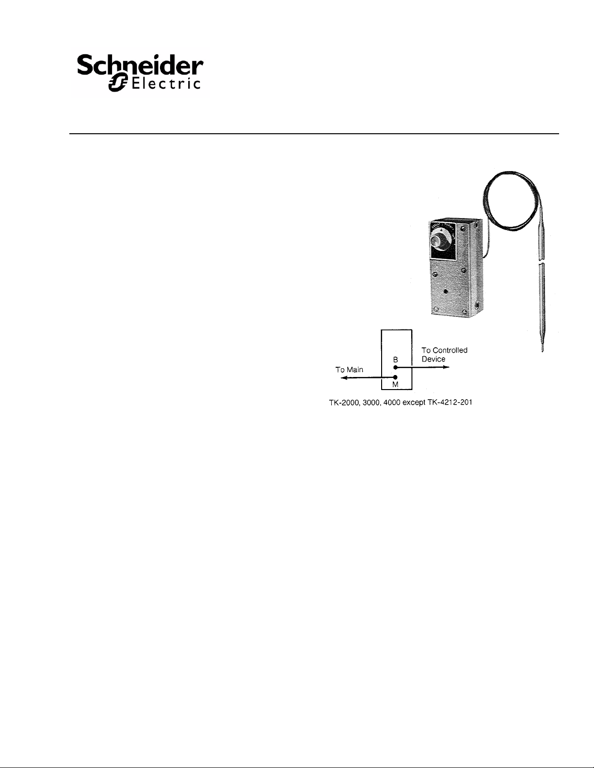
TK-2001, TK-2012, TK-2201,
TK-3001, TK-3201, TK-4001,
TK-4012, TK-4212 TK-4212-201
Pneumatic Bulb Thermostats
General Instructions
Options
None
ACCESSORIES
AT-208 Duct mounting kit
Tool-95 Pneumatic calibration tool kit
Printed in U.S.A. 12/09 © Copyright 2009 Schneider Electric All Rights Reserved. F-12585-8
Page 2
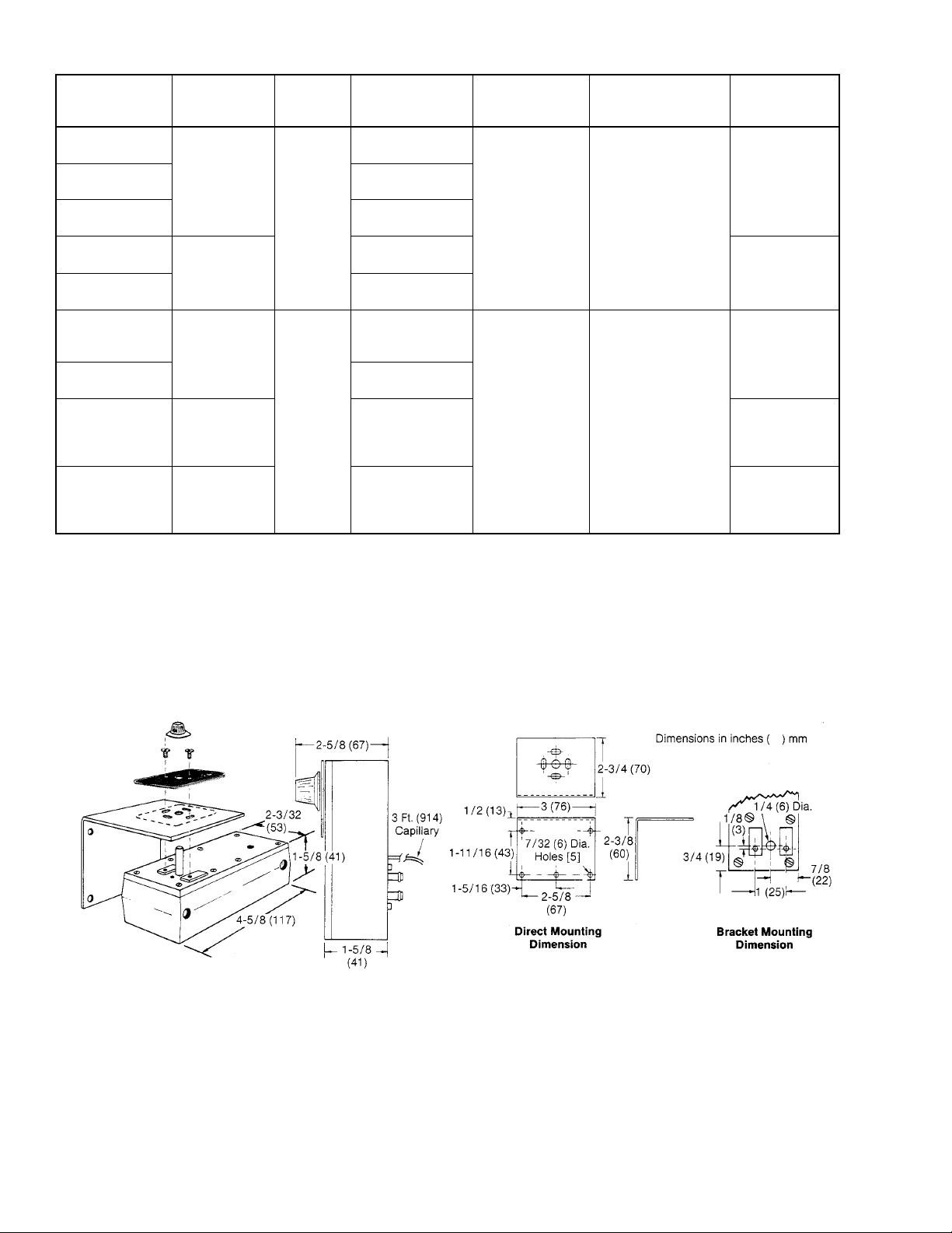
Table-1 Model Chart.
Bulb Style
Dimensions in
inches (mm)
Straight
7/32 x 14 (6 x 356)
Coiled
1 x 5 (25 x 127)
Averaging
1/8 x 48 (3 x 1.2 m)
Straight
7/32 x 14 (6 x 356)
Coiled
1 x 5 (25 x 127)
Straight
3/16 x 11-1/4 (5 x
286)
Averaging
3/32 x 54 (2 x 1.4 m)
Averaging
3/32 x 54 (2 x 1.4 m)
Averaging
3/32 x 54 (2 x 1.4 m)
Part
Number
Description and
Action
a
Max. Safe
Bulb Temp.
°F (°C)
TK-2001
Heating
b
DA
TK-4001
TK-2201
Heating-Cooling
140 (60)
20 (138) DA
TK-3201
TK-2012
15 (103) RA
Heating
b
DA
TK-4012
TK-4212
Heating-Cooling
20 (138) DA
230 (110)
15 (103) RA
TK-4212-201
Heating-Cooling
Low Limit
20 (138) DA Full
c
Output 15 (103)
a
Direct Acting (DA) - Increase output pressure on temp. rise.
Reverse Acting (RA) - Decrease output pressure on temp. rise.
b
Field changeable to reverse acting.
c
AT 20 psi (138 kPa) unit can bleed down a branch line from a controlling thermostat.
At 15 psi (103 kPa) unit is inoperative, i.e. passes controlling thermostat signal.
Control Dial
Range
°F (°C)
Dial Marked
Cooler-Warmer
60-90
(15-32)
Dial Marked
Cooler-Warmer
30-90 (-1 to 32)
Throttling Range
Adjustable 2-10°F
(1-6
°C)/10 psi (69 kPa)
Factory Set
4°F (2°C)/
10 psi (69 kPa)
Adjustable 5-25°F
(3-14
°C)/
10 psi (69 kPa) Factory
Set
10°F (6°C)/
10 psi (69 kPa)
Supply Air
Pressure psig
(kPa)
15 (103)TK-3001
15 (103) RA
Cooling
20 (138) DA
a
a
Heating
15 (103)
15 (103) RA
Cooling
20 (138) DA
a
a
Heating
15 (103
Full Output
20 (138) DA
a
Heating
DIMENSIONS
Figure-1 Mounting Dimensions.
2 © Copyright 2009 Schneider Electric All Rights Reserved. F-12585-8
Page 3
INSTALLATION
Locating
The thermostat can be mounted in any position. However, it is
most common to mount the thermostat with the setpoint
adjusting shaft on top. The adjusting mechanism is in the
thermostat on the side opposite from the setpoint knob shaft.
This area should be readily accessible so that the thermostat
can be serviced easily. Locate the bulb in the return air intake
in a position where it will sense representative air
temperatures.
Mounting
If the thermostat is mounted directly to the unit air conditioner,
drill three holes corresponding to the location of the mounting
holes and setpoint shaft in the thermostat. T o use bracket, drill
three holes to match any three of the five bracket mounting
holes selected (Figure 1).
Mount the thermostat using the two #10-32 screws, and the
scale plate which indicates the temperature setting. Attach the
knob, positioned so that the pointer indicates the cooler
(CCW) position on the scale. Rotate setpoint to midscale.
Uncoil the capillary tubing and fasten the bulb in the air stream
being controlled as shown in Figures 2 and 3 below. (See
Figures 7 and 8 for duct mounting template and assembly).
Attach 1/4" O.D. plastic tube to “m” (main) and “B” (branch)
fittings by slightly rotating the tubes back and forth and
pushing firmly onto the fitting (see Figure 4).
CONVERSION OF DIRECT ACTING THERMOSTAT TO REVERSE ACTING
1. Remove direct acting calibration screw complete with tension nut (Figure 4).
2. Insert screw into threaded hole where reverse acting screw is shown in Figure 4.
3. Tighten tension nut carefully until it is snug.
Caution: DO NOT overtighten as this will ruin nut.
4. Calibrate per instructions shown below.
Figure-2 Mounting TK-2000 Series Bulb.
Figure-3 Mounting TK-4000 Series Bulb.
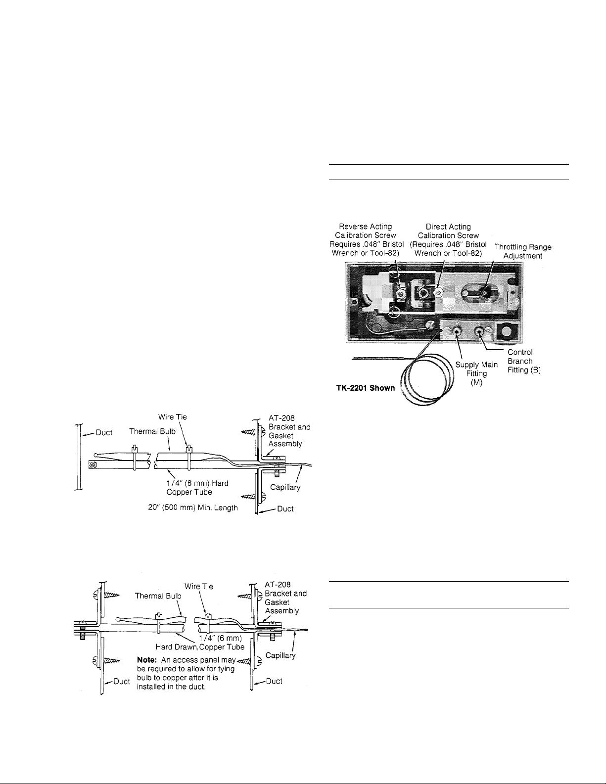
Figure-4
THROTTLING RANGE ADJUSTMENT
The throttling range should be set at the lowest value which
will allow the thermostat to control the system without cycling
under normal load conditions. The most satisfactory setting
will vary with the type of control system.
The throttling range is changed by sliding the throttling range
adjustment pivot in the flapper to its proper position (see
Figure 4). Calibration of the thermostat should be checked
after the throttling range has been changed. When making the
throttling range adjustment, care should be taken to prevent
excessive side forces on the flapper lever (see Figure 6).
Caution: In no case should the pivot point be rais ed when
the adjustment is made (see Figure 6).
CALIBRATION
After the throttling range adjustment is made, the thermostat
should be checked for calibration. As a nominal calibration,
the controlled branch pressure should be 8 psig (55 kPa)
when the setpoint is equal to the bulb temperature, indicated
by a thermometer located near the bulb. In some applications,
a value other than 8 psig (55 kPa) will be required to get the
desired control results. Change the 8 psig (55 kPa)
designation as used in the calibration procedure, should this
be the case.
F-12585-8 © Copyright 2009 Schneider Electric All Rights Reserved. 3
Page 4
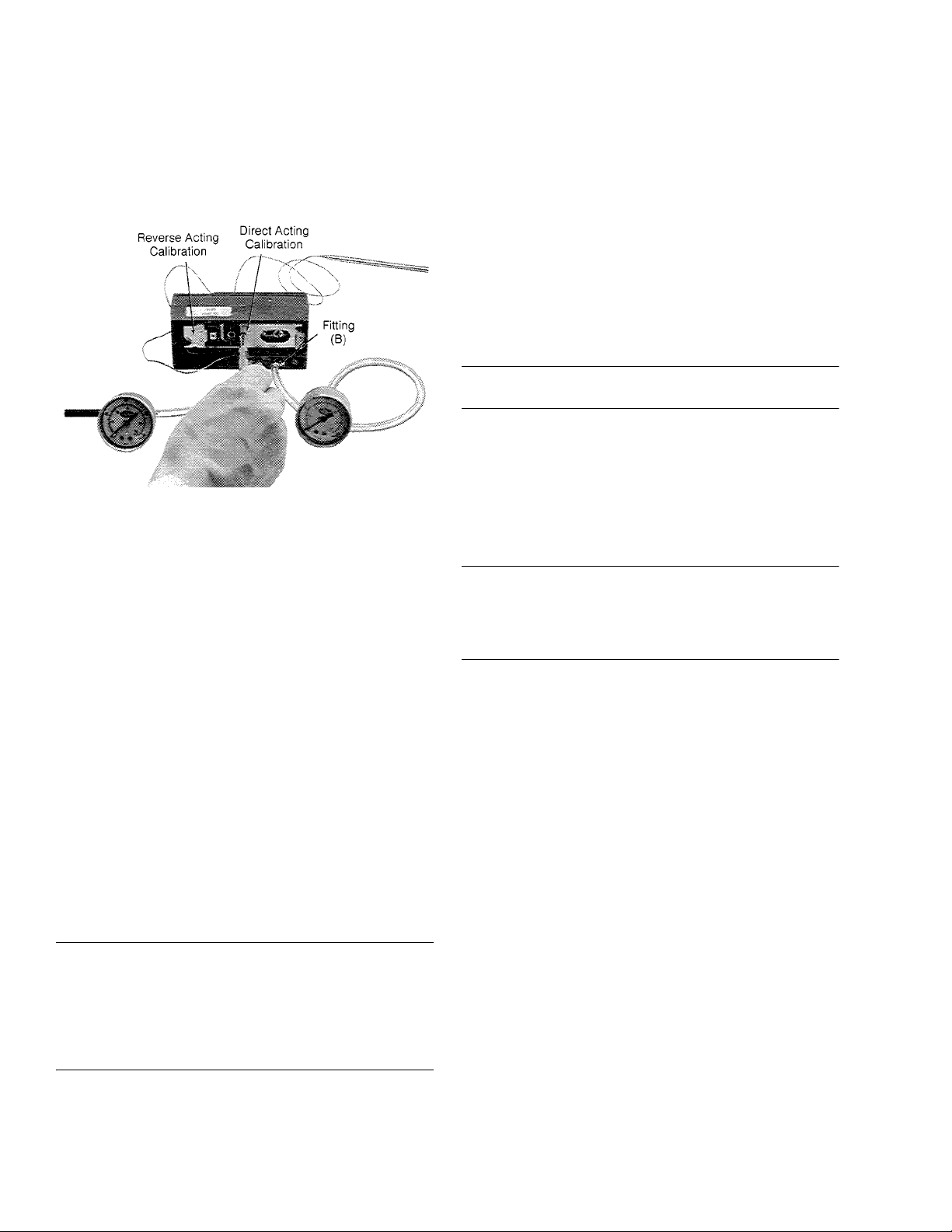
Calibrate the thermostat as follows (See Figure 5):
Disconnect the branch line at the thermostat and attach a test
gauge to the fitting (B). Push the tubing on as far as it will go,
approximately 1/4" (6 mm). The tubing for this test gauge
should be approximately 6" (150 mm) long to permit bringing
the gauge out from the test point to a place where it can be
easily read. The supply pressure to the thermostat should be
15 psig (103 kPa).
Figure-5
One Temperature Thermostats
These thermostats are factory adjusted to operate at the
midpoint of the dial span, when the adjusting dial is in its
mid-position. Whenever the throttling range is changed, the
thermostat calibration should be checked and adjusted if
necessary as follows:
1. The scale on the thermostat represents 30°F (17°C) or 60°F (33°C) span (see page 1) with the desired control point in the center. Each divi sion is equal to 5 °F (3°C) for 30°F (17°C) span units and 10°F (6°C) for 60°F (33°C) span units.
2. Observe the temperature of the bulb using a test thermometer. T urn the knob of the thermostat to the point on the scale which would correspond to the bulb temperature. Read the branch line pressure. It should be 8 psig ±1 psig (55 kPa ±7 kPa).
3. If the pressure is not 8 psig (55 kPa) use a .048" Bristol
wrench (TOOL-82) in the calibrating screw and adjust the
screw to obtain 8 psig (55 kPa). The proper screw holes
for the reverse acting or direct acting calibration are
labeled on the main lever (Figure 5).
Caution: Cae should be taken when adjusting the reverse
acting setpoint screw. Avoid unnecessary side motions and
particularly avoid lifting the lever to which the screw is
attached. Burrs on the Bristol wr ench could cause it to stick in
the screw. Note also, that the hex nuts on the adjusting
screws are used to provide tension only and should not be
loosened when making calibration adjustments.
4. When the calibration has been completed, turn the knob to the desired setpoint and remove the gauge, reconnect the branch line and replace the cover.
Heating-Cooling Thermostats
1. Adjust the supply line pressure for the system to 25 psig (172 kPa).
2. Connect a pressure regulator into the supply main between the main and the thermostat at the thermostat location.
3. Adjust the regulator to 20 psig (138 kPa); at this supply pressure the thermostat is direct acting.
4. Set the dial knob on the thermostat to the bulb temperature setting and observe the branch line control air pressure. This pressure should be 8 psig ±1 psi (55 kPa ±7 kPa).
5. If not, adjust the direct acting screw to obtain 8 psig (55 kPa) branch line control pressure using a .048" Bristol wrench (Tool-82).
Caution: Do not loosen the hex nut on the screw.This nut is
for friction purposes only; it does not lock the screw.
6. Adjust the regulator in the main line to 15 psig (103 kPa). At this supply pressure the temperature is reverse acting.
7. Observe the branch line control air pressure. If this pressure is not 8 psig (55 kPa), use a .048" Bristol wrench (TOOL-82) and adjust the reverse acting calibrating screw to obtain an 8 psig (55 kPa) branch line control pressure.
Caution: The lever to which this screw is attached contains
a spring hinge and is pivoted on the switch point adjusting
spring. Undue side motion or forces tending to lift the switch
lever off the main lever can damage the hinge or unseal the
lever.
8. Recheck calibration by switching the supply pressure between 15 and 20 psig (103 and 138 kPa) several times and observe the control pressure. If it varies from the desired pressure, repeat the calibration procedures.
9. Calibration is now complete. Turn the adjusting knob to the desired setpoint. Remove the test gauge and regulator, reconnect the main and branch lines and replace the cover.
Heating-Cooling Low Limit TK-4212-201
A special Heating-Cooling Thermostat is available for unitary
heating-cooling applications. This thermostat is very similar to
the TK-4212 except:
1. The restriction plate has been removed making the unit a one pipe thermostat. The air signal to the main connection actuates only the switchover parts.
2. The R.A. calibration screw has been removed. Therefore, when the main pressure is reduced to 15 psig (103 kPa). there is no calibration screw to contact the main lever and the flapper closes the nozzle completely and the thermostat is inoperative.
To calibrate apply 20 psig (138 kPa) to the main and full
branch pressure from the primary controller to the branch
connection of the TK-4212-201. Then calibrate as a single
temperature D.A. thermostat.
4 © Copyright 2009 Schneider Electric All Rights Reserved. F-12585-8
Page 5

MAINTENANCE
This is a quality product. Regular maintenance of the total
system is recommended to assure sustained optimum
performance.
FIELD REPAIR
Repair is not recommended except for replacement of
restrictor assembly. Use AT -529 restrictor kit (see Figure 6) if
restrictor replacement is required. Otherwise, replace
thermostats if system is not operating correctly and the cause
is traced to the thermostat.
Figure-7 AT-208 Duct Mounting Kit.
Figure-6
Figure-8 Bulb Mounting Hole Arrangement for Drilling
Ductwork.
F-12585-8 © Copyright 2009 Schneider Electric All Rights Reserved. 5
Page 6
On Oc tober 1st, 2009, TAC becam e the Buildings busin ess of its par ent company Schneider El ectric. This docum ent ref lects the visual i denti ty of Schneider Electric,
ho wever t he re remains refer ences to TAC as a corpor a te br an d in the body copy. As eac h document i s updated, the body copy will be changed to reflect appr op riate
corpor ate br a nd ch a nges.
Copyright 2009, Schneider Electric
All brand names, trademarks and registered
trademarks are the property of their respective
owners. Information contained within this
document is subject to change without notice.
F-12585-8
 Loading...