

Page 1

Harmony STM6
User Manual
EIO0000004129_01
12/2020
www.se.com
Page 2

Legal Information
The Schneider Electric brand and any trademarks of Schneider Electric SE and its
subsidiaries referred to in this guide are the property of Schneider Electric SE or its
subsidiaries. All other brands may be trademarks of their respective owners.
This guide and its content are protected under applicable copyright laws and
furnished for informational use only. No part of this guide may be reproduced or
transmitted in any form or by any means (electronic, mechanical, photocopying,
recording, or otherwise), for any purpose, without the prior written permission of
Schneider Electric.
Schneider Electric does not grant any right or license for commercial use of the guide
or its content, except for a non-exclusive and personal license to consult it on an "as
is" basis. Schneider Electric products and equipment should be installed, operated,
serviced, and maintained only by qualified personnel.
As standards, specifications, and designs change from time to time, information
contained in this guide may be subject to change without notice.
To the extent permitted by applicable law, no responsibility or liability is assumed by
Schneider Electric and its subsidiaries for any errors or omissions in the informational
content of this material or consequences arising out of or resulting from the use of the
information contained herein.
Page 3

Table of Contents
Safety Information ......................................................................................5
About This Manual......................................................................................6
Overview ................................................................................................. 11
Device Connectivity .................................................................................. 17
Parts Identification and Functions .............................................................. 20
Specifications........................................................................................... 22
Dimensions..............................................................................................30
Installing and Wiring ................................................................................. 37
Document Scope ..................................................................................6
Validity Note .........................................................................................6
Registered Trademarks.........................................................................6
Related Documents ..............................................................................6
Product Related Information ..................................................................6
Part Numbers ..................................................................................... 11
Package Contents .............................................................................. 11
Certifications and Standards ................................................................12
Federal Communication Commission Radio Frequency Interference
Statement - For USA ........................................................................... 14
Hazardous Location Installation - For USA and Canada ......................... 14
System Design ...................................................................................17
Accessories........................................................................................ 17
Parts Identification ..............................................................................20
LED Indications .................................................................................. 21
General Specifications ........................................................................ 22
Electrical Specifications ................................................................. 22
Environmental Specifications .........................................................22
Structural Specifications ................................................................23
Functional Specifications.....................................................................25
Display Specifications.................................................................... 25
Touch Panel.................................................................................. 25
Memory........................................................................................ 25
Clock............................................................................................ 25
Interface Specifications ....................................................................... 27
Specifications of Each Interface ..................................................... 27
Interface Connection .....................................................................27
Serial Interface.............................................................................. 28
HMISTM6200 External Dimensions...................................................... 30
HMISTM6400 External Dimensions...................................................... 32
HMISTM6BOX External Dimensions .................................................... 34
Rear Module Installation Adapter External Dimensions .......................... 35
Display Module/Rear Module Separation Cable Dimensions ..................36
Installation..........................................................................................37
Precautions for Building into an End-use Product............................. 37
Installation Requirements ..............................................................37
Panel Cut Dimensions ...................................................................39
Installation Procedure.................................................................... 40
Removal Procedure....................................................................... 42
Separate Installation ...........................................................................44
EIO0000004129_00 3
Page 4

Introduction ..................................................................................44
Precautions for Building into an End-use Product............................. 44
Installation Requirements for Separate Installation...........................44
Installation Procedure on DIN Rail and Panel ..................................46
Removal Procedure from DIN Rail and Panel .................................. 48
HMISTM6BOX Installation...................................................................50
Precautions for Installing to an End-use Product ..............................50
Installation Requirements for HMISTM6BOX................................... 50
Installation Procedure on DIN Rail ..................................................51
Removal Procedure from DIN Rail .................................................. 53
Wiring the Power Supply ..................................................................... 53
DC Power Cord Preparation........................................................... 53
How to Connect the DC Power Cord ............................................... 54
Power Supply Precautions .............................................................55
Grounding ....................................................................................57
USB Cable Clamp ............................................................................... 58
Attaching USB Clamp Type A......................................................... 58
Removing USB Clamp Type A........................................................60
Attaching USB Clamp mini-B..........................................................60
Removing USB Clamp mini-B ........................................................61
Maintenance ............................................................................................ 62
Regular Cleaning ................................................................................ 62
Periodic Check Points .........................................................................62
Replacing the Installation Gasket ......................................................... 63
Replacing the Battery .......................................................................... 63
Replacing the Backlight .......................................................................63
4 EIO0000004129_00
Page 5
Safety Information
Safety Information
Important Information
Read these instructions carefully and look at the equipment to become familiar
with the device before trying to install, operate, service or maintain it. The
following special messages may appear throughout this bulletin or on the
equipment to warn of potential hazards or to call attention to information that
clarifies or simplifies a procedure.
The addition of this symbol to a “Danger” or “Warning” safety label indicates that
an electrical hazard exists which will result in personal injury if the instructions
are not followed.
This is the safety alert symbol. It is used to alert you to potential personal injury
hazards. Obey all safety messages that follow this symbol to avoid possible injury
or death.
DANGER
DANGER indicates a hazardous situation which, if not avoided, will result in
death or serious injury.
Failure to follow these instructions will result in death or serious injury.
WARNING
WARNING indicates a hazardous situation which, if not avoided, could result
in death or serious injury.
Failure to follow these instructions can result in death, serious injury, or
equipment damage.
CAUTION
CAUTION indicates a hazardous situation which, if not avoided, could result in
minor or moderate injury.
Failure to follow these instructions can result in injury or equipment
damage.
NOTICE
NOTICE is used to address practices not related to physical injury.
Failure to follow these instructions can result in equipment damage.
Please Note
Electrical equipment should be installed, operated, serviced and maintained only
by qualified personnel. No responsibility is assumed by Schneider Electric for any
consequences arising out of the use of this material. A qualified person is one who
has skills and knowledge related to the construction, installation, and operation of
electrical equipment and has received safety training to recognize and avoid the
hazards involved.
EIO0000004129_00 5
Page 6

About This Manual
Document Scope
This manual describes how to use this product.
Validity Note
This documentation is valid for this product.
The technical characteristics of the devices described in the present document
also appear online. To access the information online, go to the Schneider Electric
home page.
www.se.com
The characteristics presented in the present document should be the same as
those that appear online. In line with our policy of constant improvement we may
revise content over time to improve clarity and accuracy. In the event that you see
a difference between the document and online information, use the online
information as your reference.
About This Manual
Registered Trademarks
Microsoft®and Windows®are registered trademarks of Microsoft Corporation in
the United States and/or other countries.
Product names used in this manual may be the registered trademarks owned by
the respective proprietors.
Related Documents
You can download the manuals related to this product, such as the software
manual, from our website.
www.se.com
Product Related Information
If the equipment is used in a manner not specified by the manufacturer, the
protection provided by the equipment may be impaired.
6 EIO0000004129_00
Page 7
About This Manual
DANGER
HAZARD OF ELECTRIC SHOCK, EXPLOSION, OR ARC FLASH
• Remove all power from the device before removing any covers or elements
of the system, and prior to installing or removing any accessories, hardware,
or cables.
• Unplug the power cable from both this product and the power supply prior to
installing or removing the product.
• Always use a properly rated voltage sensing device to confirm power is off
where and when indicated.
• Replace and secure all covers or elements of the system before applying
power to this product.
• Use only the specified voltage when operating this product. This product is
designed to use 24 Vdc. Always check whether your device is DC powered
before applying power.
Failure to follow these instructions will result in death or serious injury.
Critical alarm indicators and system functions require independent and redundant
protection hardware and/or mechanical interlocks.
When you cycle power, wait at least 10 seconds after it has been turned off. If this
product is restarted too quickly, it may not operate correctly.
In the event the screen cannot be properly read, for example, if the backlight is not
functioning, it may be difficult or impossible to identify a function. Functions that
may present a hazard if not immediately executed, such as a fuel shut-off, must be
provided independently of this product. The machine’s control system design must
take into account the possibility of the backlight no longer functioning and the
operator being unable to control the machine or making mistakes in the control of
the machine.
WARNING
LOSS OF CONTROL
• The designer of any control scheme must consider the potential failure
modes of control paths and, for certain critical control functions, provide a
means to achieve a safe state during and after a path failure. Examples of
critical control functions are emergency stop and overtravel stop, power
outage and restart.
• Separate or redundant control paths must be provided for critical control
functions.
• System control paths may include communication links. Consideration must
be given to the implications of unanticipated transmission delays or failures
of the link.
• Observe all accident prevention regulations and local safety guidelines.
• Each implementation of this product must be individually and thoroughly
tested for proper operation before being placed into service.
• The machine control system design must take into account the possibility of
the backlight no longer functioning and the operator being unable to control
the machine, or making errors in the control of the machine.
Failure to follow these instructions can result in death, serious injury, or
equipment damage.
For additional information, refer to NEMA ICS 1.1 (latest edition), "Safety
Guidelines for the Application, Installation, and Maintenance of Solid State
Control" and to NEMA ICS 7.1 (latest edition), "Safety Standards for Construction
and Guide for Selection, Installation and Operation of Adjustable-Speed Drive
Systems" or their equivalent governing your particular location.
EIO0000004129_00 7
Page 8
About This Manual
WARNING
UNINTENDED EQUIPMENT OPERATION
• The application of this product requires expertise in the design and
programming of control systems. Only persons with such expertise should
be allowed to program, install, alter, and apply this product.
• Follow all local and national safety standards.
Failure to follow these instructions can result in death, serious injury, or
equipment damage.
WARNING
UNINTENDED EQUIPMENT OPERATION
• Do not use this product as the only means of control for critical system
functions such as motor start/stop or power control.
• Do not use this equipment as the only notification device for critical alarms,
such as device overheating or overcurrent.
• Use only the software provided with this product. If you use other software,
please confirm the operation and safety before use.
Failure to follow these instructions can result in death, serious injury, or
equipment damage.
The following characteristics are specific to the LCD panel and are considered
normal behavior:
• LCD screen may show unevenness in the brightness of certain images or
may appear different when seen from outside the specified viewing angle.
Extended shadows, or crosstalk may also appear on the sides of screen
images.
• LCD screen pixels may contain black and white colored spots and color
display may seem to have changed.
• When experiencing vibrations within a certain frequency range and vibration
acceleration is above what is acceptable, the LCD screen may partially turn
white. Once the vibration condition ends, the whitening of the screen is
resolved.
• When the same image is displayed on the screen for a long period, an
afterimage may appear when the image is changed.
• The panel brightness may decrease when used for a long time in an
environment continuously filled with inert gas. To prevent deterioration of
panel brightness, regularly ventilate the panel. For more information, please
contact your local distributor.
www.se.com
NOTE: Change the screen image periodically and try not to display the same
image for a long period of time.
8 EIO0000004129_00
Page 9
About This Manual
SERIOUS EYE AND SKIN INJURY
The liquid in the LCD panel contains an irritant:
• Avoid direct skin contact with the liquid.
• Wear gloves when you handle a broken or leaking unit.
• Do not use sharp objects or tools in the vicinity of the LCD panel.
• Handle the LCD panel carefully to prevent puncture, bursting, or cracking of
the panel material.
• If the panel is damaged and any liquid comes in contact with your skin,
immediately rinse the area with running water for at least 15 minutes. If the
liquid gets in your eyes, immediately rinse your eyes with running water for at
least 15 minutes and consult a doctor.
Failure to follow these instructions can result in death, serious injury, or
equipment damage.
Cybersecurity Best Practices
To help keep your Schneider Electric products secure and protected, we
recommend that you implement the cybersecurity best practices. Following the
recommendations may help significantly reduce your company’s cybersecurity
risk. For the recommendations, refer to the following URL:
https://www.se.com/en/download/document/7EN52-0390/
WARNING
EIO0000004129_00 9
Page 10

Page 11
Overview
A
B C D E
Overview
Part Numbers
Part Number List
What’s in This Chapter
Part Numbers................................................................................................ 11
Package Contents......................................................................................... 11
Certifications and Standards ..........................................................................12
Federal Communication Commission Radio Frequency Interference
Statement - For USA ..................................................................................... 14
Hazardous Location Installation - For USA and Canada ...................................14
Series Part name Part number
Harmony STM6 HMISTM6200 HMISTM6200
HMISTM6400 HMISTM6400
HMISTM6BOX HMISTM6BOX
Part Number Configuration
The following describes the configuration of model numbers.
Digit position
1 2 3 4 5 6 7 8 9 10
H M I (model) (series) (display size) (type)
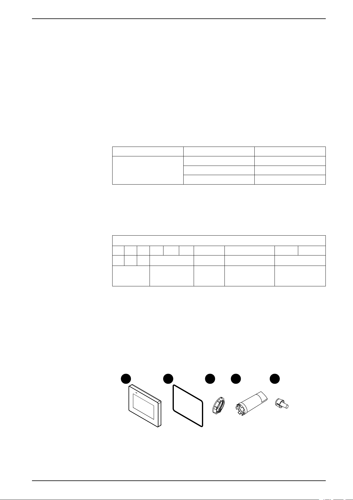
Package Contents
Verify all items listed here are present in your package.
Display module
NOTE: All part numbers may be followed by any letter or number.
STM 6 2: 4"
4: 7"
B: No display
NOTE: This product has been carefully packed with special attention to
quality. However, should you find anything damaged or missing, please
contact your local distributor immediately.
00: (Standard)
EIO0000004129_00 11
Page 12
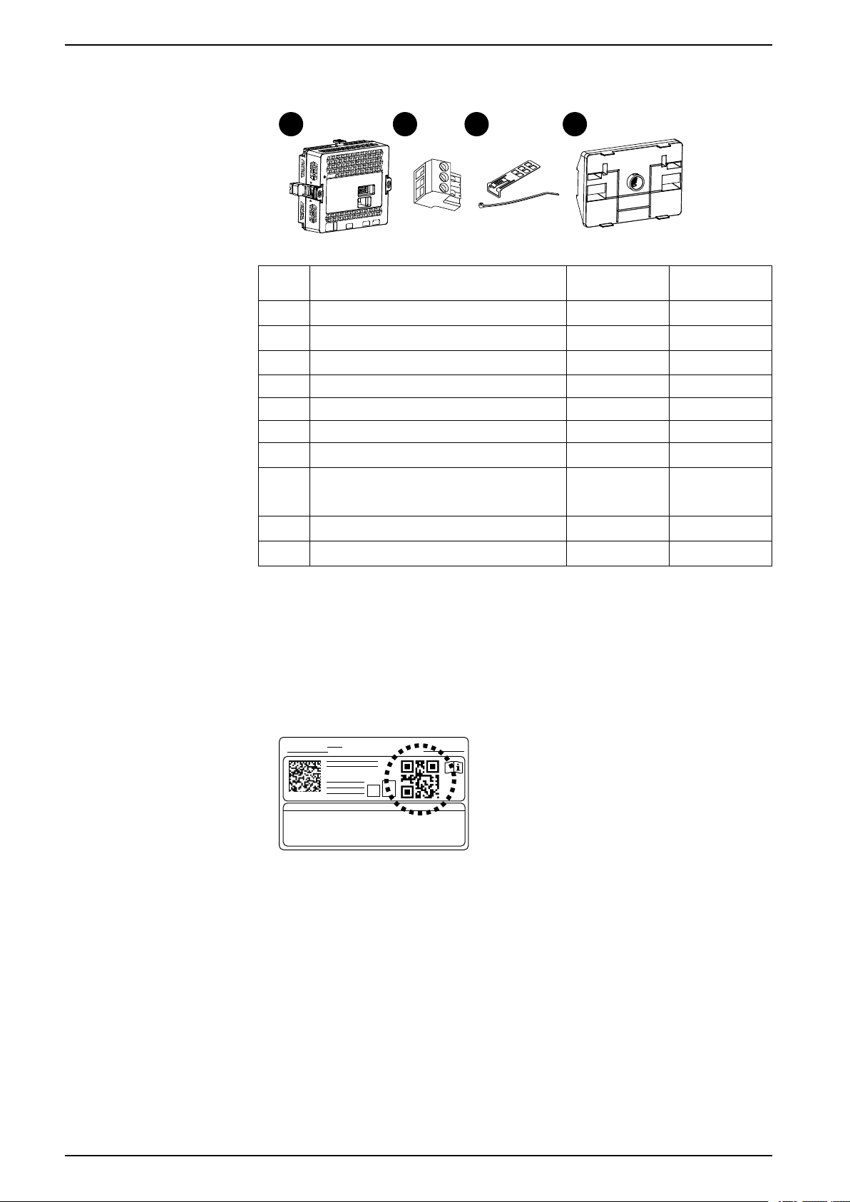
Rear module
F G H I
PV:___ RL:___ SV:___
HMISTM6
Overview
Item HMISTM6200/
A Display module 1
B Installation gasket (attached to this product) 1
C Display module fixing nut 1
D Socket wrench 1
E Anti-rotation tee 1
F Rear module 1 1
G DC power connector 1 1
H USB cable clamp (Type A)
(1 set = clip: 1, tie: 1)
I Rear module installation adapter
J Quick reference guide 1 1
Product Revision and QR Code for Manual
You can identify the product version (PV), revision level (RL), and the software
version (SV) from the product label.
You can also check the contents of this manual by using the QR code on the
product label. Confirm the location of the QR code below and refer to the manual.
HMISTM6400
1 1
-
HMISTM6BOX
-
-
-
-
-
1
Certifications and Standards
The certifications and standards listed below may include those that are not yet
acquired. Please check the product marking and the following URL for the latest
acquisition status.
www.se.com
Agency Certifications
12 EIO0000004129_00
• Underwriters Laboratories Inc., UL 61010-2-201 and CSA C22.2
N°61010-2-201, for Industrial Control Equipment used in Ordinary Location
Page 13

Overview
Compliance Standards
• Underwriters Laboratories Inc., UL 121201 and CSA C22.2 N°213, for
Industrial Control Equipment used in Class I, Division 2 Hazardous
(Classified) Locations
• IECEx / ATEX for use in zone 2 gas /zone 22 dust
• Merchant Navy, following IACS E10.
Europe:
CE
• Directive 2014/30/EU (EMC: EN 61131-2)
• Directive 2014/34/EU (ATEX)
Australia, New Zealand:
• RCM
Korea:
• KC
Russia, Belarus, Kazakhstan:
• EAC
Hazardous Substances
End of Life (WEEE)
KC Markings
This product is designed to be compliant with the following environmental
regulations, even if the product may not fall directly in the scope of the regulation:
• RoHS, Directive 2011/65/EU and 2015/863/EU
• RoHS China, Standard GB/T 26572
• REACH regulation EC 1907/2006
The product contains electronic boards. It must be disposed of in specific
treatment channels. The product contains cells and/or storage batteries which
must be collected and processed separately when they have run out and at the
end of product life (Directive 2012/19/EU).
Refer to Maintenance, page 62 when extracting cells and batteries from the
product. These batteries do not contain a weight percentage of heavy metals over
the threshold notified by European Directive 2006/66/EC.
EIO0000004129_00 13
Page 14
Federal Communication Commission Radio Frequency Interference Statement - For USA
FCC Radio Interference Information
This product has been tested and found to comply with the Federal
Communications Commission (FCC) limits for a Class A digital device, pursuant to
Part 15 of the FCC Rules. These limits are designed to provide reasonable
protection against harmful interference in a commercial, industrial or business
environment. This product generates, uses, and can radiate radio frequency
energy and, if not installed and used in accordance with the instructions, may
cause or be subject to interference with radio communications. To minimize the
possibility of electromagnetic interference in your application, observe the
following two rules:
• Install and operate this product in such a manner that it does not radiate
sufficient electromagnetic energy to cause interference in nearby devices.
• Install and test this product to ensure that the electromagnetic energy
generated by nearby devices does not interfere with the operation of this
product.
• Changes or modifications not expressly approved by the party responsible for
compliance could void the user’s authority to operate this product.
Overview
WARNING
ELECTROMAGNETIC / RADIO INTERFERENCE
Electromagnetic radiation may disrupt the operation of this product leading to
unintended equipment operation. If electromagnetic interference is detected:
• Increase the distance between this product and the interfering equipment.
• Reorient this product and the interfering equipment.
• Reroute power and communication lines to this product and the interfering
equipment.
• Connect this product and the interfering equipment to different power
supplies.
• Always use shielded cables when connecting this product to a peripheral
device or another computer.
Failure to follow these instructions can result in death, serious injury, or
equipment damage.
Hazardous Location Installation - For USA and Canada
General
This product is suitable for use in Class I, Division 2, Groups A, B, C, and D
hazardous locations or in non-hazardous locations. Before installing or using this
product, confirm that the Hazardous Location certification appears on the product
labeling.
NOTE: Some products are not yet rated as suitable for use in hazardous
locations. Always use your product in conformance with the product labeling
and this manual.
14 EIO0000004129_00
Page 15
Overview
DANGER
HAZARD OF ELECTRIC SHOCK, EXPLOSION, OR ARC FLASH
• Remove all power from the device before removing any covers or elements
of the system, and prior to installing or removing any accessories, hardware,
or cables.
• Unplug the power cable from both this product and the power supply.
• Always use a properly rated voltage sensing device to confirm power is off.
• Replace and secure all covers or elements of the system before applying
power to this product.
• Use only the specified voltage when operating this product. This product is
designed to use 24 Vdc. Always check whether your device is DC powered
before applying power.
Failure to follow these instructions will result in death or serious injury.
WARNING
EXPLOSION HAZARD
• Do not use this product in hazardous environments or locations other than
Class I, Division 2, Groups A, B, C, and D.
• Substitution of any components may impair suitability for Class I, Division 2.
• Always confirm the UL 121201 or CSA C22.2 N°213 hazardous location
rating of your device before installing or using it in a hazardous location.
• To apply or remove the supply power from this product installed in a Class I,
Division 2 hazardous location, you must either: A) Use a switch located
outside the hazardous environment, or B) Use a switch certified for Class I,
Division 1 operation inside the hazardous area.
• Do not connect or disconnect equipment unless power has been switched off
or the area is known to be non-hazardous. This applies to all connections
including power, ground, serial, parallel, and network connections.
• Do not install any Schneider Electric or OEM components, equipment, or
accessories unless these have also been qualified as suitable for use in
Class I, Division 2, Groups A, B, C, and D locations.
• Never use unshielded/ungrounded cables in hazardous locations.
• Use only non-incendive USB devices.
• Do not attempt to install, operate, modify, maintain, service, or otherwise
alter this product except as permitted in this manual. Unpermitted actions
may impair the suitability of this product for Class I, Division 2 operation.
Failure to follow these instructions can result in death, serious injury, or
equipment damage.
Make sure that this product is properly rated for the location. If the intended
location does not presently have a Class, Division and Group rating, then users
should consult the appropriate authorities having jurisdiction in order to determine
the correct rating for that hazardous location.
Operation and Maintenance
The systems have been designed for compliance with relevant spark ignition
tests.
EIO0000004129_00 15
Page 16

Overview
WARNING
EXPLOSION HAZARD
In addition to the other instructions in this manual, observe the following rules
when installing this product in a hazardous location:
• Wire the equipment in accordance with the National Electrical Code article
501.10 (B) for Class I, Division 2 hazardous locations.
• Install this product in an enclosure suitable for the specific application.
IP65F, UL 50/50E, Type 1, Type 4X (indoor use only), Type 12 or Type 13
enclosures are recommended even when not required by regulations.
Failure to follow these instructions can result in death, serious injury, or
equipment damage.
NOTE: IP65F is not part of UL certification.
16 EIO0000004129_00
Page 17
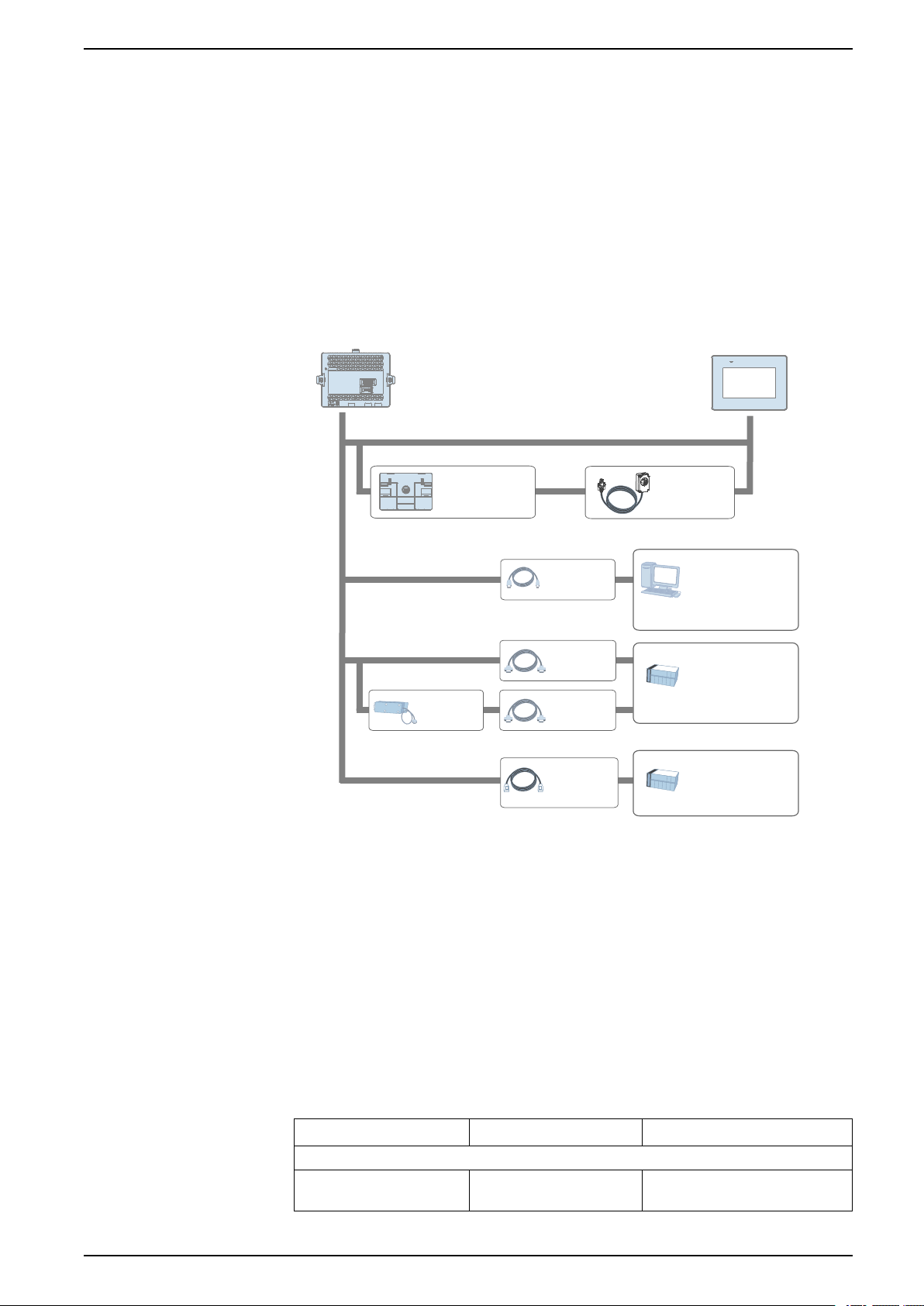
Device Connectivity
Rear Module
Installation
Adapter
*1
Display Module Interface
USB (Type A) /
USB (micro-B)
Interface
Serial Interface (COM1)
Ethernet Interface
(ETH1 / ETH2)
Cable
*1*2
Cable
*1
Cable
(commercial
type)
Host controller,
PLC*2, etc.
Personal Computer
(commercial type)
Host controller,
PLC*2, etc.
USB device
*1
USB device
(commercial type)
*3
Personal Computer
(commercial type)
Separation
Cable
*1
Cable
*1*2
Isolation
Unit
*1
Device Connectivity
What’s in This Chapter
System Design.............................................................................................. 17
Accessories .................................................................................................. 17
System Design
This section describes the system configuration with this product and peripheral
equipment.
*1
Refer to Accessories, page 17.
*2
Accessories
For information on how to connect controllers and other types of equipment,
refer to the corresponding device driver manual of your screen editing software.
*3
For supported models, contact your local Schneider Electric support
representative.
This section introduces optional products that can be used with this product.
NOTE: For host controllers and connection cables, refer to the corresponding
device driver manual of your screen editing software.
EIO0000004129_00 17
Product name Product number Description
Serial interface
RJ-45 to D-Sub 25 pin
Conversion Cable
XBTZG939 Connects a D-Sub 25-pin cable to
this product (RJ-45).
Page 18
Product name Product number Description
Device Connectivity
9-pin-to-25-pin RS-232C
Conversion Cable
COM Port Conversion
Adapter
RS-485 Isolation Unit XBTZGI485 Connects a host controller to this
USB (Type A) interface
USB Front Cable (1 m) XBTZGUSB Extension cable that attaches USB
USB (micro-B) interface
USB Transfer Cable HMIZG936 Cable for transferring screen data
USB (micro-B) Front Cable HMIZSUSBB2 Extension cable that attaches USB
Others
Rear Module Installation
Adapter
Screen Protection Sheet with
UV Protected
XBTZG919 Connects a standard RS-232C
cable (D-Sub 25-pin socket) to this
product (D-sub 9 pin plug).
XBTZGCOM1 Connects optional RS-422
communication items to serial
interface (RS-232C).
product with isolation.
interface to front panel.
from a PC (USB Type A) to this
product (USB micro-B)
interface to front panel.
HMIZM6DSA Adapter for installing the rear
module on a DIN rail.
HMIZG60W Disposable, dirt-resistant and
ultraviolet protection sheet for
4-inch Wide screen (1 sheet/set).
Maintenance Accessories
HMIZG63W Disposable, dirt-resistant and
Spacer HMIZM6MP2 Plate for adjusting installation panel
HMIZM6MP4 Plate for adjusting installation panel
Display Module/Rear Module
Separation Cable (3 m)
Display Module/Rear Module
Separation Cable (5 m)
Display Module/Rear Module
Separation Cable (10 m)
Product name Product number Description
Rear Module HMISTM6B Rear module for Harmony STM6
Display Module HMISTM62
HMIZM6RDP3 Cable for use when installing the
HMIZM6RDP5
HMIZM6RDP10
HMISTM64
ultraviolet protection sheet for
7-inch Wide screen (1 sheet/set).
thickness for the 4-inch wide
display module.
thickness for the 7-inch wide
display module.
rear module and display module
apart from the other.
Display module for HMISTM6200 ,
4-inch wide type
Display module for HMISTM6400 ,
7-inch wide type
Installation Gasket HMIZS51W2 Gasket that provides dust and
HMIZS53W2 Gasket that provides dust and
DC Power Supply Connector XBTZGPWS1 Connector for a DC power supply
USB Clamp Type A
(for 1 port)
HMIZGCLP1 Clamp to prevent disconnection of
moisture resistance, for a 4-inch
wide display module (1 piece).
moisture resistance, for a 7-inch
wide display module (1 piece).
cable.
USB cable (for 1 port, USB Type A,
5 pieces/set)
18 EIO0000004129_00
Page 19

Device Connectivity
Product name Product number Description
Display Module Fixing Nut ZB5AZ901
Nut to install the display module
(10 pieces/set)
Socket Wrench ZB5AZ905 Socket wrench to tighten and
Accessories Kit HMIZM6KIT
*1
USB Clamp mini-B can be used for optional USB micro-B cables.
loosen the display installation nut
Anti-rotation Tee, USB Clamp
Type A, USB Clamp mini-B
(1 piece/each)
*1
EIO0000004129_00 19
Page 20
Parts Identification and Functions
A
A
B
C
D
E
F G
H
What’s in This Chapter
Parts Identification.........................................................................................20
LED Indications............................................................................................. 21
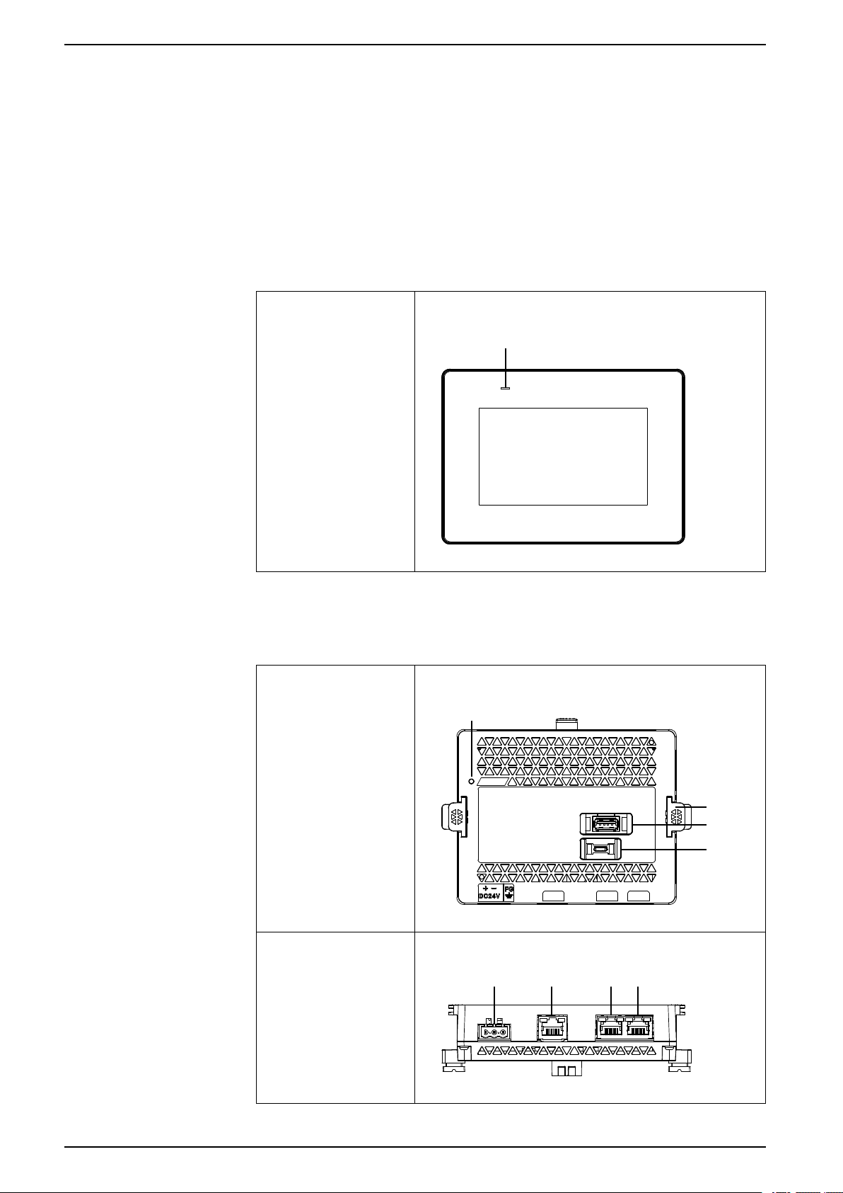
Parts Identification
Parts Identification (Display Module)
Front
Parts Identification and Functions
A. Status LED
Parts Identification (Rear Module)
Front
Bottom
20 EIO0000004129_00
Page 21
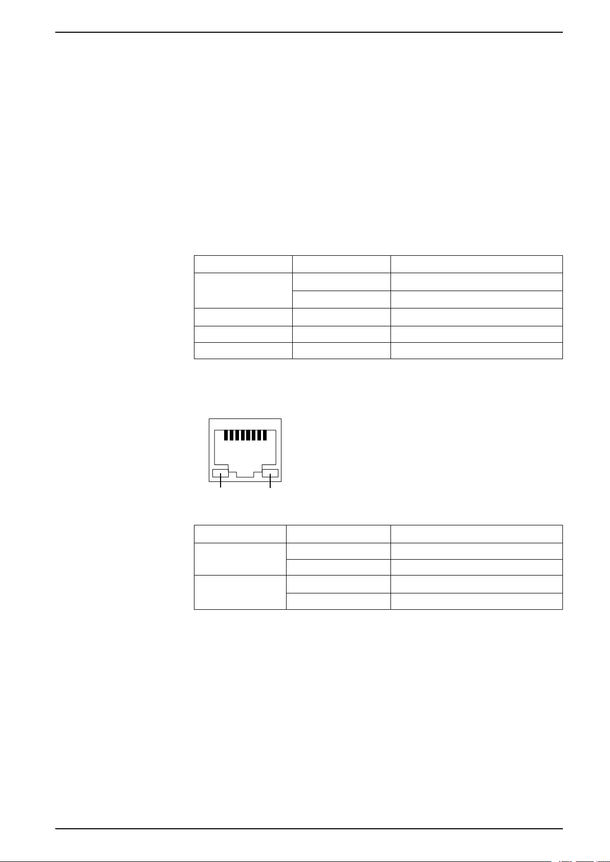
Parts Identification and Functions
Link Active
LED Indications
Status LED
A. Status LED
B. Bumper
C. USB (Type A) interface
D. USB (micro-B) interface
E. Power plug connector
F. Serial interface (COM1)
G. Ethernet interface (ETH1)
H. Ethernet interface (ETH2)
Color Indicator HMI operation
Green ON In operation
LED fade Backlight OFF (Standby Mode)
Orange Flashing Software starting up
Ethernet LED
Red ON Power is ON.
-
Color Indicator Description
Green (Link) ON Data transmission is available.
Green (Active) Flashing Data transmission is occurring.
OFF Power is OFF.
OFF No connection or error
OFF No data transmission
EIO0000004129_00 21
Page 22

Specifications
What’s in This Chapter
General Specifications................................................................................... 22
Functional Specifications ...............................................................................25
Interface Specifications..................................................................................27
General Specifications
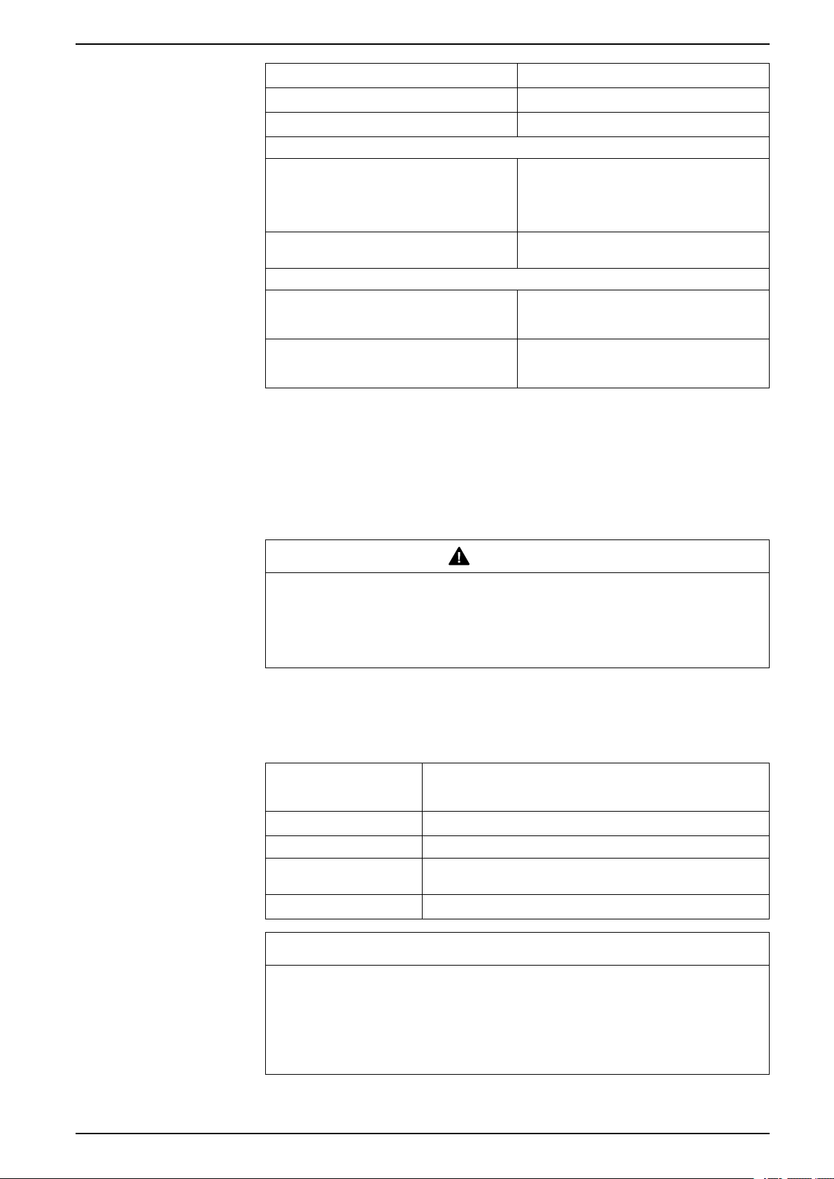
Electrical Specifications
Rear Module
Rated input voltage 24 Vdc
Input voltage limits 19.2...28.8 Vdc
Voltage drop (at rated input voltage) 5 ms or less
Specifications
Power
consumption
In-rush current 30 A or less
Noise immunity Noise voltage: 1,000 Vp-p
Dielectric strength 1,000 Vac for 1 minute (between power terminal and FG
Insulation resistance 500 Vdc, 10 MΩ or more (between power terminal and FG
Max 6.8 W
When power is not
supplied to
external devices
3.5 W
Pulse duration: 1 μs
Rise time: 1 ns (via noise simulator)
terminal)
terminals)
Display Module
Specification HMISTM6200 HMISTM6400
Power consumption Max 1.0 W 3.6 W
When screen turns off
the backlight (standby
mode)
NOTE: The power consumption for the combined unit of the rear module and
the display module equals the sum of power consumption of the two modules.
0.6 W 1.3 W
Environmental Specifications
Use and store this product in areas that conform to the specified conditions.
NOTE: When using any of the options for this product, check the
specifications for special conditions or cautions that may apply to this product.
Physical environment
Ambient air temperature 0...50 °C (32...122 °F)
Storage temperature -20...60 °C (-4...140 °F)
Ambient air and storage humidity
Dust 0.1 mg/m
22 EIO0000004129_00
(For rear module only: 0...60 °C [32...140 °F])
10...90% RH (non condensing, wet bulb
temperature 39 °C [102.2 °F] or less)
3
levels)
(10-7oz/ft3) or less (non-conductive
Page 23
Specifications
Pollution degree For use in Pollution Degree 2 environment
Corrosive gases Free of corrosive gases
Atmospheric pressure (operating altitude) 800...1,114 hPa (2,000 m [6,561 ft] or lower)
Mechanical environment
Vibration resistance IEC/EN 61131-2 compliant
5...9 Hz Single amplitude 3.5 mm (0.14 in)
9...150 Hz Fixed acceleration: 9.8 m/s
X, Y, Z directions for 10 cycles (approximately
100 minutes)
2
Shock resistance IEC/EN 61131-2 compliant
Electrical environment
Electrical fast transient/burst immunity IEC 61000-4-4
Electrostatic discharge immunity Contact discharge method: 6 kV
2
147 m/s
2 kV: Power port
1 kV: Signal ports
Air discharge method: 8 kV
(IEC/EN 61000-4-2 Level 3)
, X, Y, Z directions for 3 times
Air Quality Requirements
Do not operate or store the product where chemicals evaporate, or where
chemicals are present in the air:
• Corrosive chemicals: Acids, alkalines, liquids containing salt.
• Flammable chemicals: Organic solvents.
CAUTION
INOPERATIVE EQUIPMENT
Do not allow water, liquids, metal, and wiring fragments to enter the panel case.
Failure to follow these instructions can result in injury or equipment
damage.
Structural Specifications
Rear Module
Grounding
Cooling method Natural air circulation
Structure IP20
External dimensions
(W x H x D)
Weight 0.27 kg (0.6 lb) or less
Functional grounding: Grounding resistance of 100 Ω or less, 2 mm
(AWG 14) or thicker wire, or your country's applicable standard (SG
and FG are connected inside the product).
145.6 x 108.23 x 41.4 mm (5.73 x 4.26 x 1.63 in) (excluding
protrusions)
NOTICE
EQUIPMENT DAMAGE
• Store this product in areas where temperatures are within the product’s
specifications.
• Do not restrict or block the product’s ventilation slots.
Failure to follow these instructions can result in equipment damage.
2
EIO0000004129_00 23
Page 24

Specifications
Display Module
HMISTM6200 HMISTM6400
Cooling method Natural air circulation
Structure
External dimensions
(W x H x D)
Panel cut dimensions Diameter 22.5 mm (0.88 in)
Weight 0.22 kg (0.49 lb) or less 0.49 kg (1.08 lb) or less
*1
conditions equivalent to the standards shown in the specification. Even though
this product's level of resistance is equivalent to these standards, oils that should
have no effect on this product can possibly harm this product. This can occur in
areas where either vaporized oils are present, or where low viscosity cutting oils
are allowed to adhere to this product for long periods of time. If this product's front
face protection sheet peels off, these conditions can lead to the ingress of oil into
this product and separate protection measures are suggested. Also, if nonapproved oils are present, they may cause deformation or corrosion of the front
panel's cover. Therefore, prior to installing this product, be sure to confirm the type
of conditions that will be present in this product 's operating environment.
*1
IP65F, UL 50/50E, Type 1, Type 4X (indoor use only), Type 12,
Type 13
140.4 x 101.1 x 13.9 mm
(5.53 x 3.98 x 0.55 in)
(excluding protrusions)
201.2 x 137.2 x 17.1 mm
(7.92 x 5.4 x 0.67 in) (excluding
protrusions)
The front face of this product, installed in a solid panel, has been tested using
If the installation gasket is used for a long period of time, or if this product and its
gasket are removed from the panel, the original level of protection cannot be kept.
To maintain the original protection level, be sure to replace the installation gasket
regularly.
NOTICE
EQUIPMENT DAMAGE
• Ensure this product is not in permanent and direct contact with oils.
• Do not press on the display of this product with excessive force or with a
hard object.
• Do not press on the touch panel with a pointed object, such as the tip of a
mechanical pencil or a screwdriver.
• Do not expose the device to direct sunlight.
• Store this product in areas where temperatures are within the product’s
specifications.
Failure to follow these instructions can result in equipment damage.
NOTICE
GASKET AGING
• Inspect the gasket periodically as required by your operating environment.
• Change the gasket at least once a year, or as soon as scratches or dirt
become visible.
Failure to follow these instructions can result in equipment damage.
24 EIO0000004129_00
Page 25

Specifications
Functional Specifications
Display Specifications
Display type TFT Color LCD
Display size 4.3” 7”
Resolution 480 x 272 pixels 800 x 480 pixels (WVGA)
Effective display area
(W x H)
HMISTM6200 HMISTM6400
95.04 x 53.86 mm
(3.74 x 2.12 in)
154.08 x 85.92 mm
(6.07 x 3.38 in)
Touch Panel
Display colors 16 million colors
For details about display colors, refer to the manual of your screen
editing software.
Backlight White LED (Not replaceable. Please contact your local distributor.)
Backlight service life 50,000 hours or more (continuous operation at 25 °C [77 °F] before
backlight brightness decreases to 25%)
Brightness control 16 levels (Adjusted with touch panel or software)
Touch panel type Resistive film (analog, single touch)
Touch panel resolution 1,024 x 1,024
Touch panel service life 1 million times or more
The touch panel does not support multi-touch (two point touch / multiple point
touch). If you touch multiple points on the touch panel, it may operate as if you
touched the center-point of the multiple touches. For example, if you touch two or
more points on the touch panel and at the center of the touches is a switch for a
drive system, even though you did not directly touch that switch, it may function as
if you did.
WARNING
Memory
Clock
UNINTENDED EQUIPMENT OPERATION
Do not touch two or more points on the touch panel.
Failure to follow these instructions can result in death, serious injury, or
equipment damage.
System memory Flash EPROM 1 GB (operating system, project data, and
other data)
Backup memory NVRAM 512 KB
±65 seconds per month (deviation at room temperature and power is OFF).
Variations in operating conditions and battery life can cause clock deviations from
-380 to +90 seconds per month.
For systems where this level of precision is insufficient, the user should monitor
and make adjustments when required.
EIO0000004129_00 25
Page 26

Specifications
This product uses a primary battery for data backup of the internal clock. If the
battery is depleted, the clock data will be lost.
26 EIO0000004129_00
Page 27

Specifications
Interface Specifications
Specifications of Each Interface
Serial interface COM1
Asynchronous transmission RS-232C/485
Data length 7 or 8 bits
Stop bit 1 or 2 bits
Parity None, odd, or even
Data transmission speed 2,400...115,200 bps, 187,500 bps (MPI)
Connector Modular jack (RJ-45)
USB (Type A) interface
Connector USB 2.0 (Type A) x 1
Power supply voltage 5 Vdc ±5%
Maximum current supplied 500 mA
Maximum transmission distance 5 m (16.4 ft)
Interface Connection
USB (micro-B) interface
Connector USB 2.0 (micro-B) x 1
Maximum transmission distance 5 m (16.4 ft)
Ethernet interface
Standard IEEE802.3i/IEEE802.3u, 10BASE-T/100BASE-TX
Connector Modular jack (RJ-45) x 2
Use only the SELV (Safety Extra-Low Voltage) circuit to connect all interfaces on
this product.
Cable Connections
WARNING
EXPLOSION HAZARD
• Always confirm the UL 121201 or CSA C22.2 N°213 hazardous location
rating of your device before installing or using it in a hazardous location.
• To apply or remove the supply power from this product installed in a Class I,
Division 2 hazardous location, you must either: A) Use a switch located
outside the hazardous environment, or B) Use a switch certified for Class I,
Division 1 operation inside the hazardous area.
• Do not connect or disconnect equipment unless power has been switched off
or the area is known to be non-hazardous. This applies to all connections
including power, ground, serial, parallel, and network connections.
• Never use unshielded/ungrounded cables in hazardous locations.
• Use only non-incendive USB devices.
• Use the USB (micro-B) interface for temporary connection only during
maintenance and setup of the device.
• Do not use the USB (micro-B) interface in hazardous locations.
Failure to follow these instructions can result in death, serious injury, or
equipment damage.
EIO0000004129_00 27
Page 28
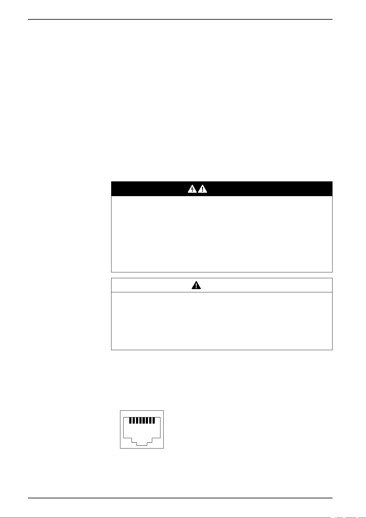
Serial Interface
1 8
Specifications
Division 2 hazardous location regulations require that all cable connections be
provided with adequate strain relief and positive interlock. As this product does not
provide adequate strain relief for the USB connection (USB micro-B interface) on
this product, use only non-incendive USB devices. Never connect or disconnect a
cable while power is applied at either end of the cable. All communication cables
should include a chassis ground shield. This shield should include both copper
braid and aluminum foil.
The outer diameter of the cable must be suited to the inner diameter of the cable
connector strain relief so that a reliable degree of strain relief is maintained.
The serial interface is not isolated. The SG (signal ground) and FG (frame ground)
terminals are connected inside this product.
You can switch the communication method between RS-232C and RS-485 via the
software.
NOTE: For information on how to connect controllers and other types of
equipment, refer to the corresponding device driver manual of your screen
editing software.
DANGER
ELECTRIC SHOCK AND FIRE
When using the SG terminal to connect an external device to this product:
• Verify that a ground loop is not created when you set up the system.
• Connect the SG terminal to remote equipment when the external device is
not isolated.
• Connect the SG terminal to a known reliable ground connection to reduce
the risk of damaging the circuit.
Failure to follow these instructions will result in death or serious injury.
CAUTION
LOSS OF COMMUNICATION
• Do not put excessive stress on the communication ports of all connections.
• Securely attach communication cables to the panel wall or cabinet.
• Use a RJ-45 connector that has a functional locking tab.
Failure to follow these instructions can result in injury or equipment
damage.
NOTE: Use within the rated current.
RS-232C/RS-485
RJ45 connector
NOTE: When setting up RS-485 communication, the cable diagram for some
28 EIO0000004129_00
equipment may require polarization on the terminal side. Change the setting
for polarization with your screen editing software.
Page 29

Specifications
Pin No. RS-232C/RS-485
Signal name Direction Description
1 RD (RXD) Input Receive Data (RS-232C)
2 SD (TXD) Output Send Data (RS-232C)
3 NC
4 D1 Input/Output Transfer Data (RS-485)
5 D0 Input/Output Transfer Data (RS-485)
6 RS (RTS) Output Request To Send
7
8 SG
Shell FG
NC
-
-
-
-
No connection
No connection
Signal Ground
Functional Ground
EIO0000004129_00 29
Page 30

Dimensions
140.4
5.53
29.85
1.18
13.9
0.55
101.1
3.98
(A)
(B)
(C)
mm
in
What’s in This Chapter
HMISTM6200 External Dimensions ................................................................ 30
HMISTM6400 External Dimensions ................................................................ 32
HMISTM6BOX External Dimensions ............................................................... 34
Rear Module Installation Adapter External Dimensions .................................... 35
Display Module/Rear Module Separation Cable Dimensions.............................36
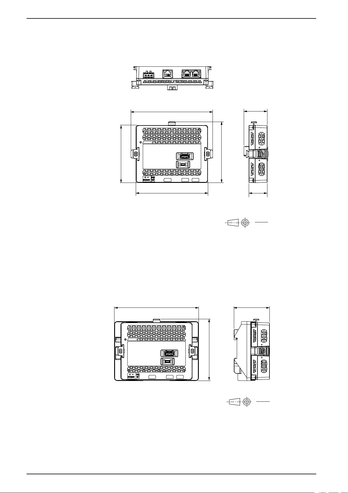
HMISTM6200 External Dimensions
Display Module Dimensions
Dimensions
A. Front
B. Left
C. Bottom
30 EIO0000004129_00
Page 31

Dimensions
145.6
5.73
53.95
2.12
108.23
4.26
(A) (B)
(C)
5.45
0.21
mm
in
Dimensions When Rear Module Attached to Display Module
A. Front
B. Left
C. Bottom
NOTE: See the following for dimensions of rear module only.
Rear Module Dimensions, page 34
EIO0000004129_00 31
Page 32

HMISTM6400 External Dimensions
201.2
7.92
33
1.3
17.1
0.67
137.2
5.4
(A) (B)
(C)
mm
in
Display Module Dimensions
Dimensions
A. Front
B. Left
C. Bottom
32 EIO0000004129_00
Page 33

Dimensions
201.2
7.92
57.7
2.27
137.2
5.4
(A) (B)
(C)
mm
in
Dimensions When Rear Module Attached to Display Module
A. Front
B. Left
C. Bottom
NOTE: See the following for dimensions of rear module only.
Rear Module Dimensions, page 34
EIO0000004129_00 33
Page 34
HMISTM6BOX External Dimensions
145.6
5.73
(A) (B)
(C)
41.4
1.63
108.23
4.26
102
4.06
128
5.04
32.5
1.28
mm
in
(A) (B)
150.49
5.92
109.97
4.33
63.3
2.49
mm
in
Rear Module Dimensions
Dimensions
A. Front
B. Right
C. Bottom
Dimensions When Installation Adapter Attached
A. Front
B. Right
NOTE: See the following for dimensions of Rear Module Installation Adapter
only.
Rear Module Installation Adapter External Dimensions, page 35
34 EIO0000004129_00
Page 35

Dimensions
(A) (B)
150.49
5.92
105.49
4.15
38.3
1.51
30
1.18
5
0.2
1.5
0.06
36.95
1.45
(D)
mm
in
mm
in
(C)
Rear Module Installation Adapter External Dimensions
Rear Module Installation Adapter Dimensions
A. Front
B. Right
C. Bottom
D. Rear
EIO0000004129_00 35
Page 36

Dimensions with Separation Cable Attached
8
0.31
25.2
0.99
(A) (B)
150.49
5.92
105.49
4.15
5
0.2
1.5
0.06
mm
in
38.3
1.51
30
1.18
(*1)
(A) (B)
46.57
1.83
80.34
3.16
75.15
2.96
31
1.22
39.9
1.57
8
0.31
mm
in
Dimensions
A. Front
B. Right
*1
To assemble this product, you need 20 mm (0.78 in) or more space to bend the
rubber portion at the end of the cable.
Display Module/Rear Module Separation Cable Dimensions
36 EIO0000004129_00
A. Front
B. Right
Page 37

Installing and Wiring
A B
Installing and Wiring
What’s in This Chapter
Installation .................................................................................................... 37
Separate Installation...................................................................................... 44
HMISTM6BOX Installation ............................................................................. 50
Wiring the Power Supply ................................................................................ 53
USB Cable Clamp ......................................................................................... 58
Installation
Precautions for Building into an End-use Product
The display module of this product is designed for use on flat surfaces of IP65F,
UL 50/50E, Type 1, Type 4X (indoor use only), Type 12 and Type 13 enclosures.
Be aware of the following when building this product into an end-use product:
• The rear module of this product is not approved as an enclosure. When
building this product into an end-use product, be sure to use an enclosure
that satisfies standards as the end-use product’s overall enclosure.
• This equipment is an open-type device and is meant to be installed in an
enclosure suitable for the environment. Install in an enclosure where the
equipment is inaccessible without the use of tools.
• Install this product in an enclosure with mechanical rigidity.
• This product is not designed for outdoor use. UL certification obtained is for
indoor use only.
• Install and operate the display module with its front panel facing outward.
NOTE: IP65F is not part of the UL certification.
Installation Requirements
• Check that the installation wall or cabinet surface is flat, in good condition and
has no jagged edges. Metal reinforcing strips may be attached to the inside of
the wall, near the panel-cut, to increase its rigidity.
• Decide on the thickness of the enclosure wall, based on the level of strength
required. Even if the installation wall thickness is within the recommended
range for the Panel Cut Dimensions, depending on wall’s material, size, and
installation location of this product and other devices, the installation wall
could warp. To prevent warping, the installation surface may need to be
strengthened.
• Check that the ambient air temperature and the ambient humidity are within
their specified ranges in Environmental Specifications, page 22. When
installing this product in a cabinet or enclosure, the ambient air temperature is
the cabinet’s or enclosure’s internal and external temperature.
A. Internal temperature
EIO0000004129_00 37
Page 38
Installing and Wiring
C
0...30°0...30°
mm
in
100
3.94
100
3.94
100
3.94
100
3.94
100
3.94
100
3.94
100
3.94
B. External temperature
• Be sure that heat from surrounding equipment does not cause this product to
exceed its standard operating temperature.
• When mounting this product in portrait orientation, ensure that the right side
of this product faces up. In other words, the DC power connector should be at
the top.
NOTE: For portrait orientation mounting, make sure your screen editing
software supports the function.
C. Power connector
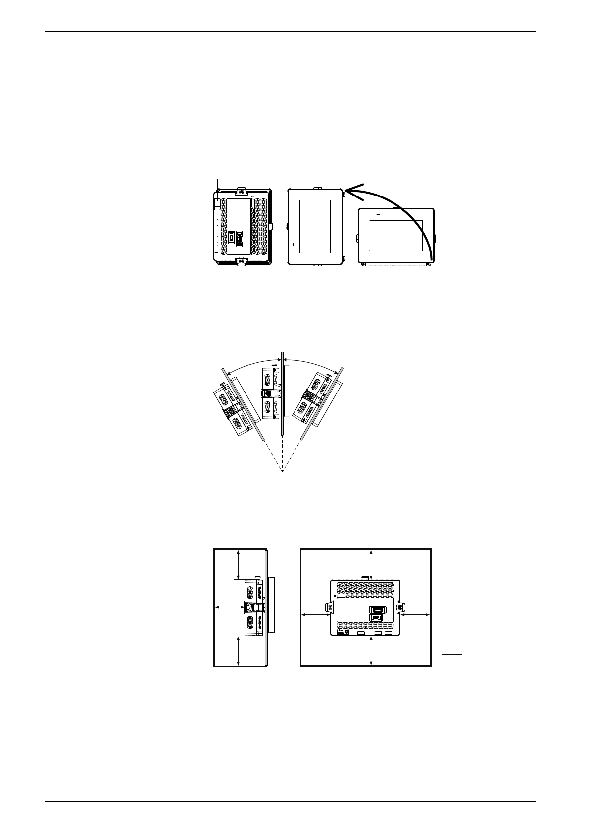
• When installing this product in a slanted position, the product face should not
incline more than 30°.
• For easier maintenance, operation and improved ventilation, install this
product at least 100 mm (3.94 in) away from adjacent structures and other
equipment as shown in the following illustration:
• The panel must be designed to avoid any induced vibration resonance on the
rear module exceeding an amplitude factor of 10 and to avoid any induced
permanent vibration resonance. To reduce the resonance use the spacer
(sold separately).
38 EIO0000004129_00
Page 39

Installing and Wiring
D
B
C
A
NOTICE
EQUIPMENT DAMAGE
When transporting a panel with the product installed, remove its rear module.
Failure to follow these instructions can result in equipment damage.
Pressure Differences
When applying and installing this product, it is important that steps are taken to
eliminate any pressure difference between the inside and the outside of the
enclosure in which this product is mounted. Higher pressure inside the enclosure
can cause delamination of the front membrane of the display. Even a small
pressure difference inside the enclosure will act on the large area of the
membrane and can result in sufficient force to delaminate the membrane and thus
cause failure of the touch capability. Pressure differences can often occur in
applications where there are multiple fans and ventilators moving air at different
rates in different rooms. Please follow these techniques to ensure that this
product's function is not impacted by this mis-application:
1. Seal all conduit connections inside of the enclosure, especially those that
lead to other rooms that may be at a different pressure.
2. Where applicable, install a small weep hole at the bottom of the enclosure to
allow equalization of the internal and external pressure.
Panel Cut Dimensions
Based on the panel cut dimensions, open a mount hole on the panel.
A B C
22.5 mm (+0/-0.3 mm)
(0.88 in [+0/-0.01 in])
4.0 mm (+0/-0.2 mm)
(0.15 in [+0/-0.007 in])
30.0 mm (+0/-0.2 mm)
(1.18 in [+0/-0.007 in])
Panel thickness recommended range:
Panel material Thickness range (D)
Steel 1.5... 6.0 mm (0.06... 0.23 in)
Glass fiber reinforced plastics (minimum GF30) 3.0... 6.0 mm (0.12... 0.23 in)
About Spacer
If the panel thickness does not meet the conditions for use with the product, you
can use an optional spacer.
EIO0000004129_00 39
Page 40
Installing and Wiring
A
D
B
C
E
Product number HMIZM6MP2 HMIZM6MP4
Spacer size (W x H x D)
Spacer material Stainless steel Stainless steel
145 x 105 x 2 mm
(5.71 x 4.13 x 0.08 in)
204 x 140 x 2 mm
(8.03 x 5.51 x 0.08 in)
The thickness and material of panels you can use the spacer are as follows.
Panel material HMISTM6200 HMISTM6400
Steel 1 ... 1.5 mm (0.04 ... 0.06 in) 1 ... 1.5 mm (0.04 ... 0.06 in)
Glass fiber reinforced plastics
(minimum GF30)
Other plastic 1 ... 3 mm (0.04 ... 0.12 in) not possible
1 ... 3 mm (0.04 ... 0.12 in) 2 ... 3 mm (0.08 ... 0.12 in)
A. Display module
B. Panel
C. Display module fixing nut
D. Anti-rotation tee
E. Spacer
Installation Procedure
This section describes how to install the rear module and display module to the
panel.
DANGER
HAZARD OF ELECTRIC SHOCK, EXPLOSION, OR ARC FLASH
• Remove all power from the device before removing any covers or elements
of the system, and prior to installing or removing any accessories, hardware,
40 EIO0000004129_00
or cables.
• Unplug the power cable from both this product and the power supply prior to
installing the product.
• Always use a properly rated voltage sensing device to confirm power is off
where and when indicated.
• Replace and secure all covers or elements of the system before applying
power to this product.
Failure to follow these instructions will result in death or serious injury.
Page 41
Installing and Wiring
A
D
B
C
E
NOTICE
EQUIPMENT DAMAGE
Always use the installation gasket.
Failure to follow these instructions can result in equipment damage.
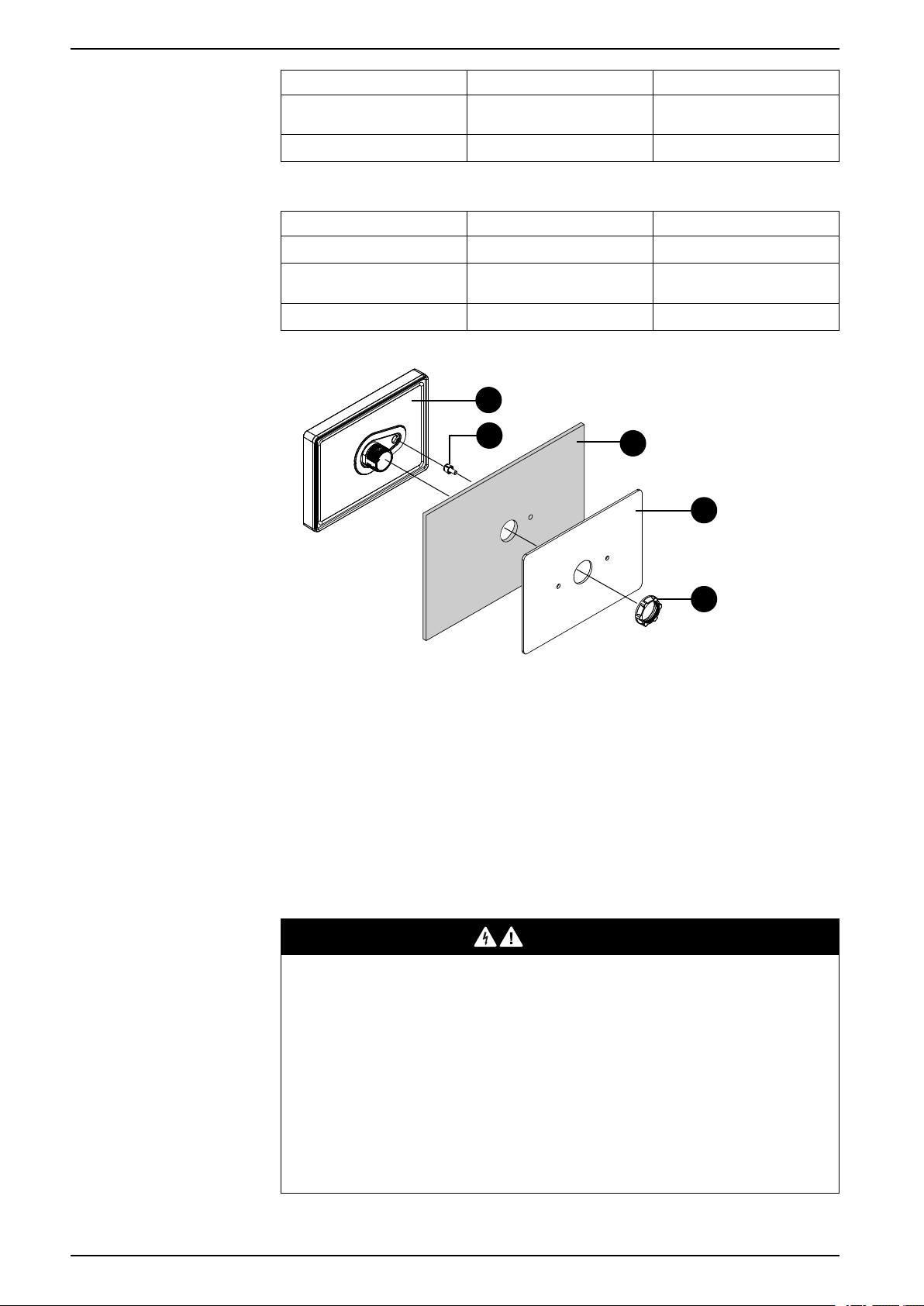
1. Place the display module on a clean and level surface with the screen facing
down.
2. Check that the gasket is seated securely into the bezel groove, which runs
around the perimeter of the display panel frame.
NOTE: Always use the installation gasket, since it absorbs vibration in
addition to repelling water. For the procedure on replacing the installation
gasket, refer to Replacing the Installation Gasket, page 63.
3. Based on this product's Panel Cut Dimensions, page 39, open a mount-hole
on the panel.
4. Insert the display module and the anti-rotation tee into the panel hole from the
front side. Use the socket wrench to tighten the nut. The necessary torque for
the nut is 1.2 to 2.0 N•m (10.62 to 17.70 lb-in).
NOTE:
• The anti-rotation tee is used to install the display module horizontally
on the panel. When you do not use an anti-rotation tee, applying
2.5 N•m (22.12 lb-in) or more force to the display module could cause
the product to rotate. By using an anti-rotation tee, 6 N•m
(53.10 lb-in) or more force could cause the product to rotate.
• If the panel thickness does not meet the specified conditions, use the
spacer (sold separately).
A. Display module
B. Panel
C. Display module fixing nut
D. Anti-rotation tee
E. Socket wrench
EIO0000004129_00 41
Page 42

Installing and Wiring
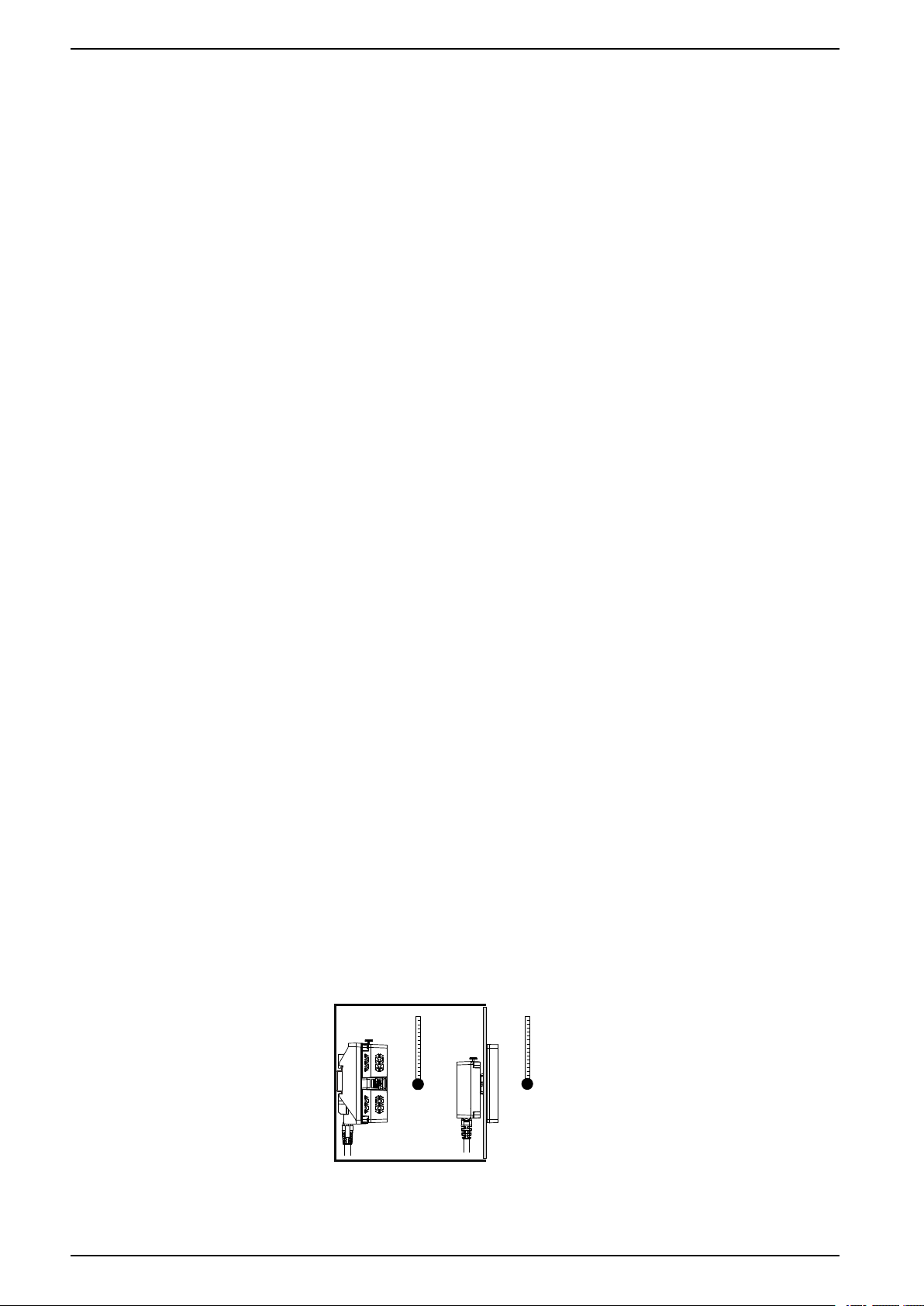
5. If the panel thickness is 3.8 mm (0.15 in) or less, push in the bumper on the
rear module until you hear a click. If the panel thickness is more than 3.8 mm
(0.15 in), do not change the bumper position.
NOTE: To return the bumper to its original position, use a screwdriver or
other tool as a lever to push the bumper up.
Removal Procedure
6. Insert and push the rear module straight in to the display module, until they
lock into place.
This section describes how to remove the rear module and display module from
the panel.
42 EIO0000004129_00
Page 43

Installing and Wiring
DANGER
HAZARD OF ELECTRIC SHOCK, EXPLOSION, OR ARC FLASH
• Remove all power from the device before removing any covers or elements
of the system, and prior to installing or removing any accessories, hardware,
or cables.
• Unplug the power cable from both this product and the power supply prior to
removing the product.
• Always use a properly rated voltage sensing device to confirm power is off
where and when indicated.
Failure to follow these instructions will result in death or serious injury.
NOTICE
EQUIPMENT DAMAGE
Be sure to remove the rear module from the display module without twisting.
Failure to follow these instructions can result in equipment damage.
1. Push and hold the button at the top of the rear module, and pull the rear
module straight out.
2. Remove the nut and the display module from the panel.
EIO0000004129_00 43
Page 44
Separate Installation
A B
Introduction
This section describes how to install the display module and rear module
separately.
Use the following optional products to mount the rear module on the DIN rail and
connect it to the display module mounted on the panel. For information about
optional products, refer to Accessories, page 17.
• Display Module/Rear Module Separation Cable
• Rear Module Installation Adapter
Precautions for Building into an End-use Product
The display module of this product is designed for use on flat surfaces of IP65F,
UL 50/50E, Type 1, Type 4X (indoor use only), Type 12 and Type 13 enclosures.
Be aware of the following when building this product into an end-use product:
• The rear module of this product is not approved as an enclosure. When
building this product into an end-use product, be sure to use an enclosure
that satisfies standards as the end-use product’s overall enclosure.
• This equipment is an open-type device and is meant to be installed in an
enclosure suitable for the environment. Install in an enclosure where the
equipment is inaccessible without the use of tools.
• Install this product in an enclosure with mechanical rigidity.
• This product is not designed for outdoor use. UL certification obtained is for
indoor use only.
• Install and operate the display module with its front panel facing outward.
NOTE: IP65F is not part of the UL certification.
Installing and Wiring
Installation Requirements for Separate Installation
• Check that the installation wall or cabinet surface is flat, in good condition and
has no jagged edges. Metal reinforcing strips may be attached to the inside of
the wall, near the panel-cut, to increase its rigidity.
• Decide on the thickness of the enclosure wall, based on the level of strength
required. Even if the installation wall thickness is within the recommended
range for the Panel Cut Dimensions, depending on wall’s material, size, and
installation location of this product and other devices, the installation wall
could warp. To prevent warping, the installation surface may need to be
strengthened.
• Check that the ambient air temperature and the ambient humidity are within
their specified ranges in Environmental Specifications, page 22. When
installing this product in a cabinet or enclosure, the ambient air temperature is
the cabinet’s or enclosure’s internal and external temperature.
A. Internal temperature
44 EIO0000004129_00
Page 45

Installing and Wiring
0...30°0...30°
mm
in
100
3.94
100
3.94
100
3.94
100
3.94
100
3.94
100
3.94
100
3.94
B. External temperature
• Be sure that heat from surrounding equipment does not cause this product to
exceed its standard operating temperature.
• When mounting the display module in portrait orientation, ensure that the
right side of this product faces up.
NOTE: For portrait orientation mounting, make sure your screen editing
software supports the function.
• When installing the display module in a slanted position, the product face
should not incline more than 30°.
• For easier maintenance, operation and improved ventilation, install this
product at least 100 mm (3.94 in) away from adjacent structures and other
equipment as shown in the following illustration:
• The panel must be designed to avoid any induced vibration resonance on the
rear module exceeding an amplitude factor of 10 and to avoid any induced
permanent vibration resonance. To reduce the resonance use the spacer
(sold separately).
NOTICE
EQUIPMENT DAMAGE
EIO0000004129_00 45
When transporting the cabinet or enclosure with the product installed, remove
its rear module.
Failure to follow these instructions can result in equipment damage.
Page 46

Pressure Differences
When applying and installing this product, it is important that steps are taken to
eliminate any pressure difference between the inside and the outside of the
enclosure in which this product is mounted. Higher pressure inside the enclosure
can cause delamination of the front membrane of the display. Even a small
pressure difference inside the enclosure will act on the large area of the
membrane and can result in sufficient force to delaminate the membrane and thus
cause failure of the touch capability. Pressure differences can often occur in
applications where there are multiple fans and ventilators moving air at different
rates in different rooms. Please follow these techniques to ensure that this
product's function is not impacted by this mis-application:
1. Seal all conduit connections inside of the enclosure, especially those that
lead to other rooms that may be at a different pressure.
2. Where applicable, install a small weep hole at the bottom of the enclosure to
allow equalization of the internal and external pressure.
Installation Procedure on DIN Rail and Panel
This section describes how to install the rear module on a DIN rail and the display
module to the panel.
Installing and Wiring
DANGER
HAZARD OF ELECTRIC SHOCK, EXPLOSION, OR ARC FLASH
• Remove all power from the device before removing any covers or elements
of the system, and prior to installing or removing any accessories, hardware,
or cables.
• Unplug the power cable from both this product and the power supply prior to
installing the product.
• Always use a properly rated voltage sensing device to confirm power is off
where and when indicated.
• Replace and secure all covers or elements of the system before applying
power to this product.
Failure to follow these instructions will result in death or serious injury.
NOTICE
EQUIPMENT DAMAGE
Always use the installation gasket.
Failure to follow these instructions can result in equipment damage.
1. Connect the separation cable to the rear module installation adapter. Affix the
screws on both sides of the cable connector to secure the cable to the
adapter.
46 EIO0000004129_00
Page 47

Installing and Wiring
2
1
2. Position the top groove of the rear module installation adapter on the top
edge of the DIN rail.
NOTE: Install the adapter on a DIN rail compatible with IEC 60715
TH35-7.5.
3. Push down on the adapter until the bottom groove of the installation adapter
fits under the DIN rail.
4. Insert and push the rear module straight in to the adapter, until they lock into
place.
5. Place the display module on a clean and level surface with the screen facing
down.
6. Check that the gasket is seated securely into the bezel groove, which runs
around the perimeter of the display panel frame.
NOTE: Always use the installation gasket, since it absorbs vibration in
addition to repelling water. For the procedure on replacing the installation
gasket, refer to Replacing the Installation Gasket, page 63.
7. Based on this product's Panel Cut Dimensions, page 39, open a mount-hole
on the panel.
EIO0000004129_00 47
Page 48
Installing and Wiring
A
D
B
C
E
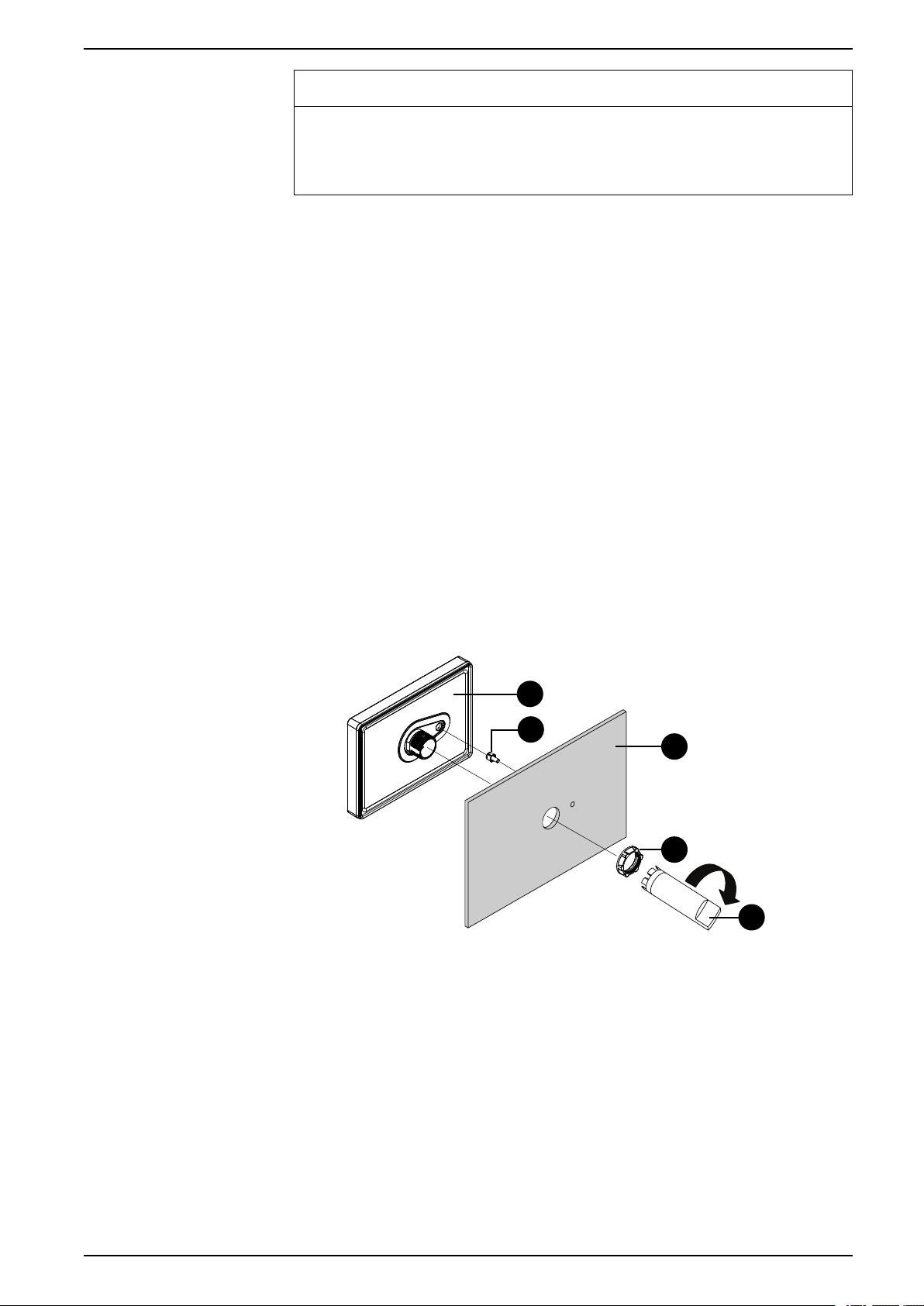
8. Insert the display module and the anti-rotation tee into the panel hole from the
front side. Use the socket wrench to tighten the nut. The necessary torque for
the nut is 1.2 to 2.0 N•m (10.62 to 17.70 lb-in).
NOTE:
• The anti-rotation tee is used to install the display module horizontally
on the panel. When you do not use an anti-rotation tee, applying
2.5 N•m (22.12 lb-in) or more force to the display module could cause
the product to rotate. By using an anti-rotation tee, 6 N•m
(53.10 lb-in) or more force could cause the product to rotate.
• If the panel thickness does not meet the specified conditions, use the
spacer (sold separately).
A. Display module
B. Panel
C. Display module fixing nut
D. Anti-rotation tee
E. Socket wrench
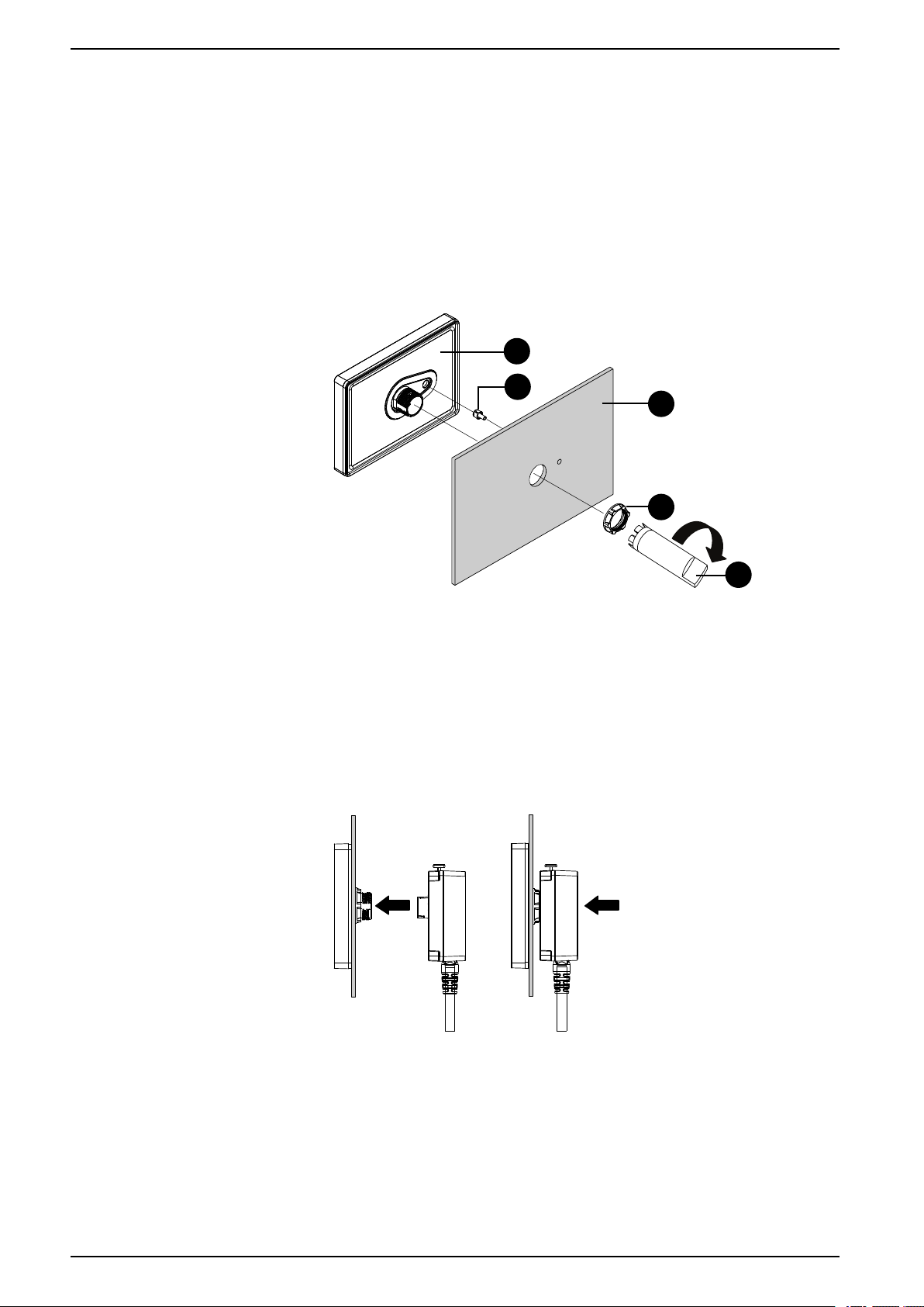
9. Insert and push the separation cable straight in to the display module, until
they lock into place.
Removal Procedure from DIN Rail and Panel
This section describes how to remove the rear module from a DIN rail and the
display module from the panel.
48 EIO0000004129_00
Page 49

Installing and Wiring
1
2
DANGER
HAZARD OF ELECTRIC SHOCK, EXPLOSION, OR ARC FLASH
• Remove all power from the device before removing any covers or elements
of the system, and prior to installing or removing any accessories, hardware,
or cables.
• Unplug the power cable from both this product and the power supply prior to
removing the product.
• Always use a properly rated voltage sensing device to confirm power is off
where and when indicated.
Failure to follow these instructions will result in death or serious injury.
NOTICE
EQUIPMENT DAMAGE
Be sure to remove the separation cable from the display module without
twisting.
Failure to follow these instructions can result in equipment damage.
1. Push and hold the button at the top of the rear module, and pull the rear
module straight out.
2. Push down on the rear module installation adapter and unhook the bottom
part of the adapter from the DIN rail.
EIO0000004129_00 49
Page 50

Installing and Wiring
3. Push and hold the button at the top of the separation cable, and pull the
separation cable straight out.
4. Remove the nut and the display module from the panel.
HMISTM6BOX Installation
Precautions for Installing to an End-use Product
Be aware of the following when installing this product to an end-use product:
• This equipment is an open-type device and is meant to be installed in an
enclosure suitable for the environment. Install in an enclosure where the
equipment is inaccessible without the use of tools.
• Install this product in an enclosure with mechanical rigidity.
Installation Requirements for HMISTM6BOX
• Check that the installation wall or cabinet surface is flat, in good condition and
has no jagged edges. Metal reinforcing strips may be attached to the inside of
the wall, near the installation location, to increase its rigidity.
• Depending on wall’s material, size, and installation location of this product
and other devices, the installation wall could warp. To prevent warping, the
installation surface may need to be strengthened.
• Check that the ambient air temperature and the ambient humidity are within
their specified ranges in Environmental Specifications, page 22. When
installing this product in a cabinet or enclosure, the ambient air temperature is
the cabinet’s or enclosure’s internal and external temperature.
50 EIO0000004129_00
Page 51

Installing and Wiring
A B
mm
in
100
3.94
100
3.94
100
3.94
100
3.94
100
3.94
100
3.94
100
3.94
A. Internal temperature
B. External temperature
• Be sure that heat from surrounding equipment does not cause this product to
exceed its standard operating temperature.
• For easier maintenance, operation and improved ventilation, install this
product at least 100 mm (3.94 in) away from adjacent structures and other
equipment as shown in the following illustration:
• The panel must be designed to avoid any induced vibration resonance on the
rear module exceeding an amplitude factor of 10 and to avoid any induced
permanent vibration resonance. To reduce the resonance use the spacer
(sold separately).
EQUIPMENT DAMAGE
When transporting a panel with the product installed, remove its rear module.
Failure to follow these instructions can result in equipment damage.
Installation Procedure on DIN Rail
HAZARD OF ELECTRIC SHOCK, EXPLOSION, OR ARC FLASH
• Remove all power from the device before removing any covers or elements
of the system, and prior to installing or removing any accessories, hardware,
or cables.
• Unplug the power cable from both this product and the power supply prior to
installing or removing the product.
• Always use a properly rated voltage sensing device to confirm power is off
where and when indicated.
• Replace and secure all covers or elements of the system before applying
power to this product.
Failure to follow these instructions will result in death or serious injury.
NOTICE
DANGER
EIO0000004129_00 51
Page 52

Installing and Wiring
2
1
1. Position the top groove of the rear module installation adapter on the top
edge of the DIN rail.
NOTE: Install the adapter on a DIN rail compatible with IEC 60715
TH35-7.5.
2. Push down on the adapter until the bottom groove of the installation adapter
fits under the DIN rail.
3. Insert and push the rear module straight in to the adapter, until they lock into
place.
52 EIO0000004129_00
Page 53

Installing and Wiring
1
2
Removal Procedure from DIN Rail
HAZARD OF ELECTRIC SHOCK, EXPLOSION, OR ARC FLASH
• Remove all power from the device before removing any covers or elements
of the system, and prior to installing or removing any accessories, hardware,
or cables.
• Unplug the power cable from both this product and the power supply prior to
installing or removing the product.
• Always use a properly rated voltage sensing device to confirm power is off
where and when indicated.
• Replace and secure all covers or elements of the system before applying
power to this product.
Failure to follow these instructions will result in death or serious injury.
1. Push and hold the button at the top of the rear module, and pull the rear
module straight out.
DANGER
2. Push down on the rear module installation adapter and unhook the bottom
part of the adapter from the DIN rail.
Wiring the Power Supply
DC Power Cord Preparation
• Make sure the ground wire is either the same or heavier gauge than the
power wires.
• Do not use aluminum wires in the power supply's power cord.
• If the ends of the individual wires are not twisted correctly, the wires may
create a short circuit.
• The conductor type is solid or stranded wire.
EIO0000004129_00 53
Page 54

Installing and Wiring
mm
in
7
0.28
FG
+
-
• Use copper wire rated for 75 °C (167 °F) or higher.
• Use UL Listed power source with LPS (Limited Power Source) or Class 2
output.
NOTE: UL listed cables have been investigated for wiring use inside of the
installation panel or service access area only.
Power cord diameter 0.75...2.5 mm
Conductor type Solid or stranded wire
Conductor length
Recommended driver Flat-head screwdriver (size 0.6 x 3.5)
*1
For UL compatibility, use AWG 14 or AWG 13.
How to Connect the DC Power Cord
HAZARD OF ELECTRIC SHOCK, EXPLOSION, OR ARC FLASH
• Remove all power from the device before removing any covers or elements
of the system, and prior to installing or removing any accessories, hardware,
or cables.
• Remove power before wiring this product’s power terminals.
• Always use a properly rated voltage sensing device to confirm power is off.
• Replace and secure all covers or elements of the system before applying
power to this product.
• Use only the specified voltage when operating this product. This product is
designed to use 24 Vdc. Always check whether your device is DC powered
before applying power.
• Since this product is not equipped with a power switch, be sure to connect a
power switch to the power supply.
• Be sure to ground this product’s FG terminal.
Failure to follow these instructions will result in death or serious injury.
DANGER
2
(18...13 AWG)
*1
NOTE:
• The SG (signal ground) and FG (frame ground) terminals are connected
inside this product.
• When the FG terminal is connected, be sure the wire is grounded. Not
grounding this product can result in excessive electromagentic
interference (EMI).
DC Power Connector
54 EIO0000004129_00
Page 55
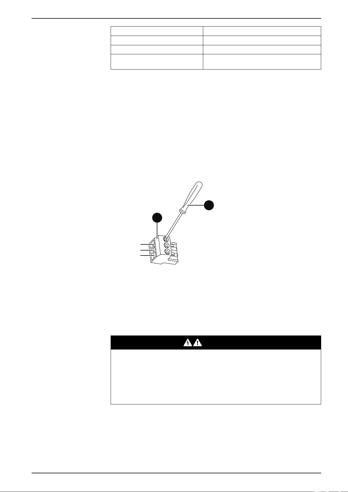
Installing and Wiring
FG
+
-
B
A
Connection Wire
+
-
FG Grounded terminal. Connect the FG terminal properly
NOTE: Part number XBTZGPWS1
Connection Procedure
1. Confirm the power cord is not connected to the power supply.
2. Check the rated voltage.
3. Strip the membrane of the power cord, and twist the wire ends.
4. Insert each power cord wire into its corresponding hole. Fasten the screws of
the DC power connector to clamp the wire in place.
NOTE:
• The necessary torque is 0.56 N•m (5 lb-in).
• Do not solder the stranded wires.
24 Vdc
0 Vdc
to ground.
5. After inserting all three power cord wires, insert the DC power connector into
Power Supply Precautions
SHORT CIRCUIT, FIRE, OR UNINTENDED EQUIPMENT OPERATION
• Install and fasten this product in an installation panel or cabinet prior to
• Securely attach power cables to an installation panel or cabinet.
• Avoid excessive force on the power cable.
Failure to follow these instructions will result in death or serious injury.
Improving Noise/Surge Resistance
• This product’s power cord should not be bundled with or kept close to main
A. DC power connector
B. Flat-blade screwdriver (size 0.6 x 3.5)
the power connector on this product.
DANGER
connecting power supply and communication lines.
circuit lines (high voltage, high current), power lines, or input/output lines, and
their various systems should be kept separate. When power lines cannot be
wired via a separate system, use shielded cables for input/output lines.
EIO0000004129_00 55
Page 56

Installing and Wiring
(B)
(A)
(C)
(A)
(B)
(C)
FG
(D)
(E)
(F)
• Make the power cord as short as possible, and be sure to twist the ends of the
wires together (i.e. twisted pair cabling) from close to the power supply unit.
• If there is an excess amount of noise on the power supply line, connect a
noise reducing transformer, noise filter, or other before turning on the power.
• Connect a surge protection device to handle power surges.
• To increase noise resistance, attach a ferrite core to the power cable.
Power Supply Connections
• When supplying power to this product, connect the power as shown below.
A. Main power
B. This product
C. Other unit
• Use UL Listed power source with LPS (Limited Power Source) or Class 2
output.
• The following shows a surge protection device connection:
A. Lightning
B. Lightning rod
C. Ground
D. This product
E. Provide adequate distance
F. Surge protection device
• Attach a surge protection device to prevent damage to this product as a result
of a lightning-induced power surge from a large electromagnetic field
generated from a direct lightning strike. We also strongly recommend to
connect the crossover grounding wire of this product to a position close to the
ground terminal of the surge protection device.
It is expected that there will be an effect on this product due to fluctuations in
grounding potential when there is a large surge flow of electrical energy to the
lightning rod ground at the time of a lightning strike. Provide adequate
distance between the lightning rod grounding point and the surge protection
device grounding point.
56 EIO0000004129_00
Page 57

Installing and Wiring
FG
(B)
(A) (C)
(B)(A)
Grounding
• If the voltage variation is outside the prescribed range, connect a regulated
power supply.
A. Regulated power supply
B. Twisted-pair cord
C. This product
Independent Grounding
Always ground the FG (functional ground) terminal. Be sure to separate this
product from the FG of other devices as shown below.
A. This product
B. Other equipment
Precautions
• Check that the grounding resistance is 100 Ω or less.
• The FG wire should have a cross sectional area 2 mm2(AWG14) or greater*1.
Create the connection point as close as possible to this product, and make
the wire as short as possible. When using a long grounding wire, replace the
thin wire with a thicker wire, and place it in a duct.
• The SG (signal ground) and FG (frame ground) terminals are connected
internally in this product. When connecting the SG line to another device, be
sure that no ground loop is formed.
*1
Observe local codes and standards.
*1
Common Grounding
Electromagnetic Interference (EMI) can be created if devices are improperly
grounded. EMI can cause loss of communication. If exclusive grounding is not
possible, use a common grounding point as shown in the configuration below. Do
not use any other configuration for common grounding.
EIO0000004129_00 57
Page 58

Correct grounding
(B)(A)
(B)(A)
A. This product
B. Other equipment
Incorrect grounding
Installing and Wiring
A. This product
B. Other equipment
USB Cable Clamp
Attaching USB Clamp Type A
When using a USB device, attach a USB cable clamp to the USB interface to
prevent the USB cable from being disconnected.
58 EIO0000004129_00
Page 59

Installing and Wiring
27...43.5 mm
(1.06...1.71 in)
A
WARNING
EXPLOSION HAZARD
• Verify the power, input, and output (I/O) wiring are in accordance with
Class I, Division 2 wiring methods.
• Substitution of any components may impair suitability for Class I, Division 2.
• Do not disconnect equipment while the circuit is live or unless the area is
known to be free of ignitable concentrations.
• Remove power before attaching or detaching any connectors to or from this
product.
• Ensure that power, communication, and accessory connections do not place
excessive stress on the ports. Consider the vibration in the environment
when making this determination.
• Securely attach power, communication, and external accessory cables to the
panel or cabinet.
• Use only commercially available USB cables.
• Use only non-incendive USB configurations.
• Suitable for use in Class I, Division 2, Groups A, B, C, D Hazardous
Locations.
• Confirm that the USB cable has been attached with the USB cable clamp
before using the USB interface.
Failure to follow these instructions can result in death, serious injury, or
equipment damage.
NOTE: Watch your fingers. The edge of the clip is sharp.
1. Mount the clip to the USB mark
The clip matches the 27 to 43.5 mm (1.06 to 1.71 in) length of the USB
connector.
2. Align the clip and the USB cable connector shell. Adjust the position of the
holes where the clip is attached. To ensure stability, select the clip-hole
position that is closest to the base of the connector shell.
connector shell so that it overlaps.
A. Hole for tie to pass through
EIO0000004129_00 59
Page 60

Installing and Wiring
1
2
3
4
B
3. As shown, pass the tie through the clip hole. Next, turn the tie and pass it
through the head so that the USB cable can pass through the center of the tie
loop. The clip is now attached to the USB cable.
NOTE:
• Check the direction of the head beforehand. Make sure the USB
cable is through the center of the tie loop and that the tie can pass
through the head.
• You can substitute the tie provided with HMIZGCLP1, or other
commercially available ties with a width of 4.8 mm (0.19 in) and
thickness of 1.3 mm (0.05 in).
4. While pressing the grip on the clip, insert the cable from step 3 all the way into
the USB host interface. Make sure that the clip tab is secured to the USB
cable attached to this product.
B. USB Type A interface
Removing USB Clamp Type A
Remove the USB cable while pushing the grip section of the clip.
Attaching USB Clamp mini-B
When using the USB micro-B cable (option), you can use the USB mini-B clamp
included in the Accessory kit (sold separately) to prevent the cable from being
disconnected.
60 EIO0000004129_00
Page 61
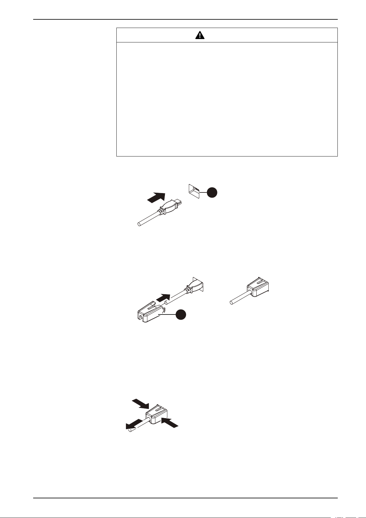
Installing and Wiring
A
B
1
1
2
WARNING
EXPLOSION HAZARD
• Verify the power, input, and output (I/O) wiring are in accordance with
Class I, Division 2 wiring methods.
• Substitution of any components may impair suitability for Class I, Division 2.
• Confirm that the USB cable has been fixed with the USB clamp before using
the USB interface.
• Remove power before attaching or detaching any connectors to or from this
product.
• Use the USB (micro-B) interface for temporary connection only during
maintenance and setup of the device.
• Do not use the USB (micro-B) interface in hazardous locations.
Failure to follow these instructions can result in death, serious injury, or
equipment damage.
1. Insert the USB cable into the USB (micro-B) interface.
2. Attach the USB clamp to fix the USB cable in place. Insert the USB holder
into the USB (micro-B) interface.
B. USB clamp
Removing USB Clamp mini-B
Remove the USB clamp by pressing the tabs from the sides.
A. USB interface
EIO0000004129_00 61
Page 62

Maintenance
Regular Cleaning
Cleaning the Product
Maintenance
What’s in This Chapter
Regular Cleaning .......................................................................................... 62
Periodic Check Points.................................................................................... 62
Replacing the Installation Gasket.................................................................... 63
Replacing the Battery ....................................................................................63
Replacing the Backlight .................................................................................63
NOTICE
EQUIPMENT DAMAGE
• Power off this product before cleaning it.
• Do not use hard or pointed objects to operate the touch panel.
• Do not use paint thinner, organic solvents, or a strong acid compound to
clean the unit.
Failure to follow these instructions can result in equipment damage.
When this product gets dirty, wipe this product except for the display face with a
soft, dry cloth or a soft cloth soaked in only water and wrung tightly. Wipe the
display face with a soft cloth soaked in water with a neutral detergent and wrung
tightly.
Periodic Check Points
Operation Environment
• Is the ambient air temperature within the allowable range? Refer to
Environmental Specifications, page 22.
• Is the ambient air humidity within the specified range? Refer to Environmental
Specifications, page 22.
When this product is inside a panel, the ambient environment refers to the interior
of the panel.
Electrical Specifications
• Is the input voltage appropriate? Refer to Electrical Specifications, page 22.
• Are all power cords and cables connected properly? Are there any loose
cables?
• Are all mounting brackets holding the unit securely?
• Are there scratches or traces of dirt on the installation gasket?
Unit Disposal
When disposing this product, dispose it in a manner appropriate to, and in
accordance with, your country's industrial machinery disposal/recycling standards.
62 EIO0000004129_00
Page 63

Maintenance
A
Replacing the Installation Gasket
The installation gasket provides protection against dust and moisture.
The gasket must be inserted correctly into the groove for moisture resistance for
the display module.
GASKET AGING
• Inspect the gasket periodically as required by your operating environment.
• Change the gasket at least once a year, or as soon as scratches or dirt
become visible.
Failure to follow these instructions can result in equipment damage.
EQUIPMENT DAMAGE
Be careful not to stretch the gasket unnecessarily.
Failure to follow these instructions can result in equipment damage.
NOTICE
NOTICE
1. Place the display module on a flat, level surface, with the display face pointing
2. Remove the gasket from the display module.
3. Attach the new gasket to the display module.
Replacing the Battery
Not replaceable. Please contact your local distributor.
down.
A. Installation gasket
Replacing the Backlight
Not replaceable. Please contact your local distributor.
EIO0000004129_00 63
Page 64

Schneider Electric
35 rue Joseph Monier
92500 Rueil Malmaison
France
+ 33 (0) 1 41 29 70 00
www.se.com
As standards, specifications, and design change from time to time,
please ask for confirmation of the information given in this publication.
© 2020 – Schneider Electric. All rights reserved.
EIO0000004129_00
 Loading...