

Smart-UPS™On-Line Isolation and Step-Down Transformer SRT5KTF
Safety Messages
Read the instructions carefully to become familiar with the equipment before attempting to install, op e rate, service or
maintain the transformer. The following special messages may appear throughout this manual or on the equipment to
warn of potential hazards or to call attention to information that clarifies or simplifies a procedure.
The addition of this symbol to a Danger or Warning product safety label indicates that an electrical hazard
exists that will result in personal injury if the instructions are not followed.
This is the safety alert symbol. It is used to alert you to potential personal injury hazards. Obey all safety
messages that follow this sy mb ol to avoid possible injury or death.
CAUTION
CAUTION indicates a hazardous situation which, if not avoided, could result in minor or moderate injury.
NOTICE
NOTICE is used to address practices not related to physical injury.
Safety Information
• Adhere to all national and local electrical codes.
• All wiring must be performed by a qualified electrician.
•Changes and modifications to this unit not expressly approved by APC coul d void the warranty.
• This transformer is intended for indoor use only.
• Do not operate this transformer in direct sunlight, in contact with fluids, or where there is excessive dust
hu
midity.
• Be sure the air vents on the transform e r are not blocked. Allow adequate space for proper ventilation .
• For a transformer with a factory installed power cord, connect the transformer power cable directly to an ou
eceptacle of the UPS. Do not use surge protectors or extension cords.
r
• The equipment is heavy. Always practice safe lifting techniques adequate for the weight of the equipment.
•For rack mount transformers, always install the transformer directly above the UPS in rack-m ount conf iguratio ns
Th
e UPS must be installed below the transformer.
• Always install peripheral equipment above the UPS in rack-mount configurations.
• Additional safety information can be found in the Safety Guide supplied with this unit .
or
tput
.

Electrical safety
• For models with a hardwired input, the connection to the branch circuit (mains) must be performed by a
q
ualified electrician.
•230 V models only: In order to maintain compliance with the EMC directive for products sold in Europe, output
cords attached to the transformer must not exceed 10 meters in length.
• The protective earth conductor for the transformer carries the leakage current from the load devices (compu
uipment). An insulated ground conductor is to be installed as part of the branch circuit that supplies
eq
ransformer. The conductor must have the same size and insulation material as the grounded and unground
t
b
ranch circuit supply conductors. The conductor will typically be green and with or without a yellow stripe.
• The UPS input ground conductor must be properly bonded to protective earth at the service panel.
• If the UPS input power is supplied by a separately derived system, the ground conductor must be properly
bonded at the supply transformer or motor generator set.
Hardwire safety
• Verify that all branch circuit (mains) and low voltage (control) circuits are deenergized, and locked out before
i
nstalling cables or making connections, whether in the junction box or to the transformer.
• Wiring by a qualified electrician is required.
• Check national and local codes before wiring.
•
openings that allow access to transformer hardwire terminals must be covered. Failure to do so may result in
All
personal injury or equipment damage.
• Select wire size and connectors according to national and local codes.
ter
the
ed
General information
• The model and serial numbers are located on a small, rear panel label.
Recycle the package materials or save them for reuse.
•
FCC Class A radio frequency warning
This equipment has been tested and found to comply with the limits for a Class A digital device, pursuant to part 15 of
the FCC Rules. These limits are intended to provide reasonable protection against harmful interfe rence wh en the
equipment is operated in a commercial environment. This equipment generates, uses, and can radiate radio frequency
energy and, if not installed and used in accordan ce with the instruction manual, m ay cause harm ful interference to radio
communications. Operation of this equipment in a residential area is likely to cause harmful interference in which case
the user will be required to correct the interference at his own expense.
Product Information
The Smart-UPS™ SRT transformer is intended for use as a st ep-down transformer. This transformer can also function as
an isolation transform e r.
The transformer can be installed in a standard 19-inch rack.
The transformer can be installed as a tower or in a rack. For rack-mount configuration use only the APC by Schneider
Electric rack model SRTRK2.
Isolation and Step-Down Transformer SRT5KTF2
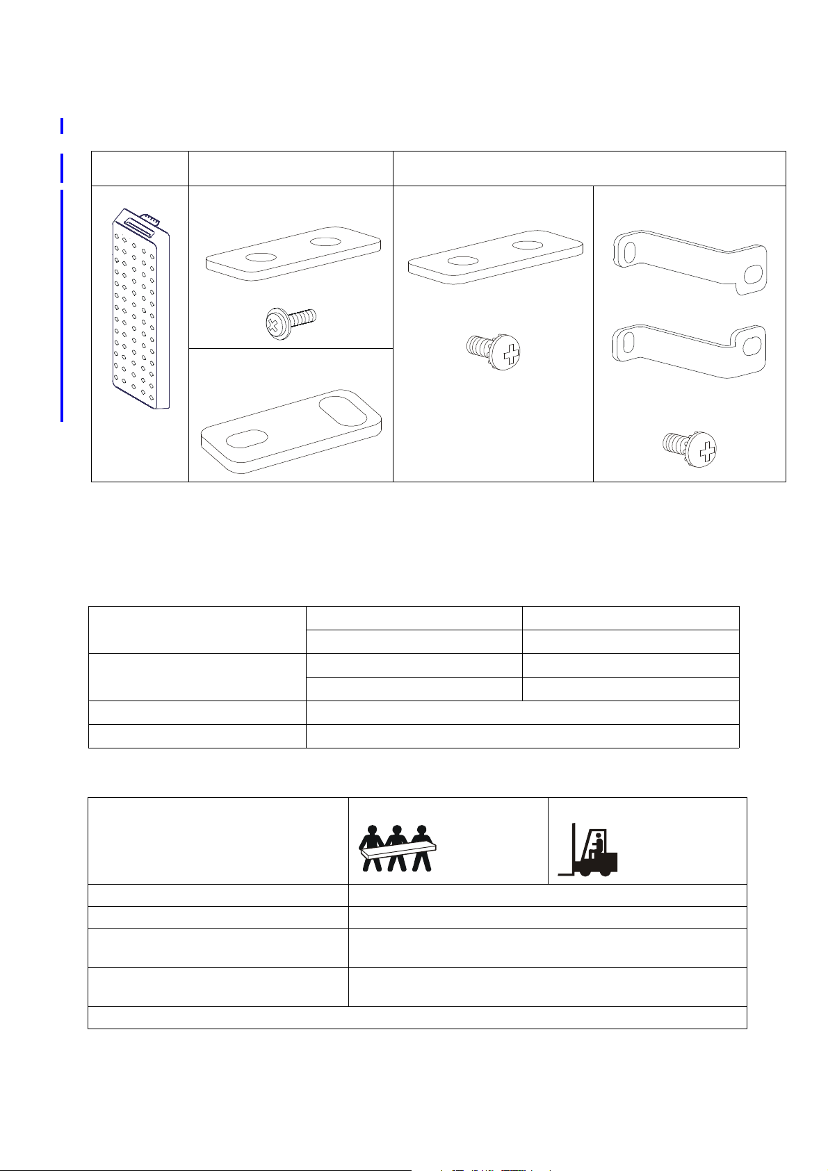
Package Contents
Inspect the contents upon receipt. Notify the carrier and dealer if the unit is damaged.
Use with all
models
Front bezel 1 tie bracket to secure the UPS to
SRT5K/6K/8K/10K UPS Use with SRT3000XLT UPS
the transformer
2 screws to secure tie bracket
2 tie brackets to secure the UPS to
the transformer
Use with
1 tie bracket to secure the UPS to
the transformer
1 pan head screw to secure tie
bracket
Specifications
For additional specifications refer to the APC by Schneid er Electric web site, www.apc.com.
Top and bottom tie brackets to
secure the UPS with transformer
2 pan head screws to secure tie
brackets
Environmental
Operating
Temperature
Storage
Operating
Maximum Elevation
Storage
Humidity
Protection Class
0% to 95% relative humidity, non condensing
IP 20 rating
Physical
Lifting guidelines 32 - 55 kg (70 - 120lb)
Unit weight, without packaging 56.82 kg (125 lb)
Unit weight, with packaging 63.64 kg (140 lb)
Unit dimensions without packaging
Height x Width x Depth
Unit dimensions with packaging
Height x Width x Depth
The model and serial numbers are on a small label located on the rear panel.
432 mm x 130 mm x 660 mm
17 in x 5 in x 26 in
347 mm x 603 mm x 980 mm
13.68 in x 23.74 in x 38.6 in
0º to 40º C (32º to 104º F)
-15º to 45º C (5º to 113º F)
0 - 3,000 m (0 - 10,000 ft)
0 - 15,000 m (50,000 ft)
kg (> 120lb)
> 55
Isolation and Step-Down Transformer SRT5KTF 3
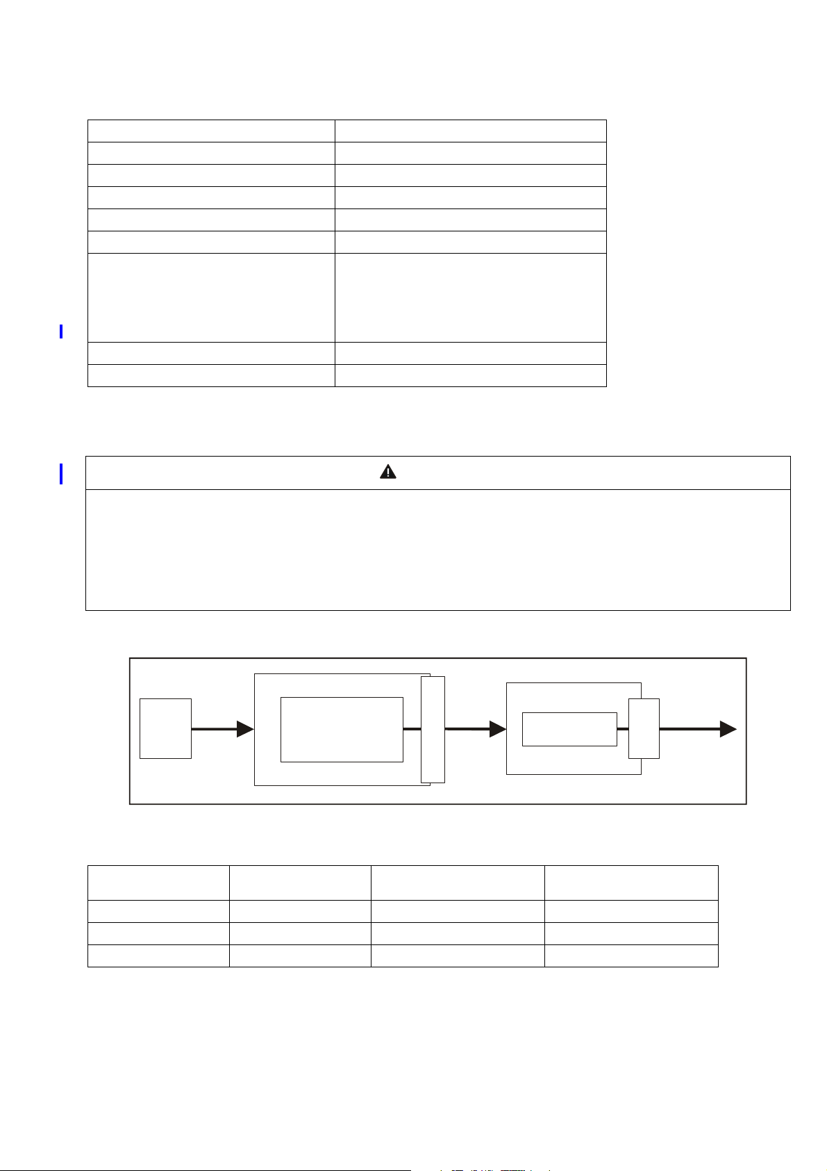
Electrical
suo1007a
Utility
Power
3 ft cable
L6-30 plug
Power
to Load
Equipment
Transformer
UPS
P
D
U
P
D
U
Nominal Input Voltage (Vac) 208 V, 220 V, 240 V
Input Voltage Range (Vac) 170 V - 280 V
Input Service Maximum Current (Amps) 30 A
Input Connection 3 ft cord with L6-30P
Line Frequency (Hz) 50/60 Hz
Nominal Output Voltage (Vac) 220 V / 240 V / 208 V / 110 V / 120 V
Output Receptacles
L6-20R
(2)
(1) L6-3
(1) L14(8)
0R
30R
5-20R (accepts both 5-20P and 5-15P)
Maximum Output Power (VA) 4800 VA
Maximum Output Power (Watt) 4800 W
Wiring Diagram
CAUTION
DAMAGE TO EQUIPMENT OR PERSONNEL
•Adhere to all national and local electrical codes.
•Wiring should be performed by a qualified electrician.
Failure to follow these instructions can result in equipment damage and minor or moderate injury
Typical system configuration
Utility voltage UPS output Input voltage selection
switch position
208 V 208 V 208 V 240 V / 208 V / 120 V
240 V 240 V 240 V 240 V / 208 V / 120 V
220 V 220 V 240 V 220 V / 110 V
Transformer output voltage
Isolation and Step-Down Transformer SRT5KTF4

Tower Installation
CAUTION
DAMAGE TO EQUIPMENT OR PERSONNEL
•The equipment is heavy. Always practice safe lifting techniques adequate for the weight of the equipment.
•Always use the recommended number of screws to secure brackets to the UPS and transformer.
•Always install the transformer to the left of the UPS when facing the front of the units.
•Always install the optional bypass panel to the left of the transformer when facing the front of the units.
Failure to follow these instructions can result in equipment damage and minor or moderate injury
Note: The transformer must be installed to the left of the UPS when facing the front of the units. If the configuration
includes the optional bypass panel, ensure that the bypass panel is installed to the left of the transformer when facing
the front of the units. Refer to the bypass panel manu al for installation instructions.
Tower t ransf ormer
Your UPS model may differ in appearance from those depicted in these graphics. The installation process is identical
for the following models:
•SRT5KXLT
•
SR
T6KXLT
•SRT8KXLT
•SRT10KXLT
Place the transformer to the left side of the UPS at the installation location.
suo1001a
suo1000a
Isolation and Step-Down Transformer SRT5KTF 5

Remove two screws at the top and bottom of the UPS.
suo1006c
Remove two screws at the top and bottom of the
transformer.
suo1002b
Reuse the screws removed in and to secure tie
brackets at the top and bottom of the transformer and
UPS.
su0051b
Install the tie brackets to the transformer and UPS.
suo100 3a
Isolation and Step-Down Transformer SRT5KTF6

Install the front bezel on the transformer.
suo1004a
Tower transformer SRT3000XLT model
Place the transformer to the left side of the UPS at the installation location.
suo1001a
suo1000a
Isolation and Step-Down Transformer SRT5KTF 7

Remove two screws at the top and bottom of the UPS.
suo1105a
s
u
o
1
1
0
1
b
suo10
04b
Remove two screws at the top and bottom of the
transformer.
su0051b
Reuse one screw removed in and one new pan head screw to secure the tie brackets at the top and bottom of the
transformer and UPS. Note: Mount the pan head screws to the UPS.
Install the tie brackets to the transformer and UPS.
suo1003c
Install the front bezel on the transformer.
Isolation and Step-Down Transformer SRT5KTF8

Connection and Startup Instructions
suo1005a
CAUTION
DAMAGE TO EQUIPMENT OR PERSONNEL
• Disconnect the mains input circuit breaker before installing or servicing the UPS or transformer or connected
equipment.
• Disconnect internal and external batteries before installing or servicing the UPS or connected equipment.
• The UPS contains internal and external batteries that may present a shock hazard even when disconnected
from the mains.
• UPS AC hardwired and pluggable outlets may be energized by remote or automatic control at any time.
• Disconnect equipment from the UPS before servicing any equipment.
• Do not use the UPS as a safety disconnect.
Failure to follow these instructions can result in equipment damage and minor or moderate injury
1. Ensure that the
transformer input cor d
is unplugged.
2. Remove the voltage
selection switch cover
.
3. Set the input voltage
selection switch to
match the utility voltage
of 208 or 240 VAC.
“Typical system
configuration” on
page 4.
4. If 240 V utility is used,
program the UPS output for 240 V. See the UPS user manual.
5. Install the voltage selection switch cover .
6. Plug applicable load equipment into the PDU receptacles on the transformer.
7. Plug the transformer input cord 1 into the appropriate PDU receptacle on the rear of the UPS.
8. Ensure that the output circuit breakers are ON.
9. Ensure that the input circuit breaker is ON.
Isolation and Step-Down Transformer SRT5KTF 9

Tower to Rack-Mount Conversion
CAUTION
DAMAGE TO EQUIPMENT OR PERSONNEL
• The equipment is heavy. Always practice safe lifting techniques adequate for the weight of the equipment.
• Always use the recommended number of screws to secure brackets to the UPS and transformer.
• Always install the transformer above the UPS in the rack.
• Always install the optional bypass panel above the transformer in the rack.
Failure to follow these instructions can result in equipment damage and minor or moderate injury
Note: The transformer must be installed directly above the UPS in the rack. If the configuration includes the optional
bypass panel, ensure that the bypass panel is installed above the transformer in the rack. Refer to the bypass panel
manual for installation instructions.
1. Install the transformer directly above the UPS in the rack. Refer to the Smart-UPS RT Tower to
Rack-mount Conversion Guide and the optional rail kit.
2. See the “Connection and Startup Instructions” on page 9 to complete the installation.
Service
If the transformer requires service do n ot re turn it to the dealer. Instead, follow these steps:
1. Contact APC by Schneider Electric Customer Service through the APC by Schneider Electric web site,
www.apc.com/support.
a. Note the model number of the transformer, the serial number, and the date purchased. If you call APC by
Schneider Electric Customer Service, a technician will ask you to describe the problem and try to solve it
over the phone, if possible. If this is not possible, the technician will issue a Retur n ed Material
Authorization Number (RMA#).
b. If the transformer is under warranty, repairs are free. If not, there is a repair charge.
2. Pack the transformer in its original packaging. If the original packing is no t available, refer to the APC by
Schneider Electric web site, www.apc.com/support, for information about obtaining a new set.
a. Pack the transformer properly to avoid damage in transit. Never use Styrofoam beads for packaging.
Damage sustained in transit is not covered under warranty.
3. Mark the RMA# on the outside of the package.
4. R eturn the transformer by insured, prepaid carrier to the address given to you by Customer Service.
Isolation and Step-Down Transformer SRT5KTF10

Limited Warranty
Schneider Electric IT Corporation (SEIT), warrants its products to be free from defects in materials and workmanship
for a period of two (2) years from the date of purchase. The SEIT obligation under this warranty is limited to repairing
or replacing, at its own sole option, any such defective products. Repair or replacement of a defective product or parts
thereof does not extend the original warranty period.
This warranty applies only to the original purchaser who must have properly registered the product within 10 days of
purchase. Products may be registered online at warranty.apc.com.
SEIT shall not be liable under the warranty if its testing and examination disclose that the alleged defect in the product
does not exist or was caused by end user or any third person misuse, negligence, improper installation, testing,
operation or use of the product contrary to SEIT recommendations or specifications. Further, SEIT shall not be liable
for defects resulting from: 1) unau thorized attem pts to repair or mod ify the product, 2) incorrect or inadequate electrical
voltage or connection, 3) inappropriate on site operation conditions, 4) Acts of God, 5) exposure to the elements, or 6)
theft. In no event shall SEIT have any liability under this warranty for any product where the serial number has been
altered, defaced, or removed.
EXCEPT AS SET FORTH ABOVE, THERE ARE NO WARRANTIES, EXPRESS OR IMPLIED, BY
OPERATION OF LAW OR OTHERWISE, APPLICABLE TO PRODUCTS SOLD, SERVICED OR
FURNISHED UNDER THIS AGREEMENT OR IN CONNECTION HEREWITH.
SEIT DISCLAIMS ALL IMPLIED WARRANTIES OF MERCHANTABILITY, SATISFACTION AND
FITNESS FOR A PARTICULAR PURPOSE.
SEIT EXPRESS WARRANTIES WILL NOT BE ENLARGED, DIMINISHED, OR AFFECTED BY AND NO
OBLIGATION OR LIABILITY WILL ARISE OUT OF, SEIT RENDERING OF TECHNICAL OR OTHER
ADVICE OR SERVICE IN CONNECTION WITH THE PRODUCTS.
THE FOREGOING WARRANTIES AND REMEDIES ARE EXCLUSIVE AND IN LIEU OF ALL OTHER
WARRANTIES AND REMEDIES. THE WARRANTIES SET FORTH ABOVE CONSTITUTE SEIT SOLE
LIABILITY AND PURCHASER EXCLUSIVE REMEDY FOR ANY BREACH OF SUCH WARRANTIES.
SEIT WARRANTIES EXTEND ONLY TO ORIGINAL PURCHASER AND ARE NOT EXTENDED TO ANY
THIRD PARTIES.
IN NO EVENT SHALL SEIT, ITS OFFICERS, DIRECTORS, AFFILIATES OR EMPLOYEES BE LIABLE
FOR ANY FORM OF INDIRECT, SPECIAL, CONSEQUENTIAL OR PUNITIVE DAMAGES, ARISING
OUT OF THE USE, SERVICE OR INSTALLATION OF THE PRODUCTS, WHETHER SUCH DAMAGES
ARISE IN CONTRACT OR TORT, IRRESPECTIVE OF FAULT, NEGLIGENCE OR STRICT LIABILITY
OR WHETHER SEIT HAS BEEN ADVISED IN ADVANCE OF THE POSSIBILITY OF SUCH DAMAGES.
SPECIFICALLY, SEIT IS NOT LIABLE FOR ANY COSTS, SUCH AS LOST PROFITS OR REVENUE,
WHETHER DIRECT OR INDIRECT, LOSS OF EQUIPMENT, LOSS OF USE OF EQUIPMENT, LOSS OF
SOFTWARE, LOSS OF DATA, COSTS OF SUBSTITUANTS, CLAIMS BY THIRD PARTIES, OR
OTHERWISE.
NOTHING IN THIS LIMITED WARRANTY SHALL SEEK TO EXCLUDE OR LIMIT SEIT LIABILITY
FOR DEATH OR PERSONAL INJURY RESULTING FROM ITS NE GLIGE NCE OR ITS FRAUDULENT
MISREPRESENTATION OF TO THE EXTENT THAT IT CANNOT BE EXCLUDED OR LIMITED BY
APPLICABLE LAW.
To obtain service under warranty you must obtain a Returned Material Authorization (RMA) number from customer
support. Customers with warranty claims issues may access the SEIT worldwide customer supp ort network thro ugh the
APC W eb site: www.apc.com
the top of the web page to obtain information for customer support in your region. Products must be returned with
transportation charges prepaid and must be accompanied by a brief des cription o f the problem encountered and proof of
date and place of purchase.
. Select your co untry f rom the cou ntry select ion drop down m enu. Open th e Sup port ta b at
Isolation and Step-Down Transformer SRT5KTF 11

© 2016 APC by Schneider Electric. APC, the APC logo , Smart - UPS and PowerChute are owned by
Schneider Electric Industries S.A.S. or their affiliated companies. All other trademarks are property of
their respective owners.
EN 990-5431C
5/2016
 Loading...