

Page 1
Quick Guide 10.2015 QG EVE0105 B-(en)
SRD991 Intelligent Positioner
These instructions are to be used as a guide for quick start-up. For more detailed information, please refer
to the standard documents “Master Instructions” and “Product Specification Sheet”. These can be found
on our Website.
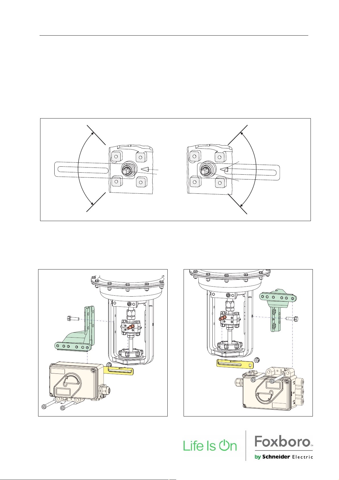
1. MOUNTING TO ACTUATORS
During operation, the flat side of the spindle 9 on the back of the positioner must always point towards
the arrow 26. The working angle around this position is ±45º.
2 6
2 6
9
9
Any mechanical backlash may be source of poor control, oscillation and hunting as well as long duration of
Autostart. Please use only original mounting parts and ensure that they are correctly mounted and tighten.
By not using the original feedback lever or by using them in an inappropriate way, the performance of the
positioner may be compromised.
MOUNTING TO LINEAR ACTUATORS
NAMUR Mounting - left hand -
NAMUR Mounting - right hand -
Page 2
2 SRD991 QG EVE0105 B-(en)
MOUNTING TO LINEAR ACTUATORS (cont’d)
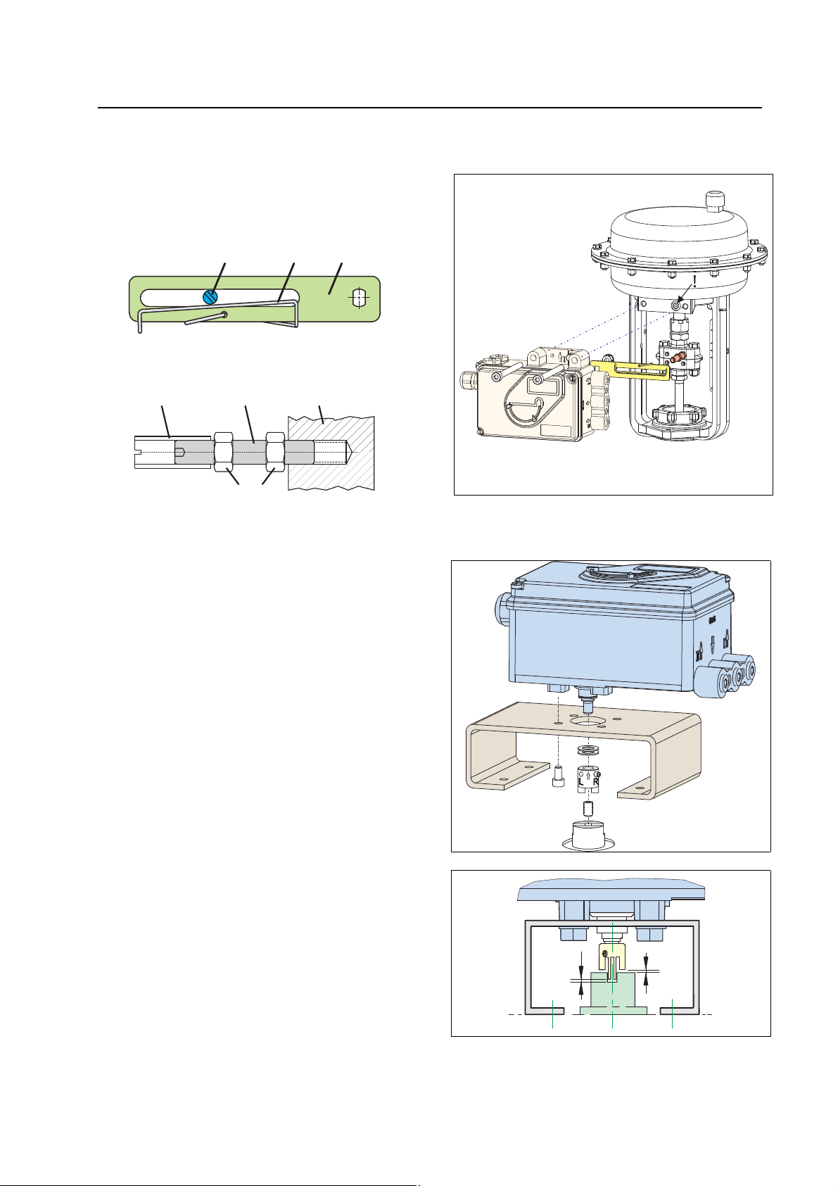
Feedback lever for linear actuators :
The carrier bolt B is in the slot of the feedback
lever A and the compensating spring F touches
the carrier bolt.
AB F
Carrier bolt B:
1 threaded sleeve 2 Stud 3 coupling piece
1 2 3
M 6
MOUNTING TO ROTARY ACTUATORS
• Do not tighten grub screw 4 against the thread
of spindle 9 ! (see next page).
• When in use the flat side of the spindle 9 must
move ( 0 ↔ 100%) in front of the arrow 26.
Direct Mounting
• When the product temperature rises, the drive
shaft 1 increases in length. Therefore, the rotary
adapter 3 must be mounted so that approx. 1
mm (0.04 in.) of clearance results between the
drive shaft 1 and the rotary adapter 3. This is
achieved by placing an appropriate number of
washers 5 on the feedback spindle 9 before
attaching the rotary adapter. Two washers
should result in a clearance of 1 mm.
> 1
> 1
Page 3
QG EVE0105 B-(en) SRD991 3
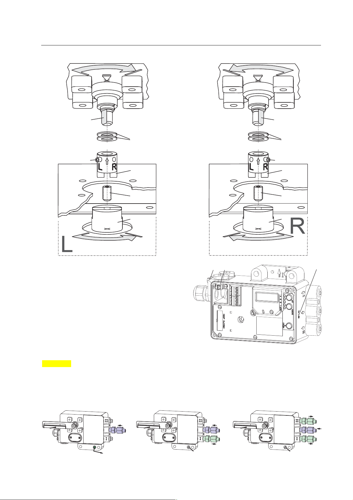
Actuator, left turning Actuator, right turning
9
5
4
3
2
1
2. CONNECTIONS
Check before mounting fittings and cable glands
that the threads are matching; otherwise the
housing can be damaged. The letter “G” on the
housing marks where the pneumatic connections
are in G 1/4 (otherwise NPT).
Ground
Connect earth cable to screw #1 (or screw #2 in
the electrical connection compartment).
9
5
4
3
2
1
# 1 # 2
" G "
PNEUMATIC CONNECTIONS
WARNING
To avoid any personal injury resulting from bursting of parts, do not exceed maximum supply pressure of
positioner and actuator. To avoid any personal injury or property damage from sudden or fast movement,
during air connection: Do not put your finger or other part at any time inside the valve or in any
moving part of the actuator or in the feedback lever mechanism. Do not touch the rear part of the
positioner at any time. Connect air supply only after connections y1 (and y2 for double acting) are done.
Air supply (s): 1.4 to 6 bar (but not more than the max. pressure of actuator), free of oil, dust and water
( - - )
s
( - - )
y 1
( - - )
( - - )
s
y 1
( - - )
!
Single acting, Direct mounting Single acting Double acting
s supply y1, y2 pneumatic outputs (--) closed
y 2
s
y 1
Page 4

4 SRD991 QG EVE0105 B-(en)
A
3. ELECTRICAL CONNECTIONS
The safety requirements of document EX EVE0001 as well as the requirements of PSS EVE0105 and
MI EVE0105 for SRD991 must be observed!
3.1 Setpoint Electric Terminal A
3.1.1 SRD991-xD (w/o communication)
SRD991-xH (HART)
1 1 + 1 2
3.1.3 SRD991-xP (PROFIBUS PA)
SRD991-xQ (FIELDBUS FF)
1 1 1 2
3.2 Inductive Limit Switch Electric Terminal C
3.2.1 SRD991-xxxT or U
3.2.3 SRD991-xxxV
Warning: For connection of micro switches please refer to MI (Master Instruction) and obey the
safety requirements described in document EX EVE0001.
3.3 Option Board Electric Terminal B
3.3.1 Two binary outputs (SRD991-xxP)
3.3.2 Two binary inputs (SRD991-xxB)
3.3.3 Position feedback 4 to 20 mA and 1 Alarm
3.3.4 Two binary in-/outputs (SRD991-xxE)
*
For intrinsically safe circuits please refer to certificate / data label for
max. operating voltages etc.
Input 4 to 20 mA
Bus connection acc. to IEC 1158-2
Supply voltage 9 to 32 V DC *
Two-wire proximity sensors, 3.2.2 SRD991-xxxR
acc. to DIN 19234 or NAMUR
5 1 + 5 2 4 1 + 4 2
Switching amplifier with
intrinsically safe control circuit
Switching amplifier with
intrinsically safe control circuit
4 2 5 24 1 + 4 3
Contact 2
Contact 1
Supply voltage 10 to 30 V DC
8 3 + 8 4 8 1 + 8 2
Two-wire system, acc. to DIN 19234
or switched output.
External power supply (e.g.
intrinsically safe control circuit
External power supply (e.g.
intrinsically safe control circuit
Binary inputs with internal supply for connection
1 5 + 1 6 1 3 + 1 4
of sensors or switches (switch closed for a
normal operation!)
3 1 + 3 2 8 1 + 8 2
(SRD991-xxQ ou SRD991-xxF)
Analog output 4-20 mA and Binary output Twowire system acc. to DIN 19234 or switched.
Two-wire system, supplied with
external power supply
External power supply (e.g.
intrinsically safe control circuit
8 1 + 8 2 8 3 + 8 4
Two-wire system acc. to DIN 19234 or
switched in-/output.
Binary in-/ output 4 to 20 mA,
Two-wire system, supplied with
external power supply
Binary in-/ output 4 to 20 mA,
Two-wire system, supplied with
external power supply
nalog output 4 to 20 mA,
Page 5

QG EVE0105 B-(en) SRD991 5
4. START UP (Setting by means of local keys and LCD)
After mounting the positioner on the actuator, air
and electrical input connected, you can start-up
the SRD. The positioner can be adjusted by means
of a local key-pad and LCD.
WARNING
To avoid any personal injury or property damage
from sudden or fast movement, d uring conf iguratio n:
Do not put your finger or other part at any time
inside the valve or in any moving part of the
actuator or in the feedback lever mechanism.
Do not touch the rear part of the positioner at
any time.
IN OPERATION:
An already configurated device may show the
following display:
87.5 %
Valve position
For configuration press (M) and Main menu
appears.
CONFIGURATION with push buttons and LCD:
If the SRD wasn’t configurated yet, the Main
menu*) appears automatically after power-up:
SRD Main Menu
1 Mounting
2 Autostart
3 Valve Action
(The selected item is displayed with dark background.)
In menu 1 you select the type of mounting: Press
keys (UP)+(DOWN) simultaneously to enter this
menu.
*) On delivery the menu language in the display is English.
The menu language can be changed over to another stored
language. For this select 9.8.2 [German] or 9.8.3 [as ordered]
and confirm with keys (UP)+(DOWN) (simultaneously).
Leave menu by repeated pressing of (M) key.
Process variable
Push buttons
(M)
Enter or
exit Main
menu
|-both simultaneously:-|
Enter / store
Select your ‘Type of mounting’ by pressing (UP) or
(DOWN).
1 Mounting
1.1 Lin left
1.2 Lin right
1.3 rot cclockw
Press keys (UP)+(DOWN) simultaneously to
confirm and save. The SRD moves back to Main
menu again.
SRD Main Menu
1 Mounting
2 Autostart
3 Valve Action
To enter next menu (= menu 2, Autostart) press
(UP) once:
SRD Main Menu
1 Mounting
2 Autostart
3 Valve Action
Now press keys (UP)+(DOWN) simultaneously to
enter menu ‘Autostart’.
(Continued on next page.)
(DOWN)
Previous
menu or
Parameter
(UP)
Next
menu or
Parameter
Page 6

6 SRD991 QG EVE0105 B-(en)
Several Autostart options are available . Select relevant Autostart by pressing (UP) or (DOWN):
2 Autostart
2.1 Endpoints
2.2 Standard
2.3 Enhanced
2.4 Smooth resp.
2.5 Fast resp.
Press keys (UP)+(DOWN) simultaneously to confirm and to launch Autostart. The automatic adaptation to
the actuator is composed of a sequence of steps indicated on the LCD.
With the last step the device is IN OPERATION:
87.5 %
Valve position
5 TROUBLE SHOOTING (For more details see MI EVE0105 E)
Autostart err 1
Description of message / LCD text Remedy
Air supply too low Check air supply
Feedback lever (linear actuator) or Coupling (rotary
actuator) incorrectly linked. Potentiometer moves
out of operating range of ± 47° of 0° position
Coupling (rotary actuator) incorrectly linked
(R and L interchanged)
Pneumatic output to actuator closed or untight.
When direct mounting onto FlowTop or FlowPak,
the screw plug y1-d is not removed
Mechanical stops not determinable Check spring movement of actuator /
When using a booster or spool valve, no control
parameters can be determined, since air capacity
is too high
Control parameter too high since air capacity is too
high (in general, oscillation in valve movement)
Possibly incomprehensible configuration data Reset configuration, see Menu 9.1
Optionboard err
Description of message / LCD text Remedy
Configured status of the SRD deviates from
existing version (e.g. Option board has been
inserted subsequently)
Bad contact Connections to terminals interchanged
Defective Exchange option board
Ctrl diff error
Description of message / LCD text Remedy
Actuator problems (high friction or blocked) Check actuator
Insufficient air supply Check air supply / air filter
Insufficient parametes for position controls,
for example, amplification too small
IP module or pneumatic amplifier defect Check with Menu 7; replace if necessary
Determines only the mechanical stops of actuator/ valve
Recommended for standard applications
Optimized control behaviour compared to Standard Autostart
Dampened control behaviour for e.g. smaller actuators
Undampened control behaviour for e.g. larger actuators
Process variable
87.5 %
Valve position
Ctrl diff error
Check mounting. Flat area points to arrow on
housing
Check mounting
Check pneumatic connections
check air supply / Check mounting
Device version is not suitable for this actuator;
select version with smaller air capacity or remove
booster
Use a booster or the version with spool valve.
Reduce control parameter prop.-gain (Menu 6.1
and 6.2) to Code 10 = value 26.6.
Check if correct option board has been connected
Confirm message by pressing keys (UP)+(DOWN)
simultaneously
Check connections
Tighten electronics
Check control paramter,
check pneumatic components
Diagnostic messages
see following table.
Page 7

QG EVE0105 B-(en) SRD991 7
y
6 MENU STRUCTURE FOR SRD991 / SRD960
SRD Main Menu
Menu Factory
configuration
1 Mounting
1.1 Lin left
1.2 Lin right
1.3 Rot cclockw
1.4 Rot clockw
1.5 Linear
2 Autostart
2.1 Endpoints
2.2 Standard
2.3 Enhanced
2.4 Smooth resp.
2.5 Fast resp.
3 Valve Action
3.1 SRD
3.1.1 Direct
3.1.2 Reverse
3.2 Feedback
3.2.1 Direct
3.2.2 Reverse
Description
Linear actuator, left-hand or direct mounting
Linear actuator, right-hand mounting
Rotary actuator, opening counter-clockwise
Rotary actuator, opening clockwise
For Top Mounting (only for SRD991)
Adaptation of the mechanical stops onl
Autostart recommended for standard application
Enh. Autostart. Optimized control behaviour compared to Standard Autostart
Enh. Autostart. Dampened control behaviour for e.g. smaller actuators
Enh. Autostart. Undampened control behaviour for e.g. larger actuators
Action of Positioner:
Valve opens with increasing setpoint value
Valve closes with increasing setpoint value
Action of Feedback Unit:
Increasing Current with increasing valve position
Decreasing Current with increasing valve position
4 Character
4.1 Linear
4.2 Eq Perc 1:50
4.3 Quick open
4.4 Customer
5 Limits/alarms
5.1 Lower limit 0 %
5.2 Cutoff low 1 %
5.3 Cutoff high 100 %
5.4 Upper limit 100 %
5.5 Splitr 0 % 4 mA
5.6 Splitr 100 % 20 mA
5.7 Lower Alarm -10 %
5.8 Upper Alarm 110 %
5.9 Valve 0% 4 mA
5.10 Valve 100% 20 mA
5.11 Stroke Range x° / 20 mm
5.12 Units SI
6 Parameters
6.1 Gain closing 15
6.2 Gain opening 2
6.3 Res time cl 7.5
6.4 Res time op 2.4
6.5 Rate lim cl 0.35
6.6 Rate lim op 0.35
6.7 Control gap 0.1
Linear characteristic
Equal percentage characteristic 1:50
Inverse equal percentage characteristic 1:50 (quick opening)
Custom characteristic (Configuration via DTM)
(Not locally available with LED versions of communication FF and Profibus)
Closing limit is set to input value
0%-tight sealing point is set to input value
100%-tight sealing point is set to input value
Opening limit is set to input value
Split range 0 %: input value corresponds to 0 %
Split range 100 %: input value corresponds to 100 %
Lower position alarm on output 1 is set to input value
Upper position alarm on output 2 is set to input value
Configuration of rated-stroke of 0% at 4 mA
Configuration of rated-stroke of 100% at 20 mA
Configuration of nominal travel
Configuration of temperature and pressure unit SI or Anglo US
P: Proportional gain for ‘close valve’
P: Proportional gain for ‘open valve’
I: Integration time for ‘close valve’
I: Integration time for ‘open valve’
T63: Setting time for ‘close valve’
T63: Setting time for ‘open valve’
Permitted dead band for control difference
7 Output
8 Setpoint
8.1 12.5% Steps Setpoint changes of 12.5% steps by using push buttons Up or Down
8.2 1% Steps Setpoint changes of 1% steps by using push buttons Up or Down
8.3 Do PST Start Partial Stroke Test
Continued on the next page
Manual setting of IP-Module for testing of pneumatic output
Manual setting of valve position
Page 8

8 SRD991 QG EVE0105 B-(en)
A
A
9 Workbench
9.1 Reset Config
9.2 Calib. 4 mA
9.3 Calib. 20 mA
9.4 Calib. -45°
9.5 Calib. +45°
9.6 Reset all 1 Resetting of configuration and Calibration (!) to “ex factory” setting for
9.7 Reset all 2 Resetting of configuration and Calibration (!) to “ex factory” setting for
9.8 Go Online
9.9 Menu Lang
9.9.1 English
9.9.2 Deutsch
9.9.3 Français
9.10 LCD orient
9.10.1 Normal
9.10.2 Flipped
9.11 Cal. Feedbk Calibration of output current of position transmitter
9.11.1 Cal. 4 mA Calibration of 0% at 4 mA
9.11.2 Cal 20mA Calibration of 100% at 20 mA
Resetting of configuration to setting “ex factory”
Calibrate input current to 4 m
Calibrate input current to 20 m
Calibrate position measuring value to –45°
Calibrate position measuring value to +45°
single-acting
double-acting
Setting position into mode Online (Service function only)
Language on LCD:
Standard English
Standard German
Preselected / freely definable
LCD Orientation:
Normal orientation of writing on LCD
Reverse orientation of writing on LCD
output
output
10 Profibus PA - Bus Address
10.1 Address LSB
10.2 Address MSB
10.3 Address 126
10 FOUNDATION Fieldbus H1
10.1 Simulate
Disabled
Enabled
10.2 Profile
Link Master
Basic Device
Profibus only.
Ratio from Dec. 0 / Hex 00 to Dec. 15 / Hex 0F
Ration from Dec. 0 / Hex 00 to Dec. 112 / Hex 70
Display of Bus Address from Dec. 1 to 127 (Hex 00 to 7F)
FF only.
Simulate disabled
Simulate enabled
Link Master active
Link Master de-activated
Invensys Systems, Inc.
38 Neponset Street
Foxboro, MA 02035
United States of America
Global Customer Support
Toll free: 1-866-746-6477
Global: 1-508-549-2424
Website:
http://support.ips.invensys.com
Copyright 2010-2016 Invensys Systems, Inc.
All rights reserved.
Invensys, Foxboro, and I/A Series are trademarks of Invensys Limited, its subsidiaries,
and affiliates. All other trademarks are the
property of their respective owners.
DOKT 534 022 302
FD-QG-PO-002-EN 0316
 Loading...