

Page 1
Installation Guide Smart-UPS
™
1200/1500 VA 100/120/230 Vac
Rack-Mount 1U
Important Safety Messages
Read the instructions carefully to beco me familiar with the equipment before trying to install, operate, se rvice or
maintain it. The following special mes sa ges may appear throughout this manual or on the equipment to warn of
poten t ia l ha zards or to c al l at te n ti o n to in f o r mation tha t cl ar i f ie s or sim p l ifies a proced u r e.
The addition of this symbol to a Caution product safet y label indicates that a haza rd exists that can res ult in
injury and product damage if the instructions are not followed.
The following safety messages may appear throughout this manual to warn of potential hazards.
CAUTION
CAUTION indicates a potentially haza rdous situation which, if not avoided, can result in equipment damage and minor or
modera te injury.
CAUTION
CAUTION indicates a potentially hazardous situation which, if not avoided, can result in equipment damage.
Safety and General Information
Inspect the package contents upon receipt. Notify the carrier and dealer if there is any
damage.
Read the Safety Guide supplied with this unit before installing the UPS.
• Adhere to all nation al and local electrical codes.
• This UPS is intended for indoor use only.
• Do not operate this UPS in direct sunlight, in contact with fluids, or where there is excessive dust or humidity.
•Be sure the air vents on the UPS are not block ed. Allow adequate space for prope r ventilation.
• The battery typically lasts for three to five years. Environmental factors impact battery life. Elevated ambien
mperatures, poo r quality utility power, and frequent short duration discharges will shorten battery life.
te
•
•
ct the UPS power cable directly to a wall outlet. Do not use surge protectors or extension cords.
Conne
T
he batteries are heavy. Remove the batteries prior to ins tallin g t he UPS in a rack.
t
Page 2
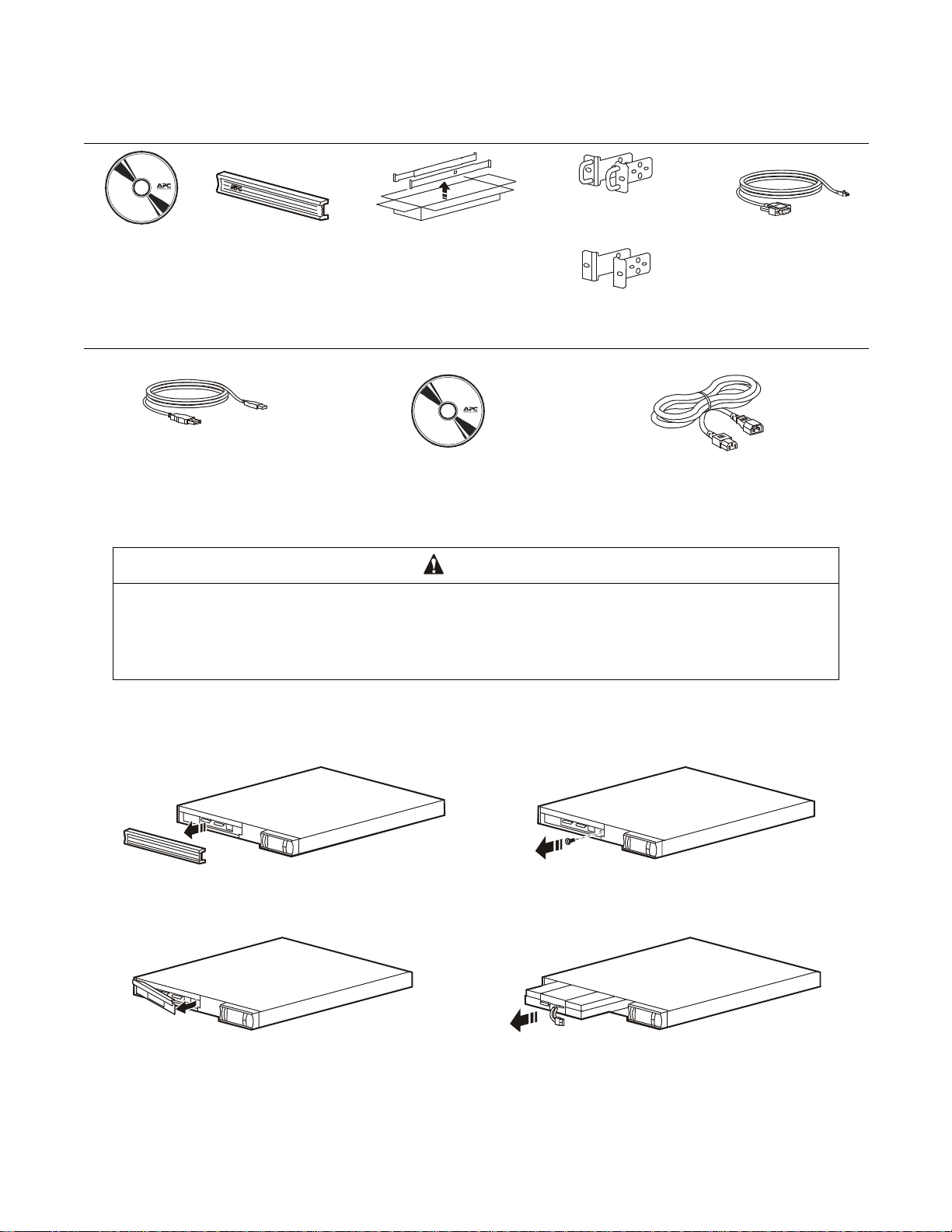
Inventory
su0704a
su0705a
All m o d els
Documentation
CD
Bezel
1U Rail Kit
with rails, cleats, screws
Rack-Mount brackets
100 Vac models
Rack-Mount brackets
120/230 Vac models
Serial cable
120 Vac/230 Vac models
USB cable
120 Vac/230 Vac models
Software CD
230 Vac models
2 Power cords
Installation
CAUTION
DAMAGE TO EQUIPMENT OR PERSONNEL
• The equipment is heavy. Always practice safe lifting techniques adequate for the weight of the equipment.
•The combined weight of the UPS and the battery pack is 24 kg (53 lb).
The battery pack weighs 10.5 kg (23 lb). Remove the battery pack before installing the UPS in a rack.
Failure to follow these instructions can result in equipment damage and minor or moderate injury
Remove the battery
Remove the bezel .
1
Remove the sc r ew that secur es the battery
2
compartment door.
Open the b attery comp a r tment door.
3
Smart-UPS 1200 VA 100 Vac Rack-Mount 1U / 1500 VA 120/230 Vac Rack-Mount 1U2
su0706a
Slide the batte ry o ut of the UPS. Do not pull on the
4
battery cable to remove the battery from the UPS.
su0707a
Page 3

Rack installation
CAUTION
DAMAGE TO EQUIPMENT OR PERSONNEL
• When installing equipment in a rack, always install load devices at the bottom of the rack.
• The UPS should always be installed above the peripheral devices in rack or stack configurations.
xxx
Failure to follow these instructions can result in equipment damage and minor or moderate injury
Note: The installation process is identical for both types of rack-mount brackets.
Secure the rail cleats and brackets to the UPS. Use two screws
1
for each rack-mount bracket and three screws for each rail cleat.
Install th e 1U Rail Kit included with the
2
UPS. Refer to the ins tallation instructio ns
provided with the rail kit.
Slide the UPS into the rack. Secure the brackets to
3
the rack u sing the s crews provided.
Install the battery compartment door.
5
su0708a
Slide the battery into the UPS.
4
su0710a
Secure the door with the screw previously removed.
6
su0709a
su0712a
su0713a
su0714a
Smart-UPS 1200 VA 100 Vac Rack-Mount 1U / 1500 VA 120/230 Vac Rack- M ount 1U 3
Page 4

Secure the two battery connectors as shown in the
7
diagram below.
Install the bezel on the front of the UPS.
8
Overview and Start Up
Front panel
Battery
1
Battery connector
2
Display interfac e
3
Bezel
4
Rear panels
1200/1500 VA 100/120 Vac
su0724a
su0715a
su0697a
1500 VA 230 Vac
su0699bsu0699c
1 Circuit breake r/Overload protec tion
2 UPS input
3 Controlled outlet group 1
4 Controlled outlet group 2
5 RJ45 connector - serial UPS monitoring port
6 USB port
7 SmartSlot for optional accessory ca rd
Smart-UPS 1200 VA 100 Vac Rack-Mount 1U / 1500 VA 120/230 Vac Rack-Mount 1U4
Page 5

Electrical connections
CAUTION
RISK OF EQUIPMENT DAMAGE
• Adhere to all local and national electrical codes.
•Wiring should be perf ormed by qualified electrician.
•
Failure to follow these instructions can result in equipment damage
ys connect the UPS to a grounded outlet.
Alwa
Outlet type and locat ion m ay vary.
su0628a
Display Interf ace
1 Online LED
2 On Battery LED
3 Fault LE D
4 Replace Battery LED
5
UP/DOWN arrow buttons
6 Display screen
7
ENTER button
8 UPS Output
9
ESCAPE button
ON/OFF button
su0701a
Smart-UPS 1200 VA 100 Vac Rack-Mount 1U / 1500 VA 120/230 Vac Rack- M ount 1U 5
Page 6

Select models are ENERGY STAR® qualified.
© 2013 APC by Schneider Electric. APC, the APC logo, and Smart-UPS ar e ow ned by Schneider
Electric Industries S.A.S., or their affiliated companies. Al l other trademarks are proper ty of thei r
respect ive owners .
EN 990-4326B-002
03/2013
 Loading...