

Page 1
Smart Sensor Series
SensorsField Devices
Installation Guide
1
Installation
Installation consists of mounting the module to the
wall then wiring power and data connections to a
controller.
The sensor can be mounted directly on drywall, or on
any electrical outlet box with no adapters required.
This sensor is for indoor use only and is not suitable
for use where condensation may occur.
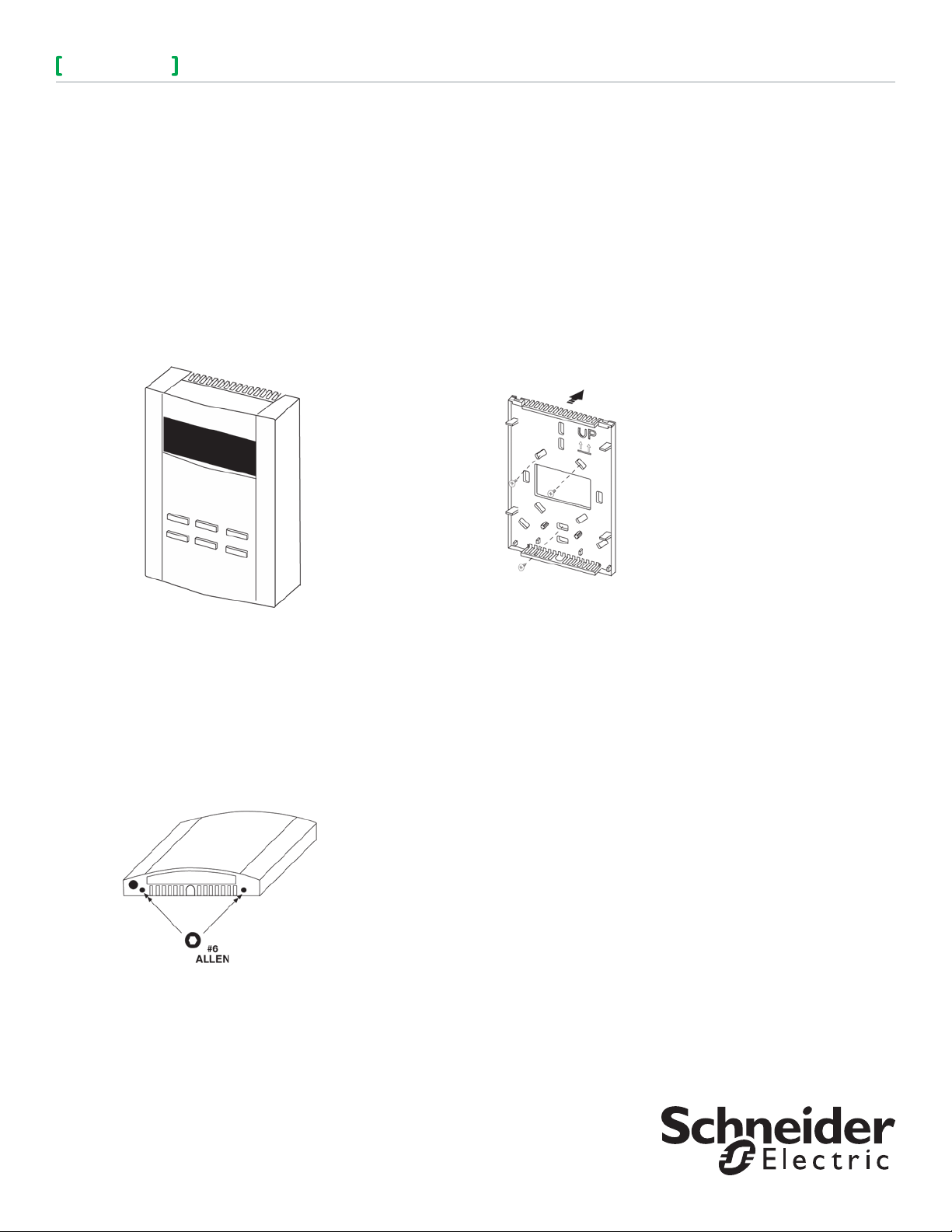
INSTALLING THE SENSOR AND BASE
To remove the sensor
The sensor is fastened to the base using Allen
screws.
1. Using a #6 Allen tool, turn the two Allen screws
located in the bottom of the sensor cover
clockwise (inward) until the sensor lifts off easily.
To install the base
Note: If you are mounting the sensor to an
existing electrical box, skip steps 1, 2 and
3. To prevent drafts from affecting the
Sensor reading, cover the openings in the
back of the base.
1. Place the base on the surface of the wall area
where the sensor is to be mounted and mark the
location of at least three mounting holes.
Figure 2. Placement of the base.
2. Drill the marked holes and insert wall anchors into
the surface.
3. Mount the base using at least three screws.
4. Guide your facility wiring into the large opening
of the base.
5. Connect your wires to the probe wires that are
part of the cover assembly using wire nuts.
6. Collect any slack wire, fold and tuck into the
base.
7. Place the cover on the mounted base.
8. Secure the cover by turning the Allen screws
counterclockwise (outward) until the cover is
locked in place. Refer to Figure 1.
Figure 1. Turn two Allen screws clockwise.
2. Remove the sensor by lifting the front bottom
outward.
Page 2
SensorsField Devices
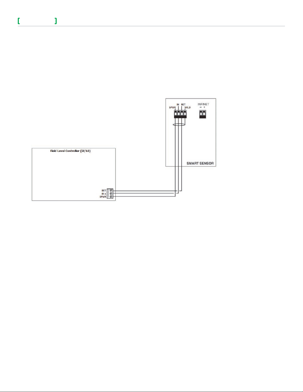
SMART SENSOR CONNECTION
The Smart Sensor bus consists of a three wire connection between the sensor and the controller, using the
dedicated three-terminal connector on the field level controller.
• RET
• IN x
• SPWR
The following illustrates the connection between the two units.
2
Figure 3. Smart Sensor wiring diagram.
TEMPERATURE INPUT TROUBLESHOOTING
1. Disconnect the wiring to the input and connect an ohm meter directly across the input wires at the
controller. Verify the measurement against the resistance to temperature chart found below.
2. Measure the resistance directly at the probe. If there is a significant difference between the resistance
measured at the probe and at the controller, then there is a resistance problem in the wiring, which will
affect the reading.
Note: When the controller no longer considers an input reading to be valid, it sets the ElecValue to
999.9. Each controller has two additional internal inputs. One is hard-wired to the reference
channel and the other is connected to ground. These two inputs are used for continuous software
calibration of the input circuit. If at any time either of these two inputs reads out of a predened
range, then the input routine will set the ElecValue of all inputs to 999.9.
chneider Electric | Buildings
S
F-27637-3
© 2014 Schneider Electric. All rights reserved.
May 2014 tl
Page 3

SensorsField Devices
Table-1. Resistance versus Temperature for Smart Sensor
R Ohms °F (°C) R Ohms °F (°C) R Ohms °F (°C) R Ohms °F (°C)
29481.1 32 (0.0) 18331.5 51 (10.6) 11716.6 70 (21.1) 7680.64 89 (31.7)
28732.2 33 (0.6) 17892.8 52 (11.1) 11452.0 71 (21.7) 7516.78 90 (32.2)
28004.6 34 (1.1) 17465.9 53 (11.7) 11194.2 72 (22.2) 7356.9 91 (32.8)
27297.7 35 (1.7) 17050.4 54 (12.2) 10943.0 73 (22.8) 7200.88 92 (33.3)
26610.8 36 (2.2) 16646.1 55 (12.8) 10698.1 74 (23.3) 7048.62 93 (33.9)
25943.4 37 (2.8) 16252.6 56 (13.3) 10459.4 75 (23.9) 6900.01 94 (34.4)
25294.7 38 (3.3) 15869.6 57 (13.9) 10226.8 76 (24.4) 6754.96 95 (35.0)
24664.2 39 (3.9) 15496.8 58 (14.4) 10000.0 77 (25.0) 6613.38 96 (35.6)
24051.4 40 (4.4) 15133.8 59 (15.0) 9778.91 78 (25.6) 6475.18 97 (36.1)
23455.6 41 (5.0) 14780.4 60 (15.6) 9563.35 79 (26.1) 6340.25 98 (36.7)
22876.5 42 (5.6) 14436.4 61 (16.1) 9353.18 80 (26.7) 6208.53 99 (37.2)
22313.4 43 (6.1) 14101.3 62 (16.7) 9148.24 81 (27.2) 6079.91 100 (37.8)
21765.9 44 (6.7) 13775.1 63 (17.2) 8948.38 82 (27.8) 5954.33 101 (38.3)
21233.5 45 (7.2) 13457.3 64 (17.8) 8753.48 83 (28.3) 5831.7 102 (38.9)
20715.7 46 (7.8) 13147.9 65 (18.3) 8563.39 84 (28.9) 5711.95 103 (39.4)
20212.2 47 (8.3) 12846.4 66 (18.9) 8377.98 85 (29.4) 5594.99 104 (40.0)
19722.4 48 (8.9) 12552.8 67 (19.4) 8197.12 86 (30.0) 5480.76 105 (40.6)
19245.9 49 (9.4) 12266.8 68 (20.0) 8020.69 87 (30.6) — —
18782.4 50 (10.0) 11988.1 69 (20.6) 7848.56 88 (31.1) — —
3
LAPTOP SERVICE TOOL CONNECTION
The connector located on the bottom of the sensor provides access to the Infinet for the Laptop Service Tool.
Connect the Laptop Service Tool cable as shown below.
Figure 4. Service connector on the bottom of the sensor.
chneider Electric | Buildings
S
F-27637-3
© 2014 Schneider Electric. All rights reserved.
May 2014 tl
Page 4

44
SensorsField Devices
F-27637-3 May 2014 tl
© 2014 Schneider Electric. All rights reserved.
 Loading...