

Page 1
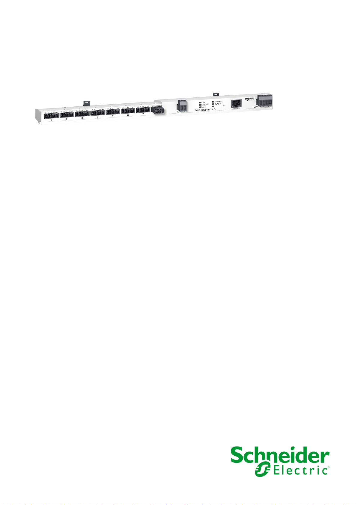
Smartlink SI B
DOCA0123EN-04 09/2020
Smartlink SI B
User Manual
09/2020
DOCA0123EN-04
www.se.com
Page 2

The information provided in this documentation contains general descriptions and/or technical characteristics of the performance of the products contained herein. This documentation is not intended as a
substitute for and is not to be used for determining suitability or reliability of these products for specific user
applications. It is the duty of any such user or integrator to perform the appropriate and complete risk
analysis, evaluation and testing of the products with respect to the relevant specific application or use
thereof. Neither Schneider Electric nor any of its affiliates or subsidiaries shall be responsible or liable for
misuse of the information contained herein. If you have any suggestions for improvements or amendments
or have found errors in this publication, please notify us.
You agree not to reproduce, other than for your own personal, noncommercial use, all or part of this
document on any medium whatsoever without permission of Schneider Electric, given in writing. You also
agree not to establish any hypertext links to this document or its content. Schneider Electric does not grant
any right or license for the personal and noncommercial use of the document or its content, except for a
non-exclusive license to consult it on an "as is" basis, at your own risk. All other rights are reserved.
All pertinent state, regional, and local safety regulations must be observed when installing and using this
product. For reasons of safety and to help ensure compliance with documented system data, only the
manufacturer should perform repairs to components.
When devices are used for applications with technical safety requirements, the relevant instructions must
be followed.
Failure to use Schneider Electric software or approved software with our hardware products may result in
injury, harm, or improper operating results.
Failure to observe this information can result in injury or equipment damage.
© 2020 Schneider Electric. All rights reserved.
2 DOCA0123EN-04 09/2020
Page 3

Table of Contents
Safety Information. . . . . . . . . . . . . . . . . . . . . . . . . . . . . . . . . . . . . . . . . . . . 7
About the Book . . . . . . . . . . . . . . . . . . . . . . . . . . . . . . . . . . . . . . . . . . . . . . 9
Chapter 1 Smartlink System . . . . . . . . . . . . . . . . . . . . . . . . . . . . . . . . . . . . . . . . . . . . 11
Overview . . . . . . . . . . . . . . . . . . . . . . . . . . . . . . . . . . . . . . . . . . . . . . . . . . . . . . . . . . . . . . . .
Chapter 2 Architecture of Smartlink System . . . . . . . . . . . . . . . . . . . . . . . . . . . . . . . . 15
Smartlink SI B Gateway. . . . . . . . . . . . . . . . . . . . . . . . . . . . . . . . . . . . . . . . . . . . . . . . . . . . .
Smartlink Communication System Pre-assembled Cables . . . . . . . . . . . . . . . . . . . . . . . . . .
Acti9 Devices with Ti24 Interface . . . . . . . . . . . . . . . . . . . . . . . . . . . . . . . . . . . . . . . . . . . . .
Acti9 Devices without Ti24 Interface . . . . . . . . . . . . . . . . . . . . . . . . . . . . . . . . . . . . . . . . . . .
PowerTag Wireless Communication Devices . . . . . . . . . . . . . . . . . . . . . . . . . . . . . . . . . . . .
Devices out of the Acti9 Range . . . . . . . . . . . . . . . . . . . . . . . . . . . . . . . . . . . . . . . . . . . . . . .
Devices with Analog Output . . . . . . . . . . . . . . . . . . . . . . . . . . . . . . . . . . . . . . . . . . . . . . . . .
Chapter 3 Technical Characteristics . . . . . . . . . . . . . . . . . . . . . . . . . . . . . . . . . . . . . . 27
Technical Characteristics of the Smartlink SI B Gateway . . . . . . . . . . . . . . . . . . . . . . . . . . .
Technical Characteristics of the Devices with Ti24 Interface . . . . . . . . . . . . . . . . . . . . . . . .
Chapter 4 Sizing the 24 Vdc Power Supply. . . . . . . . . . . . . . . . . . . . . . . . . . . . . . . . . 33
Definition of the 24 Vdc Power Supply . . . . . . . . . . . . . . . . . . . . . . . . . . . . . . . . . . . . . . . . .
Protection Against a 240 Vac Fault on the Smartlink SI B Gateway Channels . . . . . . . . . . .
Electromagnetic Compatibility (EMC) Recommendations . . . . . . . . . . . . . . . . . . . . . . . . . . .
Chapter 5 Installation. . . . . . . . . . . . . . . . . . . . . . . . . . . . . . . . . . . . . . . . . . . . . . . . . . 39
Mounting . . . . . . . . . . . . . . . . . . . . . . . . . . . . . . . . . . . . . . . . . . . . . . . . . . . . . . . . . . . . . . . .
Connection . . . . . . . . . . . . . . . . . . . . . . . . . . . . . . . . . . . . . . . . . . . . . . . . . . . . . . . . . . . . . .
Chapter 6 Connection of Input/Output Channels. . . . . . . . . . . . . . . . . . . . . . . . . . . . . 49
Acti9 Devices with Ti24 Interface . . . . . . . . . . . . . . . . . . . . . . . . . . . . . . . . . . . . . . . . . . . . .
Meters . . . . . . . . . . . . . . . . . . . . . . . . . . . . . . . . . . . . . . . . . . . . . . . . . . . . . . . . . . . . . . . . . .
Volt-Free Low Level Indication Contact . . . . . . . . . . . . . . . . . . . . . . . . . . . . . . . . . . . . . . . . .
Volt-Free Standard Indication Contact . . . . . . . . . . . . . . . . . . . . . . . . . . . . . . . . . . . . . . . . .
Surge Arresters . . . . . . . . . . . . . . . . . . . . . . . . . . . . . . . . . . . . . . . . . . . . . . . . . . . . . . . . . . .
Contactor and Relay (Not in the Acti9 Range) . . . . . . . . . . . . . . . . . . . . . . . . . . . . . . . . . . .
Direct Output Connection . . . . . . . . . . . . . . . . . . . . . . . . . . . . . . . . . . . . . . . . . . . . . . . . . . .
Indirect Output Connection . . . . . . . . . . . . . . . . . . . . . . . . . . . . . . . . . . . . . . . . . . . . . . . . . .
Generating Summary Data Using iOF+SD24, OF+SD24, OF24, or SD24 . . . . . . . . . . . . . .
Analog Input Characteristics and Connection (Recommendation) . . . . . . . . . . . . . . . . . . . .
Recommendation for Cabling . . . . . . . . . . . . . . . . . . . . . . . . . . . . . . . . . . . . . . . . . . . . . . . .
Chapter 7 Getting Started with Smartlink SI B Gateway . . . . . . . . . . . . . . . . . . . . . . . 67
7.1 General Principle to Commission a Smartlink SI B Gateway System . . . . . . . . . . . . . . . . . .
Commissioning Overview . . . . . . . . . . . . . . . . . . . . . . . . . . . . . . . . . . . . . . . . . . . . . . . . . . .
7.2 Commissioning a Smartlink SI B Gateway System with EcoStruxure Power Commission
Software . . . . . . . . . . . . . . . . . . . . . . . . . . . . . . . . . . . . . . . . . . . . . . . . . . . . . . . . . . . . . . . .
Installation of EcoStruxure Power Commission Software . . . . . . . . . . . . . . . . . . . . . . . . . . .
Commissioning with EcoStruxure Power Commission Software. . . . . . . . . . . . . . . . . . . . . .
7.3 Commissioning a Smartlink SI B Gateway with Webpages . . . . . . . . . . . . . . . . . . . . . . . . .
Discovering Smartlink SI B Gateway through Windows Explorer . . . . . . . . . . . . . . . . . . . . .
Login into Webpages. . . . . . . . . . . . . . . . . . . . . . . . . . . . . . . . . . . . . . . . . . . . . . . . . . . . . . .
Webpage Layout . . . . . . . . . . . . . . . . . . . . . . . . . . . . . . . . . . . . . . . . . . . . . . . . . . . . . . . . . .
Firmware Upgrade. . . . . . . . . . . . . . . . . . . . . . . . . . . . . . . . . . . . . . . . . . . . . . . . . . . . . . . . .
Basic Commissioning of PowerTag Wireless Communication Energy Sensors . . . . . . . . . .
Commissioning the Modbus Meters . . . . . . . . . . . . . . . . . . . . . . . . . . . . . . . . . . . . . . . . . . .
Chapter 8 Setting Up Wireless Communication . . . . . . . . . . . . . . . . . . . . . . . . . . . . . 83
Wireless Network Configuration . . . . . . . . . . . . . . . . . . . . . . . . . . . . . . . . . . . . . . . . . . . . . .
Wireless Communication Devices Selection and Configuration . . . . . . . . . . . . . . . . . . . . . .
11
16
19
21
22
23
25
26
28
31
34
36
37
40
46
50
51
52
53
54
57
58
59
60
62
63
68
68
69
70
71
73
74
76
77
78
79
81
84
86
DOCA0123EN-04 09/2020 3
Page 4

Chapter 9 Setting Up Ethernet Communication . . . . . . . . . . . . . . . . . . . . . . . . . . . . . . 89
Ethernet Principle. . . . . . . . . . . . . . . . . . . . . . . . . . . . . . . . . . . . . . . . . . . . . . . . . . . . . . . . . .
Set Up and Ethernet Addressing Mode . . . . . . . . . . . . . . . . . . . . . . . . . . . . . . . . . . . . . . . . .
Ethernet Settings . . . . . . . . . . . . . . . . . . . . . . . . . . . . . . . . . . . . . . . . . . . . . . . . . . . . . . . . . .
IP Configuration . . . . . . . . . . . . . . . . . . . . . . . . . . . . . . . . . . . . . . . . . . . . . . . . . . . . . . . . . . .
IP Network Services. . . . . . . . . . . . . . . . . . . . . . . . . . . . . . . . . . . . . . . . . . . . . . . . . . . . . . . .
Smartlink SI B Gateway Function . . . . . . . . . . . . . . . . . . . . . . . . . . . . . . . . . . . . . . . . . . . . .
Chapter 10 Setting Up Modbus Communication (Gateway Function). . . . . . . . . . . . . . . 97
Modbus Master Principle . . . . . . . . . . . . . . . . . . . . . . . . . . . . . . . . . . . . . . . . . . . . . . . . . . . .
Possible Architecture . . . . . . . . . . . . . . . . . . . . . . . . . . . . . . . . . . . . . . . . . . . . . . . . . . . . . . .
Setup . . . . . . . . . . . . . . . . . . . . . . . . . . . . . . . . . . . . . . . . . . . . . . . . . . . . . . . . . . . . . . . . . . .
Gateway Features . . . . . . . . . . . . . . . . . . . . . . . . . . . . . . . . . . . . . . . . . . . . . . . . . . . . . . . . .
Modbus Port Settings. . . . . . . . . . . . . . . . . . . . . . . . . . . . . . . . . . . . . . . . . . . . . . . . . . . . . . .
Chapter 11 System Settings Configuration . . . . . . . . . . . . . . . . . . . . . . . . . . . . . . . . . . . 105
General Network Settings . . . . . . . . . . . . . . . . . . . . . . . . . . . . . . . . . . . . . . . . . . . . . . . . . . .
Modbus TCP/IP Filtering . . . . . . . . . . . . . . . . . . . . . . . . . . . . . . . . . . . . . . . . . . . . . . . . . . . .
Email Service . . . . . . . . . . . . . . . . . . . . . . . . . . . . . . . . . . . . . . . . . . . . . . . . . . . . . . . . . . . . .
User Management . . . . . . . . . . . . . . . . . . . . . . . . . . . . . . . . . . . . . . . . . . . . . . . . . . . . . . . . .
Alarms . . . . . . . . . . . . . . . . . . . . . . . . . . . . . . . . . . . . . . . . . . . . . . . . . . . . . . . . . . . . . . . . . .
Devices . . . . . . . . . . . . . . . . . . . . . . . . . . . . . . . . . . . . . . . . . . . . . . . . . . . . . . . . . . . . . . . . .
Chapter 12 Monitoring, Control, and Diagnostics Webpages . . . . . . . . . . . . . . . . . . . . . 123
Monitoring and Control Page . . . . . . . . . . . . . . . . . . . . . . . . . . . . . . . . . . . . . . . . . . . . . . . . .
Alarms Page. . . . . . . . . . . . . . . . . . . . . . . . . . . . . . . . . . . . . . . . . . . . . . . . . . . . . . . . . . . . . .
General Diagnostics . . . . . . . . . . . . . . . . . . . . . . . . . . . . . . . . . . . . . . . . . . . . . . . . . . . . . . .
Communication Diagnostics. . . . . . . . . . . . . . . . . . . . . . . . . . . . . . . . . . . . . . . . . . . . . . . . . .
Chapter 13 Modbus Registers Tables. . . . . . . . . . . . . . . . . . . . . . . . . . . . . . . . . . . . . . . 131
13.1 General Description of Modbus Tables . . . . . . . . . . . . . . . . . . . . . . . . . . . . . . . . . . . . . . . . .
Overview . . . . . . . . . . . . . . . . . . . . . . . . . . . . . . . . . . . . . . . . . . . . . . . . . . . . . . . . . . . . . . . .
Modbus Table Format and Data Types . . . . . . . . . . . . . . . . . . . . . . . . . . . . . . . . . . . . . . . . .
13.2 Summary and Detailed Modbus Tables . . . . . . . . . . . . . . . . . . . . . . . . . . . . . . . . . . . . . . . . .
System Modbus Table . . . . . . . . . . . . . . . . . . . . . . . . . . . . . . . . . . . . . . . . . . . . . . . . . . . . . .
Summary of Digital Channels 1 to 7. . . . . . . . . . . . . . . . . . . . . . . . . . . . . . . . . . . . . . . . . . . .
Details of Digital Channels 1 to 7 . . . . . . . . . . . . . . . . . . . . . . . . . . . . . . . . . . . . . . . . . . . . . .
Analog Inputs . . . . . . . . . . . . . . . . . . . . . . . . . . . . . . . . . . . . . . . . . . . . . . . . . . . . . . . . . . . . .
PowerTag Wireless Communication Energy Sensors Modbus Tables . . . . . . . . . . . . . . . . .
Embedded Configuration Registers . . . . . . . . . . . . . . . . . . . . . . . . . . . . . . . . . . . . . . . . . . . .
13.3 Modbus Tables for Connected Devices . . . . . . . . . . . . . . . . . . . . . . . . . . . . . . . . . . . . . . . . .
iOF+SD24 Indication Auxiliary . . . . . . . . . . . . . . . . . . . . . . . . . . . . . . . . . . . . . . . . . . . . . . . .
OF+SD24 Indication Auxiliary . . . . . . . . . . . . . . . . . . . . . . . . . . . . . . . . . . . . . . . . . . . . . . . .
iEM Meters or Meter with Pulse Output (IEC 62053-31 Standard) . . . . . . . . . . . . . . . . . . . .
iACT24 Auxiliary for iCT Contactor . . . . . . . . . . . . . . . . . . . . . . . . . . . . . . . . . . . . . . . . . . . .
iATL24 Auxiliary for iTL Impulse Relay . . . . . . . . . . . . . . . . . . . . . . . . . . . . . . . . . . . . . . . . .
Contactor and Relay (Not in the Acti9 Range) . . . . . . . . . . . . . . . . . . . . . . . . . . . . . . . . . . . .
Acti9 RCA iC60 Remote Control with Ti24 Interface . . . . . . . . . . . . . . . . . . . . . . . . . . . . . . .
Acti9 Reflex iC60 Integrated Control Circuit Breaker With Ti24 Interface . . . . . . . . . . . . . . .
Chapter 14 Troubleshooting . . . . . . . . . . . . . . . . . . . . . . . . . . . . . . . . . . . . . . . . . . . . . . 167
Common Problems . . . . . . . . . . . . . . . . . . . . . . . . . . . . . . . . . . . . . . . . . . . . . . . . . . . . . . . .
Appendices . . . . . . . . . . . . . . . . . . . . . . . . . . . . . . . . . . . . . . . . . . . . . . . . . . . . . .
Appendix A Details of Modbus Functions . . . . . . . . . . . . . . . . . . . . . . . . . . . . . . . . . . . . 171
Modbus TCP/IP Functions . . . . . . . . . . . . . . . . . . . . . . . . . . . . . . . . . . . . . . . . . . . . . . . . . . .
Modbus TCP/IP Exception Codes . . . . . . . . . . . . . . . . . . . . . . . . . . . . . . . . . . . . . . . . . . . . .
Function 8: Modbus Diagnostics . . . . . . . . . . . . . . . . . . . . . . . . . . . . . . . . . . . . . . . . . . . . . .
90
91
93
94
95
96
98
100
101
102
103
106
109
110
113
115
117
124
126
127
128
132
133
135
138
139
141
144
149
151
156
158
159
160
161
162
163
164
165
166
167
169
172
174
175
4 DOCA0123EN-04 09/2020
Page 5

Function 43-14: Read Device Identification. . . . . . . . . . . . . . . . . . . . . . . . . . . . . . . . . . . . . .
Function 43–15: Read Date and Time. . . . . . . . . . . . . . . . . . . . . . . . . . . . . . . . . . . . . . . . . .
Function 43-16: Write Date and Time . . . . . . . . . . . . . . . . . . . . . . . . . . . . . . . . . . . . . . . . . .
Function 100–4: Read n Non-Adjacent Words . . . . . . . . . . . . . . . . . . . . . . . . . . . . . . . . . . .
177
179
180
181
Appendix B Data Availability . . . . . . . . . . . . . . . . . . . . . . . . . . . . . . . . . . . . . . . . . . . . . 183
Data Availability . . . . . . . . . . . . . . . . . . . . . . . . . . . . . . . . . . . . . . . . . . . . . . . . . . . . . . . . . . .
183
Appendix C Reset of Smartlink SI B Gateway . . . . . . . . . . . . . . . . . . . . . . . . . . . . . . . . 187
Description. . . . . . . . . . . . . . . . . . . . . . . . . . . . . . . . . . . . . . . . . . . . . . . . . . . . . . . . . . . . . . .
187
DOCA0123EN-04 09/2020 5
Page 6

6 DOCA0123EN-04 09/2020
Page 7
Safety Information
Important Information
NOTICE
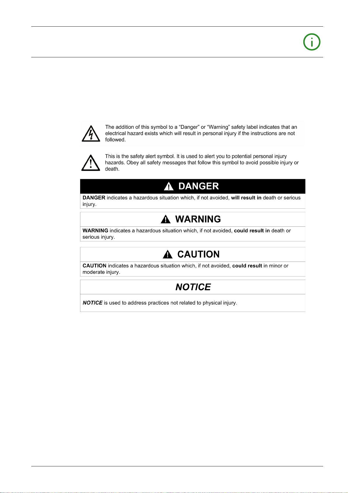
Read these instructions carefully, and look at the equipment to become familiar with the device before
trying to install, operate, service, or maintain it. The following special messages may appear throughout
this documentation or on the equipment to warn of potential hazards or to call attention to information that
clarifies or simplifies a procedure.
PLEASE NOTE
Electrical equipment should be installed, operated, serviced, and maintained only by qualified personnel.
No responsibility is assumed by Schneider Electric for any consequences arising out of the use of this
material.
A qualified person is one who has skills and knowledge related to the construction and operation of
electrical equipment and its installation, and has received safety training to recognize and avoid the
hazards involved.
DOCA0123EN-04 09/2020 7
Page 8
CYBERSECURITY SAFETY NOTICE
POTENTIAL COMPROMISE OF SYSTEM AVAILABILITY, INTEGRITY, AND CONFIDENTIALITY
Change default passwords at first use to help prevent unauthorized access to device settings,
controls, and information.
Disable unused ports/services and default accounts to help minimize pathways for malicious
attackers.
Place networked devices behind multiple layers of cyber defenses (such as firewalls, network
segmentation, and network intrusion detection and protection).
Use cybersecurity best practices (for example, least privilege, separation of duties) to help prevent
unauthorized exposure, loss, modification of data and logs, or interruption of services.
Failure to follow these instructions can result in death, serious injury, or equipment damage.
WARNING
8 DOCA0123EN-04 09/2020
Page 9
At a Glance
Document Scope
Validity Note
Online Information
About the Book
The purpose of this manual is to provide users, installers, and maintenance personnel with the technical
information necessary to install and use the Smartlink SI B communication system.
The Smartlink SI B communication system can be easily integrated into any building management
architecture.
It combines command and control, metering and protection functions designed for energy efficiency
solutions. Based on the Modbus protocol, the Smartlink SI B communication system allows switchboard
data to be exchanged in real time with a supervision system or a PLC.
This system's pre-wired cables can save time and prevent wiring errors during installation.
The information contained in this guide is likely to be updated at any time. Schneider Electric strongly
recommends that you have the most recent and up-to-date version available on
www.se.com/ww/en/download
The technical characteristics of the devices described in this guide also appear online. To access the
information online, go to the Schneider Electric home page at
.
www.se.com
.
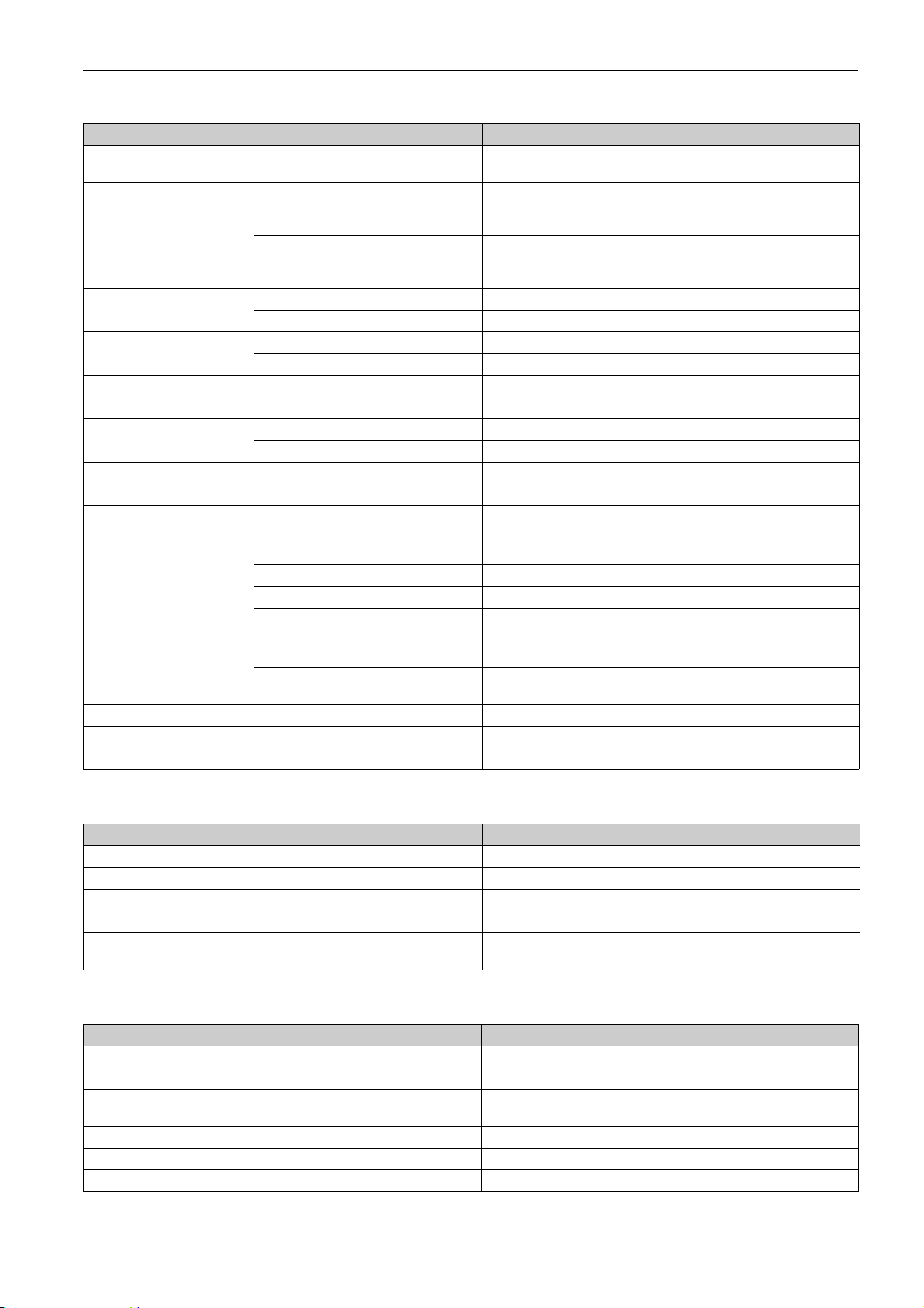
Related Documents
Title of Documentation Reference Number
Smartlink Ethernet Communication System – User Manual
Smartlink Modbus Communication System – User Manual
iEM3000 Series - Energy Meters – User Manual
PM3200 Series – Power Meters – User Manual
Communication System Diagnostics – User Manual
Smartlink SI B Gateway – Release Note
PowerLogic EGX300 Ethernet Gateway – User Guide
EcoStruxure Power Commission – Installation Guide
Smartlink SI B Gateway – Instruction Sheet
Smartlink Modbus Gateway – Instruction Sheet
iACT24 - Low-level Control and Indication Auxiliary for iCT Contactors – Instruction Sheet
iATL24 - Low-level Control and Indication Auxiliary for iTL Impulse Relays – Instruction Sheet
RCA iC60 Remote Controls – Instruction Sheet
Watt-hour Meter - iEM2000T – Instruction Sheet
iEM3100 Series 63 A Watt-hour Meter (MID) – Instruction Sheet
iEM3200 Series 1 A/5 A Watt-hour Meter (MID) – Instruction Sheet
iEM3300 and iEM3350 125 A Watt-hour Meter (MID) – Instruction Sheet
iEM3310 125 A Watt-hour Meter (MID) – Instruction Sheet
PM3250 – PM3255 – Power Meter – Instruction Sheet
PowerTag M63 Energy Sensor – Instruction Sheet
PowerTag P63 Energy Sensor – Instruction Sheet
PowerTag F63 Energy Sensor – Instruction Sheet
PowerTag M250 Energy Sensor – Instruction Sheet
PowerTag M630 Energy Sensor – Instruction Sheet
RCA iC60 Remote Control - iC60 Circuit Breakers – Reference Manual
DOCA0073EN
DOCA0004EN
DOCA0005EN
DOCA0006EN
DOCA0042EN
DOCA0181EN
63230-319-216
DOCA0134EN
NVE12086
S1B33423
S1B3342101
S1B3342201
S1A4079001
S1A89364
NHA15789
NHA15801
HRB91204
HRB91202
S1B46607
EAV31628
QGH78639
QGH78642
QGH46815
QGH46820
A9MA01EN
DOCA0123EN-04 09/2020 9
Page 10

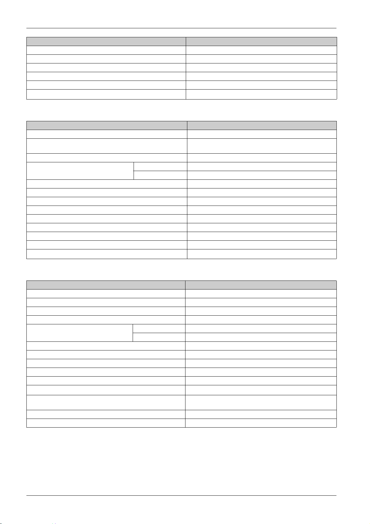
Title of Documentation Reference Number
Reflex iC60 Integrated Control Circuit Breaker - iC60 Circuit Breakers – Reference Manual
Reflex iC60 - Integrated Remote Control Circuit Breakers – Reference Manual
Smartlink Device – Catalogue Page
A9MA03EN
S1B8674701
CA908033E
You can download these technical publications and other technical information from our website at
https://www.se.com/en/download
.
Trademark Notice
All trademarks are owned by Schneider Electric Industries SAS or its affiliated companies.
10 DOCA0123EN-04 09/2020
Page 11

Overview
Introduction
Smartlink SI B
Smartlink System
DOCA0123EN-04 09/2020
Smartlink System
Chapter 1
Smartlink System
The Smartlink system is used to control and monitor the final distribution boards to any supervision system.
Modular devices in the Smartlink system is used to monitor, measure, and control electrical distribution
boards via a Modbus serial line or Modbus TCP/IP communication network.
The Smartlink system concentrates the data from electrical distribution boards in real time, thus
contributing to achieve energy efficiency targets.
The Smartlink system collects data from any meter (including kilowatt-hour, water, air, gas, or steam
meters).
This system consists of:
Smartlink SI B gateway and the test kit.
iOF+SD24, OF+SD24, iOF/SD24 indication auxiliaries.
iACT24 and iATL24 auxiliaries for contactors and impulse relays.
Acti9 RCA iC60 remote control module with Ti24 interface.
Acti9 Reflex iC60 integrated control circuit breaker with Ti24 interface.
iEM2000T, iEM3110, iEM3155, iEM3210, iEM3255, iEM3310, iEM3350, and iEM3355 pulse meters
and Modbus meters.
PowerTag energy sensors such as:
PowerTag M63 (for iC60 offer)
PowerTag P63 (for DT40 and iC40 offers)
PowerTag F63 (for other devices such as VigiBlock and specific installations)
PowerTag M250/M630 (for ComPact NSX, ComPact INS, and ComPact INV)
The PowerTag energy sensors are wireless devices that are directly mounted on a protective device
and are connected to Smartlink SI B gateway through a wireless communication. The circuit breaker
auxiliary allows you to monitor and control the devices and collects not only energy, but also power and
alarm events on the voltage loss. PowerTag energy sensors are mounted upstream or downstream of
the device.
Pre-wired cables.
This system offers the following advantages and services:
Calculation functions.
Telemetering applications.
Monitor load unbalance.
Monitor power and voltage loss.
Alarm temperature, humidity, and luminescence.
Energy management and regulations.
Scheduled control of electrical distribution with any building systems.
The Smartlink system is an open system:
Smartlink SI B gateway can be used as a standard I/O distributed module.
Smartlink SI B gateway is equipped with seven digital channels. Each channel is represented by a Ti24
interface consisting of:
Two power supply terminals: 0 V and 24 Vdc
Two 24 Vdc logic inputs (I1 and I2)
One 24 Vdc logic output (Q)
Each Ti24 interface is compatible with Miniconnect Phoenix standard connectors (at intervals of
3.81 mm) or equivalent.
Smartlink SI B gateway is equipped with one analog channel having:
Two power supply terminals: 0 V and 24 Vdc
Two analog inputs (4...20 mA or 0...10 V)
DOCA0123EN-04 09/2020 11
Page 12
Smartlink System
Smartlink SI B gateway is compatible with any type of counter (pulse output) compliant with standard
IEC 62053-21 (minimum pulse width of 30 ms):
The pulse weight must be configured (written in a Modbus register).
Smartlink SI B gateway calculates consumption and flow.
Smartlink SI B gateway is compatible with any type of device equipped with low-level inputs and outputs
(24 Vdc).
The Smartlink system is simple to use:
The pre-wired cables of the Smartlink system reduce complexity and wiring time by allowing connection
on a Smartlink SI B gateway of the Smartlink system components and 24 Vdc compatible products.
The functions of the Smartlink system can be created by sending messages (Modbus protocol) to
Smartlink devices (Modbus slave or Ethernet server) that act on devices via Ti24 interfaces.
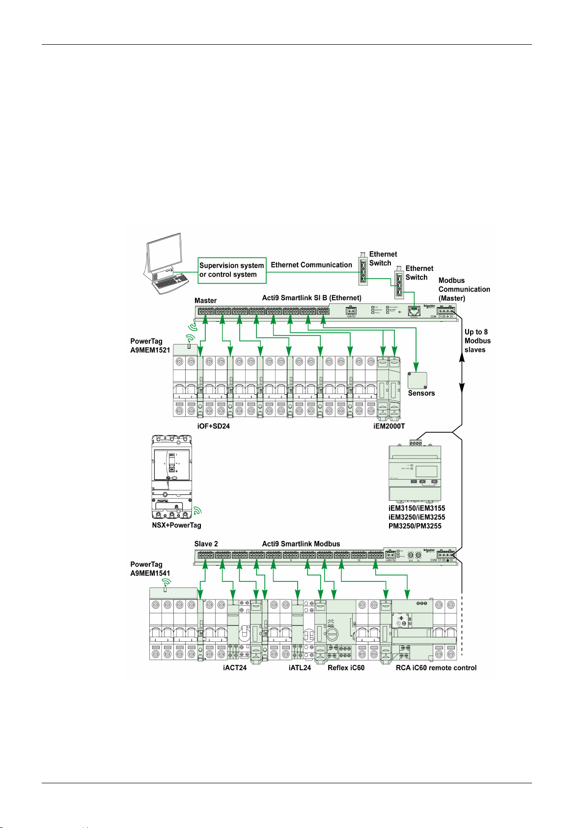
Smartlink SI B Communication System Block Diagram
12
The Smartlink SI B communication system can manage a gateway function (Modbus TCP/IP to Modbus
RS485). It can support up to eight Modbus RS485 slave devices (address from 1 to 149). The default
address of the Modbus master port is 255.
The Smartlink SI B communication system also manages webpage to configure the settings or to monitor
and control the devices.
DOCA0123EN-04 09/2020
Page 13
Smartlink System
DANGER
HAZARD OF ELECTRIC SHOCK, EXPLOSION, OR ARC FLASH
It is recommended not to use Smartlink SI B gateway to remotely control the circuits or loads requiring
visual attendance.
Failure to follow these instructions will result in death or serious injury.
WARNING
POTENTIAL COMPROMISE OF SYSTEM AVAILABILITY, INTEGRITY, AND CONFIDENTIALITY
Change the default passwords to help prevent unauthorized access to device settings and information.
Failure to follow these instructions can result in death, serious injury, or equipment damage.
DOCA0123EN-04 09/2020 13
Page 14

Smartlink System
14
DOCA0123EN-04 09/2020
Page 15
Smartlink SI B
Architecture of Smartlink System
DOCA0123EN-04 09/2020
Architecture of Smartlink System
Chapter 2
Architecture of Smartlink System
What Is in This Chapter?
This chapter contains the following topics:
Smartlink SI B Gateway 16
Smartlink Communication System Pre-assembled Cables 19
Acti9 Devices with Ti24 Interface 21
Acti9 Devices without Ti24 Interface 22
PowerTag Wireless Communication Devices 23
Devices out of the Acti9 Range 25
Devices with Analog Output 26
Topic Page
DOCA0123EN-04 09/2020 15
Page 16
Architecture of Smartlink System
Smartlink SI B Gateway
Introduction
The Smartlink SI B gateway has seven digital channels (24 Vdc) and one analog channel (4...20 mA or
0...10 Vdc) and can be connected to the devices in the Acti9 range equipped with a Ti24 interface. The
data can be transmitted from the Smartlink SI B gateway to a PLC or a supervision system via a
Modbus TCP/IP protocol.
The Smartlink SI B gateway channels can also be used to transmit standardized I/O. The Smartlink SI B
gateway can also therefore communicate with devices (not in the Acti9 range) with or without a Ti24 link.
The devices which can be connected to the Smartlink SI B gateway include:
Acti9 products: control switch for iACT24 contactors and iATL24 impulse relays, iC60 iOF+SD24
indication auxiliary, C60 OF+SD24 indication auxiliary, RCA iC60 remote control with Ti24 interface,
Reflex iC60 integrated control circuit breaker with Ti24 interface.
Meters: iEM2000T or other meters (Schneider Electric or other manufacturers) in compliance with IEC
62053-21 (minimum pulse 30 ms).
Any product (not in the Acti9 range) that has command and control information: 2 discrete 24 V outputs
and 1 discrete 24 V input.
PowerTag energy sensors.
Any product using analog output (4...20 mA or 0...10 V).
The Smartlink SI B gateway is an intermediary between the supervisor and various electrical appliances.
It can therefore be used to retrieve and process data received from devices and also control them. The
functions available depend on the type of connected devices.
The functions of Smartlink SI B gateway are described in Smartlink SI B Function
(see page 96)
.
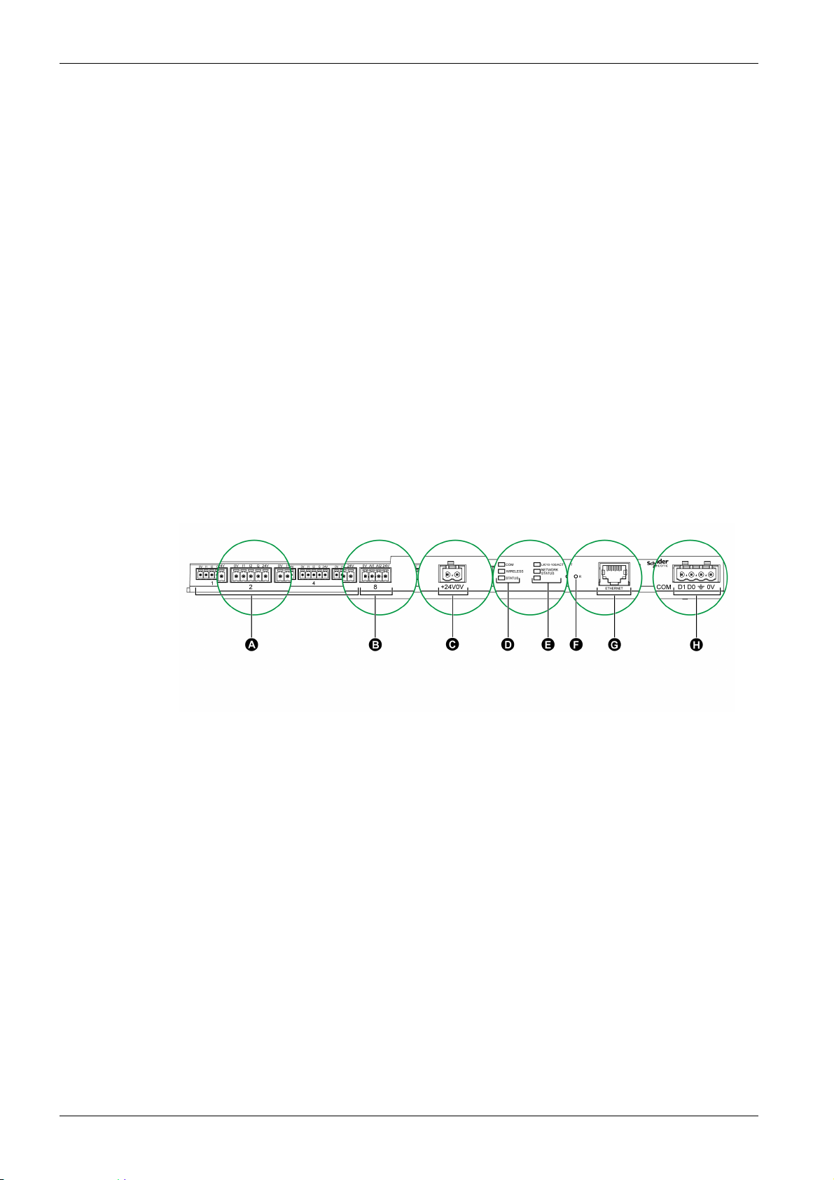
Description
A 7 digital input/output channels
B 1 analog channel with two inputs
C 1 x 24 V power connector
D Status LEDs (including Wireless LED)
E Ethernet LEDs
F Reset button
G Ethernet communication port
H 1 Modbus connector: 4-way
Smartlink SI B Gateway Acting as a PowerTag Concentrator
The PowerTag auxiliaries provide compact and high density metering solution with rich and accurate data
for building systems (that can send energy, power, current, voltage, and power factor to Smartlink
concentrator every 5 seconds). Tagging a circuit breaker with PowerTag allows you to monitor any
electrical device with high flexibility (for example, you can add PowerTag energy sensors after the lastminute changes in the distribution board).
The PowerTag energy sensors provide an advanced alarm on load level of each phase to monitor and
balance the loads, and sends an alarm if the electrical device is down.
The Smartlink SI B gateway behaves as a data concentrator to collect information from digital, analog,
wireless auxiliaries, and downstream Modbus devices. The Smartlink SI B gateway provides monitoring
and control of the digital switchboard over Modbus TCP for upstream software and via embedded
webpages. The addition of new wireless auxiliaries provides affordable metering with panel size
optimization.
16
DOCA0123EN-04 09/2020
Page 17
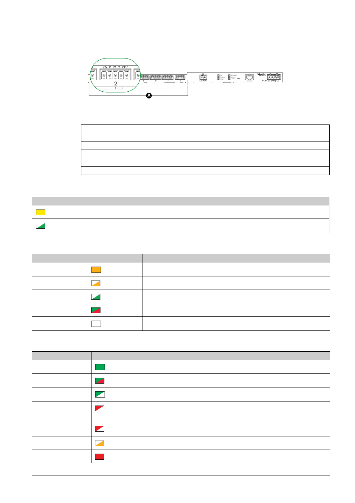
Digital Input/Output Channels
The figure below shows the terminals for each channel.
A Channels from 1 to 7
Description of terminals for each channel (Ti24 interface):
Terminal Description
24V 24 V of the 24 Vdc power supply
Q Control output
I2 Input number 2
I1 Input number 1
0V 0 V of the 24 Vdc power supply
Communication LED
Architecture of Smartlink System
COM LED Description
Yellow: During communication with the Modbus serial port, the LED is Off if there is no Modbus communication
Blinking green: While pressing the reset button between 5 and 10 seconds, the IP settings are reconfigured to
DHCP mode
Wireless Status LED
Operating Mode WIRELESS LED Description
Initialization
Startup Blinking amber: Looking for wireless device
Operation Flash green every five seconds: Networking complete (normal operation)
Degraded
Disabled
Solid amber: Not configured
Blink green and red (one second): Downgraded in Boot mode
No light: Wireless disabled
Status LED
Operating Mode STATUS LED Description
Initialization / Operation Green light: Device operates normally
Start-up
Reset (level 1)
Reset (level 2) Red blink (Fast, 2 blinks/sec): While pressing the Reset button for more than10 seconds.
Duplicate IP address Red blink (1 blink per second): System has detected duplicate IP address. Check and
Degraded Flashing orange light: Power supply of the product is degraded
Failure Red light: Out of service or hardware failure
DOCA0123EN-04 09/2020 17
Alternate green and red light every second: Device is starting
Green blink: Reset button acknowledgment (pressed between 5 to 10 seconds). IP
settings are reconfigured to DHCP mode.
The LED stops blinking after the device restarts. Do not switch off the device until the LED
stops blinking in RED for at least 30 seconds, as the product restarts.
change the IP address of the Smartlink SI B gateway.
Page 18
Architecture of Smartlink System
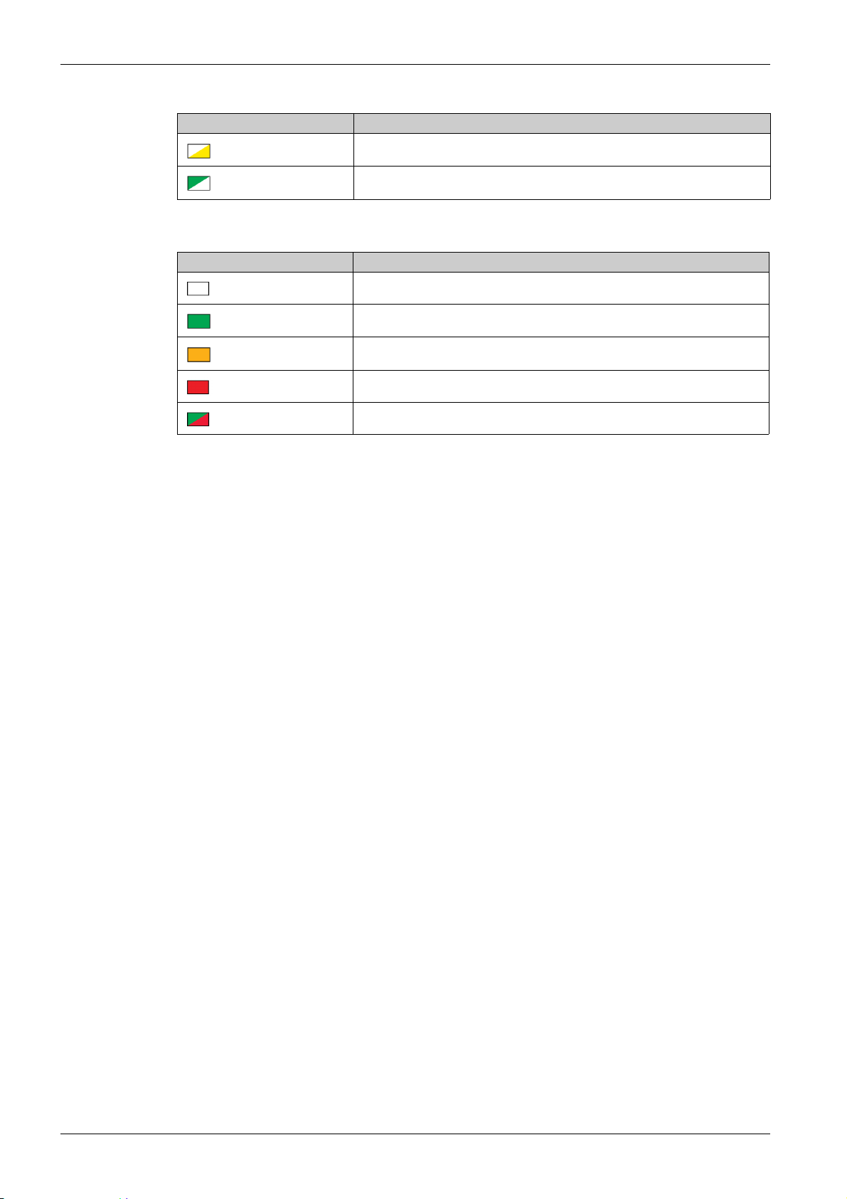
Ethernet Status LED
LK/10-100/ACT LED Description
Network Status LED
NETWORK STATUS LED Description
Alternate yellow and white: Activity at 10 Mbps
Alternate green and white: Activity at 100 Mbps
No light: No power, invalid IP address
Green: Connected, valid IP address
Amber: Factory setting IPv4 address
Red: Duplicated IP address/IP error
Flashing green and red light: Self-test
18
DOCA0123EN-04 09/2020
Page 19
Architecture of Smartlink System
Smartlink Communication System Pre-assembled Cables
Description
The Smartlink communication pre-assembled cables are a quick way to connect all the Smartlink
communication system components and compatible products (24 Vdc) to the Smartlink SI B gateway
channels.
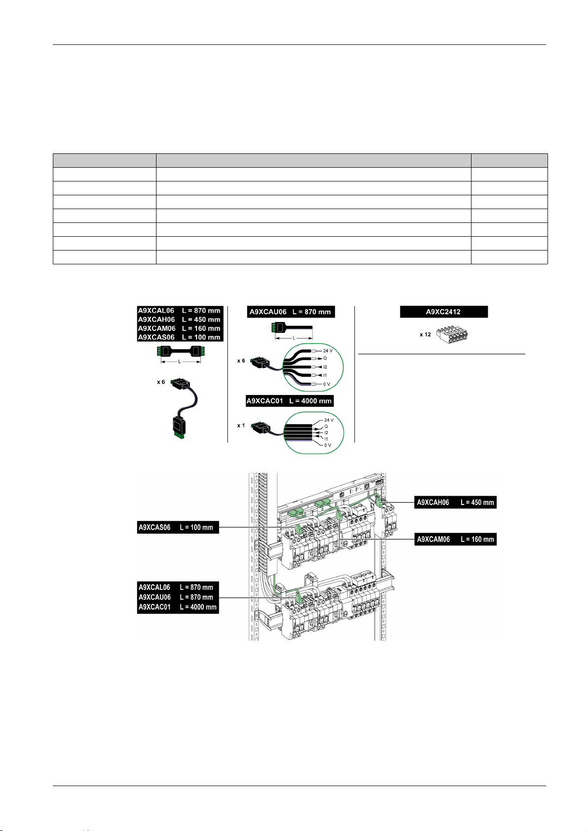
The pre-assembled cables are:
Product Reference Description Length (mm)
A9XCAS06 Set of six pre-assembled cables with two Ti24 connectors 100
A9XCAM06 Set of six pre-assembled cables with two Ti24 connectors 160
A9XCAL06 Set of six pre-assembled cables with two Ti24 connectors 870
A9XCAH06 Set of six pre-assembled cables with two Ti24 connectors 450
A9XCAU06 Set of six pre-assembled cables with one Ti24 connector 870
A9XCAC01 One pre-assembled cable with one Ti24 connector 4,000
A9XC2412 Set of 12 connectors with 5-pin spring -
Each Ti24 interface (I/O channel) is compatible with Miniconnect Phoenix standard connectors (at intervals
of 3.81 mm) or equivalent.
NOTE: The connectors in each pre-assembled cable have a flat surface where a self-adhesive label can
be placed to identify the channel number used.
Self-adhesive labels are not supplied by Schneider Electric.
DOCA0123EN-04 09/2020 19
Page 20
Architecture of Smartlink System
NOTE:
Do not connect two wires in each of the Ti24 connector terminals (A9XC2412).
Do not connect a wire with cable end in each of the Ti24 connector terminals.
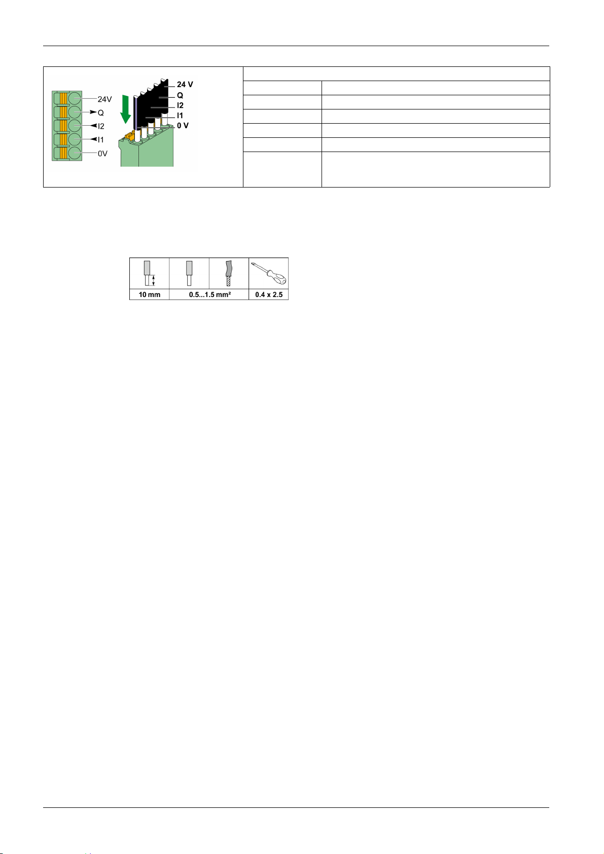
The following figure gives the characteristics of cables that can be used with the A9XC2412 connector:
Description of the Connector at the Ti24 Interface End
Terminal Description
24 V 24 V of the 24 Vdc power supply
Q Control output
I2 Input number 2
I1 Input number 1
0 V 0 V of the 24 Vdc power supply
20
DOCA0123EN-04 09/2020
Page 21
Acti9 Devices with Ti24 Interface
Description
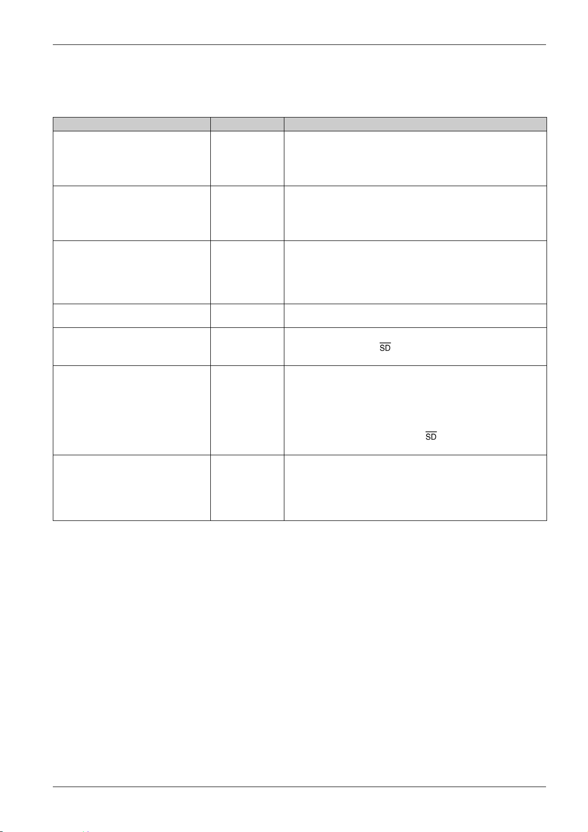
Devices that can be connected to the Smartlink SI B gateway are listed in the table below:
Device Product Reference Description
iACT24 auxiliary for iCT contactor A9C15924 The iACT24 auxiliary:
Can be used to control a contactor (iCT) via its Y1, Y2, and Y3 inputs.
The Y3 (24 Vdc) input can be controlled by one of the Smartlink SI B
gateway channels.
Is used to find out the contactor status (O/C status).
iATL24 auxiliary for iTL contactor A9C15424 The iATL24 auxiliary:
Can be used to control an (iTL) impulse relay via its Y1, Y2, and Y3
inputs. The Y3 (24 Vdc) input can be controlled by one of the
Smartlink SI B gateway channels.
Is used to find out the impulse relay status (O/C status).
iOF/SD24 indication auxiliary for iC60 and
RCBO
iOF+SD24 indication auxiliary for iC60,
iC65, MCB, and iDPN
OF+SD24 indication auxiliary for C60,
C120, C60H-DC, and iDPN circuit breakers
Acti9 RCA iC60 remote control with Ti24
interface
Acti9 Reflex iC60 integrated control circuit
breaker with Ti24 interface
A9A19804 OF24 allows you to monitor the Open/Close status of the breaker. This is
chosen mechanically at device level. Based on your choice, you will
configure the OF24 object on input.
SD24 allows you to monitor the Trip/No Trip status of the breaker. This is
chosen mechanically at device level. Based on your choice, you will
configure the SD24 object on input.
A9A26897 The iOF+SD24 indication auxiliary is used to find out the status of a iC60,
iC65 (OF and states) and iDPN circuit breaker (sold in China).
A9N26899 The OF+SD24 indication auxiliary is used to find out the status of a C60,
C120, C60H-DC (OF and ) and iDPN circuit breaker (sold in all the
countries except China).
A9C7012• The Acti9 RCA iC60 remote control:
Should have a Ti24 interface (with product references A9C70122 and
A9C70124).
Can be used to control an iC60 circuit breaker via input Y3 of its Ti24
interface. Input Y3 (24 Vdc) can be controlled by one of the
Smartlink SI B gateway channels.
Can be used to find out the OF and status of the circuit breaker
associated with the Acti9 RCA iC60 remote control.
A9C6•••• The Acti9 Reflex iC60 integrated control circuit breaker:
Should have a Ti24 interface (with product references A9C6••••).
Can allow the device to be controlled via input Y3 of its Ti24 interface.
The Y3 (24 Vdc) input can be controlled by one of the Smartlink SIB
gateway channels.
Can be used to communicate its O/C and auto/OFF status.
Architecture of Smartlink System
NOTE: All the devices in the above table can be connected to channel N (1 ≤ N ≤ 7) of the Smartlink SI B
gateway with A9XCAS06 pre-wired cable (or A9XCAM06 or A9XCAL06 or A9XCAH06).
DOCA0123EN-04 09/2020 21
Page 22
Architecture of Smartlink System
Acti9 Devices without Ti24 Interface
Description
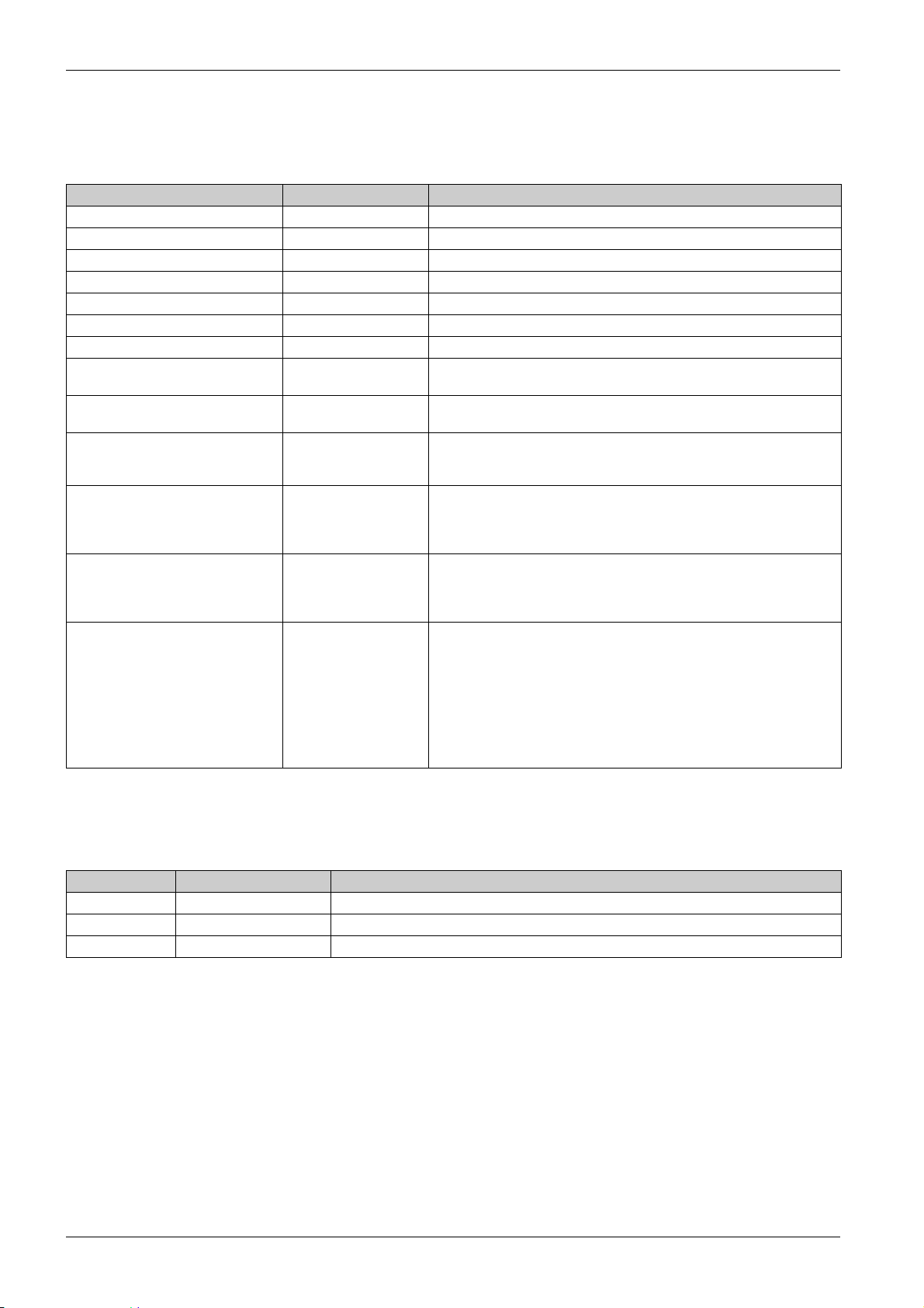
Devices that can be connected to the Smartlink SI B gateway are listed in the table below:
Designation Product Reference Description
iEM2000T A9MEM2000T Single-phase energy meter without display
iEM3110 A9MEM3110 Three-phase energy meter with display
iEM3155 A9MEM3155 Three-phase energy meter with display
iEM3210 A9MEM3210 Three-phase energy meter with display
iEM3255 A9MEM3255 Three-phase energy meter with display
iEM3310 A9MEM3310 Three-phase energy meter with display
iEM3355 A9MEM3355 Three-phase energy meter with display
iPRD (Type 2) A9L••••1 Withdrawable surge arresters with remote indication contact
iPRD65r/iPRD40r/iPRD20r/iPRD8r
iPRD 40r PV (Type 2) A9L40271
A9L40281
iPRF1 12.5r (Type 1 + Type 2;
Type B+C)
PRD1 25r (Type 1 + Type 2) 16329
PRD1 Master (Type 1) 16360
iQuick PRD (Type 2) A9L16292
A9L16632
A9L16633
A9L16634
16330
16331
16332
16361
16362
16363
A9L16293
A9L16294
A9L16295
A9L16296
A9L16297
A9L16298
A9L16299
A9L16300
Withdrawable surge arresters with remote indication contact
Monobloc surge arresters with remote indication contact
Withdrawable surge arresters with remote indication contact
Withdrawable surge arresters with remote indication contact
Withdrawable surge arresters with integrated backup MCB and remote
indication contact
NOTE: The connection of these devices can be done with a pre-wired cable: molded connector (at
Smartlink SI B gateway end), and with five wires (at device end).
The table below describes products that need a low level interface relay in order to be connected to
Smartlink SI B gateway:
Designation Product Reference Description
IH, IHP see catalog Timer switches with RBN type low level relays or equivalent
IC see catalog Light sensitive switches with RBN type low level relays or equivalent
TH, THP see catalog Thermostats with RBN type low level relays or equivalent
22
DOCA0123EN-04 09/2020
Page 23

PowerTag Wireless Communication Devices
Description
Wireless communication devices that can be connected to the Smartlink SI B gateway are listed in the
following table:
Designation Product Reference Description
PowerTag M63 Wireless Communication Energy
Sensor 1P
PowerTag M63 Wireless Communication Energy
Sensor 1P+N Top
PowerTag M63 Wireless Communication Energy
Sensor 1P+N Bottom
PowerTag M63 Wireless Communication Energy
Sensor 3P
PowerTag M63 Wireless Communication Energy
Sensor 3P+N Top
PowerTag M63 Wireless Communication Energy
Sensor 3P+N Bottom
PowerTag P63 Wireless Communication Energy
Sensor 1P+N Top
PowerTag P63 Wireless Communication Energy
Sensor 1P+N Bottom
PowerTag P63 Wireless Communication Energy
Sensor 1P+N Bottom
PowerTag P63 Wireless Communication Energy
Sensor 3P+N Top
PowerTag P63 Wireless Communication Energy
Sensor 3P+N Bottom
PowerTag F63 Wireless Communication Energy
Sensor 1P+N
PowerTag F63 Wireless Communication Energy
Sensor 3P+N
PowerTag M250 Wireless Communication
Energy Sensor 3P
PowerTag M250 Wireless Communication
Energy Sensor 4P
PowerTag M630 Wireless Communication
Energy Sensor 3P
PowerTag M630 Wireless Communication
Energy Sensor 4P
A9MEM1520 One-phase wireless communication energy sensor (installation on
top or bottom of a protective device).
A9MEM1521 One-phase and neutral wireless communication energy sensor
(installation on top of a protective device).
A9MEM1522 One-phase and neutral wireless communication energy sensor
(installation on bottom of a protective device).
A9MEM1540 Three-phase wireless communication energy sensor (installation
on top or bottom of a protective device).
A9MEM1541 Three-phase and neutral wireless communication energy sensor
(installation on top of a protective device).
A9MEM1542 Three-phase and neutral wireless communication energy sensor
(installation on bottom of a protective device).
A9MEM1561 One-phase and neutral wireless communication energy sensor
(installation on top of a protective device).
A9MEM1562 One-phase and neutral wireless communication energy sensor
(installation on bottom of a protective device).
A9MEM1563 One-phase and neutral wireless communication energy sensor
(installation on bottom of a protective device).
A9MEM1571 Three-phase and neutral wireless communication energy sensor
(installation on top of a protective device).
A9MEM1572 Three-phase and neutral wireless communication energy sensor
(installation on bottom of a protective device).
A9MEM1560 One-phase and neutral wireless communication energy sensor
(installation on top or bottom of a protective device).
A9MEM1570 Three-phase and neutral wireless communication energy sensor
(installation on top or bottom of a protective device).
LV434020 Three-phase wireless communication energy sensor (installation
on top or bottom of a device).
LV434021 Four-pole wireless communication energy sensor (installation on
top or bottom of a device).
LV434022 Three-phase wireless communication energy sensor (installation
on top or bottom of a device).
LV434023 Four-pole wireless communication energy sensor (installation on
top or bottom of a device).
Architecture of Smartlink System
NOTE: While using PowerTag M250/630 energy sensors, the power and energy will be signed correctly if
the device is mounted on the circuit breaker at the bottom position with a Top feeding. Any other
configuration can lead to inverted value.
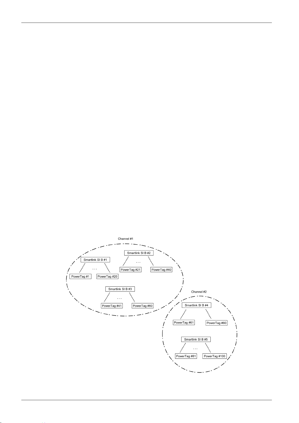
Principle of Wireless Device Installation
The Smartlink SI B gateway is installed in such a manner that the PowerTag energy sensors are
distributed around the concentrator. It is recommended to install the Smartlink SI B gateway in the center
of the switchboard for maximum data quality.
For example, when the switchboard is partitioned, and if you have three-column switchboard with
PowerTag energy sensors in each column, then install the Smartlink SI B gateway in the central cubicle.
For more than three columns of 650 mm in the same switchboard, add one Smartlink SI B gateway for
every three sections.
The system is compatible with Prisma Plus enclosure (form1 and form2), Prisma iPM form 1, Pragma, and
plastic final distribution enclosures. The distance between the concentrator and PowerTag energy sensors
should be smaller than 3 meters.
NOTE: For a good quality of radio frequency signal, it is recommended to install the PowerTag energy
sensors in the same switchboard.
DOCA0123EN-04 09/2020 23
Page 24
Architecture of Smartlink System
Maximum Number of PowerTag Energy Sensors in an Electrical Room
The wireless network configuration is used for special applications like data centers and high density
metering applications. In standard building applications, use the default settings.
At data centers, thousands of PowerTag energy sensors are placed in the same environment. Therefore,
it is necessary to consider the radio plan and bandwidth, in order to:
dispatch all the PowerTag energy sensors among the 16 available radio channels. It is recommended
to dispatch the Smartlink SI B gateways among the 16 channels using the manual channel selection in
this section.
use as many PowerTag energy sensors as possible in the same radio channel to increase the number
of points without decreasing the radio quality.
Following are the recommendations to slow down the communication period of the PowerTag energy
sensors that are in the same channel, to avoid overloading the bandwidth:
Up to 100 PowerTag energy sensors by radio channel: communication period to be set to 5 seconds
Up to 200 PowerTag energy sensors by radio channel: communication period to be set to 10 seconds
Up to 400 PowerTag energy sensors by radio channel: communication period to be set to 20 seconds
Up to 600 PowerTag energy sensors by radio channel: communication period to be set to 30 seconds
Up to 1200 PowerTag energy sensors by radio channel: communication period to be set to 60
seconds
Any modification to the communication period has to be done after the commissioning of the PowerTag
energy sensors is completed to avoid slowdown of the commissioning process.
NOTE: Modification in communication period does not slowdown the alarms. The voltage loss is sent
immediately on demand. The communication period is used to send regular metering data (P, U, I, E, PF),
not voltage loss alarms.
NOTE:
The radio channel is chosen in the wireless settings of Smartlink SI B gateway and is applied to all the
PowerTag energy sensors that are commissioned with Smartlink SI B gateway.
An Smartlink SI B gateway can manage up to 20 PowerTag energy sensors.
Several Smartlink SI B gateways can use the same radio channel to communicate with PowerTag
energy sensors.
A set of Smartlink SI B gateways has to be installed and commissioned to concentrate all the needed
PowerTag energy sensors.
24
DOCA0123EN-04 09/2020
Page 25

Devices out of the Acti9 Range
Description
The devices that can be connected to the Smartlink SI B gateway are:
Meter with a pulse output and compliant with standard IEC 62053-31.
Volt-Free Low Level Indication Contact.
Volt-Free Standard Indication Contact.
Contactor and Relay.
Indication device or PLC input can be directly connected to the output (Q) of Smartlink SI B gateway
channel.
The connected device should have the following characteristics:
To be powered with 24 Vdc.
The consumption must be less than 100 mA.
Any device (for example: motor) that needs a command circuit of more than 100 mA can be controlled
by the output (Q) of a channel of Smartlink SI B gateway. The electrical diagram must be indirect
between Smartlink SI B gateway and this device: a low level relay must be installed between the
command of this device and Smartlink SI B gateway.
NOTE: The connection of these devices can be done with an A9XCAU06 or A9XCAC01 pre-wired cable:
molded connector (at Smartlink end), and with five wires (at device end).
All sensors (compliant with IEC 61000-6-2 and IEC61000-6-3 standards) using one output (compatible with
4...20 mA or 0...10 V) can be directly connected to analog inputs of Smartlink SI B gateway (the cable for
analog channel is delivered with the product).
Architecture of Smartlink System
DOCA0123EN-04 09/2020 25
Page 26

Architecture of Smartlink System
Devices with Analog Output
Overview
All sensors (compliant with IEC 61000-6-2 and IEC61000-6-3 standards) using 24 Vdc as power supply
input and 0...10 V or 4...20 mA output can be connected to the Smartlink SI B gateway analog inputs
(female analog connector is delivered with the product).
26
DOCA0123EN-04 09/2020
Page 27

Smartlink SI B
Technical Characteris tics
DOCA0123EN-04 09/2020
Technical Characteristic s
Chapter 3
Technical Characteristics
What Is in This Chapter?
This chapter contains the following topics:
Technical Characteristics of the Smartlink SI B Gateway 28
Technical Characteristics of the Devices with Ti24 Interface 31
Topic Page
DOCA0123EN-04 09/2020 27
Page 28
Technical Characteristics
Technical Characteristics of the Smartlink SI B Gateway
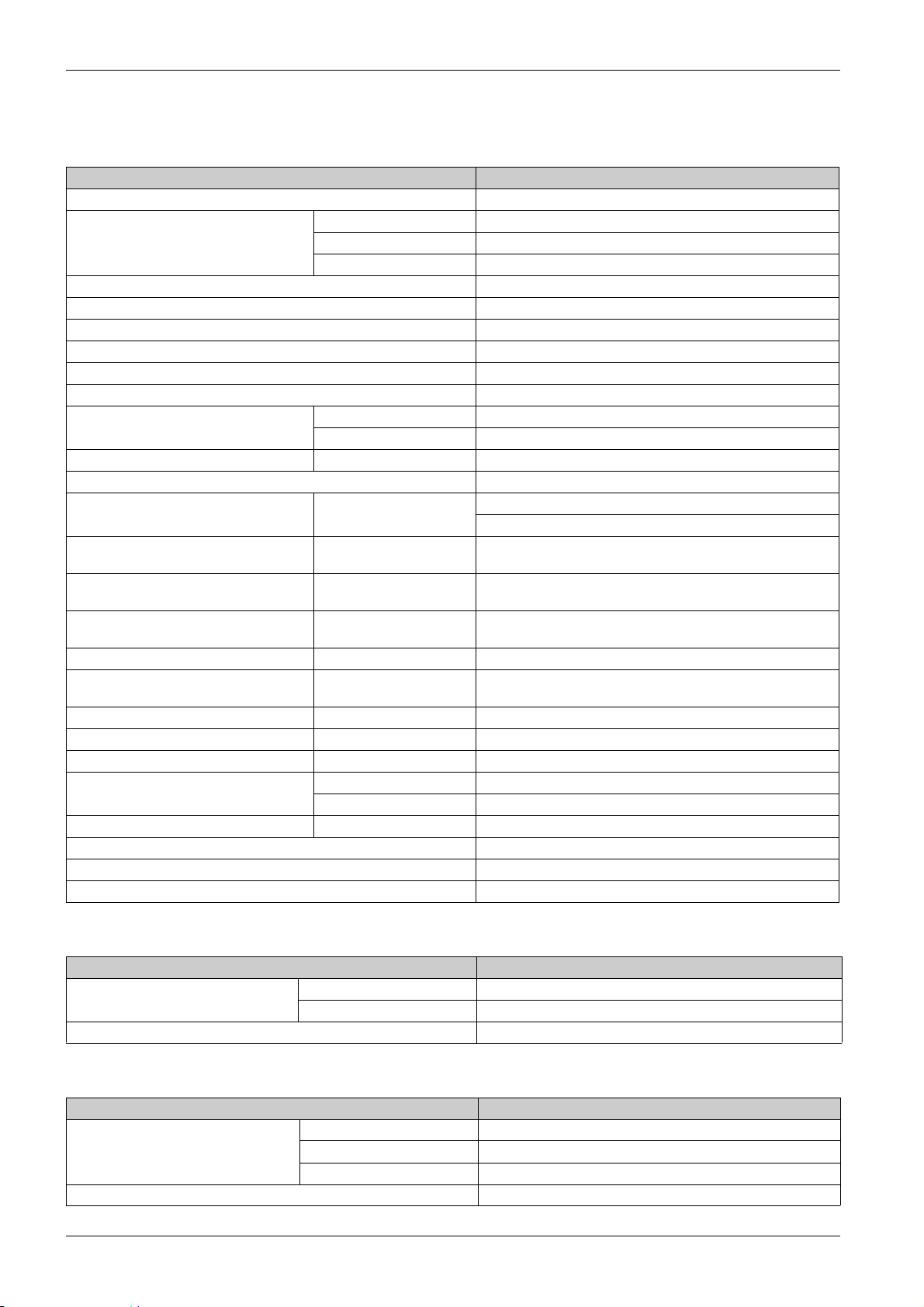
General Characteristics
Characteristic Value
Product marking CE
Temperature Operation (horizontal) –25...+60°C
Operation (vertical) –25...+50°C
Storage –40...+85°C
Tropicalization Execution 2 (relative humidity of 93% at 40°C)
Resistance to voltage dips 10 ms, class 3 according to IEC 61000-4-29
Degree of protection IP 20
Level of pollution 3
Overvoltage category OVC II
Conforming to SELV specifications Yes
Altitude Operation 0...2,000 m
Storage 0...3,000 m
Immunity to vibration IEC 60068-2-6 1 g/± 3.5 mm, 5...300 Hz, 10 cycles
Immunity to mechanical shock 15 g/11 ms
Immunity to electrostatic discharge IEC 61000-4-2 Air: 8 kV
Contact: 4 kV
Immunity to radiated electromagnetic
interference
Immunity to fast transients IEC 61000-4-4 1 kV for the I/O, Modbus and Ethernet communication.
Surge IEC 61000-4-5 Power supply: 0.5 kV
Immunity to conducted magnetic fields IEC 61000-4-6 10 V from 150 kHz to 80 MHz
Immunity to magnetic fields at line
frequency
Conducted emissions IEC 61131-2, CISPR Class A (0.15...30 MHz)
Radiated emissions IEC 61131-2, CISPR Class A (30...1000 MHz)
Resistance to corrosive atmospheres IEC 60721-3-3 Level 3C2 on H²S/SO²/NO²/Cl²
Fire withstand For live parts 30 s at 960°C. IEC 60695-2-10 and IEC 60695-2-11
Salt mist IEC 60068-2-52 Severity 2
Environment Conforms to RoHS directives
Installation position Horizontal or vertical
Mean time between failures More than 1 M hours
IEC 61000-4-3 10 V/m – 80 MHz to 3 GHz
2 kV for the 24 Vdc - 5 kHz - 100 kHz power supply
Modbus and Ethernet: 1 KV
IEC 61000-4-8 30 A/m continuous
100 A/m pulse
For other parts 30 s at 650°C. IEC 60695-2-10 and IEC 60695-2-11
Integrated Functions
Characteristic Value
Counter Number of counters Up to 14 (14 inputs)
Maximum frequency 16.667 Hz, IEC 62053-31
Period stored in backup memory 10 years
Mechanical Characteristics
Characteristic Value
Dimensions Length 359 mm
Height 22.5 mm
Depth 42 mm
Weight 180 g
28
DOCA0123EN-04 09/2020
Page 29
Technical Characteristics
Communication Module
Characteristic Value
Type of interface module Modbus RTU, RS485 serial connection
Modbus TCP/IP Ethernet
Transmission Modbus RS485 Transfer rate: 9,600...19,200 Baud
Medium: Double shielded twisted pair
Impedance 120 Ω
Ethernet Transfer rate: 10/100 Mbps
Structure Type Modbus, Ethernet
Method Master/Slave
Device type Modbus Master
Ethernet Server
Turnaround time Modbus 10 ms
Ethernet 1 ms
Maximum length of cable Modbus 1000 m
Ethernet 100 m
Type of bus connector Modbus 4-pin connector
Ethernet RJ45 (Shielded)
Power supply Nominal Non-isolated 24 Vdc with protection against negative voltages up to
Voltage limits 19.2... 28.8 Vdc with ripple
Current consumption, no-load 110 mA
Maximum input intensity 1.5 A
Maximum current inrush 3 A
Isolation Between the Modbus serial connection
and 24 Vdc Ti24 I/O interfaces
Between the Ethernet serial connection
and 24 Vdc Ti24 I/O interfaces
Number of digital I/O channels 7
Number of analog input channels 1
Number of Ethernet ports 1
Medium: Shielded, STP or S/FTP, Cat5e or 6, straight cable, RJ45
connector
-28.8 Vdc
1.9kVdc for 1minute
1.9kVdc for 1minute
Radio Frequency Characteristics
Characteristic Value
Radio communication ISM band 2.4...2.4835 GHz
Number of channels 11...26 (IEEE 802.15.4)
Equivalent isotropic radiated power (EIRP) 0 dBm
Number of radio frequency devices up to 20
RF standard compliance ETSI / EN 300328 v1.9.1
ETSI / EN 301489-17 v2.2.1
Digital Inputs
Characteristic Value
Number of logic inputs 14 (2 per channel)
Rated input voltage 24 Vdc
Input type Current sink, type 1
IEC 61131-2
Weight (0 V) 1 for 2 inputs (1 per channel)
Input voltage limits 19.2...28.8 Vdc
Rated input current 2.5 mA
DOCA0123EN-04 09/2020 29
Page 30
Technical Characteristics
Characteristic Value
Maximum input current 5 mA
Filter time 2 ms
Acquisition time 10 ms
Isolation No isolation between the Ti24 interfaces
Negative voltage protection Yes
Maximum length of cables and cordsets
500 m (conductor c.s.a. of at least 0.5 mm
Digital Outputs
Characteristic Value
Number of logic outputs 7 (1 per channel)
Logic output Current source, 24 Vdc 0.1 A
Weight (0 V) 1
Rated output voltage Voltage 24 Vdc
Maximum current 100 mA
Filter time 1 ms
Voltage drop (voltage at state 1) 1 V max.
Maximum current inrush 500 mA
Leakage current 0.1 mA
Overvoltage protection 33 Vdc
Short-circuit protection Yes
Overload protection Yes
Current limiting Yes
Maximum length of cables and cordsets
IEC 61131-2
500 m (conductor c.s.a. of at least 0.5 mm
2
)
2
)
Analog Inputs
Characteristic Value
Number of analog inputs 2
Type of each input Voltage/Current: IEC 61131 - 2 compliant
Rated input voltage 0...10 V
Rated input current 4...20 mA
Input impedance Current mode 140 Ω
Voltage mode 50 KΩ
Resolution 12 bits
Accuracy ≤ ± 1% of the full scale
Refresh time 500 ms
Isolation None
Type of cable Twisted shielded pair and screened cable
Cable length
Channel 8 (Analog inputs) maximum sourcing current at 24 V to power
< 30 m maximum
200 mA for each analog sensor
(1)
the sensors
Conversion time/Refresh time 100 ms
Connector type Screw type (4-pin), 3.5 mm pitch
(1)
NOTE:
Wrong wiring or wrong configuration can cause the analog input damage.
Introduce analog isolators (with 0.5 to 1% accuracy) when the cables go outside the switchboard where
Smartlink SI B gateway is mounted.
30
DOCA0123EN-04 09/2020
Page 31

Technical Characteristics
Technical Characteristics of the Devices with Ti24 Interface
iACT24
Characteristic Value
Control voltage (Ue) 230 Vac, +10 %, -15 % (Y2)
24 Vdc, ± 20 % (Y3)
Control voltage frequency 50/60 Hz
Insulation voltage (Ui) 250 Vac
Rated impulse withstand voltage (Uimp) 8 kV (OVC IV)
Level of pollution 3
Degree of protection IP20B device only
IP40 device in modular enclosure
Width in 9 mm modules 2
Auxiliary contact (O/C) Ti24 24 Vdc protected output, min. 2 mA, max. 100 mA
Contact 1 O/C operating category AC 14
Temperature Operation -25 … 60°C
Storage -40 … +80°C
Consumption < 1 W
Standard IEC/EN 60947-5-1
iATL24
Characteristic Value
Control voltage (Ue) 230 Vac, +10 %, -15 % (Y2)
24 Vdc, ± 20 % (Y3)
Control voltage frequency 50/60 Hz
Insulation voltage (Ui) 250 Vac
Rated impulse withstand voltage (Uimp) 8 kV (OVC IV)
Level of pollution 3
Degree of protection IP20B device only
IP40 device in modular enclosure
Width in 9 mm modules 2
Auxiliary contact (O/C) Ti24 24 Vdc protected output, min. 2 mA, max. 100 mA
Contact 1 O/C operating category AC 14
Temperature Operation -25 … 60°C
Storage -40 … +80°C
Consumption < 1 W
Standard IEC/EN 60947-5-1
OF+SD24 (A9N26899)
Characteristic Value
Insulation voltage (Ui) 500 Vac
Rated impulse withstand voltage (Uimp) 6 kV (OVC IV)
Rated operational current (le) 2...100 mA at 24 Vdc (± 20 %)
Level of pollution 2
Degree of protection IP20
Width in 9 mm modules 1
Temperature Operation -25 … 60°C
Storage -40 … +85°C
Standard IEC 60947-5-1
IEC 60947-5-4
DOCA0123EN-04 09/2020 31
Page 32

Technical Characteristics
iOF+SD24 (A9A26897)
Characteristic Value
Insulation voltage (Ui) 500 Vac
Rated impulse withstand voltage (Uimp) 6 kV (OVC IV)
Rated operational current (le) 2...100 mA at 24 Vdc (± 20 %)
Level of pollution 2
Degree of protection IP20B device only
Width in 9 mm modules 1
Temperature Operation -35 …70°C
Storage -40 … +85°C
Standard IEC 60947-5-1
IP40 device in modular enclosure
IEC 60947-5-4
iOF/SD24 (A9A19804)
Characteristic Value
Insulation voltage (Ui) 500 Vac
Rated impulse withstand voltage (Uimp) 6 kV (OVC IV)
Rated operational current (le) 2...100 mA at 24 Vdc (± 20 %)
Level of pollution 2
Degree of protection IP20B
Width in 9 mm modules 1
Temperature Operation -25 …60°C
Storage -40 … +85°C
Standard IEC 60947-5-1
IEC 60947-5-4
32
DOCA0123EN-04 09/2020
Page 33

Smartlink SI B
Sizing the 24 Vdc Power Supply
DOCA0123EN-04 09/2020
Sizing the 24 Vdc Power Supply
Chapter 4
Sizing the 24 Vdc Power Supply
What Is in This Chapter?
This chapter contains the following topics:
Definition of the 24 Vdc Power Supply 34
Protection Against a 240 Vac Fault on the Smartlink SI B Gateway Channels 36
Electromagnetic Compatibility (EMC) Recommendations 37
Topic Page
DOCA0123EN-04 09/2020 33
Page 34

Sizing the 24 Vdc Power Supply
Definition of the 24 Vdc Power Supply
Safety Information
RISK OF ELECTROCUTION
Isolate the 24 V power terminals of the Smartlink SI B gateway from the power terminals connected to
the Modbus network line.
Failure to follow these instructions will result in death or serious injury.
Example: The 0 V and the 24 V of a 24 Vdc power supply connected to the TRV00210 ULP communication
module must be isolated from the 0V or +24 V terminals of the 24 Vdc power supply for the Smartlink SI B
gateway.
General Characteristics
The Smartlink SI B gateway consumption:
Status Consumption
Device with no load 110 mA
Device under load 1.5 A maximum
DANGER
Products in the Acti9 Range
If products connected to the channels (Ti24 interfaces) of a Smartlink SI B gateway are in the Acti9 range,
the consumption of a channel output is the same as the consumption of an input because the output is
connected to the input. All that needs to be done is to add up the consumption of three input currents per
channel.
Example: Assuming that the input current is less than 5 mA and two analog sensors are connected to
Smartlink SI B gateway, the consumption of a Smartlink Ethernet Wireless device is as follows:
No-load consumption + (number of digital channels x 3 input currents) + (Analog sensor x 2) = 110 mA +
(7 x (3 x 5 mA)) + (200 mA x 2) = 615 mA
Products that can be Controlled by a Channel
If products connected to the channels (Ti24 interfaces) of a Smartlink SI B gateway are in a different range,
the maximum consumption of a device channel is 110 mA. The output for each channel supplies 100 mA,
the digital inputs can consume up to 10 mA and the analog input can consume up to 200 mA.
Example: Assuming that the consumption of one channel is 110 mA, the consumption of one
Smartlink SI B gateway is as follows:
No-load consumption + (number of digital channels x consumption per channel) + (Analog sensor x 2)
= 110 mA + (7 x 110 mA) + (200 mA x 2) = 1.3 A
Selection of the Smartlink SI B Gateway 24 Vdc Power Supply
The 24 Vdc power supply must correspond to the following criteria:
It must be located inside the electrical cabinet.
It must be different from the Modbus network 24 Vdc power supply so as to maintain galvanic isolation
between the Modbus network (common to several electrical cabinets) and the 24 Vdc I/O.
It must be Safety Extra Low Voltage (SELV) type.
Galvanic isolation between the power supply input (AC voltage) and the power supply output (DC
voltage) must be at least 3 kVac at 50 Hz.
The rated AC voltage of the power supply input must be 240 Vac +15/–20%.
This power supply can be used to supply other products inside the electrical cabinet provided that these
products are double insulated or with reinforced insulation so as to preserve the power supply's SELV
quality.
Phaseo ABL8MEM240xx (OVC II) or ABL7RM24025 (OVC II) modular power supplies and their
accessories comply with the above recommendations. These accessories provide the redundancy and
backup power supply functions and can eliminate micro-cuts on the line.
34
DOCA0123EN-04 09/2020
Page 35

The upstream and downstream protection functions of the Phaseo power supply must be installed as
indicated in their respective manuals.
NOTE: OVC indicates the overvoltage category.
If overvoltage category IV or III is needed in the installation, we recommend using:
Either power supplies (limited to 1 A) in the ULP (Universal Logic Plug) system with product references
54440 to 54445. See the User’s Manual, ULP Connection System, product reference TRV99100
Or use the Phaseo power supply recommended above, protecting it with an isolating transformer from
the Phaseo Optimum (ABL6TS) range or the Universal (ABT7PDU) range.
NOTE: For each of these solutions, you should refer to the respective manuals.
Protection Against a 240 Vac Fault on the Smartlink SI B Gateway 24 Vdc Input
A fuse protection is provided if a 240 Vac power supply is accidentally connected to the 24 Vdc input on
the Smartlink SI B gateway power supply.
Sizing the 24 Vdc Power Supply
DOCA0123EN-04 09/2020 35
Page 36

Sizing the 24 Vdc Power Supply
Protection Against a 240 Vac Fault on the Smartlink SI B Gateway Channels
Overview
In the event of a wiring error or electrical fault, the 240 Vac voltage may be present on the
Smartlink SI B gateway channels: the neutral or phase (240 Vac) can be in contact with the Ti24 interfaces
or the 24 Vdc power supply.
The insulation inside the Smartlink SI B gateway prevents propagation of this dangerous voltage (240 Vac)
over the Modbus and Ethernet network.
The protection function inside the Smartlink SI B gateway eliminates the risk of fire inside the
Smartlink SI B gateway.
These two protection functions (internal insulation and internal protection) cannot prevent wiring errors or
electrical faults. A risk of dangerous voltage remains on the Smartlink SI B gateway channels.
DANGER
HAZARD OF ELECTRIC SHOCK, EXPLOSION, OR ARC FLASH
Implement a TT or TN-S earthing system.
Connect the SELV (Safety Extra Low Voltage) power supply 0 Vdc to the protective earth to make it a
PELV (Protective Extra Low Voltage) power supply. The upstream residual current protection must be
type A.
Failure to follow these instructions will result in death or serious injury.
NOTE: In the majority of cases, the presence of a PELV means an upstream residual current protection
can trip, thus protecting people and property.
DANGER
ACCIDENTAL EQUIPMENT BEHAVIOR
Connect the 0 Vdc of the SELV power supply to the protective earth at a single point to avoid any stray
currents (50 Hz, harmonics, or transient currents) circulating across the 0 Vdc.
Check that products supplied by this power supply are not already connecting the 0 Vdc to the
protective earth.
Failure to follow these instructions will result in death or serious injury.
NOTICE
RISK OF DAMAGING THE SMARTLINK DEVICE
Connect the 0 Vdc of the SELV power supply to the protective earth at a single point to avoid any stray
currents (50 Hz, harmonics, or transient currents) circulating across the 0 Vdc.
Check that products supplied by this power supply are not already connecting the 0 Vdc to the
protective earth.
Failure to follow these instructions can result in equipment damage.
36
DOCA0123EN-04 09/2020
Page 37

Electromagnetic Compatibility (EMC) Recommendations
Overview
A star 24 Vdc distribution is preferable to a serial 24 Vdc distribution because star 24 Vdc distribution can
minimize the wiring impedance.
If serial distribution is used, it is recommended to wire two serial loopback wires (see the two blue wires in
the drawing below) in order to minimize impedance.
In a poor-quality electrical distribution network, it is recommended to use a Phaseo power supply from the
Universal range (ABL8MEM240xx (OVC II) or ABL7RM24025 (OVC II)) which can withstand up to 500 Vac
incoming and also offers galvanic insulation between the power supply AC input and the power supply DC
output of 4 kVac at 50 Hz.
It is mandatory to comply with the segregation rules between low level signals (24 Vdc) and power
conductors, see:
www.electrical-installation.org
"Wiring recommendations" section (information only available in English).
Electrical Installation Guide in pdf format: Document No. EIGED306001EN.
see "ElectroMagnetic Compatibility (EMC)" part,
Sizing the 24 Vdc Power Supply
DOCA0123EN-04 09/2020 37
Page 38

Sizing the 24 Vdc Power Supply
38
DOCA0123EN-04 09/2020
Page 39

Smartlink SI B
Installation
DOCA0123EN-04 09/2020
Installation
Chapter 5
Installation
What Is in This Chapter?
This chapter contains the following topics:
Mounting 40
Connection 46
Topic Page
DOCA0123EN-04 09/2020 39
Page 40

Installation
Mounting
Introduction
The Smartlink SI B gateway can be mounted on:
DIN rail
Multiclip 80
Multiclip 200
Mounting brackets
Mounting Kit for Pragma and Kaedra
The Smartlink SI B gateway can be installed horizontally or vertically:
In a horizontal mounting, Smartlink SI B gateway is clipped onto DIN rails with fixing centers of 150 mm
or more.
Wall-mounted and floor-standing enclosures must be at least 24 modules wide (18 mm x 24 = 432 mm).
The distance between the DIN rail and the back of the wall-mounted or floor-standing enclosure must
be at least 50 mm.
40
The ambient operating temperature is:
Horizontal mounting: −25°...+60°C
Vertical mounting: −25°...+50°C
DOCA0123EN-04 09/2020
Page 41

Mounting Components
DIN Rail Mounting
The side of the foot (A or B in the drawing below) used to mount the system on the DIN rail depends on
the type of rail (aluminum or iron).
Installation
Product Reference Description
A9XMZA08 Smartlink SI B gateway
A9XMFA04 Set of bracelets, adapters, and feet for DIN rail mounting
A9XM2B04 Spacers for Multiclip 200 mounting
A9XMBP02 Mounting brackets kit
The following table describes the procedure for mounting the Smartlink SI B gateway on a DIN rail:
Step Action
1 Clip one bracelet onto one foot according to the type of rail. Repeat this step three times.
2 Clip the Smartlink SI B gateway on top of the bracelets.
3 Place the top of the foot at an angle against the top lip of the rail.
4 Clip the bottom of the foot into place.
5 Repeat steps 3 and 4 for each of the other three feet.
DOCA0123EN-04 09/2020 41
Page 42

Installation
Simple DIN Rail Mounting
To mount the system on a simple DIN rail (iron), use side A of the foot.
The following table describes the procedure for mounting the Smartlink SI B gateway on a simple DIN rail:
Step Action
1 Clip one bracelet onto side A of a foot. Repeat this step three times.
2 Place one M6 nut inside a foot. Repeat this step three times.
3 Position the top of an adapter diagonally at the front of a foot.
4 Clip the bottom of the adapter into place. Repeat steps 3 and 4 three times.
5 Drill the rail making sure that the drill hole diameters and positioning dimensions are correct, as shown in the above graphic.
6 Screw the feet onto the rail.
Mounting on Multiclip 80
The following table describes the procedure for mounting the Smartlink SI B gateway on Multiclip 80.
Step Action
1 Position the two clips in the notches on the Smartlink SI B gateway.
2 Slide the Smartlink SI B gateway front first onto the Multiclip 80 until fully inserted.
3 Push down the two clips until they click into place.
42
DOCA0123EN-04 09/2020
Page 43

Mounting on Multiclip 200
The following table describes the procedure for mounting the Smartlink SI B gateway on Multiclip 200.
Step Action
1 Slide the four spacers from the back into the notches on top of the Multiclip 200.
2 Slide the Smartlink SI B gateway front first onto the spacers, until it clicks into place.
Mounting with Brackets
Installation
The following table describes the procedure for mounting the Smartlink SI B gateway with brackets.
Step Action
1 Drill the plate of the cubicle making sure that the drill hole diameters and positioning dimensions are correct, as shown in the
preceding graphic.
2 Slide the 2 brackets, from the back of the Smartlink SI B gateway, into the notches on the bottom of the Smartlink SI B gateway
until they click into place.
3 Screw the brackets onto the plate.
DOCA0123EN-04 09/2020 43
Page 44

Installation
Mounting Kit for Pragma and Kaedra
Mounting Possibilities for Kaedra Surface Panel
Smartlink SI B Gateway (A9XMEA08, A9XMZA08) and A9XMVA01 Surface Enclosures
Smartlink: Mounted Vertical Kaedra 13M 3R
Kaedra 18M 3R
Smartlink: Mounted Horizontal Kaedra 18M 1R
Kaedra 18M 2R
Kaedra 18M 3R
Kaedra 18M 4R
44
DOCA0123EN-04 09/2020
Page 45

Mounting Possibilities for Pragma Surface Panel
Installation
Smartlink SI B Gateway (A9XMEA08, A9XMZA08) and A9XMVA01 Surface Enclosures
Smartlink: Mounted Vertical Pragma 13M 3R
Smartlink : Mounted Horizontal Pragma 18M 1R
Pragma 13M 4R
Pragma 18M 3R
Pragma 18M 4R
Pragma 18M 2R
Pragma 18M 3R
Pragma 18M 4R
Pragma 24M 1R
Pragma 24M 2R
This kit allows you to install Smartlink SI B gateway inside some of the Pragma and Kaedra panels.
Step Action
1 Screw the A9XMVA01 kit either horizontally or vertically on the Pragma and Kaedra panel.
2 Slide and clip the Smartlink SI B gateway on the mounting kit.
DOCA0123EN-04 09/2020 45
Page 46

Installation
Connection
Safety Instructions
DANGER
RISK OF ELECTRIC SHOCK, EXPLOSION, OR ARC FLASH
Wear suitable personal protective equipment and follow the currently applicable electrical safety
instructions.
This equipment may only be installed by qualified electricians who have read all the relevant
information.
NEVER work alone.
Before performing visual inspections, tests, or maintenance on this equipment, disconnect all sources
of electric power. Assume that all circuits are live until they have been completely de-energized, tested
and tagged. Pay particular attention to the design of the power system. Consider all power supply
sources, particularly the potential for backfeed.
Before closing protective covers and doors, carefully inspect the work area to ensure that no tools or
objects have been left inside the equipment.
Take care when removing or replacing panels. Take special care to ensure that they do not come into
contact with live busbars. To minimize the risk of injuries, do not tamper with the panels.
The successful operation of this equipment depends upon proper handling, installation, and operation.
Failure to follow basic installation procedures can lead to personal injury as well as damage to
electrical equipment or other property.
NEVER shunt an external fuse/circuit breaker.
This equipment must be installed inside a suitable electrical cabinet.
Failure to follow these instructions will result in death or serious injury.
RISK OF ELECTROCUTION
Isolate the power terminals of the Smartlink SI B gateway from the power terminals connected to the
Modbus network line.
Failure to follow these instructions will result in death or serious injury.
Connecting the Power Supply Connector
DANGER
The following table describes the procedure for connecting the power supply connector:
Step Action
1 Insert both stripped power supply wires in the connector.
2 Fix the wires in place using the connector tightening screws.
46
DOCA0123EN-04 09/2020
Page 47

The following figure gives the characteristics of cables that can be used to connect the 24 Vdc power
supply:
Connecting the Modbus Connector
The Schneider Electric communication cables to be used are:
Product Reference Description Length (m)
50965 RS 485 double shielded twisted pair cable for Modbus serial link (supplied without connector) 60
Installation
NOTE:
It is possible to use a common 24 Vdc power-supply for several Smartlink SI B gateways if installed in
the same switchboard.
DOCA0123EN-04 09/2020 47
Page 48

Installation
NOTICE
HAZARD OF NON-OPERATION OF MODBUS NETWORK
Comply with the wiring and connection rules described below in order to create a working Modbus
network.
Failure to follow these instructions can result in equipment damage.
The following table describes the procedure for connecting the Modbus connector:
Step Action
1 Coil up the Modbus communication cable shielding.
2 Cut the shielding 20 mm from the sheath.
3 Insert the stripped wires in the connector terminals as shown in the above graphic.
4 Fix the wires in place using the connector tightening screw.
The following figure gives the characteristics of cables that can be used to connect the Modbus connector:
Checking the Modbus Serial Link
The following table gives the characteristics of the RS 485 link that need to be checked during installation:
Designation Description
Shielding connection Each Modbus serial link must have shielding connected at one point to an earthed link.
Bus polarization
Pull-up resistor connected to the 5 V: 450...650 Ohm
Pull-down resistor connected to ground (Modbus 0 V): 450...650 Ohm
NOTE: This polarization is recommended for the master.
Line terminator A 150 Ohm resistor ± 5%
Ground polarity The ground circuit (0 V of an optional power supply) must be connected directly to a protected earth,
preferably at a single point on the bus.
This point is usually placed on the master or its slaves.
Trunk cable A pair of shielded twisted cables and a third conductor at minimum.
Maximum length of bus 1000 m at 19,200 Baud with the Schneider Electric 50965 cable.
48
DOCA0123EN-04 09/2020
Page 49

Smartlink SI B
Connection of Input/Output Channels
DOCA0123EN-04 09/2020
Connection of Input/Outp ut Channels
Chapter 6
Connection of Input/Output Channels
What Is in This Chapter?
This chapter contains the following topics:
Acti9 Devices with Ti24 Interface 50
Meters 51
Volt-Free Low Level Indication Contact 52
Volt-Free Standard Indication Contact 53
Surge Arresters 54
Contactor and Relay (Not in the Acti9 Range) 57
Direct Output Connection 58
Indirect Output Connection 59
Generating Summary Data Using iOF+SD24, OF+SD24, OF24, or SD24 60
Analog Input Characteristics and Connection (Recommendation) 62
Recommendation for Cabling 63
Topic Page
DOCA0123EN-04 09/2020 49
Page 50

Connection of Input/Output Channels
Acti9 Devices with Ti24 Interface
Overview
Auxiliary devices such as iACT24, iATL24, OF+SD24, OF/SD24, RCA iC60, and Reflex iC60 can be
connected to the Smartlink SI B gateway with the Smartlink system pre-asssembled cables.
Wiring
The figure below shows the connection of auxiliary devices to the Smartlink SI B gateway with the
Smartlink system pre-assembled cables:
NOTE: A9XCAU06 or A9XCAC01 cable could be used to link Acti9 devices with Ti24 interface to
Smartlink SI B gateway.
In this case, for the connection of iACT24 and iATL24, input I2 must be connected on both ends of
A9XCAU06 or A9XCAC01 cable.
50
DOCA0123EN-04 09/2020
Page 51

Meters
Overview
Wiring
Connection of Input/Output Channels
The PM3210, iEM2000T, iEM3110, iEM3155, iEM3210, iEM3255, and iEM3355 products are kilowatt-hour
pulse meters from the Schneider Electric range.
Meters not in the Acti9 range can be controlled by a Smartlink SI B gateway channel. These meters must
have the following characteristics:
1 pulse output
Compatibility with IEC 62053-31 standard
The PM3210, iEM2000T, iEM3110, iEM3155, iEM3210, iEM3255, and iEM3355 kilowatt-hour pulse
meters can be connected to channel N (1 ≤ N ≤ 7) of a Smartlink SI B gateway with an A9XCAU06 or
A9XCAC01 pre-wired cable: molded connector (at Smartlink SI B gateway end), and with 5 wires (at
iEM2000T end).
NOTE: A single Smartlink SI B gateway channel can take account of 2 meters, 1 meter on input I1, and
1 meter on input I2.
NOTE:
Do not connect 2 wires in each of the Ti24 connector terminals (A9XC2412).
Do not connect a wire with cable end in each of the Ti24 connector terminals.
Example of Connection of iEM2000T Pulse Meters
1 iEM2000T meter
2 iEM2000T meter
DOCA0123EN-04 09/2020 51
Page 52

Connection of Input/Output Channels
Volt-Free Low Level Indication Contact
Overview
A low level type indication contact (NO or NC) can be connected to input I1 or I2 of a Smartlink SI B
gateway channel.
NOTE: A single Smartlink SI B gateway channel can take account of two indication contacts, one contact
on input I1, and one contact on input I2.
Wiring
An indication contact can be connected with an A9XCAU06 or A9XCAC01 pre-wired cable: molded
connector (at Smartlink SI B gateway end, and with the five wires (indication contact end)).
NOTE:
Do not connect 2 wires in each of the Ti24 connector terminals (A9XC2412).
Do not connect a wire with cable end in each of the Ti24 connector terminals.
Example of Connection
The OF and SD contacts of a NSX circuit breaker could be directly connected to a Smartlink SI B gateway.
52
DOCA0123EN-04 09/2020
Page 53

Volt-Free Standard Indication Contact
Overview
A standard indication contact (NO or NC) can be connected to input I1 or I2 of a Smartlink SI B gateway
channel.
NOTE: A single Smartlink SI B channel can take account of two indication contacts, one contact on input
I1 and one contact on input I2. The electrical diagram must be indirect between Smartlink SI B gateway
and this device: a low level relay must be installed between the contact of this device and Smartlink SI B
gateway.
Wiring
An indication contact can be connected with an A9XCAU06 or A9XCAC01 pre-wired cable: molded
connector (at Smartlink SI B gateway end, and with the five wires (indication contact end).
Connection of Input/Output Channels
NOTE:
Do not connect two wires in each of the Ti24 connector terminals (A9XC2412).
Do not connect a wire with cable end in each of the Ti24 connector terminals.
Example of Connection
(1) NG125 circuit breaker: OF+SD auxiliary contacts with a minimum current of 100 mA
(2) iRBN relay for OF signal
(3) iRBN relay for SD signal
DOCA0123EN-04 09/2020 53
Page 54

Connection of Input/Output Channels
Surge Arresters
Overview
Acti9 surge arresters can be connected to Smartlink SI B gateway:
The remote transfer contact (indication contact: NO) of an Acti9 surge arrester can be connected to
input I1 or I2 of a Smartlink SI B gateway channel.
The SD fault-trip indication contact (indication contact: NC) of the circuit breaker associated to an Acti9
surge arrester can be connected to input I1 or I2 of an Smartlink SI B gateway channel.
NOTE: A single Smartlink SI B gateway channel can take account of two indication contacts, one contact
on input I1 and one contact on input I2.
Wiring
An indication contact can be connected with an A9XCAU06 or A9XCAC01 pre-wired cable: molded
connector (at Smartlink SI B gateway end), and with the five wires (indication contact end).
The following wiring is dedicated to surge arresters:
iPRD
iPRD 40r PV
iQuick PRD
The following wiring is dedicated to surge arresters:
iPRF1 12.5r
PRD1 25r
PRD1 Master
NOTE:
Do not connect 2 wires in each of the Ti24 connector terminals (A9XC2412).
Do not connect a wire with cable end in each of the Ti24 connector terminals.
54
DOCA0123EN-04 09/2020
Page 55

Examples of Connection
The following electrical diagram is dedicated to iPRD surge arrester.
(1) Remote transfer contact of iPRD surge arrester: cartridges status
(2) iSD fault-trip indication contact of iC60 circuit breaker associated to iPRD surge arrester
The following electrical diagram is dedicated to surge arresters:
iPRD 40r PV
iQuick PRD
Connection of Input/Output Channels
(1) Remote transfer contact of surge arrester: cartridges status
The following electrical diagram is dedicated to iPRF1 12.5r surge arresters:
(1) Remote transfer contact of iPRF1 12.5r surge arrester: surge arrester status
(2) iSD fault-trip indication contact of NSX160F or NG125 circuit breaker associated to iPRF1 12.5r surge arrester
DOCA0123EN-04 09/2020 55
Page 56

Connection of Input/Output Channels
The following electrical diagram is dedicated to surge arresters:
PRD1 25r
PRD1 Master
(1) Remote transfer contact of PRD1 25r or PRD1 Master surge arrester: cartridges status
(2) iSD fault-trip indication contact of NSX160 circuit breaker associated to PRD1 25r or PRD1 Master surge arrester
56
DOCA0123EN-04 09/2020
Page 57

Contactor and Relay (Not in the Acti9 Range)
Overview
A contactor or relay powered with 24 Vdc can be connected to Smartlink SI B gateway. This should have
the following characteristics:
The contactor or relay coil must not draw more than 100 mA.
The indication contact must be low level type.
Only contactors in the Acti9 range can be connected to Smartlink SI B gateway using the iACT24 auxiliary.
Wiring
A contactor can be connected with an A9XCAU06 or A9XCAC01 pre-wired cable: molded connector (at
Smartlink SI B gateway end), and with five wires (at contactor end).
NOTE:
Do not connect 2 wires in each of the Ti24 connector terminals (A9XC2412).
Do not connect a wire with cable end in each of the Ti24 connector terminals.
Connection of Input/Output Channels
Example of Connection
1 Low level relay (for example, iRBN)
2 24 Vdc relay
3 Power contactor (for example, TeSys D, type LC1)
DOCA0123EN-04 09/2020 57
Page 58

Connection of Input/Output Channels
Direct Output Connection
Overview
An indication device or a PLC input can be directly connected to the output (Q) of Smartlink SI B gateway
channel.
The connected device should have the following characteristics:
To be powered with 24 Vdc.
The consumption must be less than 100 mA.
Wiring
The wiring can be done with an A9XCAU06 or A9XCAC01 pre-wired cable: molded connector (at
Smartlink SI B gateway end), and with five wires (at contactor end).
NOTE:
Do not connect two wires in each of the Ti24 connector terminals (A9XC2412).
Do not connect a wire with cable end in each of the Ti24 connector terminals.
Example of Connection
(1) Indication light 24 Vdc
58
DOCA0123EN-04 09/2020
Page 59

Indirect Output Connection
Overview
Any device (for example: motor) that needs a command circuit of more than 100 mA can be controlled by
the output (Q) of a Smartlink SI B gateway channel. The electrical connection between Smartlink SI B
gateway and the device must be indirect. A low level relay must be installed between the command of the
connected device and the Smartlink SI B gateway.
Wiring
The wiring can be done with an A9XCAU06 or A9XCAC01 pre-wired cable: molded connector (at
Smartlink SI B gateway end), and with five wires (at contactor end).
NOTE:
Do not connect two wires in each of the Ti24 connector terminals (A9XC2412).
Do not connect a wire with cable end in each of the Ti24 connector terminals.
Connection of Input/Output Channels
Example of Connection
(1) Relay iRTBT
(2) Contactor Tesys D LC1D•25 with an 230 Vac coil
(3) Motor 10 kW with power supply 3-phases 380 Vac
DOCA0123EN-04 09/2020 59
Page 60

Connection of Input/Output Channels
Generating Summary Data Using iOF+SD24, OF+SD24, OF24, or SD24
Overview
The electrical summary of the SD contacts or summary of the OF contacts can be generated with
iOF+SD24, OF+SD24, OF24, and/or SD24 auxiliaries.
The electrical summary of the OF signals can be done by cabling in series of all OF signals and by
connecting this circuit to the I1 input of a Smartlink SI B gateway channel.
The electrical summary of the SD signals can be done by cabling in series of all SD signals and by
connecting this circuit to the I2 input of another Smartlink SI B gateway channel.
The OF connections (on I1 input) and the SD connections (on I2 input) cannot be connected to the same
Smartlink SI B gateway channel, as the summary information dedicated to the OF signals cannot be
separated from the summary information dedicated to the SD signals in Smartlink SI B gateway.
The two new auxiliaries are OF24 and SD24, where OF24 has a breaker with Open/Close status and SD24
has a breaker with Tripped status.
The summary of OF (or SD) signals can be wired in series using the A9XC2412 15-pin connector (spring
cage). A maximum of 10 OF (or SD) signals can be wired in the same summary.
NOTE: For a new configuration iOF+SD24 does not exist anymore but OF+SD24 auxiliary is used instead.
Wiring SD Contacts on iOF+SD24 or OF+SD24 in Series
60
(1) Input I2 (of a channel) on Smartlink SI B gateway or PLC input
DOCA0123EN-04 09/2020
Page 61

Wiring OF Contacts on iOF+SD24 or OF+SD24 in Series
Connection of Input/Output Channels
(1) Input I1 (of a channel) on Smartlink SI B gateway or PLC input
DOCA0123EN-04 09/2020 61
Page 62

Connection of Input/Output Channels
Analog Input Characteristics and Connection (Recommendation)
Overview
Analog Input Characteristics Value
Number of analog inputs 2
Type of input Voltage/Current: IEC 61131 - 2
Rated input voltage 0...10 V
Rated input current 4...20 mA
Input impedance for current mode 140 Ω
Input impedance for voltage mode 50 kΩ
Resolution 12 bits
Accuracy ≤ ±1% of the full scale
Refresh time 500 ms
Isolation None
Type of cable Twisted shielded pair or screened cable
Cable length
Channel 8 (analog inputs) maximum sourcing current at 24 V to power
the sensors
Conversion time/Refresh time 100 ms
Connector type Screw type (4-pin), 3.5 mm pitch
< 30 m maximum
200 mA for each analog sensor
(1)
NOTE:
(1)
The instruction for missed wiring or wrong configuration can result in input damage.
62
DOCA0123EN-04 09/2020
Page 63

Connection of Input/Output Channels
Recommendation for Cabling
Connecting the Analog Input Connector
The following table gives the details of the cable reference and specifications of the analog input connector:
Cable Reference Specifications Cable Stripping Length
Manufacturer Alpha wire STP Cable (shielded twisted pair
Part reference 3303 Cable length < 30 m 7 mm
– AWG between 26 - 16 –
Wiring
NOTICE
RISK OF DAMAGING THE EQUIPMENT
Ensure that the analog channel configuration and physical connection is accurate.
Failure to follow these instructions can result in equipment damage.
The reference of the analog input connector are:
Manufacturer: Phoenix
Commercial reference: 1916410
Description: PTB PLUG 3.5 NA FMLE MCSCW 4 1x4 PA
The following figure shows the sensor powered by Smartlink SI B gateway:
1 Consumption or each AI1 or AI2: 200 mA
2 The shield must be connected to ground near the Smartlink SI B gateway with a clamp only
3 Twisted pair, shielded cable
4 Sensor (current/voltage) compliant with IEC 61000-6-2 and IEC61000-6-3 standards
DOCA0123EN-04 09/2020 63
Page 64

Connection of Input/Output Channels
The following figure shows the sensor powered by external power supply:
1 Consumption or each AI1 or AI2: 200 mA
2 The shield must be connected to ground near the Smartlink SI B gateway with a clamp only
3 Twisted pair, shielded cable
4 Sensor (current/voltage) compliant with IEC 61000-6-2 and IEC61000-6-3 standards
5 External power supply
If the analog sensor is placed outside the panel, then an analog isolator is recommended as per the system
specifications.
1 Smartlink SI B gateway
2 Analog isolator
3 Sensor (current/voltage) compliant with IEC 61000-6-2 and IEC61000-6-3 standards
Connecting the Ethernet Connection
The connection between Smartlink SI B gateway and other Ethernet devices is done using a standard
straight Ethernet cable (shielded, STP or S/FTP, Cat5e or 6, RJ45 connector).
If Smartlink SI B gateway is mounted on Multiclip 200, the cable must be a right angle RJ45 Ethernet cable
in order to install a cover in the panel.
64
DOCA0123EN-04 09/2020
Page 65

Connection of Input/Output Channels
RJ45 Connector and Signal Pin
The following table gives the details of RJ45 connector and signal description:
RJ45 Female Pin Number Signal RJ45 Male Plug Pair Signal Description
1 TX+ A Transmit+
2 TX- A Transmit-
3 RX+ B Receive+
4 Not connected – Not connected
5 Not connected – Not connected
6 RX- B Receive-
7 Not connected – Not connected
8 Not connected – Not connected
DOCA0123EN-04 09/2020 65
Page 66

Connection of Input/Output Channels
66
DOCA0123EN-04 09/2020
Page 67

Smartlink SI B
Getting Started with Sm artlink SI B Gat eway
DOCA0123EN-04 09/2020
Getting Started with SmartlinkSI B Gateway
Chapter 7
Getting Started with Smartlink SI B Gateway
What Is in This Chapter?
This chapter contains the following sections:
Section Topic Page
7.1 General Principle to Commission a Smartlink SI B Gateway System 68
7.2 Commissioning a Smartlink SI B Gateway System with EcoStruxure Power
69
Commission Software
7.3 Commissioning a Smartlink SI B Gateway with Webpages 73
DOCA0123EN-04 09/2020 67
Page 68

Getting Started with Smartlink SI B Gateway
General Principle to Co mmission a Smart link SI B Gateway System
Section 7.1
General Principle to Commission a Smartlink SI B Gateway System
Commissioning Overview
Overview
The commissioning of an Smartlink SI B gateway system can be performed using:
the EcoStruxure Power Commission software, refer to
the Smartlink SI B webpages. The webpages are autonomous to configure any devices connected or
paired with Smartlink SI B gateway.
However, if the Smartlink SI B gateway system is composed of many devices, it is easier to commission
the devices with EcoStruxure Power Commission software.
NOTE:
Before commissioning the Smartlink SI B gateway, update the firmware of the Smartlink SI B gateway.
The firmware upgrade of the Smartlink SI B gateway can only be done using the EcoStruxure Power
Commission software, refer to
EcoStruxure Power Commission Online Help
EcoStruxure Power Commission Online Help
.
68
DOCA0123EN-04 09/2020
Page 69

Commissioning a Smartlink SI B Gateway System with EcoStruxure Power Commission Software
Section 7.2
Commissioning a Smartlink SI B Gateway System with EcoStruxure
Power Commission Software
What Is in This Section?
This section contains the following topics:
Installation of EcoStruxure Power Commission Software 70
Commissioning with EcoStruxure Power Commission Software 71
Getting Started with Smartlink SI B Gateway
Topic Page
DOCA0123EN-04 09/2020 69
Page 70

Getting Started with Smartlink SI B Gateway
Installation of EcoStruxure Power Commission Software
Downloading and Installation
To download and install the EcoStruxure Power Commission software, refer
Commission Installation Guide
.
EcoStruxure Power
70
DOCA0123EN-04 09/2020
Page 71

Getting Started with Smartlink SI B Gateway
Commissioning with EcoStruxure Power Commission Software
Overview
In EcoStruxure Power Commission software, you can connect Smartlink SI B gateway and configure it in
the following applicable tabs:
Wired devices
Wireless devices
Commissioning the Smartlink SI B Wired Devices
To configure the channels of Smartlink SI B wired devices:
Step Action
1 Connect the Smartlink SI B wired device to the PC.
2 Launch the EcoStruxure Power Commission software.
3 Click Launch Device Discovery in the welcome screen.
Result: Discover Device(s) window displays all the devices connected in the network.
4 Select the device in the Switchboard View.
5 In the Device View, select Local Connection only if you are connecting the device through the test port.
6 Click Connect to device.
Result: Plugin icon is displayed indicating the device is connected to the network.
7 Click Configure → Launch in the Device view, and then click Wired devices tab.
Result:The device categories are displayed.
8 In the required channel, select Wired devices in Device category.
Result: The Device type, Name, Label, and Usages are displayed.
9 Click the edit device icon in Device type.
Result: The device type is displayed.
10 Select the required device type and click OK.
11 Enter the Name and Label.
12 In the Usages list, select the required option.
Commissioning the Smartlink SI B Wireless Devices
Each PowerTag wireless communication energy sensor is recognized by Smartlink SI B gateway. The
PowerTag wireless communication energy sensor is commissioned with one Smartlink SI B gateway that
is installed in the same electrical panel.
Step Action
1 Connect the Smartlink SI B wireless device to the PC.
2 Launch the EcoStruxure Power Commission software.
3 Click Launch Device Discovery in the welcome screen.
Result: Discover Device(s) window displays all the devices connected in the network.
4 Select the device in the Switchboard View.
5 In the Device View, select Local Connection only if you are connecting the device through the test port.
6 Click Connect to device.
7 Click Configure → Launch in the Device View, and then click Wireless devices tab.
8 Click Scan to discover the PowerTag energy sensors.
9 Click Locate to find the PowerTag energy sensor in an electrical panel.
10 Click STOP BLINK to stop blinking of the device once it is identified.
11 Click the down arrow icon.
12 Enter the label for the PowerTag energy sensor.
13 Enter the name of the asset (name of the load), where it is located in the building, in the Asset name field.
14 Select the usage of the load from the Usage list.
15 Enter the value for the energy counter in the Partial energy (kWh) field.
Result: Plugin icon is displayed indicating the device is connected to the network.
Result: The discovered PowerTag energy sensor is displayed.
Result: The Locate Wireless Device dialog box is displayed and the associated PowerTag energy sensor on the electrical
panel continuously blinks green.
Result: The configuration parameters page is displayed.
DOCA0123EN-04 09/2020 71
Page 72

Getting Started with Smartlink SI B Gateway
Step Action
16 Select the circuit breaker rating from the Associate breaker rating (A) list to calculate the percentage of loads.
17 Select the phase sequence corresponding to the physical sequence wired in the panel from the Phase sequence list.
18 Select Modbus Product Address and Load works when Power is >= (W) (kWh) by moving the slider left or right.
19 Click Check Up on each device to verify that all the devices are configured.
Commissioning the Modbus Meters
To configure the Modbus energy meters:
Step Action
1 Connect the Smartlink SI B gateway to the PC.
2 Launch the EcoStruxure Power Commission software.
3 Click Launch Device Discovery in the welcome screen.
4 Click Add more gateways manually to add one or more gateways that are not detected automatically.
5 Enter the IP address.
Result: Discover Device(s) window displays a list of detected gateways in the network.
NOTE:
You can also enter a range of IP address (for example, 10.179.192.110-120).
In Deep Scan, the IP check box is selected by default.
6 Enter the Modbus address.
NOTE: You can also enter a range of Modbus address.
7 Click START DEEP SCAN.
8 Select the required gateway and Modbus meters in the Devices List.
9 Click ADD TO PROJECT.
10 In the Project Information window, click APPLY.
11 Select the Modbus meter in the Switchboard View.
Result: Discover Device(s) window displays a list of gateways and meters.
Result: Switchboard View window is displayed.
NOTE: You can add up to 8 Modbus meters.
12 In the Communication View, click CONNECT TO DEVICE and then click Configure.
Result: The parameter values in the Modbus meter and the project are displayed.
13 Click WRITE TO DEVICE to transfer the project values to the Modbus meters.
or
Click WRITE TO PROJECT to transfer the Modbus meter values to the project.
72
DOCA0123EN-04 09/2020
Page 73

Commissioning a Smartlink SI B Gateway with Webpages
Section 7.3
Commissioning a Smartlink SI B Gateway with Webpages
What Is in This Section?
This section contains the following topics:
Discovering Smartlink SI B Gateway through Windows Explorer 74
Login into Webpages 76
Webpage Layout 77
Firmware Upgrade 78
Basic Commissioning of PowerTag Wireless Communication Energy Sensors 79
Commissioning the Modbus Meters 81
Getting Started with Smartlink SI B Gateway
Topic Page
DOCA0123EN-04 09/2020 73
Page 74

Getting Started with Smartlink SI B Gateway
Discovering Smartlink SI B Gateway through Windows Explorer
Default Passwords
WARNING
POTENTIAL COMPROMISE OF SYSTEM AVAILABILITY, INTEGRITY, AND CONFIDENTIALITY
Change default passwords at first use to help prevent unauthorized access to device settings, controls,
and information.
Failure to follow these instructions can result in death, serious injury, or equipment damage.
Accessing Smartlink SI B Gateway from Windows Operating System
Follow the steps given in the table to access the webpage of Smartlink SI B gateway through Windows
Explorer from Windows operating system:
Step Action
1 Open the Windows Explorer and click Network to display the Smartlink SI B gateway icon in the list of devices (if the
2 Double-click the Smartlink SI B gateway icon. This launches the login page automatically in the web browser.
3 Type the user name (“admin” by default) and password (“admin” by default).
4 Click OK.
Smartlink SI B gateway icon does not appear, change the IP settings of the system as given in the note below).
NOTE: These identifiers are case-sensitive.
The following figure shows the Windows Explorer screen without the discovery of Smartlink SI B gateway.
74
DOCA0123EN-04 09/2020
Page 75

Getting Started with Smartlink SI B Gateway
The following figure shows the Windows Explorer screen after the discovery of Smartlink SI B gateway.
NOTE: If Smartlink SI B gateway does not appear in the Windows Explorer, the IPv4 settings on the PC
has certainly a static IP address to connect to the IP network. If Smartlink SI B gateway is also not in DHCP
and its setup is in static IP address (for example, factory IP settings mode), change the IPv4 settings of the
PC to be in the same subnet as that of Smartlink SI B gateway.
Step Action
1 When Smartlink SI B gateway comes from the factory, look at the IP address printed on front face of the product.
2 In the configuration panel of Windows, click the local network properties and change the IPv4 settings.
For example, in Windows 10 version:
1. Go to Control Panel → Network and Internet → Network Connections → Local Area Connection
2. Right-click the Local Area Network and click Properties.
3. Select Internet Protocol Version 4 (TCP/IPv4) from the list and click Properties.
4. Select the option Use the following IP address from the properties window to change the IP address.
3 Change the IP Address of the PC to be in the same subnet as the Smartlink SI B gateway.
4 To connect to Smartlink SI B gateway:
For example, if the IP address of Smartlink SI B gateway is 169.254.26.61, set a local static IP address at 169.254.26.60 for your
PC. This way the PC is in the same sub network as Smartlink SI B gateway, and hence can connect to Smartlink SI B gateway.
See
EcoStruxure Power Commission Online Help
Open the web browser and type the IP address of the Smartlink SI B gateway, and start the commissioning.
In the webpages, change the IP settings if you need to have your Smartlink SI B gateway in dynamic IP allocation mode (DHCP
mode).
.
Accessing the Smartlink SI B Gateway from the Operating System other than Windows
Follow the steps given in the table to access the webpage of Smartlink SI B gateway from the operating
system other than Windows:
Step Action
1 Launch the Internet browser.
2 Type the IPv4 address (encoded into the data matrix on the upper side of the Smartlink SI B gateway) in the Address field of the
web browser and press Enter to access the login page.
3 Type the user name (“admin” by default) and password (“admin” by default).
NOTE: These identifiers are case-sensitive.
4 Click OK.
DOCA0123EN-04 09/2020 75
Page 76

Getting Started with Smartlink SI B Gateway
Login into Webpages
Login Page
The Login page is used to enter the user credentials and select the preferred language to access
Smartlink SI B webpages. When the user connects to the Smartlink SI B gateway through a web browser,
the Login page is displayed as shown in the following figure.
Enter the following details in the Login page:
Language
User name
Password
WARNING
POTENTIAL COMPROMISE OF SYSTEM AVAILABILITY, INTEGRITY, AND CONFIDENTIALITY
Change default passwords at first use to help prevent unauthorized access to device settings, controls,
and information.
Failure to follow these instructions can result in death, serious injury, or equipment damage.
Enter the user name and password to access the webpages related to Smartlink SI B gateway. The default
user name and password is admin to access the webpage for the first time. You can select the language
in the Login page so that all the pages are displayed in the selected language.
The top right corner of all the webpages displays the following information:
User name
Logout
The Logout link is used to logout of the Smartlink SI B webpage.
76
DOCA0123EN-04 09/2020
Page 77

Webpage Layout
Description
Getting Started with Smartlink SI B Gateway
The Smartlink SI B gateway has an embedded web server and a user can control and monitor the electrical
distribution by using embedded webpages with PC
(see page 91)
.
The webpages can be used for multiple operations:
Monitoring and control page allows the facility managers to check the health of the electrical devices
(such as HVAC, lighting, pumps, machines, and so on).
Setting of Ethernet parameters and wireless device parameters to connect Smartlink SI B gateway on
the network.
Diagnosis of exchanges on Ethernet network.
Configuration of the devices connected.
Adding or removing Smartlink SI B gateway and devices connected to Smartlink SI B gateway.
The administration part of the webpages allows the system integrators to commission the Smartlink
system.
Webpages are accessible to the following three categories of user:
Administrator, can access all information, control the connected devices, and modify the parameters in
the Settings menu.
User, can access only monitoring and control of connected devices.
Guest, can access only monitoring of connected devices.
The scope of products supported in webpages are:
Smartlink SI B gateway.
Smartlink Modbus slave connected to Smartlink SI B gateway.
Energy meter IEM3000, power meter PM3000, Modbus slaves connected to Smartlink SI B gateway.
PowerTag energy sensors.
The webpage can support one Smartlink SI B gateway and up to eight Modbus slaves.
Webpage Organization
1 Displays the electrical status and consumption of the devices. This also displays the active alarms, if any.
2 Information is classified based on product and channel; Ethernet diagnosis
3 Configuration of Ethernet parameter, wireless parameters, Modbus parameter, communication product, and
auxiliary devices
DOCA0123EN-04 09/2020 77
Page 78

Getting Started with Smartlink SI B Gateway
Firmware Upgrade
Overview
The firmware upgrade of Smartlink SI B gateway can only be done using EcoStruxure Power Commission
software.
For more information, see
EcoStruxure Power Commission Online Help
.
Pre-requisites
The following are the pre-requisites to perform before firmware upgrade:
The FTP should be activated in the webpage of Smartlink SI B gateway before the firmware upgrade
If the Smartlink SI B gateway uses static IP network configuration, it is recommended to change the
Firmware Compatibility
If you add or update a device, the firmware has the potential to create inconsistencies. Hence, it is
important to review your firmware upgrade plan with respect to other devices in the system. If the firmware
creates inconsistencies, the system may have some limitations or unexpected behavior.
The primary reason for updating the system is to obtain the latest system features. Refer to
Gateway Release Note.
NOTICE
RISK OF DAMAGING THE EQUIPMENT
Only a qualified maintenance personnel must perform the firmware upgrade of Smartlink SI B
gateway.
It is strongly recommended to connect the PC directly with the Smartlink SI B gateway using a RJ45
cable to perform a peer to peer firmware upgrade.
Failure to follow these instructions can result in equipment damage.
launch. It is always activated by default. If the FTP is not activated, enable the FTP in the Smartlink SI B
webpage in the Settings → Configuration → IP Network Services page and select Enable option under
the FTP.
configuration from static to DHCP mode in the Smartlink SI B webpages before the firmware upgrade.
Perform the firmware upgrade and then change it back to the static IP. (This avoids changing the PC
network settings to be in the same IP subnet mask as the static IP to perform the firmware upgrade).
Smartlink SI B
78
DOCA0123EN-04 09/2020
Page 79

Getting Started with Smartlink SI B Gateway
Basic Commissioning of PowerTag Wireless Communication Energy Sensors
Principle of Wireless Device Commissioning
Each PowerTag energy sensor is recognized by Smartlink SI B gateway. You can enter the name of the
associated electrical device and the associated rating of the associated circuit breaker to have the
complete advantage of the load monitoring feature.
The PowerTag energy sensors are commissioned with one Smartlink SI B gateway that is installed in the
same switchboard. You can configure up to 20 PowerTag energy sensors. It is recommended to
commission the PowerTag energy sensors with Smartlink SI B gateway before the panel site installation.
NOTE: If you install a Wi-Fi access point in an electrical room right above the panel after commissioning
of the PowerTag energy sensors, there is a possibility of overlapping of the frequencies of the data
exchange between the PowerTag energy sensors and the Smartlink SI B gateway.
Hence, it is recommended to check whether the RF signal quality is good between the PowerTag energy
sensors and the Smartlink SI B gateway if Wi-Fi is used in an electrical room. However, if there is an issue
in RF signal quality due to Wi-Fi overlapping, it is easy to change the channel of communication manually
to a new frequency in the Diagnostics → Communication → Wireless Network Quality Indicators webpage
and check the RF signal quality after few seconds.
To avoid any interference issues, it is recommended to follow the rules below:
1. Place the Smartlink SI B gateway inside the panel along with the associated PowerTag energy sensors.
2. Make sure that the closest Wi-Fi access point is at least three meters away from the panel.
Commissioning the Wireless Communication Devices
The configuration of the wireless communication devices (PowerTag energy sensors) is done with
Smartlink SI B webpage.
Step Description
1 Launch the Smartlink SI B webpage in the web browser.
2 Login with user name and password.
3 Click Settings → Devices → Wireless Devices to configure the PowerTag energy sensors.
4 Click Start Scanning to discover the wireless communication devices.
Result: Displays the discovered devices and assigns the Modbus slave ID to each PowerTag.
Each supervision system can read this address inside the Smartlink SI B gateway. The Modbus slave ID ranges from 150
through 220.
NOTE: The Smartlink SI B gateway can discover up to 20 wireless devices.
5 Select any wireless communication device and click Locate to find the device in the panel.
Result: The associated device blinks in the panel.
6 Configure the device with the following parameters:
Modbus Address
Asset Name
Label
Usage
Phase Sequence
Associated Breaker Rating (A)
System Type (for PowerTag M250/M630)
Partial Active Energy Delivered (kWh)
Partial Active Energy Received (kWh) (for PowerTag M250/M630)
Partial Reactive Energy Delivered (kVARh) (for PowerTag M250/M630)
Partial Reactive Energy Received (kVARh) (for PowerTag M250/M630)
Load works when power is ≥(W)
Load Operating Time Counter (hours) (for PowerTag M250/M630)
7 Select the wireless device and click the delete icon to reject or decommission the wireless device.
NOTE: You can also configure the PowerTag energy sensors and do the firmware upgrade of
Smartlink SI B gateway using EcoStruxure Power Commission software. For further details, refer
EcoStruxure Power Commission Online Help
DOCA0123EN-04 09/2020 79
.
Page 80

Getting Started with Smartlink SI B Gateway
NOTE: If you have multiple panels and if each panel has PowerTag energy sensors, then it is
recommended to switch on power and commission each Smartlink SI B gateway one by one. This helps
to discover only the required wireless communication devices specific to each Smartlink SI B gateway and
avoids discovering the long list of devices.
If other Smartlink SI B gateways are powered on while you commission a new Smartlink SI B gateway, the
new Smartlink SI B gateway automatically selects the less polluted radio channel, and creates its network
on a different channel than the previous Smartlink SI B gateways. This avoids having all the PowerTag
energy sensors on the same radio channel.
However, if all panels are powered on and commissioned simultaneously, then locate only the required
PowerTag energy sensors in multiple panels and reject the ones you do not want to configure with the
panel currently commissioned. All the rejected PowerTag energy sensors can be auto-discovered again
from another Smartlink SI B gateway without any issues.
80
DOCA0123EN-04 09/2020
Page 81

Commissioning the Modbus Meters
Commissioning the Modbus Energy Meters
The configuration of the Modbus meters is done with EcoStruxure Power Commission software, see
EcoStruxure Power Commission Online Help
Getting Started with Smartlink SI B Gateway
.
DOCA0123EN-04 09/2020 81
Page 82

Getting Started with Smartlink SI B Gateway
82
DOCA0123EN-04 09/2020
Page 83

Smartlink SI B
Setting Up Wireless Communication
DOCA0123EN-04 09/2020
Setting Up Wireless Communication
Chapter 8
Setting Up Wireless Communication
What Is in This Chapter?
This chapter contains the following topics:
Wireless Network Configuration 84
Wireless Communication Devices Selection and Configuration 86
Topic Page
DOCA0123EN-04 09/2020 83
Page 84

Setting Up Wireless Communication
Wireless Network Configuration
Overview
The wireless network configuration is used for special applications like data centers and high density
metering applications. In standard building applications, use the default settings.
At data centers, thousands of PowerTag wireless communication energy sensors are placed in the same
environment. Therefore, it is necessary to consider the radio plan and bandwidth, in order to:
dispatch all the PowerTag wireless communication energy sensors among the 16 available radio
channels. It is recommended to dispatch the Smartlink SI B gateways among the 16 channels using the
manual channel selection in this section.
use as many PowerTag wireless communication energy sensors as possible in the same radio channel
to increase the number of points without decreasing the radio quality.
Following are the recommendations to slow down the communication period of the PowerTag wireless
communication energy sensors that are in the same channel, to avoid overloading the bandwidth:
Up to 100 PowerTag wireless communication energy sensors by radio channel: communication
period to be set to 5 seconds
Up to 200 PowerTag wireless communication energy sensors by radio channel: communication
period to be set to 10 seconds
Up to 400 PowerTag wireless communication energy sensors by radio channel: communication
period to be set to 20 seconds
Up to 600 PowerTag wireless communication energy sensors by radio channel: communication
period to be set to 30 seconds
Up to 1200 PowerTag wireless communication energy sensors by radio channel: communication
period to be set to 60 seconds
Any modification to the communication period has to be done after the commissioning of the PowerTag
wireless communication energy sensors is completed to avoid slowdown of the commissioning process.
NOTE: Modification in communication period does not slowdown the alarms. The voltage loss is sent
immediately on demand. The communication period is used to send regular metering data (P, U, I, E, PF),
not voltage loss alarms.
NOTE:
The radio channel is chosen in the wireless settings of Smartlink SI B gateway and is applied to all the
PowerTag wireless communication energy sensors that are commissioned with Smartlink SI B
gateway.
A Smartlink SI B gateway can manage up to 20 PowerTag wireless communication energy sensors.
Several Smartlink SI B gateways can use the same radio channel to communicate with PowerTag
wireless communication energy sensors.
A set of Smartlink SI B gateways has to be installed and commissioned to concentrate all the needed
PowerTag wireless communication energy sensors.
84
DOCA0123EN-04 09/2020
Page 85

Description
Setting Up Wireless Communication
The Wireless Network Configuration webpage is used to configure wireless parameters.
Step Action
1 Launch the Smartlink SI B webpage in the web browser.
2 Login with user name and password.
3 Click Settings → Communication → Wireless Network Configuration.
This page allows you to select the wireless channel either automatically or manually. Click Automatic
Selection of the Best Channel to select the channel automatically.
Follow the procedure to configure wireless parameters in the manual mode:
Step Action
1Click Manual Channel Selection.
2 Select the required channel from the Channel list. The default channel is Channel 11.
3Click Apply Changes to save the settings. Click Cancel Changes to revert the settings.
The communication period defines the amount of time each PowerTag sends its data to the Smartlink SI B
gateway. The standard communication period is 5 seconds. However, it can move up to 60 seconds. This
step has to be done after commissioning.
DOCA0123EN-04 09/2020 85
Page 86

Setting Up Wireless Communication
Wireless Communication Devices Selection and Configuration
Description
The Wireless Communication Devices page discovers and configures the wireless communication devices
connected to Smartlink SI B gateway. It also allows you to edit the configuration or unpair the wireless
communication device from Smartlink SI B gateway.
The Smartlink SI B webpage allows the configuration of the following wireless devices:
Designation Product Reference
PowerTag M63 Wireless Communication Energy Sensor 1P A9MEM1520
PowerTag M63 Wireless Communication Energy Sensor 1P+N Top A9MEM1521
PowerTag M63 Wireless Communication Energy Sensor 1P+N Bottom A9MEM1522
PowerTag M63 Wireless Communication Energy Sensor 3P A9MEM1540
PowerTag M63 Wireless Communication Energy Sensor 3P+N Top A9MEM1541
PowerTag M63 Wireless Communication Energy Sensor 3P+N Bottom A9MEM1542
PowerTag P63 Wireless Communication Energy Sensor 1P+N Top A9MEM1561
PowerTag P63 Wireless Communication Energy Sensor 1P+N Bottom A9MEM1562
PowerTag P63 Wireless Communication Energy Sensor 1P+N Bottom A9MEM1563
PowerTag P63 Wireless Communication Energy Sensor 3P+N Top A9MEM1571
PowerTag P63 Wireless Communication Energy Sensor 3P+N Bottom A9MEM1572
PowerTag F63 Wireless Communication Energy Sensor 1P+N A9MEM1560
PowerTag F63 Wireless Communication Energy Sensor 3P+N A9MEM1570
PowerTag M250 Wireless Communication Energy Sensor 3P LV434020
PowerTag M250 Wireless Communication Energy Sensor 4P LV434021
PowerTag M630 Wireless Communication Energy Sensor 3P LV434022
PowerTag M630 Wireless Communication Energy Sensor 4P LV434023
Step Action
1 Launch the Smartlink SI B webpage in the web browser.
2 Login with user name and password.
3 Click Settings → Devices → Wireless Devices.
86
DOCA0123EN-04 09/2020
Page 87

Setting Up Wireless Communication
Follow the procedure to configure the wireless devices:
Step Action
1Click Start Scanning to discover the wireless devices connected to the Smartlink SI B gateway.
Result: Displays the discovered wireless devices and allocates Modbus address to each device.
2 Select any wireless device and click the edit icon to modify the configuration of the selected wireless device.
3 Enter the Asset Name of a wireless device.
4 Enter the Label of a wireless device
5 Select the Usage from the drop-down list.
6 Select the phase sequence for the wireless device from the Phase Sequence. You can define 1, 2, or 3 phase sequence of the
meter depending on the way the physical panel is wired (from left to right).
7 Select the Mounting Position as either Up or Down.
8 Select the breaker rating from the Associate Breaker Rating (A) list to calculate the percentage of loads.
9 Enter the value for the energy counter in the Partial Energy area. Click Reset or enter the value as 0 to reset the partial energy
10 Load Operating Time Counter (hours): The Load Operating Time counter indicates the running operating time of the load in
11 Load work when Power is >=: The Load Operating Time counter increments only when this condition is met.The default value
12 Click Apply Changes to save the settings. Click Cancel Changes to revert the settings.
counter.
hours. The load is powered and power flows to/from the load above the set threshold. The default value in this field is 0. You
can set this between 0 to 1000000 hours.
is 0. You can set the value between 10W to 15000W.
DOCA0123EN-04 09/2020 87
Page 88

Setting Up Wireless Communication
88
DOCA0123EN-04 09/2020
Page 89

Smartlink SI B
Setting Up Ethernet Communication
DOCA0123EN-04 09/2020
Setting Up Ethernet Communication
Chapter 9
Setting Up Ethernet Communication
What Is in This Chapter?
This chapter contains the following topics:
Ethernet Principle 90
Set Up and Ethernet Addressing Mode 91
Ethernet Settings 93
IP Configuration 94
IP Network Services 95
Smartlink SI B Gateway Function 96
Topic Page
DOCA0123EN-04 09/2020 89
Page 90

Setting Up Ethernet Communication
Ethernet Principle
Overview
Ethernet is a data link and physical layer protocol defined by IEEE 802 specification that connects PC or
other Ethernet devices. Ethernet is an asynchronous Carrier Sense Multiple Access with Collision
detection (referred as CSMA/CD) protocol. Carrier Sense means that the hosts can detect whether the
medium (coaxial cable) is idle or busy. Multiple Access means that multiple hosts can be connected to the
common medium. Collision Detection means that a host detects whether its transmission has collided with
the transmission of another host (or hosts).
The Smartlink SI B gateway can be connected to a PC over Ethernet. The Smartlink SI B gateway
provides a Modbus TCP/IP gateway over Ethernet to enable Modbus TCP communication from a Modbus
TCP master to any Modbus slave devices connected to it.
The maximum active Modbus TCP client connection is eight.
The Smartlink SI B gateway has an embedded web server (webpage).
The settings of the Ethernet communication are done through Smartlink SI B webpages.
The maximum active HTTP connection is five.
90
DOCA0123EN-04 09/2020
Page 91

Setting Up Ethernet Communication
Set Up and Ethernet Addressing Mode
Ethernet Connection
The following table provides the steps recommended to connect a PC for the first time to Smartlink SI B
gateway:
Step Action
1 Disconnect your PC from all networks.
2 Connect an Ethernet straight cable between your PC and the Ethernet port on the Smartlink SI B gateway.
3 Perform the actions described in the section below for accessing webpage.
The following tables provide the steps to access webpage of Smartlink SI B gateway from Windows XP
and Windows 10.
Access Webpage of Smartlink SI B Gateway from Windows XP
The following table provides the steps to access webpage of Smartlink SI B gateway from Windows XP:
Use Case Procedure
Panel not connected to building network 1. Launch the web browser (Google Chrome, Internet Explorer, Mozilla Firefox, or
2. Type the IPv4 address
3. Press ENTER. This opens the home page of the webpage.
Panel is already connected for the first time to
1. Connect your PC directly to Smartlink SI B Ethernet gateway (point to point) or if not
building network with no DHCP server, using
static addressing mode
2. Launch the web browser (Google Chrome, Internet Explorer, Mozilla Firefox, or
3. Type the IPv4 address
4. Press ENTER. This opens the home page of the webpage.
5. From the webpage, click Settings menu - IP Configuration, Manual IP Addressing
6. Put a sticker on the product with the new IPv4 address.
Panel is already connected to building network
with DHCP server, using dynamic addressing
1. Connect your PC to the building Ethernet network.
2. Launch the web browser (Google Chrome, Internet Explorer, Mozilla Firefox, or
mode
3. Type the name
4. Press ENTER. This opens the home page of the webpage.
(1) The browsers compatible with Smartlink SI B gateway are:
Internet Explorer (Windows) version 8, 9, 10, and 11
Google Chrome (Windows) version 42.0.2311.90m
Mozilla Firefox version 27.0.1
Safari (Windows) from 5.1.7
(2) IPv4 address is printed on Smartlink SI B gateway with this format 169.254.xxx.yyy. The last two numbers (xxx, yyy) are unique per
product.
(3) By default the name of the product is MySmartLink-6550.
(1)
Safari)
on your PC.
(2)
in the address field of the web browser.
connected to Smartlink SI B gateway, connect your PC to the building Ethernet
network.
(1)
Safari)
on your PC.
(2)
in the address field of the web browser.
parameter, type new IPv4 address, subnet mask, and gateway address.
(1)
Safari)
on your PC.
(3)
of the Smartlink SI B gateway in the address field of the web browser.
DOCA0123EN-04 09/2020 91
Page 92

Setting Up Ethernet Communication
Access Webpage of Smartlink SI B Gateway from Windows 10
The following table provides the steps to access webpage of Smartlink SI B gateway from Windows 10:
Use Case Procedure
Panel not connected to building network 1. Connect your PC directly to Smartlink SI B gateway (point to point) or connect your PC to
the Ethernet switch of the panel.
2. Launch the Windows Explorer, then select Network to see the available devices.
3. Double-click the auto-discovered
page of the webpage.
Panel is already connected for the first time
to building network with no DHCP server,
using static addressing mode
1. Connect your PC directly to Smartlink SI B gateway (point to point) or connect your PC to
the Ethernet switch of the panel or if not connected to Smartlink SI B gateway, connect your
PC to the building Ethernet network.
2. Launch the Windows Explorer, then select Network to see the available devices.
3. Double-click the auto-discovered
page of the webpage.
4. From the webpage, click Settings menu - IPv4/v6 page, Manual IP Addressing parameter,
type new IPv4 address, subnet mask, and gateway address.
5. Put a sticker on the product with the new IPv4 address.
Panel is already connected to building
network with DHCP server, using dynamic
addressing mode
From either different subnet or same subnet:
1. Connect your PC to the building Ethernet network.
2. Launch the web browser (Google Chrome, Internet Explorer, Mozilla Firefox, or Safari)
your PC.
3. Type the name
(3)
of the Smartlink SI B gateway in the address field of the web browser.
4. Press ENTER. This opens the home page of the webpage.
From same subnet:
1. Connect your PC to the building Ethernet network.
2. Launch the Windows Explorer, then select Network to see the available devices.
3. Double-click the auto-discovered
page of the webpage.
Panel is already connected to the building
network with DHCP server, using fixed
addressing mode
From either different subnet or same subnet:
1. Connect your PC to the building Ethernet network.
2. Launch the web browser (Google Chrome, Internet Explorer, Mozilla Firefox, or Safari)
your PC.
3. Type the IPv4 address
(2)
browser.
4. Press ENTER. This opens the home page of the webpage.
From same subnet:
1. Connect your PC to the building Ethernet network.
2. Launch the Windows Explorer, then select Network to see the available IP devices.
3. Double-click the auto-discovered
page of the webpage.
(1)
The browsers compatible with Smartlink SI B gateway are:
Internet Explorer (Windows) version 8, 9, 10, and 11
Google Chrome (Windows) version 42.0.2311.90m
Mozilla Firefox version 27.0.1
Safari (Windows) from 5.1.7
(2)
IPv4 address is printed on Smartlink SI B gateway with this format 169.254.xxx.yyy. The last two numbers (xxx, yyy) are unique per product.
(3)
By default the name of the product is MySmartLink-6550.
(3)
Smartlink SI B gateway product. This opens the home
(3)
Smartlink SI B gateway product. This opens the home
(3)
Smartlink SI B gateway product. This opens the home
of the Smartlink SI B gateway in the address field of the web
(3)
Smartlink SI B gateway product. This opens the home
(1)
(1)
on
on
92
DOCA0123EN-04 09/2020
Page 93

Ethernet Settings
Description
Setting Up Ethernet Communication
The Ethernet page is used to configure the frame format and speed and mode of the Ethernet port. This
page also displays the MAC address of the Ethernet network.
Step Action
1 Launch the Smartlink SI B webpage in the web browser.
2 Login with user name and password.
3 Click Settings → Communication → Ethernet.
The following procedure describes to configure Ethernet parameters:
Step Action
1 Select the type of Ethernet frame format from the Frame Format list. It can be Ethernet II, 802.3, or Auto. The default value of
2 Select the value for speed and mode of the Ethernet port from the Speed and Mode list.
3Click Apply Changes and then click Reboot to automatically restart the device to save the settings. Click Cancel Changes to
the frame format is Auto.
The value of speed and mode can be one of the following:
10 Mbps - Half duplex
10 Mbps - Full duplex
100 Mbps - Half duplex
100 Mbps - Full duplex
Auto-negotiation
The default value is Auto-negotiation.
revert the settings.
DOCA0123EN-04 09/2020 93
Page 94

Setting Up Ethernet Communication
IP Configuration
Description
The IP Configuration page is used to configure IPv4, IPv6, and DNS parameters.
Step Action
1 Launch the Smartlink SI B webpage in the web browser.
2 Login with user name and password.
3 Click Settings → Communication → IP Configuration.
IPv4 parameters can be set either in manual mode or in automatic mode. To configure IPv4 parameter in
automatic mode, click Automatic and select the type of protocol (DHCP or BOOTP) from the list. The
default type is DHCP protocol.
DHCP mode is used to acquire the IPv4 address from the DHCP server in the network to which
Smartlink SI B gateway is connected. BOOTP mode is used to acquire the IPv4 address if DHCP server
is not present in the network. A BOOTP server is configured in the network to assign the IPv4 address.
Follow the procedure to configure IPv4 parameters in the manual mode:
Step Action
1Select Manual.
2 Enter the IPv4 Address of the device.
3 Enter the Subnet Mask of the device.
4 Enter the Default Gateway of the device.
5Click Apply Changes to save the settings. Click Cancel Changes to revert the settings.
Follow the procedure below to configure IPv6 parameters:
Step Action
1 Select the Enable check box to enable the IPv6 service. The Enable check box is selected by default.
2 Displays the value of the IPv6 Link Local Address. You cannot modify this parameter.
3Click Apply Changes to save the settings. Click Cancel Changes to revert the settings.
Smartlink SI B gateway can acquire the domain name automatically or you can set the DNS server
address manually. Click Obtain DNS Servers Automatically via DHCP/BOOTP to acquire the DNS server
automatically from the network.
Follow the procedure below to configure DNS parameters in manual mode:
94
Step Action
1Select Manual.
2 Enter the Primary DNS Server of the device.
3 Enter the Secondary DNS Server of the device.
4Click Apply Changes to save the settings. Click Cancel Changes to revert the settings.
DOCA0123EN-04 09/2020
Page 95

IP Network Services
Description
The IP Network Services page is used to configure the network protocols and discovery services.
Step Action
1 Launch the Smartlink SI B webpage in the web browser.
2 Login with user name and password.
3Click Settings → Communication → IP Network Services.
Setting Up Ethernet Communication
Smartlink SI B gateway supports HTTP, Modbus/TCP, FTP protocols, DNS, SNTP, and discovery
services.
The default value of the HTTP port number is 80.
Follow the procedure to configure Modbus/TCP parameters:
Step Action
1 Select the Enable check box to enable the Modbus/TCP service. The Enable check box is selected by default.
2 Displays the port number of the Modbus/TCP network. The default value is 502.
3Click Apply Changes to save the settings. Click Cancel Changes to revert the settings.
Follow the procedure to configure FTP parameters:
Step Action
1 Select the Enable check box to enable the FTP service. The Enable check box is selected by default.
2 Displays the control port number of the FTP network. The default value is 21.
3 Displays the data port number of the FTP network. The default value is 20.
4Click Apply Changes to save the settings. Click Cancel Changes to revert the settings.
Follow the procedure to configure discovery services:
Step Action
1 Select the Enable check box to enable the discovery service. The Enable check box is selected by default.
2 Select the Silent Mode check box. The Silent Mode check box is selected by default.
3 Displays the port number of the discovery network. The default value is 5357.
4Click Apply Changes to save the settings. Click Cancel Changes to revert the settings.
Displays the port value of the DNS and SNTP network. The default value of the port number is 53 and 123
respectively.
DOCA0123EN-04 09/2020 95
Page 96

Setting Up Ethernet Communication
Smartlink SI B Gateway Function
Modbus TCP/IP Server
The Smartlink SI B gateway provides a Modbus TCP server to give access to all its data and configuration
parameters. The Smartlink SI B gateway has a fixed unit ID of 255. The Modbus data mapping and read
or write accesses is identical to RS485 for same functions or data. In other words, the Modbus data
mapping is a subset of RS485 data mapping (at least for digital channels related accesses).
Modbus TCP/IP Gateway
The Modbus TCP/IP gateway on Smartlink SI B gateway enables communication between a Modbus
TCP/IP client connected to the TCP/IP port on the Smartlink SI B gateway and any Modbus slave devices
connected to the Smartlink SI B gateway. The Smartlink SI B gateway provides a simple and transparent
interface between Ethernet based networks and field devices. This includes meters, monitors, protective
relays, trip units, motor controls, and other devices that communicate using Modbus RS485 slave.
The Smartlink SI B gateway can manage up to eight Modbus RS485 slaves. The address of these slaves
could be from 1 to 149 (the default address ranges from 1 through 8).
Modbus communication parameters are:
Data rate (in Baud) 9,600 and 19,200 (19,200 is the default data rate).
Parity
Even and one stop bit.
Odd and one stop bit.
No Parity (parity bit eliminated) two stop bits are needed.
96
DOCA0123EN-04 09/2020
Page 97

Smartlink SI B
Setting Up Modbus Communication
DOCA0123EN-04 09/2020
Setting Up Modbus Communication (Gateway Function)
Chapter 10
Setting Up Modbus Communication (Gateway Function)
What Is in This Chapter?
This chapter contains the following topics:
Modbus Master Principle 98
Possible Architecture 100
Setup 101
Gateway Features 102
Modbus Port Settings 103
Topic Page
DOCA0123EN-04 09/2020 97
Page 98

Setting Up Modbus Communication
Modbus Master Principle
Overview
The Modbus protocol exchanges data using a request/response mechanism between a master and a
slave. The master/slave principle is a type of communication protocol in which a device (the master)
controls one or more devices (the slaves). A standard Modbus network consists of one master and up to
31 slaves.
NOTE: For more information, a detailed description of the Modbus protocol is available on
www.modbus.org
Characteristics of the Master/Slave Principle
The master/slave principle has the following characteristics:
Only one master at a time is connected to the network.
Only the master can launch communication and send requests to slaves.
The master can address each slave individually using its dedicated address or all slaves simultaneously
using address 0.
The slaves can only send responses to the master.
Slaves cannot launch communication with either the master, or the other slaves.
Master/Slave Communication Modes
The Modbus protocol can exchange data using two communication modes:
Request/response mode
Broadcast mode
The Smartlink SI B gateway support Modbus protocol as master and can support up to eight Modbus slave
devices as Acti9 Smartlink RS485. Each Acti9 Smartlink RS485 has a Modbus address (1 to 99), and
concentrates data from connected devices on its 11 channels (Ti24 interface).
The states and orders for each device connected (with Ti24 interface) to Smartlink SI B gateway are
accessible in registers whose address depends on the digital channels (1 to 7) on which the device is
connected.
.
Request/Response Mode
In request/response mode, the master addresses one slave using the slave's dedicated address. The slave
processes the request, then responds to the master.
Broadcast Mode
In broadcast mode, the master addresses all the slaves using address 0. Slaves do not respond to
broadcast messages.
Turnaround Time
The turnaround time Tr is the time between the end of receipt of a request and sending the response.
The typical value of the turnaround time Tr is less than 10 ms with the Modbus protocol.
Data Exchange
The Modbus protocol uses two data types:
Bits
16-bit words called registers
Each register has a register number. Each data type (bit or register) has a 16-bit address.
Messages exchanged with the Modbus protocol contain the address of the data to be processed.
98
DOCA0123EN-04 09/2020
Page 99

Frames
All frames exchanged with the Modbus protocol are 256 bytes maximum and consist of 4 fields:
Field Definition Size Description
1 Slave number 1 byte Destination of the request
2 Function code 1 byte Modbus TCP/IP Function
3
4 Check 2 bytes CRC16 (to check transmission errors)
Data
Sub-function code
n bytes
0: broadcast (all slaves are affected)
1...149: unique destination
(see page 173)
Request or response data
Sub-function code
Data Format
The data format is configured as shown below according to Modbus RTU protocol:
Start Data Parity Stop
1 bit 8 bits 1 bit 1 bit
NOTE: The Modbus RTU data format is composed of 11 bits.
Even parity is required, other modes (odd parity, no parity) may be also used.
If no parity is implemented in the Modbus Master, an additional stop bit must be transmitted by the Modbus
Master to fill out the character frame to a full 11 bit asynchronous character.
NOTE: For more information, a detailed description of the Modbus protocol is available on
www.modbus.org
.
Setting Up Modbus Communication
DOCA0123EN-04 09/2020 99
Page 100

Setting Up Modbus Communication
Possible Architecture
Description
The Smartlink SI B gateway acts as a Modbus master that can be connected to 8 slave devices. The
default Modbus address of Smartlink SI B gateway is 255.
Address 0 is used to broadcast and address from 248 to 254 is used as reserved address. Slave devices
can be assigned from any address between 1 to 149 (the default slave addresses ranges from 1 through 8).
The Smartlink SI B gateway acts as a data concentrator to represent the PowerTag energy sensors as a
Modbus device. The PowerTag energy sensors Modbus address ranges from 150...220 are available in
the Smartlink SI B gateway.
100
DOCA0123EN-04 09/2020
 Loading...