

Page 1
Application
Spring Return
Non-Spring
Return
The Erie™ Modulating PopT op™ Series valve actuator
assemblies are designed for closed hydronic heating
and cooling systems. The Modulating PopTop is used
to control fluid flow in fan coil units, VAV reheat, unit
ventilators, AHUs and radiant applications.
The Modulating PopTop Proportional (P) type is
compatible with any 0 to 10 Vdc or 4 to 20 mA signal
with jumper selectable operating range and action
resulting in precise positioning. The floating (T) type is
compatible with any 24 Vac three-wire signal when
three minute time-out logic resides in the valve actuator
or system controller.
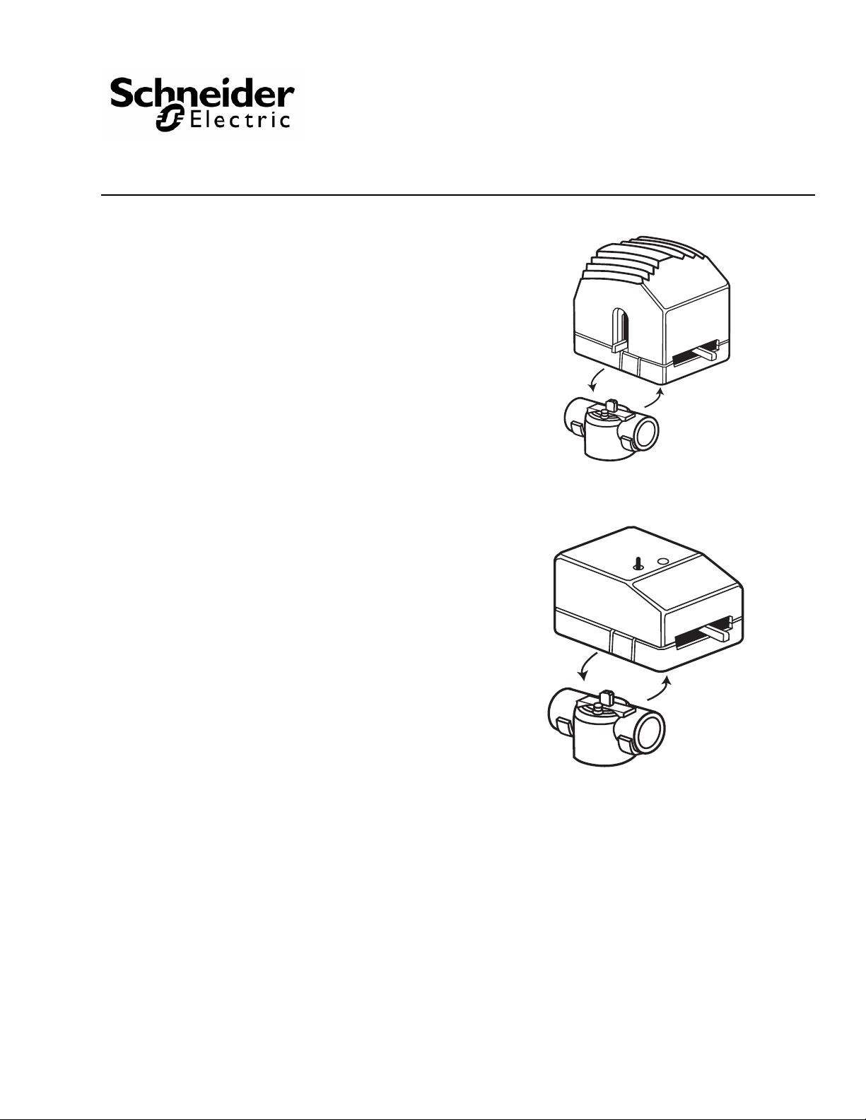
The Modulating PopTop valve assemblies allow the
actuator to be snapped onto, or off from, the valve
body. The actuator can be mounted after the valve
body has been installed into the system without the
need for linkages or calibration.
Available in standard (non-spring return) and spring
return modulating actuators. The two-way spring return
modulating actuators are provided in either normally
open or normally closed operation. The three-way
valves are available in normally closed operation only.
Valve body reversal provides normally open flow for
three-way valve bodies.
Erie VM PopTop Series
Modulating Valves
Floating "T" & Proportional "P"
Standard and Spring Return Modulating Valves
General Instructions
Features
• Magnetic clutch to maxi mize the life of the motor and
gear train
• Manual operating lever/position indicator facilitates
field setup
• Easy to use lever terminal blocks
• Actuator can be installed after the valve body
• Three wire floating and 0 to 10 Vdc or 4 to 20 mA
proportional available
• Spring return will return actuator to normal position
when the power is lost for more than two minutes.
Printed in U.S.A. 2-13 © Copyright 2013 Schneider Electric All Rights Reserved. F-27013-8
Applicable Literature
•
EN-205 Water and S team System Gu idelines, F-26080
Page 2
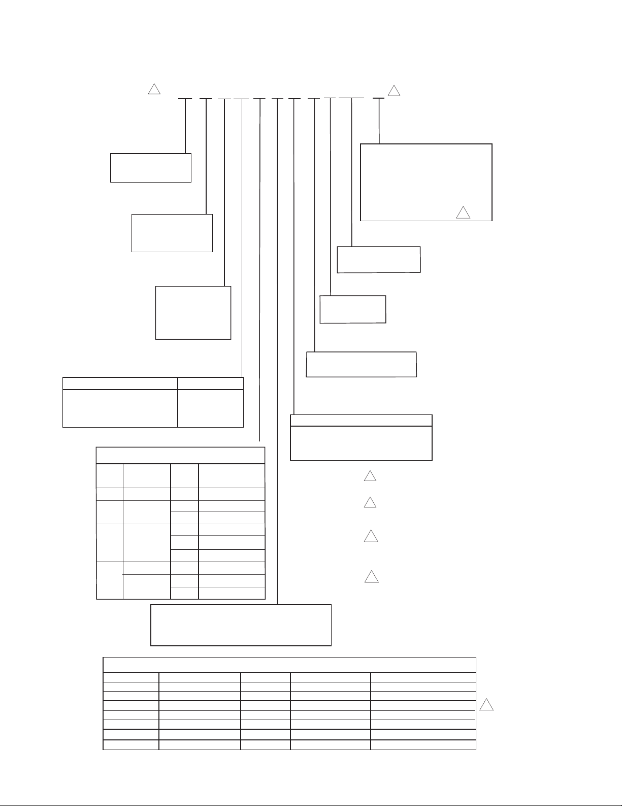
Part Numbering System
Modulating Spring and Non-Spring Return Zone Valves
1
V M X X X X X X 3 A 00 X
Body Type
M = Modulating
Configuration
2 = 2-Way
3 = 3-Way
2 = 1/2"
3 = 3/4"
4 = 1"
5= 1-1/4"
Connection Type Availability
1 = Sweat 1/2", 3/4", 1", 1-1/4"
2 = Threaded NPT 1/2", 3/4", 1"
3 = Threaded Rp (Metric) 1/2", 3/4", 1"
5 = SAE Flare 1/2"
CV Size
1/2" 1, 2, 3, 5
1 = 1.0
1/2" 1, 2, 3, 5
2 = 2.0
3/4" 1, 2, 3
1/2" 1, 2, 3, 5
3 = 4.0
3/4" 1, 2, 3
1" 1
3/4" 1, 2, 3
7 =
1" 1, 2, 3
1-1/4" 1
7.5
8.0
T = Three-wire Floating
P = Proportional, 0-10 Vdc, 0-5 Vdc,
5-10 Vdc or 4-20 mA, Jumper Selectable
Valve Size
Size Connection Type
Actuator Type
2
Options
Non-Spring Return Actuators
0 = No Options
T = Three-Wire Signal Time-Out
Spring Return Actuators
T = Time-Out
Electrical Leads
00 = No leads
Voltage
A = 24 Vac Only
Temperature Ratings
3 = General Temperature
Action
1 = Spring Return Normally closed
2 = Spring Return Normally opened
3 = Non-Spring Return
1
When ordering valve body only: use the first
six positions to configure the valve.
2
When ordering actuator only: use the last
seven positions to configure the actuator.
Prefex with the letter "A."
3
This feature is standard
for spring return actuators.
It must be included in the
part number.
4
Should not be used with thermostats/
controllers unless they have a
timeout feature.
3
Available Actuators
Part Number
AT13A00T
AT23A00T
AT33A000
AT33A00T
AP13A000
AP23A000
AP33A000
2 © Copyright 2013 Schneider Electric All Rights Reserved. F-27013-8
Action
Spring Return
Spring Return
Non-Spring Return
Non-Spring Return
Spring Return
Spring Return
Non-Spring Return
Position
N.C.
N.O.
N.C.
N.O.
Actuator Type
Three Wire Floating
Three Wire Floating
Three Wire Floating
Three Wire Floating
Proportional
Proportional
Proportional
Option
With Time-Out
With Time-Out
None
With Time-Out
None
None
None
4
Page 3
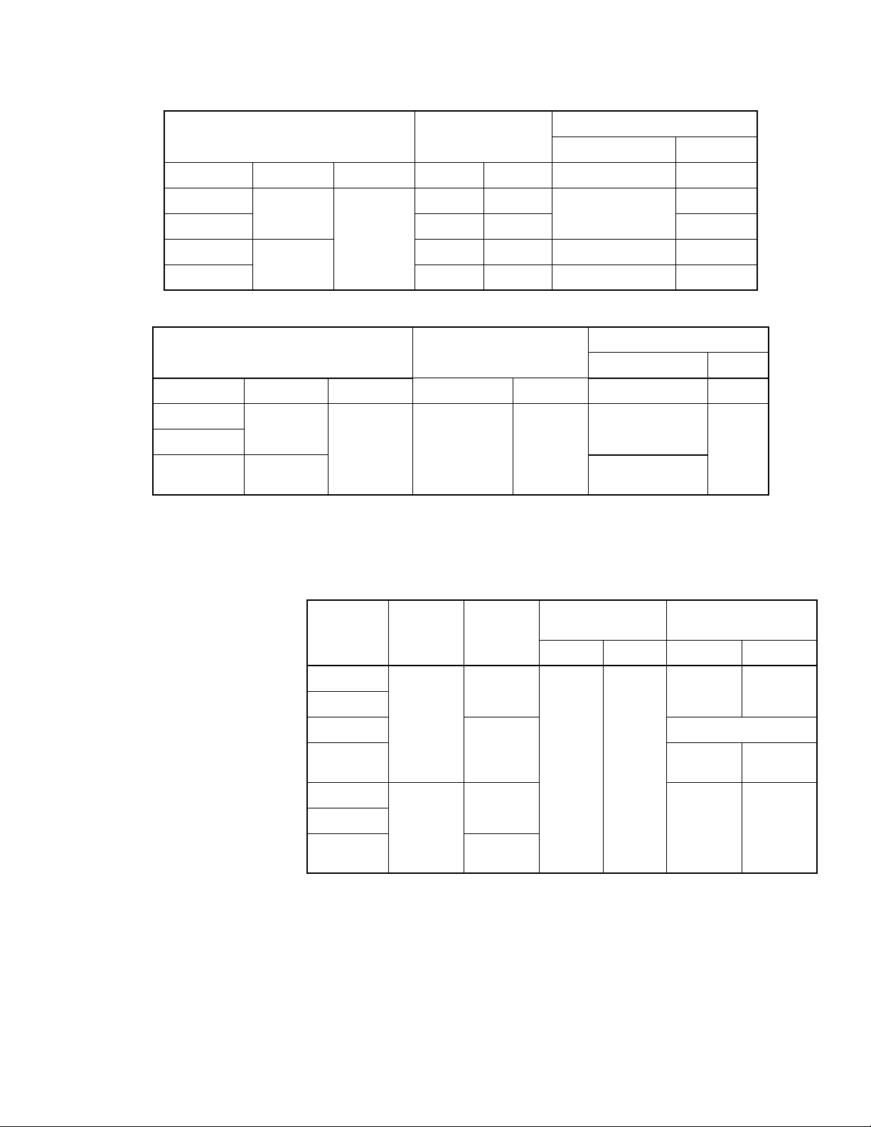
SPECIFICATIONS
Inputs
Floating Actuator Control Circuit, Max.
Powerup Inrush
a
Running
Series Action Vac mA VA VA VA
Total Actuator, Max.
AT13A00T
AT23A00T 24 0.6 1.9
Spring
Return
24 Vac
24 0.6
10
1.9
+25%/-15%
A T33A000
AT33A00T – – 1.2 1.2
a Transformer must be sized for Powerup Inrush
Non- Spring
Return
50/60 Hz
–– 1.0 1.0
To tal Actuator, Max.
Proportional Actuator Control Circuit, Max.
Powerup Inrush
a
Running
Series Action VAC Range Rin VA VA
AP13A000
AP23A000
AP33A000
a Transformer must be sized for Powerup Inrush
b Factory supplied. Actual range is 1-9 Vdc.
Spring
Return
Non-Spring
Return
24 Vac
+25%/-15%
50/60 Hz
b
0-10 VDC
or
0-5 VDC or
5-10 VDC or
4-20 mA
>200K
>200K
>200K
300
10
1.7
1.7
Outputs
Timing:
Nominal Stroke
Series Mode Action
Time
60 Hz 50 Hz 60 Hz 50 Hz
AT13A00T
AT23A00T
AT33A000
Floating
Spring
Return
3 min.
Non-Spring
AT33A00T
AP13A000
AP23A000
AP33A000
Modulating
Return
Spring
Return
Non-Spring
Return
2 min. 30
sec.
3 min.
3 min.
± 30 sec.
2 min.
45 sec.
Mechanical:
Action, T series: Direct acting.
P series: Direct acting (valve opens port B with increase in signal.) Field
selectable reverse acting.
Manual Override, Allows manual positioning.
Operating Pressure Limits, 400 psi (2758 kPa) static pressure.
Material,
Actuator: High temperature plastic.
Valve: Body: Forged brass; stem: nickel- plated/chrome-plated brass; seat:
brass, plug/paddle: high temperature thermoplastic/rubber.
Flow Characteristic, 1.0 to 4.0 Cv: equal percentage. 7.0/8.0 Cv: linear.
Total Run Time
3 min.
36 sec.
no delay
na
3 min.
18 sec.
F-27013-8 © Copyright 2013 Schneider Electric All Rights Reserved. 3
Page 4

Environment
Ambient Temperature Limits:
Shipping & Storage, -40 to 158°F (-40 to 70°C)
Operating, 35 to 125°F (2 to 52°C).
Fluid, 32 to 200× F (0× to 93× C) (not steam rated).
Humidity: 5 to 95% RH, non-condensing.
Seat Leakage: ANSI class IV (0.01%)
Shipping Weight: 1.9 lbs (860 g), actuator and valve body.
Location: NEMA Type 1.
Agency Listings (Actuator Only):
UL873: Underwriters Laboratories (File #E9429 Category Tempera tu re Indicating and
Regulating Equipment) Class 2.
CUL: UL Listed for use in Canada by Underwriters Laboratory. Canadian Standards C22.2
No. 24.
European Community: CE Approved.
Australia: This product meets the requirements to bear the C-Tick Mark according to the
terms specified by the Communications Authority under the Radio Communications Act of
1992.
T ab le-1 Flow Coefficients & Maximum Close-Off Differential Pressu r e.
Valve
Size in.
Connection Type
Flow Coefficient
Cv (kv)
Non-Spring
Operating Mode
(Driven Close)
Maximum Close-Off DP, PSI (kPa)
Spring Return
Operating Mode
(Driven Closed)
Spring Return
Power Failure Mode*
(Spring Close) PSID
1/2 NPT, SW, SAE, Rp 1.0 (0.9) 50 (344) 50 (344) 50 (344)
1/2 NPT, SW, SAE, R p
2.0 (1.8) 50 (344) 50 (344) 20 (138)
3/4 NPT, SW, Rp
1/2 NPT, SW, SAE, R p
4.0 (3.5) 35 (241) 35 (241) 20 (138)3/4 NPT, SW, SAE, R p
1SW
3/4 NPT, SW, Rp 7.5 (6.5) 35 (241) 35 (241) 15 (103)
1SW, Rp
8.0 (6.9) 35 (241) 35 (241) 15 (103)
1-1/4 SW
*If valve is driven closed before a power failure, the "operating mode" close- off pressures apply.
Valve Body Legend
NPT — Threaded
SW — Sweat
SAE — Society Automotive Engineers.
Rp—"Metric" Threaded
4 © Copyright 2013 Schneider Electric All Rights Reserved. F-27013-8
Page 5

TYPICAL APPLICATION (wiring diagram)
Close
COM
Open
J2
100-315
14-28 AWG
J1
C1
Figure-1 Typical Wiring of Three-Wire
Floating Non-Spring Return Valves.
Figure-2 Typical Wiring of Three-Wire Floating
Non-Spring Return Valves with Time-Out.
Figure-3 Typical Wiring of Three-Wire Floating Spring Return Valves with Time-Out.
Figure-4 Typical Wiring of Three-Wire
Proportional Non-Spring Return Valves.
24 Vac
COM
DC In
18-22 AWG
DA
RA
J2
J3
0-10 V
0-5V
5-10V
4-20mA
J4
100-317
J1
Figure-5 Typical Wiring of Three-Wire Proportional
Spring Return Valves.
1
2
1
2
24 Vac
Closed
COM
Open
J2
Close
COM
Open
J1
18-22 AWG
J2
100-316
J1
J3
1
The 24 Vac/COM supply must be
maintained continuously for valve operation.
The valve returns to its normal position
whenever this supply is interrupted.
2
The CLOSE and OPEN control signals
share the COM terminal with the 24 Vac
supply.
100-516
J4
J3
4-20 mA
5-10V
0-5V
0-10V
24 Vac
J1
COM
DC In
J2
RA
DA
J5
100-517
F-27013-8 © Copyright 2013 Schneider Electric All Rights Reserved. 5
Page 6

INSTALLATION
N O T E
N O T E
Inspection
Requirements
Precautions
Inspect the package for damage. If damaged, notify the appropriate carrier immediately.
If undamaged, open the package and inspect the device for obvious damage.
Return damaged products.
• Tools (not provided):
— Wrench 1 to 1-5/8" (if threaded valve)
— Pipe wrench according to pipe size (if threaded valve)
— Soldering equipment (if sweat fit)
— #1 Phillips head screw driver
— Volt-ohm multimeter
• Training: Installer must be a qualified, experienced technician
• Other accessories as appropriate
General
WARNING:
• Electrical shock hazard! Disconnect power before installation to prevent electrical shock
or equipment damage.
• Make all connections in accordance with the electrical wiring diagram and in accordance
with national and local electrical codes. Use copper conductors only.
CAUTION:
• Avoid locations where excessive moisture, corrosive fumes, explosive vapors, or vibra-
tion are present.
• Avoid electrical noise interference. Do not install near large conductors, electrical
machinery, or welding equipment.
Federal Communications Commission (FCC)
This equipment has been tested and found to comply with the limits for a Class B digital
device, pursuant to Part 15 of the FCC Rules. These limits are designed to provide reasonable protection against harmful interference in residential installations. This equipment generates, uses, and can radiate radio frequency energy and may cause harmful interference if
not installed and used in accordance with the instructions. Even when instructions are followed, there is no guarantee that interference will not occur in a particular installation. If this
equipment causes harmful interference to radio and television reception—which can be
determined by turning the equipment off and on—the user is encouraged to try to correct the
interference by one or more of the following measures:
• Reorient or relocate the receiving antenna.
• Increase the separation between the equipment and receiver.
• Connect the equipment to an outlet on a circuit different from that to which the receiver
is connected.
• Consult the dealer or an experienced radio/television technician for help.
Canadian Department of Communications (DOC)
This class B digital apparatus meets all requirements of the Canadian Interference-Causing
Equipment Regulations.
European Standard EN 55022
WARNING:
This is a class B (European Classification) product. In a domestic
environment this product may cause radio interference in which case the
user may be required to take adequate measures.
6 © Copyright 2013 Schneider Electric All Rights Reserved. F-27013-8
Page 7

Mounting
360
Figure-6 Mounting.
Figure-7 Two-Way Spring Return Valves.
The Modulating PopT op Series valves can be mounted in horizontal or vertical piping. When
installed in horizontal piping, the actuator must be above the valve body. Refer to Figure-6.
85
Piping
Refer to the piping diagrams in Figure-7 fo r two-way valves. For three-way valves refer to
Figure-8.
• The 3-way is only configured as normally closed. For normally open configuration to the
coil turn valve around. For proportional valves, set the control action (direct or reverse
accordingly).
WARNING:
• The valve should be used in a closed loop system.
• All valves must be piped so that the plug closes against the direction of flow. For two-way
valves, flow is from port B to port A. For normally closed three-way valves, B is the service
port and A is the bypass port. For normally open three-way valves. A is the service port
and B is the bypass port.
• Three-way VM valves must be piped in a mixing configuration, not diverting.
B
COIL
Normally Open
A
Normally Closed
B
COIL
A
F-27013-8 © Copyright 2013 Schneider Electric All Rights Reserved. 7
Page 8

Spring Return
Figure-8 Three-Way Spring Return Val v es.
Figure-9 Three-Way Spring Return Valves.
Normally Closed
Spring Return
Normally Open
B
COIL
A
A B
COIL
Sweat End Valves
1. Slowly position the actuator’s manual operating lever (on the front of the actuator) to the
middle position, to manually open the valve so that the plug is not in contact with the
valve body.
CAUTION:
• The plug inside the valve is made of a plastic material. It may be damaged by heat con-
ducted through the valve body if it remains seated against its port during soldering. Be
sure to manually open the valve before soldering to prevent damage.
• If the manual operating lever does not move freely for manual positioning, the solenoid
may have latched during shipping. Do not force the lever. Instead, first unlatch the solenoid by placing the red manual solenoid latch lever (on the side of the actuato r ) in the
"Up" position, then placing the manual o perating lever in the middle position.
2. With the valve in the mid-position, latch the solenoid by placing the manual solenoid
latch lever in the "Up" position. Then, detach the actuator by depressing the release button and pulling it away from the valve body (Figure-9).
CAUTION:
• Be sure to remove the actuator from the valve body before soldering, to avoid damage to
the actuator and to ease the soldering process.
• Use only lead or tin based solder with a melting point below 600×F (315×C).
Solenoid Latch
Lever
Release
Button
Pin Mating Hole
Stem
Pin
3. Thoroughly clean the ends of the water supply tubing for a minimum distance of 1 inch
(25 mm) from the end, so that a good joint can be made in the shortest time and without
an excessively large flame.
8 © Copyright 2013 Schneider Electric All Rights Reserved. F-27013-8
Manual Opening
Lever
Stem Mating Hole
Page 9

4. Solder the valve body in place, directing the flame tip away from the valve and taking
N O T E
N O T E
N O T E
N O T E
care not to overheat the joint area. When finished, cool the valve quickly with a wet
cloth.
The valve body may be submerged in water, or pressurized, for leak testing before
reattaching the actuator.
5. Reinstall the actuator according to "Reattaching the Actuator to the Valve Body."
NPT and Rp Threaded Valves
When installing threaded valves, the actuator should be detached from the valve body to
ease installation. To do so, first slowly move the actuator’s manual operating lever (on the
front of the actuator) to the middle position. Then latch the solenoid by placing the red
manual solenoid latch lever on the side of the actuator to the "Up" position. Finally detach
the actuator by depressing the release button and pulling the actuator away from the valve
body (Figure-9).
1. Apply teflon tape to all but the last two threads on the end of a properly threaded,
reamed, and cleaned pipe. Make sure that pipe chips, scale, etc. do not get into the pipe
since this material may lodge in the valve seat and prevent proper closing and opening
of the valve.
2. Start the joint by hand-screwing the pipe to the valve. If the thread engages normally,
turn the pipe by hand as far as it will go.
3. Use a wrench to fully tighten the valve to the pipe using the flats located on the valve
body ports. Take care not to over-tighten or strip the threads.
4. Reinstall the actuator according to "Reattaching the Actuator to the Valve Body."
Reattaching the Actuator to the Valve Body
1. Before reinstalling the actuator, be sure that its manual operating lever is in the midposition, and that the solenoid is latched. The solenoid is latched when the manual
solenoid latch lever is in its "Up" po si ti on (Figure-9).
2. Depress the release button.
3. Align the valve body with the actuator to ensure the stem is inserted into the large mating hole on the bottom side of the actuator (Figure-9).
4. Engage the actuator on the body and release the button.
Wiring
• Multiple actuators may be connected to a single controller, up to the current rating of the
controller and transformer. Do not exceed the maximum current draw of the controller.
• Use of a properly sized, inherently limited, Class 2 transformer is recommended.
• Use only 18 to 24 AWG copper wire for all connections.
• The return spring feature is primarily a safety feature. It is recommended that the spring
return feature is not used for routine, normal operation.
Three-wire Floating
• The three-wire floating spring return valve includes a time-out feature that automatically
turns off the control signal to the valve after a pre-determined period of continuous operation. This time period is three minutes at 60 Hz and 3.6 minutes at 50 Hz.
• Spring return valves feature a two second time delay upon power loss, to prevent the loss
of valve position during brief outages. There is a three second delay at power-up.
1. Remove the cover from the actuator, then connect the power and control wiring to the
terminal block (Figure-1 and Figure-3).
2. Reinstall the cover onto the actuator.
F-27013-8 © Copyright 2013 Schneider Electric All Rights Reserved. 9
Page 10

N O T E
N O T E
INITIAL SETUP
Application Notes
Proportional
If multiple proportional valves are used on a single 4 to 20 mA loop, each valve must have
its own isolation transformer.
1. Remove the cover from the actuator, then connect the power and control wiring to the
terminal block (Figure-4 and Figure-5).
All units are shipped with the actuator in the direct-acting, 0 to 10 Vdc mode, which means
that the valve opens the B port upon receiving an increasing Vdc control signal. To change
the action to reverse-action (valve closes with an increase in control signal), simply remove
the action jumper J2 and relocate it to the reverse-acting pins. See Figure-4 and Figure-5.
2. Reinstall the cover onto the actuator.
These valves are designed for application to closed hydronic heating and cooling systems.
Use in systems which have substantial make-up water (open systems) is not recommended.
High levels of dissolved oxygen, chlorine, and debris that may be found in open systems can
attack the valve materials and result in premature failure.
3-Wire Floating "T" Type
The controller or thermostat used to operate the "T" type must be configured to turn off the
control signal after being on continuously for three minutes.
3-Wire Floating Time Out "T" Option
If the control system used does not have the ability to limit the running time, then the time
out option must be utilized, which automatically cuts off the control signal to the valve after
three minutes of continuous operation. This is standard on the spring return, and is an option
on the non-spring return.
Proportional "P" Type
Multiple "P" valves may be connected to a single controlle r, up to the current rating of the
controller and transformer. For 4-20 mA control, a separate isolation transformer must be
used with each valve. The actuator is also provided with a jumper to allow the action to be
reversed. All units are shipped with the actuator in the DA (direct acting) mode, which means
that the valve opens the B port upon receiving an increasing control signal. To change the
action to reverse action (valve closes upon receiving an increasing control signal), simply
remove the action jumper and relocate it to the RA (reverse acting) pins.
CHECKOUT
1. Make sure the valve operates freely before installing the valve.
2. If the stem does not operate freely it may indicate that the stem was damaged and may
require that the valve be repaired or replaced.
3. After the piping is under pressure check the valve body and the connections for leaks.
4. After the valve and actuators are installed power the actuator and check the operation.
a. For two-way model:
Power the valve to the close position (per label), and the "B" port should be closed.
b. For three-way model:
Power the valve to the open position (per label), and the "A" port should be closed.
c. For Spring Return model:
Removing power should return the actuator to its normal position.
10 © Copyright 2013 Schneider Electric All Rights Reserved. F-27013-8
Page 11

THEORY OF OPERATION
Figure-10 Modulating Non-Spring Return Valve.
3-3/16
(81)
MAINTENANCE
FIELD REPAIR
DIMENSIONAL DATA
The PopT op Series floating or proportional modulation valves are modulating valve actuator
assemblies. The modulating valves are designed to control the flow in the circuit by making
incremental adjustments to the flow path with-in the valve.
The Spring Return PopT op Series modulating valves, when powered, the actuator moves to
the desired position, at the same time tensing the spring return system. When power is
removed for more than two minutes the spring returns the actuator to the normal position.
The Modulating PopTop Series valves require no maintenance. Replace defective modules
Regular maintenance of the total system is recomended to assure sustained, optimum
performance.
Replace any damaged or failed components with complete bodies or actuator replacements.
4-1/4
(107)
3-13/16
(98)
3/16
(4)
1/8
(2)
Ta ble-2 Dimensions - inches (mm).
Valve Body Size A B C
1/2" Sweat 1-5/16 (33) 15/16 (23) 1-5/16 (33)
3/4" Sweat 1-3/8 (35) 15/16 (23) 1-11/16 (43)
1-1/4" Sweat 1-7/8 (47) 1 (25) 1-13/16 (46)
1/2" NPT, Rp 1-3/8 (35) 15/16 (23) 1-5/16 (33)
3/4" NPT, Rp 1-11/16 (43) 15/16 (23) 1-7/16 (37)
1" NPT, Rp 1-7/8 (47) 1 (25) 1-11/16 (43)
1/2" SAE Flare See Figure-12
2-1/4
(57)
3-3/16
(81)
1-5/8
(41)
B
C
2-Way
3-Way
A
2
(51)
1-9/16
(39)
1-3/16
(31)
A
1" Sweat 1-11/16 (43) 15/16 (23) 1-11/16 (43)
F-27013-8 © Copyright 2013 Schneider Electric All Rights Reserved. 11
Page 12

3-7/8
Figure-11 Modulating Spring Return Valve.
4-3/4
(121)
4-1/4
(108)
15/16 (24)
2-Way
1-5/16
(33)
3-Way
3-7/8
(98)
1-1/4
(33)
4-9/16
(116)
2-5/16
(58)
3-11/16
(94)
4-3/4
(121)
1-9/16
(40)
1-3/16
(30)
1-9/16
(40)
Figure-12 1/2" SAE.
(98)
4-1/4
(107)
3-11/16
B
2-Way
(93)
4-3/4
(121)
C
3-Way
1/16
(1)
1-9/16
(40)
AA
2
(51)
1-9/16
(39)
1-3/16
(31)
© Copyright 2013, Schneider Electric
All brand names, trademarks and registered
trademarks are the property of their respective
owners. Information contained within this
document is subject to change without notice.
F-27013-8
 Loading...