

Page 1
Application
O
f
f
M
e
d
C
o
o
l
H
i
H
e
a
t
L
o
w
T155
The T155 series thermostat provides on/off control for
low voltage and line voltage valves, relays and fan
motors. Applications include two pipe and four pipe fan
coil units, ventilators and air quality operations.
Features
• Manual or automatic changeover models
• Line voltage 3-speed fan control
• Continuous or cycling fan operation (cycling fan
operation requires additional relay or relays)
Schneider Electric Erie T155
Series
Non-Digital, On/Off Thermostat
General Instructions
• Remote sensor capability for seasonal changeover
• Handles all supply voltages from 24 to 277 Vac at
50/60 Hz (fan and system voltage must be the same)
Printed in U.S.A. 6-10 Copyright 2010 Schneider Electric All Rights Reserved. F-27022-3
Page 2
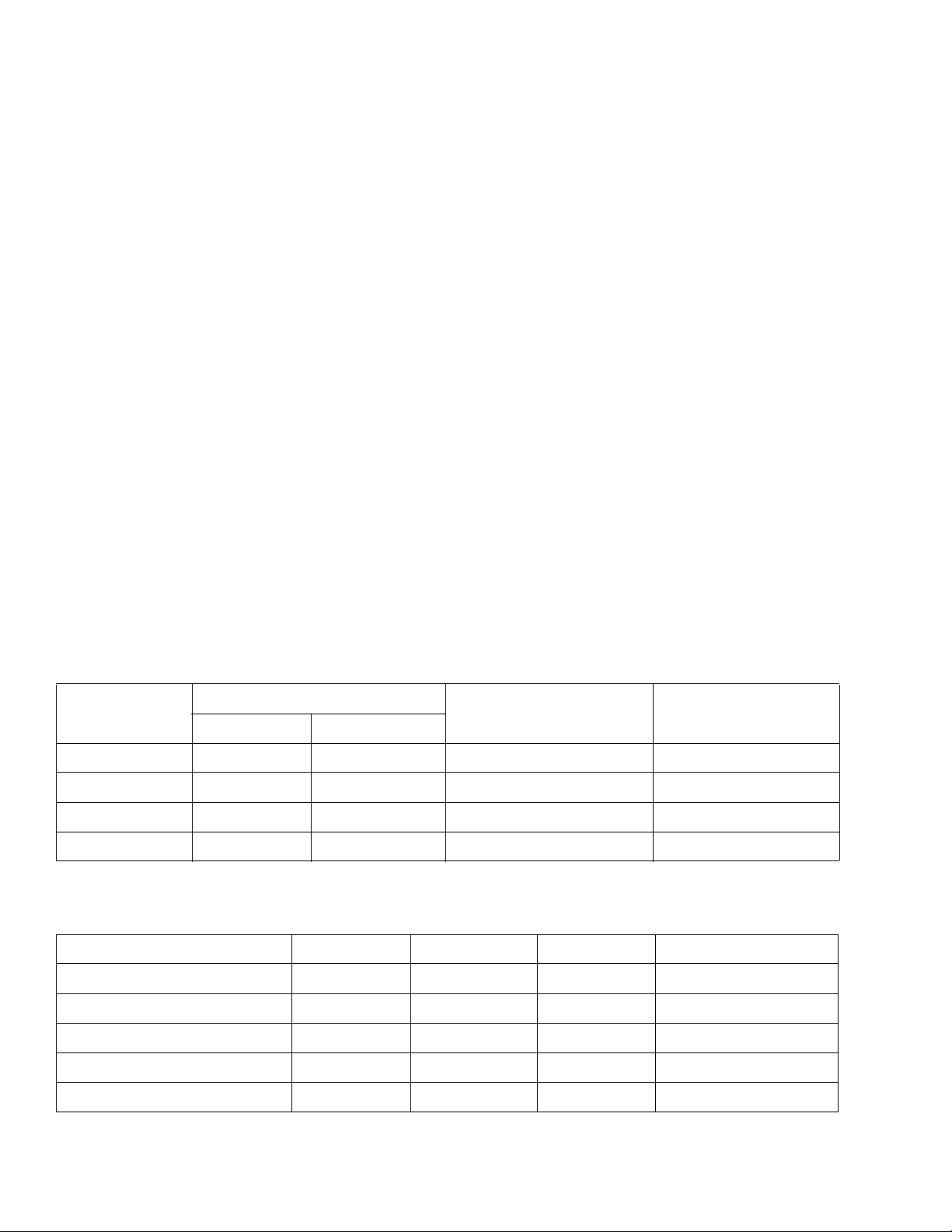
SPECIFICATIONS
Inputs
Outputs
Control
Enclosure
Environment
Power Input: 24 to 277 Vac @ 50/60 Hz. Power Consumption: 0.88 watts at maximum. Connections:
Power, Up to 14 AWG wire.
Control, Up to 14 AWG wire.
Electrical:
Heat/Cool Output Rating, Pilot Duty, 10 VA at 24 Vac, 20 VA at 120 -277 Vac.
Fan Switch, Refer to Table-1
Deadband (TB155 Auto Changeover Models Only): 4F degrees (2.2C degrees).
Deadband (TA155-017 and TA155-018): 0F degrees (0C degrees).
Operating Differential: 1F degrees (0.6C degrees).
Setpoint Adjustment Range: 50 to 90F (optional dial, 10 to 32C).
Material, Rigid vinyl. Finish, Cool gray.
Temperature Limits:
Shipping & Storage, -30 to 130F (-34 to 55C).
Operating, 32 to 130°F (0 to 55°C). Shipping Weight: 0.31 lbs (140 g). Location: NEMA Type 1.
Agency Listings
CE: Compliant.
Table-1 Fan Switch Current Ratings (Amps).
Inductive
Volt ag e
FLA LRA
24 N/A N/A N/A 24 VA
120 5.8 34.8 6.0 125 VA
240 2.9 17.4 5.0 125 VA
277 2.4 14.4 4.2 125 VA
a Fan and system must share the same voltage.
Table-2 Model Chart.
Model Outputs Changeover Fan Control System Switches
TA155-010 Dual Manual Hi-Med-Lo Heat-Off-Cool
TA155-017 Single N/A Hi-Med-Lo On-Off
TA155-018 Single N/A None None
TB155-010 Dual Automatic
TB155-015 Dual Automatic
a
Resistive Amps Pilot Duty
a
a
Hi-Med-Lo On-Off
None None
a Automatic changeover models have a 4F degree deadband between heating and cooling.
2 Copyright 2010 Schneider Electric All Rights Reserved. F-27022-3
Page 3
Accessories
4
3
2
1
1
2
3
TB1
TB3
L1 (HOT)
COOLING
VALV E
L2 OR NEUTRAL
TA155-018
(FOR HEATING ONLY, WIRE TO TB3, #1)
4
3
2
1
1
2
3
1
2
3
4
5
TB1
TB2
TB3
HEATING/
COOLING
VALVE
L2 OR NEUTRAL
TA155-017
680-243
CHANGEOVER
THERMOSTAT
PIPE MOUNTED
WHT
BLK
BLU
LOW
MED
L1 (HOT)
FAN
HI
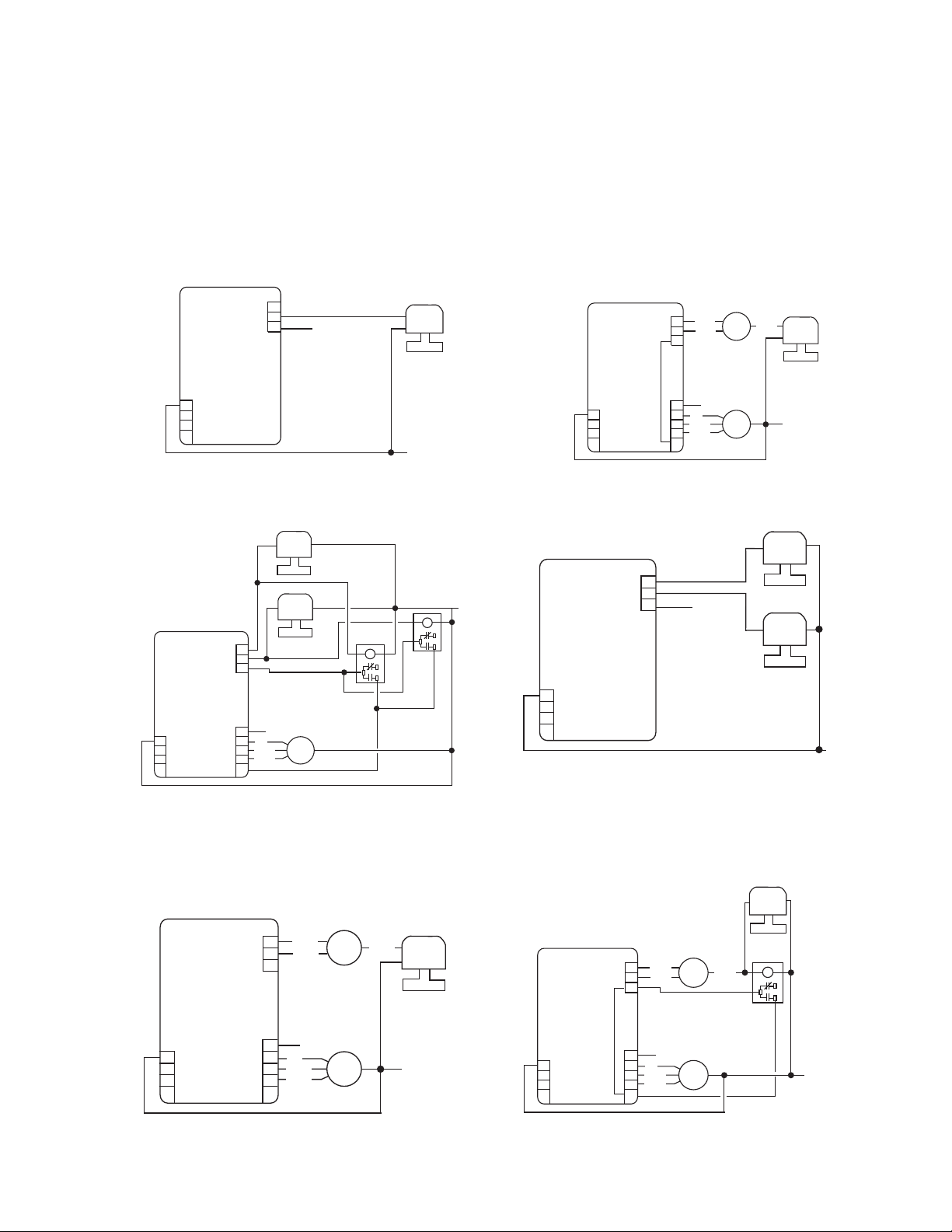
Figure-1 Typical 2-Pipe Cooling or Heating Only.
No Fan Connections.
Figure-2 Typical 2-Pipe Heating/Cooling/Continuous Fan
with System Switch off, Fan is Off.
4
3
2
1
1
2
3
1
2
3
4
5
TB1
TB2
TB3
COOLING
VALVE
HEATING
VALVE
L2 OR NEUTRAL
TA155-010
LOW
MED
L1 (HOT)
FAN
HI
FAN
RELAY
FAN
RELAY
Figure-3 Typical 4-Pipe Heating/Cooling Fan cycles with
Demand for Heating or Cooling. With System Switch Off,
Fan is Off.
Figure-4 Typical 4-Pipe Heating/Cooling.
No Fan Connections.
/
Figure-5 Typical 2-Pipe Heating/Cooling Fan Runs
with System Switch On or Off.
Figure-6 Typical 2-Pipe Heating/Cooling Fan Cycles
with Demand for Heating or Cooling.
With System Switch Off, Fan is Off.
Wiring
65345 4-3/4” X 4-3/4” adapter plate.
65406 Remote or changeover sensor, 60" leads 10k @ 77F (25C).
65409 Fahrenheit set point dial 50 to 90F
65410 Celsius set point dial, 10 to 32C.
65170 Warmer/cooler set point dial.
65860 Set point dial stop kit. Limits dial travel in 2F degree increments.
680-243-5 Auto seasonal changeover switch.
680-243-6 Auto seasonal changeover switch.
TA155-017
TB3
TA155-015
TB3
1
2
3
TB1
4
3
2
1
680-243
CHANGEOVER
THERMOSTAT
PIPE MOUNTED
BLK
1
2
BLU
3
WHT
HEATING
COOLING
VALV E
TA155-017
TB3
1
2
3
BLK
BLU
L1 (HOT)
680-243
CHANGEOVER
THERMOSTAT
PIPE MOUNTED
WHT
HEATING
COOLING
FAN
RELAY
VALV E
VALV E
HEATING/
COOLING
VALV E
L2 OR NEUTRAL
TB2
TB1
4
F-27022-3 Copyright 2010 Schneider Electric All Rights Reserved. 3
2
1
3
1
2
3
4
5
HI
MED
LOW
L1 (HOT)
FAN
TB2
L2 OR NEUTRAL
TB1
4
3
2
1
L1 (HOT)
1
2
HI
MED
LOW
FAN
L2 OR NEUTRAL
3
4
5
Page 4

t W A R N I N G
t C A U T I O N
Tb155-010
Figure-7 Typical 4-Pipe Heating/Cooling Fan Runs
Continuously with System Switch On.
With System Switch Off, Fan is Off.
TB3
HEATING
VALV E
1
2
3
COOLING
VALV E
INSTALLATION
Inspection
Requirements
Precautions
TB1
4
3
2
1
TB2
L1 (HOT)
1
2
HI
MED
3
LOW
4
5
FAN
L2 OR NEUTRAL
Inspect the package for damage. If damaged, notify the appropriate carrier immediately.
If undamaged, open the package and inspect the device for obvious damage.
Return damaged products.
• Tools (not provided)
— Screwdriver
— Volt ohm multimeter
• Training: Installer must be a qualified, experienced technician
• Other accessories as appropriate
General
Mounting
• Electrical shock hazard! Disconnect power before installation to prevent electrical shock
or equipment damage.
• Make all connections in accordance with the electrical wiring diagram and in accordance
with national and local electrical codes.
• Avoid electrical noise interference. Do not install near large conductors, electrical machin-
ery, or welding equipment.
• Avoid locations where excessive moisture, corrosive fumes, vibration, or explosive vapors
are present.
Mount the T155 series to a standard 2 x 4 in. electrical box. Refer to Figure-8. If mounting
to 4 x 4 in. electrical box use adapter plate (#65345). Standard holes are provided for
mounting purposes. Mount the thermostat five feet above the floor on an inside wall. Do not
mount near a heat source (lamp or sunlight), or behind a door or furniture. Do not mount on
a surface that exceeds 130F (55C). Insulate behind thermostat if necessary to protect it
from cold or warm air from outside areas.
4 Copyright 2010 Schneider Electric All Rights Reserved. F-27022-3
Page 5

Wiring Notes
Figure-8 Mounting.
Seasonal Changeover Sensor
When installing the seasonal changeover sensor strap on the sensor to the main coil input
or a pipe that will determine the fluid temperature of the coil. If a well is available use thermal
grease for a faster temperature response. Insulate the entire sensor and pipe two inches
before and after the sensor for a total of approximately six inches. This insulation is used to
decrease the affect of ambient temperature upon the sensor.
Remote Sensor
Install the sensor in a location that will measure only the temperature to be sensed without
any external heating or cooling sources influencing the sensor. Examples of sources to avoid
are direct sunlight, mounting the sensor too high or too low on a wall, or any areas in ducts
that have dead air movement or un-mixed air. Be aware of room stratification and air
movement when determining the sensor location.
When using the optional remote sensor, remove pin pair jumper cap JP1 (Figure-9).
Removing jumper JP1 disables the onboard sensor. Failure to remove jumper JP1 will
provide two sensor inputs. The thermostat will not function properly. Run the remote sensor
wiring away from any electrical motors or power wiring. Failure to do so may result in poor
thermostat performance due to electrical noise.
An external line voltage relay is not need with 3-speed fan applications unless the current
exceeds the values noted in Table-1. System and fan switch voltage must be the same.
For fan cycling operation with a call for heating or cooling, a fan relay needs to be inserted.
For a two pipe heating and cooling application, an external auto seasonal changeover switch
(680-243-6) must be connected to TB3-1 and TB3-2. This assures proper control depending
on the temperature of the controlling media.
In all applications run the sensor wire away from any electronic noise generating devices,
such as motors, fluorescent lights and microwaves. Do not run in parallel to line voltage
wiring. The maximum length of non-shielded sensor wire should not exceed 25 ft. Even if the
sensor wire is not near any noise generating devices, it still acts like an antenna and picks
up background noise that may affect the temperature measurement.
In an electronic noisy environment or if the sensor wire must be close to noise generating
devices, always use shielded wire and connect the shielding to an earth ground. Avoid
electronic noise generating devices even if using shielded cable. The shielded sensor wire
should not exceed 100 ft. in length and should be properly grounded.
F-27022-3 Copyright 2010 Schneider Electric All Rights Reserved. 5
Page 6

Terminal Description
Figure-9 Terminal Definitions.
CHECKOUT
CONNECTIONS
Terminal Block 3
1 Heat
2 Cool
3 Sw'd power
Terminal Block 2
1 L1
2 High
3 Med
4 Low
5 Fan hot
Terminal Block 1
4 L2 or neutral
3 No connection
2 Remote sensor
1 Remote sensor
TB1
TB3
TB2
JP1
1. Verify the system voltage.
2. Make sure the fan switch and the system switch voltages are the same.
3. If a transformer is being used make sure it is large enough to support the current demands of all controls wired to the transformer.
4. Make sure devices being controlled do not exceed the power handling ability of the T155. Refer to Table-1 for current handling specifications.
5. If a remote sensor (thermistor) is in use, make sure pin pair jumper cap, JP1, has been removed.
6. When verifying system operation connect a voltmeter in parallel across the heat output
terminal, TB3-1, and common terminal, TB1-4. Read the meter to verify whether the
output is powered when it should be. In cooling mode check for voltage across cooling
terminal, TB3-2 and common terminal, TB1-4.
THEORY OF OPERATION
All T155 models are electronic thermostats. A variable resistance device called a thermistor
senses the room temperature and sends a resistance value to the T155. For example: in
heat mode, the T155 measures the temperature represented by the resistance value of the
onboard thermistor (or remote thermistor if used). If the sensed temperature value drops 1F
(0.6C) or more degrees below the set point the heating output will be powered. A valve or
damper opens to heat the space. When the temperature reaches the set point the heating
output will be turned off, closing the valve or damper. The 155 series thermostats maintain
temperatures with a 1F (0.6C) degree differential in both heating and cooling.
MAINTENANCE
The T155 series requires no maintenance. Replace defective units.
Regular maintenance of the total system is recommended to assure sustained, optimum
performance.
FIELD REPAIR
None. Replace any damaged or failed units with functional replacements.
6 Copyright 2010 Schneider Electric All Rights Reserved. F-27022-3
Page 7

DIMENSIONAL DATA
Figure-9 T155 Series.
Figure-10 Adapter Plate.
Figure-11 Remote Sensor/Change Over Sensor.
2-3/4
(70)
(25)
1
4-1/2
(114)
3-5/16
(84)
2-1/8
(53)
11/32
(9)
1/2
OPENING
FOR WIRING
MOUNTING SLOTS (2)
(13)
5/32 X 3/8 REF.
(4 X 100)
4-3/4
(120)
3/16 (5) DIA.
BLIND HOLE
10 PLACES
1-13/16
(46)
1-13/16 (46)
3-1/4 (83)
4-3/4 (120)
WALL PLATE (BACK VIEW)
1/8 (3) DIA. BLIND HOLE
2 PLACES
3-1/4
(83)
F-27022-3 Copyright 2010 Schneider Electric All Rights Reserved. 7
Page 8

October 1st, 2009, TAC became the Buildings business of its parent company Schneider Electric. This document reflects the visual identity of Schneider Electric,
On
however there remains references to TAC as a corporate brand in the body copy. As each document is updated, the body copy will be changed to reflect appropriate
corporate brand changes.
Copyright 2010, Schneider Electric
All brand names, trademarks and registered
trademarks are the property of their respective
owners. Information contained within this
document is subject to change without notice.
F-27022-3
 Loading...