

Page 1
b
u
b
u
4
USB
Char ger
Surge Protection
Outle ts
bu452a
USB Data Port
(PowerChute)
AC Power
In let
Circuit
Breaker
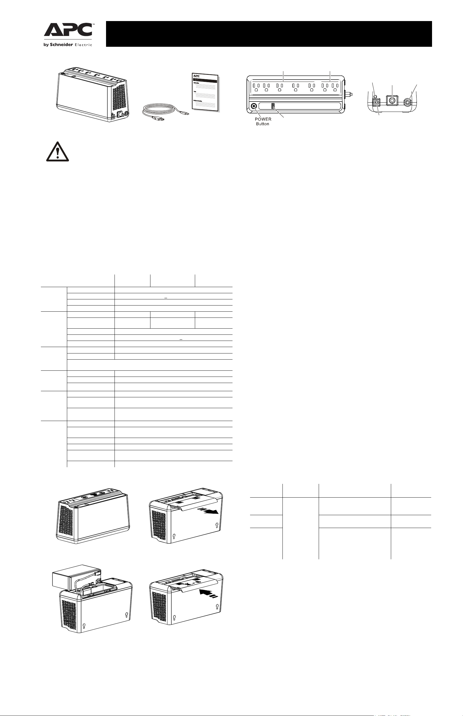
User Manual Back-UPS™ BE600M1, BN650M1/650M1-CA/675M1
Inventory
b
u
4
4
6
a
Safety and General Information
SAVE THESE INSTRUCTIONS - This section contains
important instructions that should be followed during
installation and maintenance of the UPS and batteries.
• This UPS is intended for indoor use only.
• Connect the Back-UPS power cable directly to a wall outlet. Do not use surge
protectors or extension cords.
• Replace batteries only with APC by Schneider Electric approved batteries (see
Replace Battery section for details)
• When grounding cannot be verified, disconnect the equipment from the utility
power outlet before installing or connecting to other equipment. Reconnect the
power cord only after all connections are made.
CAUTION
• Do not dispose of batteries in a fire. The batteries may explode.
• Do not open or mutilate batteries. Released electrolyte is harmful to the skin and
eyes. It may be toxic.
• Before replacing batteries, remove conductive jewelry such as chains, wrist
watches, and rings. High energy through conductive materials could cause severe
burns.
Specifications
Model
Input
Output
USB
Port
Protection
and
Filtering
Battery
Physical
Vo l t a g e 1 2 0 Va c Nominal
Frequency 50/60 Hz +
Brownout Transfers 92 Vac Typical
Over-voltage Transfer 139 Vac Typical
UPS Capacity 600 VA, 330 W 650 VA, 360 W 675 VA, 360 W
Total Amperage (AC
outlets)
Voltage - On Battery 115 Vac ± 8%
Frequency - On Battery 50/60 Hz +
Transfer Time 6 ms Typical, 10 ms maximum
* Charging Current 1.5A
Charger compatibility USB Battery Charging Specification 1.2
* Pow
er output is dependent power drawn by the connected device. Check your devi
nufacturer to understand the maximum charging current for a given USB spec
ma
AC Surge Protection Full time, 490 Joules
EMI/RFI Filter Full time
AC Input Resettable circuit breaker
Type Sealed, maintenance-free, lead acid 12V
Average Life 3 - 5 years, the number of discharge cycles and environmental
Charging Time
Net Weight 7.7 lb (3.5 kg)
Dimensions
LxWxH
Operating Temperature 32º F to 104º F (0º C to 40º C)
Storage Temperature 5º F to 113º F (–15º C to 45º C)
Operating Relative
Humidity
Operating Elevation 0 to 10,000 ft (0 to 3000 m)
BE600M1 BN650M1/
10 hours. Using the USB ports while charging the battery will
Connect the Battery
The Back-UPS is shipped with one battery cable disconnected.
7
4
4
u
b
Remove the “Stop! Connect the Battery”
label that covers the outlets.
9
4
4
u
b
Connect the battery cable securely to the
battery terminal. It is normal for small
sparks to be seen when the battery cable is
connected to the battery terminal.
BN675M1
BN650M1-CA
3Hz auto-sensing
5.0A 5.42A 5.63A
1
temperature
increase the amount of time required.
10.8 in x 4.1 in x 5.5 in
27.4 cm x 10.5 cm x 13.9 cm
0 to 95% non-condensing humidity
a
4
Press the battery compartment cover
release tabs located on the underside of
the unit. Slide the battery cover off.
a
Reinstall the battery compartment
cover. Be sure that the release tabs lock
into place.
Connect Equipment
Battery Backup + Surge
Protection Outlets
Building
Wiring
Fa ult
bu451a
Battery Backup + Surge Protection Outlets
Battery backup outlets provide protection to connected equipment when the
Back-UPS is turned on and connected to AC power. Battery backup outlets receive
power from the battery for a limited period of time when a power outage, or brownout
condition occurs. Battery backup outlets provide protection from power surges or
spikes. Connect a computer, monitor and other peripheral devices to these outlets.
Surge Protection Outlets
Surge protection outlets provide protection to connected equipment when the
Back-UPS is connected to AC power, and is switched on or off. Surge protection
outlets provide protection from power surges or spikes. Connect peripheral devices
(such as printer, scanner, etc.) that do not need to remain on during power outages or
AC problems to the surge protection outlets.
USB charging port
The USB port provides a maximum of 1.5A DC power. The USB port will provide
power when the unit is on AC and on battery.
Turn On the Back-UPS
Press the POWER button located on the top of the Back-UPS. The POWER button
will illuminate green and a single short beep will indicate that the Back-UPS is on and
providing protection for connected equipment.
The Back-UPS battery charges fully during the first 24 hours while connected to AC
power. The Back-UPS battery will charge regardless of whether the Back-UPS is
switched on or off as long as it is connected to AC power. The UPS will have full
runtime capability after the initial 24 hour charging period.
If the red Building Wiring Fault indicator (located on the end near the power cord) is
lit, your building wiring may present a shock hazard that should be corrected by a
qualified electrician.
Turn Off the Back-UPS
To turn off the Back-UPS, press the POWER button for at least 2 seconds. At the first
beep, release the button and the UPS will turn off. A 2 second delay has been added to
mitigate unintentional contact with the POWER button.
ce
.
Quick Mute
The Back-UPS is able to temporarily mute user correctable alarms such as: On
Battery, Battery disconnected and Overload.
During such alarms, a short press (less than 2 seconds) of the POWER button will
temporarily mute the alarm until the condition has been reset. A short double beep will
confirm that Quick Mute has been activated. Pressing the POWER button for more
than 2 seconds will turn off the UPS.
Other critical events such as Battery replacement and Charger notification can not be
temporarily muted. The unit in these cases must be turned off.
On Battery Indicator Modes
This Back-UPS has 3 On Battery Indicator modes provided that the UPS is turned on.
To configure an On Battery Indicator mode, hold down the POWER button and wait
for the third beep. At the third beep the POWER button will cycle red / green. Release
the POWER button and its color will indicate the mode the UPS is in. Press the
POWER button to cycle through each mode. See the table below for the mode
selection colors. Once the mode has been selected, wait 5 seconds and the setting will
be committed to the UPS.
Mode
Quiet Alarm
(default)
No Alarm No alarm while the UPS is On
a
8
4
Full Alarm Alarm sounds 4 beeps every 30
Visual
Indicator
The POWER
button is solid
green and flashes
twice every 2
seconds until
Low Battery
notification
where it will
flash green in
rapid succession.
Audible Indicator
No alarm until Low Battery
notification where the alarm beeps
twice every 30 seconds
Battery
seconds until Low Battery
notification where the alarm beeps
every half second. As the UPS shuts
down it sounds one beep every 4
seconds
Mode Selection
Color
Flashing green
Flashing red
Flashing amber
PowerChute™ Personal Edition Software
Overview
Use PowerChute Personal Edition software to configure the UPS settings. Protect
your computer and other equipment during a power outage. During a power outage,
PowerChute will save any open files on your computer and shut it down. When power
is restored, it will restart the computer.
a
0
5
Note: PowerChute is only compatible with a Windows operating system. If you are
using Mac OSX, use the native shutdown feature to protect your system. See the
documentation provided with your computer.
Installation
Use a USB cable to connect the Data port on the rear panel of the UPS to the USB port
on your computer. On the computer, go to www.apc.com/tools/download. Select
“Software Upgrades - PowerChute Personal Edition” in the “Filter by Software/
Firmware” drop down menu. Select the appropriate operating system. Follow
directions to download the software
.
Page 2

Status Indicators
Wall-mounting Template
b
u
3
8
214 mm
8.43 in.
Troubleshooting
St
atus
Power On
The Back-UPS is supplying AC
power to connected equipment.
On Battery
Back-UPS supplying battery
power to battery backup outlets.
Low Battery notification
The Back-UPS is supplying
battery power to the battery
backup outlets and the battery is
near a total discharge state.
Low Battery shutdown
The battery has been completely
discharged while the Back-UPS is
on battery, the UPS will shut
down.
Sleep Mode
The UPS has shut down and will
“awaken” once AC power is
restored
Replace Battery
• The battery is disconnected.
• The battery needs to be charged,
or replaced.
Overload Shutdown
An overload condition has
occurred in one or more of the
battery backup outlets while the
Back-UPS is operating on battery
power.
USB Detected Fault
A short circuit has been detected
or an error has occurred.
Power Button
illumination
Solid green None N/A
Solid green and flashes
twice every 2 seconds.
Flashes green in rapid
succession.
None - AC power is
None None N/A
• Flashes red only.
• Alternates green-red
None Constant tone Back-UPS is turned
Alternates green-amber None N/A
Audible
Indicator On
The audible
alarm depends
on the On
Battery
Indicator mode
setting. See the
On Battery
Indicator
Modes section
for full details.
• Constant tone
• Constant tone
Audible Indicator
Terminates
Beeping stops when
AC power is restored
or the Back-UPS is
turned off. Applies
only to modes where
the on battery alarm
is audible.
restored
- AC is not restored
within 32 seconds
- The Back-UPS
rned off.
tu
Back-UPS is turned
off
off
Voltage Sensitivity Adjustment (optional)
The Back-UPS detects and reacts to line voltage distortions by transferring to battery
backup power to protect connected equipment. In situations where either the Back-UPS
or the connected equipment is too sensitive for the input voltage level it is necessary to
adjust the transfer voltage.
1. Turn off the UPS while connected to a wall outlet.
2. Press and hold the ON/OFF button for 10 seconds. The POWER button will
alternate green-red to indicate that the Back-UPS is in Program mode.
3. The POWER button will flash either green, amber, or red to indicate the current
sensitivity level. Refer to the table for an explanation of the transfer voltage
sensitivity levels.
4. To exit Program mode wait five seconds and all LED indicators will extinguish.
Program mode is no longer active.
LED
Flashes
Green LOW 88 Vac to 142 Vac Use this setting with equipment that is less
Red MEDIUM 92 Vac to 139 Vac Factory default setting. Use this setting under
Amber HIGH 96 Vac to 136 Vac Use this setting when connected equipment is
Sensitivity
Setting
Input Voltage Range
(AC Operation)
Recommended Use
sensitive to fluctuations in voltage or waveform
distortions.
normal conditions.
sensitive to voltage and waveform fluctuations.
Service
If the unit requires service, do not return it to the dealer. Follow these steps:
1. Review the Troubleshooting section of the manual to eliminate common problems.
2. If the problem persists, contact Schneider Electric IT (SEIT) Customer Support
through the APC by Schneider Electric Web site, www.apc.com.
a. Note the model number and serial number and the date of purchase. The model and
serial numbers are located on the rear panel of the unit and are
LC
D display on select models.
b. Call SEIT Customer Support and a technician will attempt to solve the problem over the
phone. If this is not possible, the technician will issue a Returned Material Authorization
Number (RMA#).
c. If the unit is under warranty, the repairs are free.
d. Service procedures and returns may vary internationally. Refer to the APC by Schneider
Electric Web site for country specific instructions.
3. Pack the unit in the original packaging whenever possible to avoid damage in
transit. Never use foam beads for packaging. Damage sustained in transit is not
covered under warranty.
4. Always DISCONNECT THE UPS BATTERIES before shipping. The United
States Department of Transportation (DOT), and the International Air
Transport Association (IATA) regulations require that UPS batteries be
disconnected before shipping. The internal batteries may remain in the UPS.
5. Write the RMA# provided by Customer Support on the outside of the package.
6. Return the unit by insured, pre-paid carrier to the address provided by Customer
Support
available through the
Problem and Possible Cause Solution
The Back-UPS will not turn on
The Back-UPS has not been turned on. Press the P
The Back-UPS is not connected to AC power,
there is no AC power available at the wall
outlet, or the AC power is experiencing a
brownout or over voltage condition.
The Back-UPS is on, the POWER button flashes red and the unit emits a constant tone
The battery is disconnected. Refer to the Connect the Battery on page 1.
Connected equipment loses power
A Back-UPS overload condition has occurred. Remove all nonessential equipment connected to the
is
The Back-UPS battery is completely
discharged.
PowerChute software has performed a
shutdown due to a power outage.
Connected equipment does not accept the
step-approximated sine waveform from the
Back-UPS.
The Back-UPS may require service. Contact Schneider Electric Technical Support for
The POWER button is green and flashes twice every 2 seconds.
The Back-UPS is operating on battery power. The Back-UPS is operating normally on battery
The POWER button flashes green in rapid succession.
The Back-UPS battery has approximately two
minutes of remaining runtime.
The Building Wiring Fault LED is red
The building wiring presents a shock hazard
that must be corrected by a qualified
electrical.
The Back-UPS has an inadequate battery runtime
The battery is not fully charged.
The battery is near the end of useful life and
should be replaced.
USB charging is slow
Charging a device using the UPS's USB
charger is slower than the device's original
USB charger
USB charging stops and the Power On LED alternately illuminates green-amber
The USB ports has detected a short circuit or
has detected a fault.
The UPS and outlets are off but the UPS keeps beeping twice every 30 seconds (Quiet Alarm
mode) or keeps beeping once every 4 seconds (Full Alarm mode)
In this situation the voltage is not low enough
to shutdown the UPS but not high enough to
start the UPS and power the outlets. There is
however enough voltage to charge the UPS.
Make sure the power cord is securely connected to the
wall outlet, and that there is AC power available at the
wall outlet.Where applicable, check that the wall
outlet is switched on.
outlets. One at a time reconnect equipment to the
Back-UPS.
Charge the battery for 24 hours to make sure it is fully
charged. If the overload condition still occurs, replace
the battery.
Connect the Back-UPS to AC power and allow the
battery to recharge for ten hours.
This is normal Back-UPS operation.
The output waveform is intended for computers and
peripheral devices. It is not intended for use with
motor driven equipment.
more in depth troubleshooting.
power. At this point the user should save all open files,
and shutdown the computer. When AC power is
restored the battery will recharge.
The Back-UPS battery is near a total discharge state.
At this point the user should save all open files, and
shutdown the computer. When AC power is restored
the battery will recharge.
Do not operate the Back-UPS. Call a qualified
electrician to correct the building wiring fault.
Leave the Back-UPS connected to AC power for ten
hours while the battery charges to full capacity.
As a battery ages, the runtime capability decreases.
Contact APC by Schneider Electric at the Web site
www.apc.com, to order replacement batteries.
The amount of power a device draws depends on its
compatibility with the USB Battery Charging
Specification 1.2. Compatible devices can draw more
power than devices that are less compatible.
Disconnect cable and device from the USB port. USB
charging will resume when the POWER button turns
green. Contact SEIT Technical Support if the POWER
button remains green-amber.
Use Quick Mute to mute the alarm. The UPS
will return to normal operation once the AC input
voltage has returned to a normal range
OWER button.
Wall Mount Installation
• Horizontal installation, use 2 screws 8.43” (214 mm) apart.
• Allow 5/16” (8 mm), of the screw to protrude from the wall.
0
b
Replace Battery
Deliver the used battery to a recycling facility.
Replace the used battery with an APC by Schneider Electric approved battery.
Replacement batteries can be ordered through the APC by Schneider Electric
Web site, www.apc.com. Battery replacement part for Back-UPS BE600M1 /
BN650M1 / BN650M1-CA / BN675M1 is APCRBC154.
APC by Schneider Electric IT Customer Support
Worldwide
For country specific customer support, go to the APC by Schneider Electric Web site,
www.apc.com.
© 2015 APC by Schneider Electric. APC, the APC logo, and Back-UPS are owned by Schneider Electric Industries S.A.S., or their affiliated companies. All other trademarks are
property of their respective owners.
EN 990-5679
09/2015
 Loading...