

Page 1
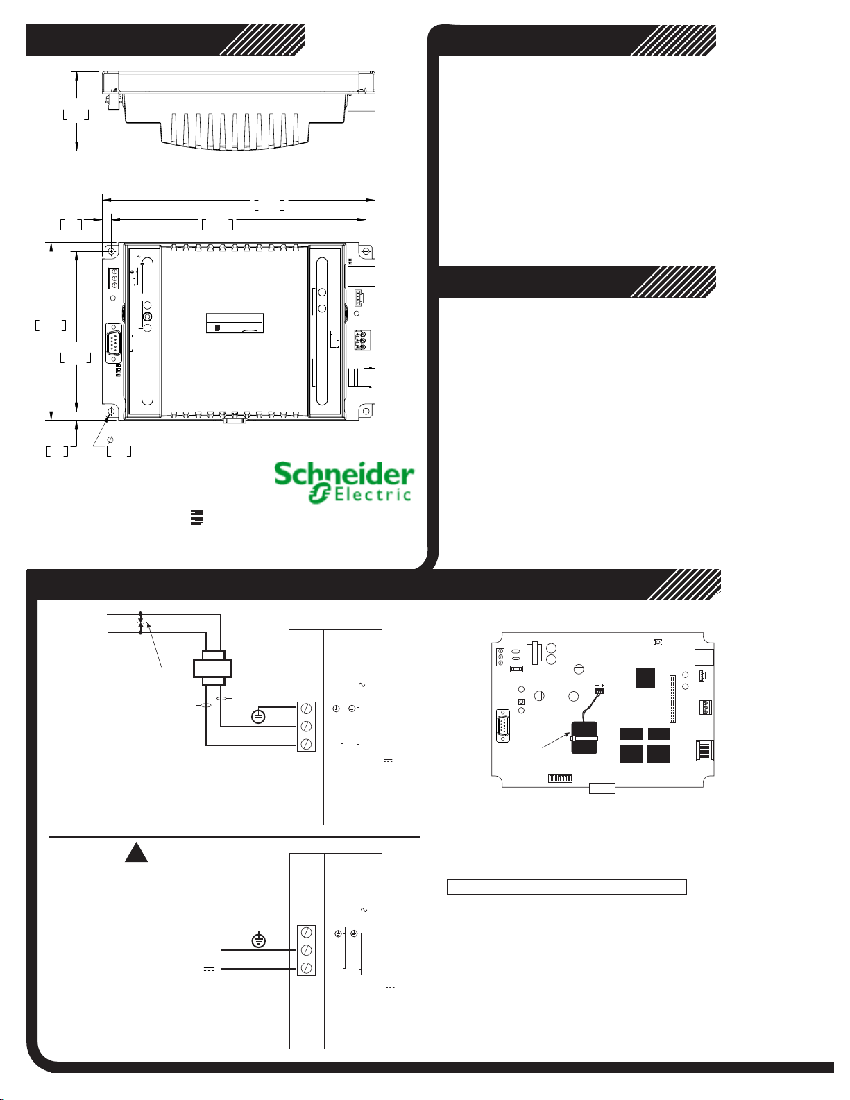
Mechanical
2.43
61.8
Wiring Rules
This controller is intended for installation within the enclosure
of another product
For reliable input operation, follow these input wiring guidelines:
· Never lay wires across the surface of a printed circuit board.
· Wires should never be within 1 in. or 25 mm of any component
on a printed circuit board.
.
8.39
213.2
LINK/ACT
10/100
Mbps
ETHERNET
10/100
BASE T
RD
SERVICE
PORT
TD
C
O
Series
b
b
CC
1
X
X
Series Installation
1
X
M
RS-485
M
SHLD
P
O
R
T
2
RS
232
5.47
138.9
.27
7.0
.27
7.0
4.92
125.0
.187
4.75
INPUT POWER
24 VAC
40 VA
50/60 HZ
12-28 VDC
N ( )
L ( )
RESTART
xP EXP
PORT
VDC
24
400mA
COMM
PORT 1
RS-232
(DTE)
DCD
RTS
RD
TD
25W
BACNET (GREEN)
INFINET (YELLOW)
CPU
b
7.85
199.3
C
30-3001-886 Rev D.1
DC Power & Battery Backup Connection
Grounding the Controller
To insure proper operation of the controller, it is imperative that it be connected
to a good Earth ground. It is important that this connection be made as close to
the module as possible.
Configuration
1. Disable DHCP, set the IP Address of your PC to 169.254.1.2
2. Connect a crossover cable from the Ethernet port to your PC
3. Run W
4. Logon using default Schneider Electric username and password
5. Enter parameters on Web screen
6. After entering parameters, click the Commit Changes/Restart
eb Browser, go to url: http://169.254.1.1
Controller button on the web screen.
AC Line
Power
Choose a voltage rating appropriate to
the input volt
Optional Varistor
age applied. i.e 130V or 250V
Black
X1
AC Connection
!
Use care when attaching power
wiring to these connectors.
They are not to be used as a strain relief.
The connectors cannot withst
excessive bending or flexing.
+ 12 to 28VDC
DC Connection
and
VDC Return
24 VAC Step-Down
Transformer
X2
White or
Green
AC POWER
24 VAC
40 VA
50/60 HZ
N
L-+
DC POWER
12 - 28 VDC
25 W
AC POWER
24 VAC
40 VA
50/60 HZ
N
L-+
DC POWER
12 - 28 VDC
25 W
Battery Connection
IP
PBRST
BATTERY
BATTERY ENABLE
During shipment, the internal battery pack has been disconnected to prevent it from
draining prior to installation.
to access the board, then plug the battery connector into the receptacle shown above.
BATTERY DISPOSAL/REPLACEMENT
Unit must be powered-down before replacing battery
Overcharging, short circuiting, reverse charging, mutilation or incineration of the cells
must be avoided to prevent one or more of the following occurrences; release of toxic
materials, release of hydrogen and/or oxygen gas, rise in surface temperature.
If a cell has leaked or vented, it should be replaced immediately using protective gloves.
Replace with Schneider Electric Battery Part Number: BCX1-BAT-KIT. A fully
discharged battery requires 33 hours to fully charge.
BATTERY VENTILATION
The cabinet in which the controller is mounted must provide adequate ventilation to allow
for escape of any accumulation of any released gasses under normal conditions.
To activate the battery, remove the top of the plastic case
Page 2
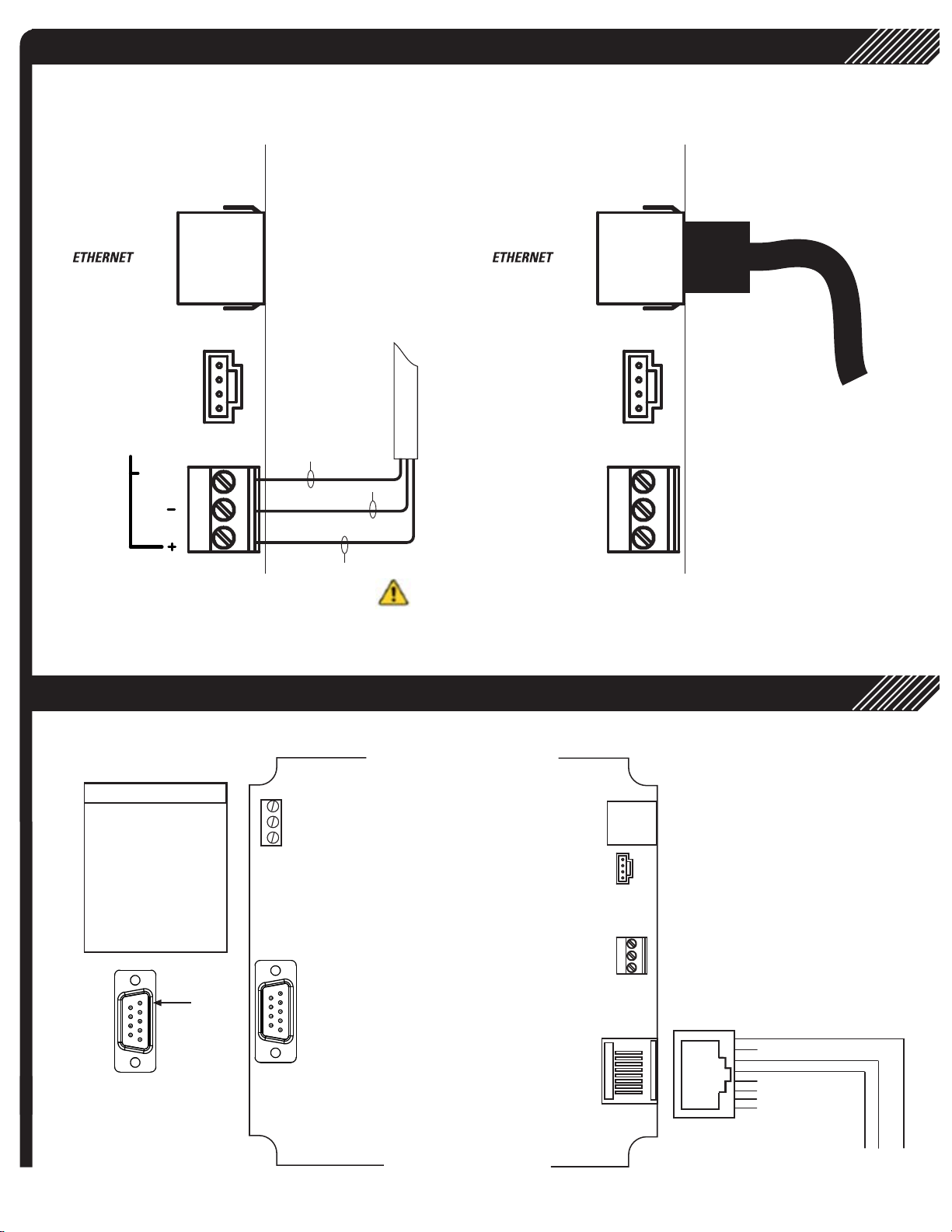
Field Bus Connection
ETHERNET Connection
Ethernet Cable w/
RJ-45 Connector
RS-485 Cable
RS-485
Shield
SHLD
RS232 COMM Connections
COMM 1
RS-232 Connector
PIN SIGNAL
1 DCD
2 RD
3 TD
4 DTR
5 Signal R
6 DSR
7 R
8 CTS
9 RI
TN
TS
White (+)
Black (-)
Warning: This product can expose you to chemicals including lead
which is known to the State of California to cause cancer and which is known
to the State of California to cause birth defects or other reproductive harm.
For more information, go to www.P65Warnings.ca.gov
COMM 2
RS-232 Connector
PIN 1
© 2019 Schneider Electric All Rights Reserved.
865
TD
RD
Ground
 Loading...