

Page 1
Application
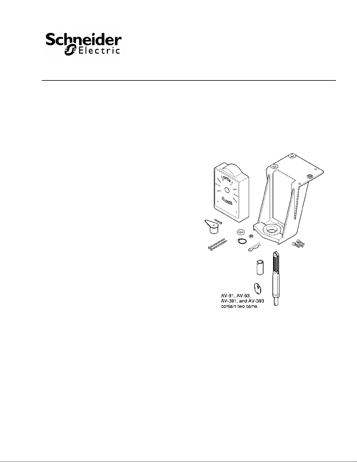
The AV-390 through AV-396 linkages are used to field assemble Schneider Electric gear train actuators to VB-7XXX series or VB-9XXX series valve bodies.
• AV-391 and AV-393 are used with cu rrent 1/2" to 2"
VB-7X1X and obsolete 1/2" to 1-1/4" VB-9X1X
valve
bodies.
• AV-392 and AV-394 are used with obsolete
1-1/2" and 2" VB-9X1X valve bodies.
• AV-395 and AV-396 are used with current 2-1/2" to
4" VB-9X1X valve bodies.
AV-390
Valve Linkage for
Gear Train Actuators
General Instructions
Features
• Die cast aluminum mounting bracket.
• Valve position indication provided as standard.
Applicable Literature
• Environmental Controls Cross-Reference Guide, F-
23638
• Environmental Controls Reference Manual,
F-21683
• Environmental Controls Application Manual,
F-21335
• Pneumatic Products Catalog, F-27383
• EN-205 Water System Guidelines, F-26080
Printed in U.S.A. 4/10 © Copyright 2010 Schneider Electric All Rights Reserved. F-24376-9
Page 2
SPECIFICATIONS
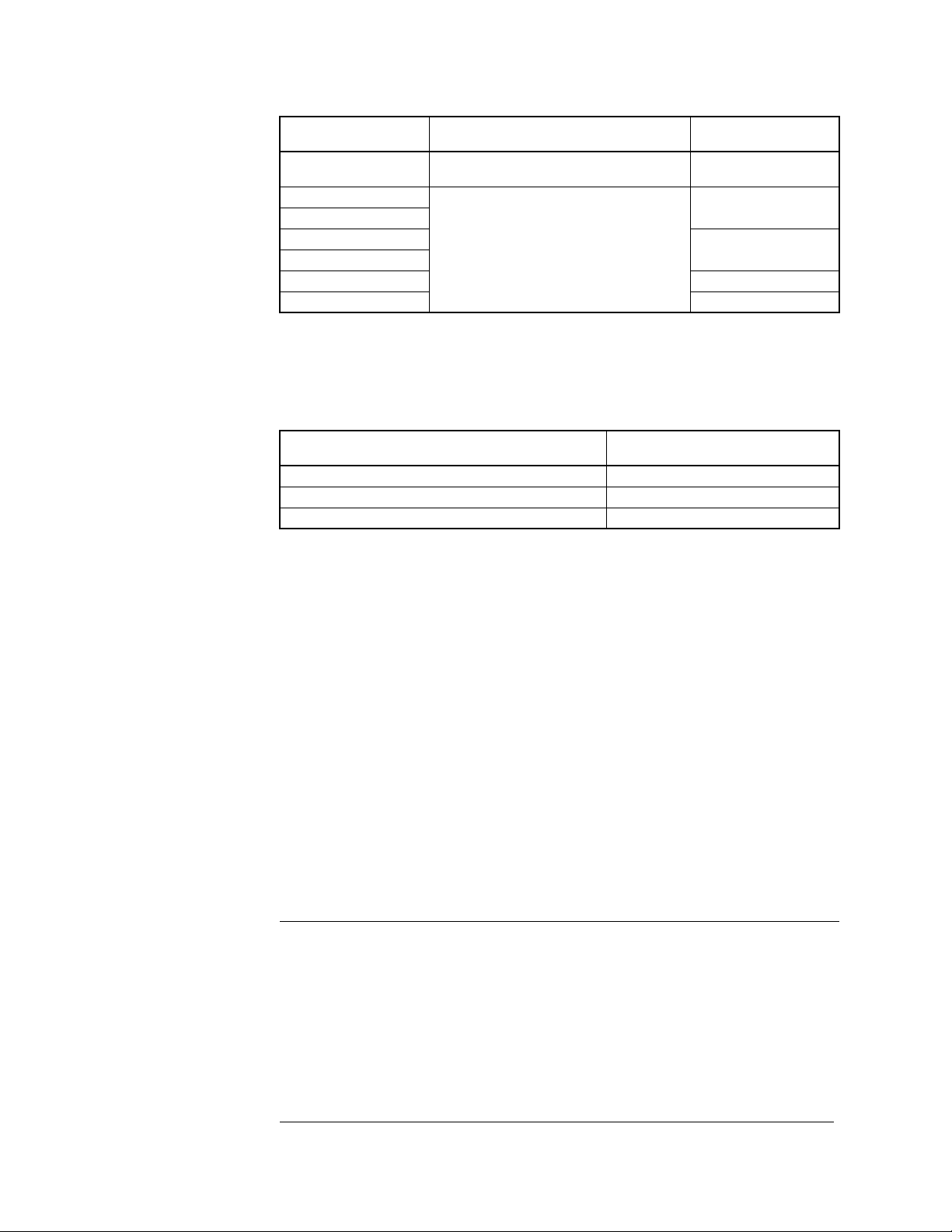
Table-1 Model Chart.
Valve Linkage
Model Number
AV-390
AV-391
AV-392
AV-393
AV-394
AV-395 150
AV-396 300
Cam, Plunger, and Stem Extension Kit
Req. AV-91, AV-92, AV-93, AV-94
Description
Complete Linkages
Stem Force
(lb.)
—
150
300
Temperature Restrictions
Verify that the fluid temperature of the media in the valve versus the ambient temperature at
the actuator does not exceed the ratings shown in
Table-2 Restrictions on Maximum Ambient Tem perature for Actuators.
Maximum Temperature of Media in the Valve
(Check Rating of Valve) °F (°C)
260 (126) 136 (57)
281 (138) 125 (52)
300 to 366 (149 to 185) 100 (37)
Table-1.
Maximum Ambient for Actuator
°F (°C)
Close-off Pressure Rating
Close-off pressure ratings are listed in Table-2 and Table-3. Check the appropriate table to
verify that the selected valve, valve linkage, and actuator provide adequate close-off
pressure for your application.
Required Components
The actuator, valve, and valve linkage should be purchased separately. See Table-2 and
Table-3 for selections.
INSTALLATION
Inspection Inspect the package for damage. If damaged, notify the appropriate carrier immediately.
If undamaged, open the package and inspect the device for obvious damage. Return
damaged products.
Requirements • Tools (not provided):
– Appropriate wrenches for stem extensions, lock nuts, packing nuts, and brackets
– Appropriate screwdriver for actuator mounting screws
– TOOL-37, 1-5/8" open-ended wrench with a maximum thickness of 3/16"
• Training: Installer must be a qualified, experienced technician
Caution:
• Avoid locations where excessive moisture, corrosive fumes, or vibration is present.
• Install all two-way valves so that they close against the flow. An arrow on the valve body
or a tag indicates the proper flow direction.
• Always install three-way mixing valves with two inlets and one outlet.
• Always install three-way diverting valves with one inlet and two outlets.
• The actuators can be mounted in any position above the centerline of the valve body.
For steam applications where the ambient temperature approaches the limit of the
actuator, the valve stem should be mounted 45° from vertical. When selecting a
location, allow sufficient room for accessories and for service of the product.
2 © Copyright 2010 Schneider Electric All Rights Reserved. F-24376-9
Page 3

Table-3 Linkage Selection and Valve Close-Off Pressure Ratings for VB-7XXX and VB-9X1X Valve Bodies.
TYPICAL ACTUATOR PART NUMBERS
VALVE BODY INFORMATION
Valve Body
Number
Part
VB-7211-0-3-P
VB-7211-0-4-P
VB-7213-0-4-P
VB-7214-0-4-P
VB-7215-0-4-P
VB-7253-0-4-P
VB-7273-0-4-P
VB-9213-0-4-P
VB-9215-0-4-P
VB-9213-0-5-P
VB-7313-0-4-P
VB-7314-0-4-P
VB-7315-0-4-P
VB-9313-0-4-P
VB-9315-0-4-P
VB-9313-0-5-P
a
kPa = psi x 6.895
Normally Closed
(Stem
MA-318, MA-318-500
MA-416, MA-416-500
MA-418, MA-418-500
MA-419, MA-419-500
Minimum Torque/Travel Required 50 lb.-in., 180° 100 lb.-in., 180°
Linkage for 1/2" to 2" Valves AV-391 (AV-390 & AV-91) AV-393 (AV-390 & AV-93)
Linkage for 2-1/2" to 4" Valves AV-395 AV-396
Description
2-Way
NPT
2-Way
NPT
2-Way
2-Way
125 lb.
Flanged
3-Way
3-Way
125 lb.
Flanged
P
Size Cv
Code
1
2 1.3
3 2.2
4 5.0
5
6 8.5
7
8 16
9 1-1/4" 22 90 200
1
2 1.3
3 2.2
4 4.4
5
6 7.5
7
8 14
9 1-1/4" 20 90 200
1
2 1.3
3 2.2
4 4.4
5
6 7.5
7
8 14
9 1-1/4" 20 90 200
10 1-1/2" 28 65 140
11 2" 40 35 80
12 2-1/2" 65 20 50
13 3" 85 12 34
12 2-1/2" 56 20 50
13 3" 85 12 34
14 4" 145 6 17
2
6 3/4" 7.5 220
8 1" 14 150 SU: 150 SD: 140
9 1-1/4" 20 100 SU: 100 SD: 95
10 1-1/2" 28 60 SU: 80 SD: 75
11 2" 41 33 SU: 200 SD: 190
12 2-1/2" 67 20 50
13 3" 91 12 34
12 2-1/2" 74 20 50
13 3" 101 12 34
14 4" 170 6 17
1/2"
3/4"
1"
1/2"
3/4"
1"
1/2"
3/4"
1"
1/2"
0.4
5.5
14
0.4
5.5
10
0.4
5.5
10
2.2
Down)
MP-361, MP-367
MP-461-600
MP-465, MP5-461
Normally Open
(Stem
MA-318, MA-318-500
MA-416, MA-416-500
MA-418, MA-418-500
MA-419, MA-419-500
MP-475, MP5-471
Up)
MP-371, MP-377
MP-471-600,
CLOSE-OFF PRESSURE (psi)
250
150
250
150
250
150
250
MP-421
MP-422
MP-2150-500
MP5-2151-500
No Normal Position
MC-351, MC-421, MC-431
MC-4211, MC-4311, MC5-4311
MP-381, MP5-381, MP-382
MP-387, MP-451, MP-452
MP-481-600
MP-485, MP-486
MP-4851, MP5-4851
a
250
250
250
250 4 4.4
F-24376-9 © Copyright 2010 Schneider Electric All Rights Reserved. 3
Page 4
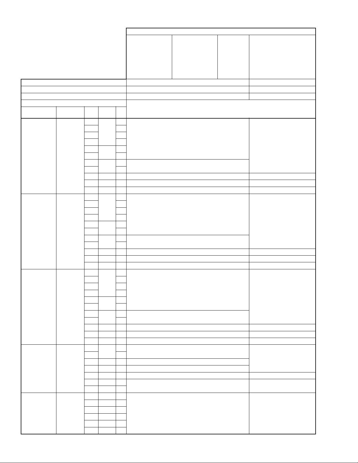
Table-4 Linkage Selection and Valve Close-off Pressure Ratings for Obsolete VB-9XXX Valve Bodies.
TYPICAL ACTUATOR PART NUMBERS
VALVE BODY INFORMATION
Valve Body
Part Number
VB-9213-0-4-P
VB-9253-0-4-P
VB-9273-0-4-P
VB-9313-0-4-P
VB-9323-0-4-P
a
kPa = psi x 6.895
Normally Closed
(Stem Down)
MA-318, MA-318-500
MA-416, MA-416-500
MA-418, MA-418-500
MA-419, MA-419-500
MP-361, MP-367
MP-461-600
MP-465, MP5-4651
Minimum Torque/Travel Required 50 lb.-in., 180° 100 lb.-in., 180°
Linkage for 1/2" to 1-1/4" Valves AV-391 (AV-390 & AV-91) AV-393 (AV-390 & AV-93)
Linkage for 1-1/2" & 2" Valves AV-392 (AV-390 & AV-92) AV-394 (AV-390 & AV-94)
Description
2-Way
FNPT
Composition
Disc
2-Way
FNPT
Stainless
Trim
Teflon Disc
2-Way
FNPT
Stainless
Trim
No Disc
3-Way
Mixing
FNPT
3-Way
Diverting
FNPT
P
Size Cv
Code
1
2 1.3
3 2.2
4 3.6
5
6 6.2
7
8 11
9 1-1/4" 16 90 200
10 1-1/2" 25 65 140
11 2" 40 35 80
1
2 1.3
3 2.2
4 3.6
5
6 6.2
7
8 11
9 1-1/4" 16 90 200
10 1-1/2" 25 65 140
11 2" 40 35 80
1
2 1.3
3 2.2
4 3.6
5
6 6.2
7
8 11
9 1-1/4" 16 90 200
10 1-1/2" 25 65 140
11 2" 40 35 80
2
4 4
6 3/4" 6.8 200
8 1" 12 140
9 1-1/4" 16 95 190
10 1-1/2" 33
11 2" 55
4 1/2" 6
6 3/4" 8
8 1" 12
9 1-1/4" 16
10 1-1/2" 30
11 2" 42
1/2"
3/4"
1"
1/2"
3/4"
1"
1/2"
3/4"
1"
1/2"
0.4
5
8.2
0.4
5
8.2
0.4
5
8.2
2
Normally Open
(Stem Up)
MA-318, MA-318-500
MA-416, MA-416-500
MA-418, MA-418-500
MA-419, MA-419-500
MP-371, MP-377
MP-471-600
MP-475, MP5-4751
CLOSE-OFF PRESSURE (psi)
250
150
250
150
250
150
250
33 75
250 250
No Normal
Position
MP-421
MP-422
MP-2150-500
MP5-2151-500
MC-351, MC-421, MC-431
MC-4211, MC-4311, MC5-4311,
MP-381, MP-382, MP-387
MP-445-304, MP-451, MP-452,
MP-481-600, MP-485, MP-486,
a
No Normal Position
MP-4851, MP5-4851
250
250
250
250
4 © Copyright 2010 Schneider Electric All Rights Reserved. F-24376-9
Page 5
ASSEMBLY PROCEDURE
The following bold italic headings are instructions for step one. Select the specific A V-3XX
instructions for the proper valve size. After the mounting bracket is attached, proceed to step
2. See page
Note: Position the bracket on the valve in such a way as to make it convenient to wire the
actuator.
8.
AV-391 or AV-393 Valve Linkage for 1/2" to 2" VB-7XXX
and Obsolete 1/2" to 1-1/4" VB-9XXX Valve Bodies
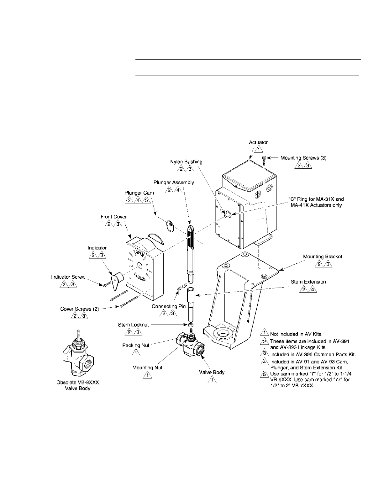
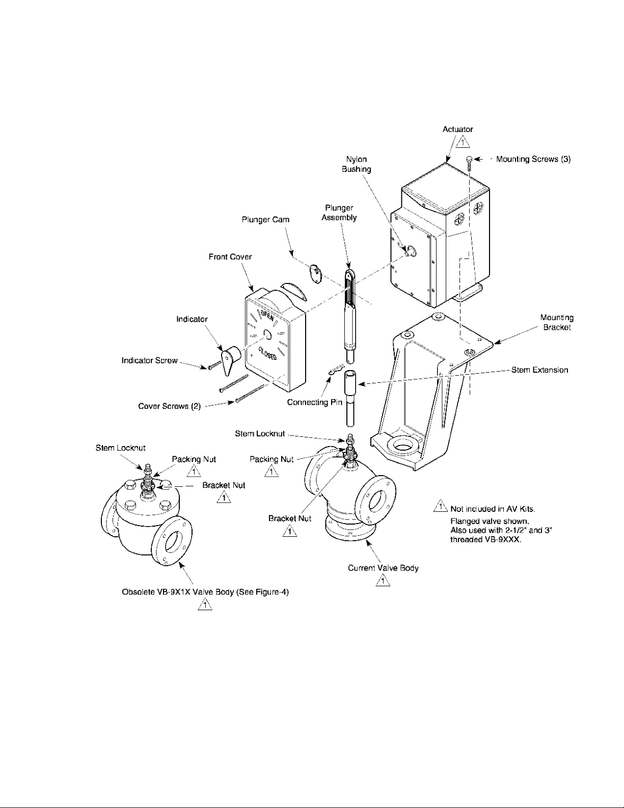
1. Mount the bracket on the valve body by screwing the mounting nut into the mounting bracket. Tighten the hex mounting nut, using a 1-5 /8" open-e nded wren ch with a maximum thickness of 3/16" (TOOL-37). See Figure-1.
Figure-1 Valve Linkages for 1/2" to 2" VB-7XXX and Obsolete 1/2" to 1-1/4" VB-9XXX Valve Bodies.
F-24376-9 © Copyright 2010 Schneider Electric All Rights Reserved. 5
Page 6

AV-392 or AV-394 Valve Linkage for Obsolete 1-1/2" to 2" VB-9XXX Valve Bodies
1. Mount the bracket onto the valve body as follows: a. For Style A VB-9XXX valve bodies, mount the bracket on the valve body by
screwing the mounting nut into the mounting bracket. Tighten the hex mounting nut,
using a 1-5/8" open-ended wrench with a maximum thickness of 3/16" (TOOL-37).
Figure-1.
See
b. For Style B VB-9XXX valve bodies, mount the bracket onto the valve body by
removing the bracket nut, placing the bracket on the valve body, and replacing and
tightening the valve bracket nut. See
Figure-2.
Figure-2 Valve Linkages for Obsolete 1-1/2" to 2" VB-9XXX Valve Bodies.
6 © Copyright 2010 Schneider Electric All Rights Reserved. F-24376-9
Page 7
AV-395 or AV-396 on Current 2-1/2" to 4" VB-9X1X Valve Bodies
1. Mount the bracket onto the valve body by removing the bracket nut, placing the bracket on the valve body, and replacing and tightening the valve bracket nut. See Fig ure -3.
Figure-3 Valve Linkages for Current 2-1/2" to 4" VB-9X1X Valve Bodies.
F-24376-9 © Copyright 2010 Schneider Electric All Rights Reserved. 7
Page 8

AV-395 or AV-396 on Obsolete 2-1/2" to 4" VB-9X13 Valve Bodies
If any of the old style packing
components (no longer
available) require replacement,
replace the entire assembly
with the current YBA-652. The
old style bonnet assembly can
easily be identified by noting the
large hex head packing gland
nut with internal threads.
See Figure-4 and YBA-651-1 & YBA-652, Valve Packing Kits General Instructions,
F-24185 for details.
Caution: Before the packing nut is removed, the system pressure on the valve must be
reduced to zero (0) psig. If the packing nut is removed while there is pressure on the valve,
the packing can blow out of the valve.
1. Mount the bracket onto the valve body as follows: a. Remove the packing nut and the bracket nut. b. Place the bracket onto the valve body. c. Replace and tighten the valve bracket nut. d. Replace the packing nut.
Figure-4 Valve Linkage for Obsolete 2-1/2" to 4" VB-9X13 Valve Bodies.
The following steps are common to all AV-390 valve linkages. Proceed with step 2 after
completing step 1 for the selected linkage.
2. Thread the stem lock nut and stem extension down fully onto the valve stem.
3. Place the actuator onto the mounting bracket. Fasten the actuator to the mounting bracket with the three 1/4 - 20 screws. Do not tighten the screws.
4. Place the nylon bushing onto the actuator shaft. (MA-31X and MA-41X actuators require that a “C” ring be installed into the groove on the actuator shaft before placing the nylon bushing onto the shaft.)
5. Position the actuator to the 3:00 (CW) or 9:00 (CCW) position so that the plunger cam
is pointing down. Use Figure-5 and Table-4Table-5 to determine whether the 3:00 (CW)
or 9:00 (CCW) position is the correct one for the plunger cam to be pointing down for
the application.
Figure-5 Actuator Shaft Position (Front View).
8 © Copyright 2010 Schneider Electric All Rights Reserved. F-24376-9
Page 9

Table-5 Actuator Shaft and Cam Position.
Cam Down
Cam Up
Cam Up
Cam Down
Actuator
Shaft
Position
CW
Short tooth on
actuator shaft
at 9:00
CCW
Short tooth on
actuator shaft
at 3:00
Standard Factory Positions of Cam
except for Normally Closed Valves
w/MA-3XX and MA-4XX Actuators
Optional Cam Position Used to Reverse
Control Action (Standard for Normally
Closed Valves w/MA-3XX and MA-4XX)
6. Place the plunger cam in the plunger and slip the plunger cam ont o the actuator shaft with the cam pointing down. Consult Table-6 for the proper cam.
Table-6 Cam Selection.
Use Cam
Marked
“7”
“77” 1/2" to 2" VB-7XXX
“44-2” AV-92, AV-392, AV-394, AV-395, AV-396
Included in Linkage Kits For These Valve Bodies
AV-91, AV-391, AV-93, AV-393
1/2" to 1-1/4" Obs. VB-9XXX
2-1/2" to 4" VB-9XXX
1-1/2" & 2" Obs. VB-9XXX
With
Nominal
Stroke
1/2"
1"
7. Push the valve stem completely down against the lower valve seat.
8. Screw the stem extension until the holes in the stem extension and plunge r line up.
9. Turn the stem extension upward, counterclockwise, into the plunger 2 full turns for 1/2" to 2" valves and 1-1/2 turns for 2-1/2" to 4" valve s.
10. Raise the actuator up until the connecting pin can be inserted through the holes in the plunger and stem extension.
1 1 . Tighten the actuator mounting screws.
12. Tighten the lock nut against the stem extension.
13. Place the front cover over the plunger assembly and fasten it to the actuator with two self-tapping screws.
14. Install the position indicator to the end of the actuator shaft, pointing to “Closed”.
F-24376-9 © Copyright 2010 Schneider Electric All Rights Reserved. 9
Page 10

CHECKOUT
1. Drive the actuator so that the valve stem is fully up. If the valve is a three-way, check for
plunger compression. See
2. Drive the actuator so that the valve stem is fully down. Check for plunger compression.
Figure-7.
See
Note: Check the plunger spring compression, refer to Figure-6 and Figure-7. The length of
the stem extension should be adjusted so that the valve disc seats before the actuator
reaches the end of the closing stroke. The balance of the actuator stroke is taken up in the
plunger spring compression, which should be approximately 1/16" (1.6 mm). This provides
pressure on the disc in the closed position(s) and also compensates for disc and seat wear.
On three-way valves, spring compression must be provided on both upper and lower seats.
Figure-6.
Figure-6 Valve Compression Stem Up.
Figure-7 Valve Compression Stem Down.
10 © Copyright 2010 Schneider Electric All Rights Reserved. F-24376-9
Page 11
MAINTENANCE
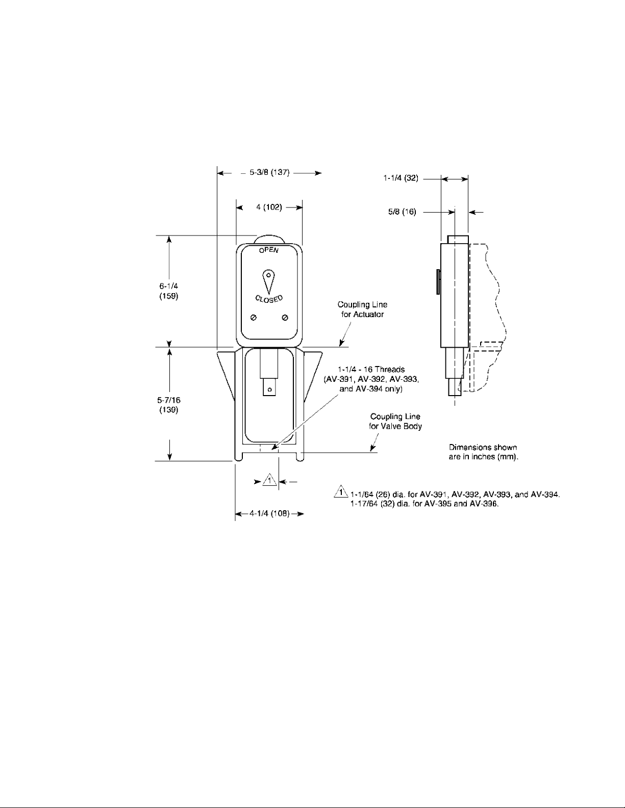
DIMENSIONAL DATA
Regular maintenance of the total system is recommended to assure sustained optimum
performance.
Figure-8 Dimensions of AV-391, AV-392, AV-393, AV-394, AV-395, and AV-396.
F-24376-9 © Copyright 2010 Schneider Electric All Rights Reserved. 11
Page 12

On October 1st, 2009 , TAC became the Buildings business of its parent compan y Sc hneider Electric. Thi s document reflects the visu al identit y of Schneider Electri c,
ho wever th ere remains referen ces to T AC as a co r porate br and in the body c opy. As each doc um ent i s updated, the body copy w ill be changed to r e flect appropri a te
corpo rate br a nd ch a nges.
Copyright 2010, Schneider Electric
All brand names, trademarks and registered
trademarks are the property of their respective
owners. Information contained within this
document is subject to change without notice.
F-24376-9
 Loading...