

Application
The AV-352 valve linkage is used to field-install gear
train actuators on specified 2-1/2" to 6" valve bodies.
Features
• Compatible with Schneider Electric
2-1/2" to 6" valves
AV-352
Gear Train Actuator Valve Linkage
General Instructions
• Provides increased close-off pressure on
2-1/2" to 4" valves
• Required for rated close-off pressure on
5" and 6" valves
Applicable Literature
• Environmental Controls Cross-Reference Guide,
F-
23638
• Environmental Controls Reference Manual,
F-
21683
• Environmental Controls Application Manual,
F-
21335
• Environmental Controls Catalog, F-16650
Printed in U.S.A. 6-10 © Copyright 2010 Schneider Electric All Rights Reserved. F-19070-7

SPECIFICATIONS Close-Off Pressure Rating
Refer to Table-1 and Table-2 to make sure the valve, valve linkage, and actuator are
compatible with each other, and that the close-off rating is adequate.
Table-1 Valve Close-Off Ratings, Pivot Pin Position, and Crank Arm Pivot Radius.
Valve Body Information
Valve Body
Part Number
VB-202-0-2-12
VB-202-0-2-13 85 3 77 (531) 1 2 (50.8)
VB-202-0-2-14 145 4 42 (290) 1 2 (50.8)
VB-202-0-2-15 235 5 20 (138) 2 2-1/2 (63.5)
VB-202-0-2-16 350 6 14 (97) 2 2-1/2 (63.5)
VB-804-0-2-12
VB-804-0-2-13 101 3 77 (531) 1 2 (50.8)
VB-804-0-2-14 170 4 42 (290) 1 2 (50.8)
VB-804-0-2-15 290 5 20 (138) 1 2-3/4 (69.8)
VB-804-0-2-16 390 6 14 (97) 2 2-1/8 (53.9)
VB-817-0-2-14
VB-817-0-2-15 "U" = 195, "L" = 220 5 125 (862) 1 2-1/2 (63.5)
VB-817-0-2-16 "U" = 250, "L" = 275 6 125 (862) 2 2-1/8 (53.9)
VB-9213-0-4-12 2-Way
VB-9213-0-4-13 85 3 77 (531) 1 2 (50.8)
Description C
2-Way
(Obsolete)
125 psig
Flanged
3-Way Mixing
(Obsolete)
125 psig
Flanged
3-Way Diverting
(Obsolete)
125 psig
Flanged
(Current)
250 psig
Screwed
"U" = 160, "L" = 180 4 125 (862) 1 2-1/4 (57.1)
v
56 2-1/2 112 (773) 1 2 (50.8)
74 2-1/2 112 (773) 1 2 (50.8)
56 2-1/2 112 (773) 1 2 (50.8)
Size
in.
Close-Off
Pressure*
psi (k Pa)
Pivot Pin
Position
Approximate
Crank Arm
Pivot Radius
in. (mm)
VB-9213-0-5-12
VB-9213-0-5-13 85 3 77 (531) 1 2 (50.8)
VB-9213-0-5-14 145 4 42 (290) 1 2 (50.8)
VB-9213-0-5-15 235 5 20 (138) 2 2-1/2 (63.5)
VB-9213-0-5-16 350 6 14 (97) 2 2-1/2 (63.5)
VB-9313-0-4-12 3-Way Mixing
VB-9313-0-4-13 101 3 77 (531) 1 2 (50.8)
VB-9313-0-5-12
VB-9313-0-5-13 101 3 77 (531) 1 2 (50.8)
VB-9313-0-5-14 170 4 42 (290) 1 2 (50.8)
VB-9313-0-5-15 290 5 20 (138) 2 2-1/2 (63.5)
VB-9313-0-5-16 390 6 14 (97) 2 2-1/2 (63.5)
VB-9323-0-5-14
VB-9323-0-5-15 "U" = 195, "L" = 220 5 125 (862) 1 2-1/2 (63.5)
VB-9323-0-5-16 "U" = 250, "L" = 275 6 125 (862) 2 2-1/8 (53.9)
*The actuator used must have a 180° travel and a minimum torque of 175 lb-in.
Typical Actuators: MC-351, MC-421, MC-431, MC-4311, MC5-4311, MP-381, MP-382, MP-451, MP-452,
MP-481-600, MP-485, MP-486, MP-4851, and MP5-4851
2-Way
(Current)
125 psig
Flanged
(Current)
250 psig
Screwed
3-Way Mixing
(Current)
125 psig
Flanged
3-Way Diverting
(Current)
125 psig
Flanged
56 2-1/2 112 (773) 1 2 (50.8)
74 2-1/2 112 (773) 1 2 (50.8)
74 2-1/2 112 (773) 1 2 (50.8)
"U" = 160, "L" = 180 4 125 (862) 1 2-1/4 (57.1)
2 © Copyright 2010 Schneider Electric All Rights Reserved. F-19070-7

Table-2 Pivot Pin Position and Crank Arm Pivot Radius
for Valves Not Included in Table-1.
Temperature Restrictions
Valve Stroke
(For Rated Flow)
Stem Up to
Stem Down
in. (mm)
1 (25.4) 1-1/16 (26.9) 1-1/8 (28.5) 1 2-1/8 (53.9) 2-1/4 (57.1) 0.252
1-1/8 (28.5) 1-3/16 (30.1) 1-1/4 (31.7) 1 2-3/8 (60.3) 2-1/2 (63.5) 0.252
1-1/4 (31.7) 1-5/16 (33.3) 1-3/8 (34.9) 1 2-5/8 (66.6) 2-3/4 (69.8) 0.252
1-3/8 (34.9) 1-7/16 (36.5) 1-1/2 (38.1) 1 2-7/8 (73) 3 (76.2) 0.252
1-1/2 (38.1) 1-9/16 (39.6) 1-5/8 (41.2) 2 2 (50.8) 2-1/8 (53.9) 0.385
1-3/4 (44.4) 1-13/16 (46) 1-7/8 (47.6) 2 2-3/8 (60.3) 2-1/2 (63.5) 0.385
2 (50.8) 2-1/16 (52.3) 2-1/8 (53.9) 2 2-5/8 (66.6) 2-3/4 (69.8) 0.385
2-1/4 (57.1) 2-5/16 (58.7) 2-3/8 (60.3) 2 3 (76.2) 3-3/32 (78.5) 0.385
For a 180° actuator: crank arm pivot radius = (required lift/2)(lever ratio).
Example: If the required lift is 1-1/8", the crank arm pivot radius = (1.125/2)(0. 252) = 2.232", or approximately 2- 1/4".
Required Linkage Lift
Including 1/16"
Compression on Valve Seats
in. (mm)
2-Way Valve 3-Way Valve 2-Way Valve 3-W ay Valve
Required
Pivot Pin
Position
Approximate Crank Arm
Pivot Radius
in. (mm)
Lever
Ratio
Verify that the fluid temperature of the media in the valve and the ambient temperature at
the actuator do not exceed the values shown in
Table-3.
Required Components
Table-3 Restrictions on the Maximum Ambient Temperature for the Actuators.
Maximum Temperature of Media in the Valve
(Check Ratings of Valve)
260°F (126°C) 136°F (57°C)
281°F (138°C) 125°F (52°C)
300°F (149°C) 100°F (37°C)
Maximum Ambient Temperature
for Actuator
The actuators and the valves (see Table-1 and Table-2) must be purchased separately.
F-19070-7 © Copyright 2010 Schneider Electric All Rights Reserved. 3

INSTALLATION
C A U T I O N
N O T E
W A R N I N G
Inspection
Requirements
Mounting
Inspect the package for damage. If damaged, notify the appropriate carrier immediately.
If undamaged, open the package and inspect the device for obvious damage.
Return damaged products.
• Tools (not provided):
– Appropriate wrenches for stem extensions, locknuts, packing nuts, and bracket nuts
– Appropriate screw driver for actuator mounting screws
• Training: Installer must be a qualified, experienced technician
1. Install all two-way valves so that they close against the flow. An arrow on the valve body or a tag indicates the proper flow direction.
2. Install all three-way mixing valves with two inlets and one outlet.
3. Install all three-way diverting valves with one inlet and two outlets.
4. Actuators can be mounted in any upright position above the centerline of a valve body.
5. When selecting a location, allow sufficient room for accessories and for service of the product.
Avoid locations where excessive moisture, corrosive fumes, or vibration is present.
ASSEMBLY PROCEDURE
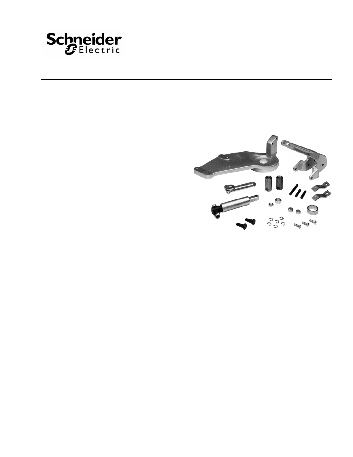
• Refer to Figure-1 during the assembly procedure for clarification, and for part s identification
and layout. The item designators used in Figure-1 are referenced in parentheses throughout the assembly procedure.
• Refer to Figure-3 for mounting dimensions of the linkage assembly.
1. If the packing nut must be removed from the valve, first isolate the valve body , using shutoff valves, or reduce the system pressure on the valve to zero (0) psig. Then, drain all the
fluid from the isolated or depressurized part of the system. Remove the packing nut from
the valve.
Reduce the system pressure in the valve to zero (0) psig and drain all the fluid from the i solated
or depressurized part of the system before removing the p acking nut. R emo ving the p acking
nut while pressure exsists in the valve may cause the packing part s to bl ow out of the valve,
causing bodily injury or water damage.
2. Remove the bracket nut from the valve body.
3. If the valve bonnet is 1" (25.4 mm) in diameter, place the bonnet collar around it.
4. Position the mounting base (D) onto the valve body and secure it in place with the bracket nut. Replace the packing nut if it was removed.
5. Install the actuator (A) onto the mounting base (D), using the actuator mounting
(B).
screws
6. Assemble the two stem links (G) to the main arm (E), using the stem link studs (N) and the stem link nuts (P).
7. Screw the stem locknut (L) and the stem extension (K) well down onto the valve stem.
8. Determine the correct pivot pin location and the approximate crank arm pivot radius.
Refer to
valves not listed in Table-1, refer to Table-2.
Table-1 for applications using Schneider Electric valves. For applications using
4 © Copyright 2010 Schneider Electric All Rights Reserved. F-19070-7

H
P
N
G
E
Enlarged View
A
C
D
E
F
Valve Stem
(Part of Valve Assembly)
Packing Nut and Bracket Nut
(Part of Valve Assembly)
Hidden from View by
Plunger Assembly in the
"Valve Closed" Position
Set Crank Arm at this
Position with Actuator at
Clockwise (180°) End
of Stroke
P
R
H
J
R
R
H
K
L
N
39°
Approx.
Crank Arm
Pivot Radius
1/16" Plunger
Compression
Pivot
Position "1"
3-7/8"
Approx.
Pivot
Position "2"
ABC DEF
GHJKLN
P
R
Act.
Act.
Mtg
Screw
Act.
Crank
Arm
Mtg
Base
Main
Arm
Plunger
Assy.
Stem
Link
Stem
Link
Pin
Main
Arm
Shaft
Stem
Exten.
Stem
Locknut
Stem
Link
Stud
Stem
Link
Nut
"E" Ring
ITEM DESCRIPTIONS
B
F-19070-7 © Copyright 2010 Schneider Electric All Rights Reserved. 5
Figure-1 AV-352 Valve Linkage Assembly.

9. Install the main arm (E) onto the mounting base (D) at the pivot position determined in
N O T E
Full CW Position
Full CCW Position
Short Tooth on
Actuator Shaft
at 9:00
Short Tooth on
Actuator Shaft
at 3:00
the previous step, using the main arm shaft (J) and two "E" rings (R). Make sure that
the innermost hole of the mounting base is used for pivot position "1" and the outermost
hole is used for pivot position "2".
10. Operate the actuator to the full clockwise position (the short tooth on the actuator shaft
is at the 9:00 position). See
Figure-2.
Figure-2 Actuator Shaft Position (Front View).
11. With the actuator at the full clockwise position, position the actuator crank arm (C) on the actuator output shaft at approximately 45°. Tap the actuator crank arm into place, and secure it with the locknut.
12. Install the plunger (F) onto the main arm (E), using the stem link pin (H) and two "E" rings (R).
13. Install the plunger (F) onto the actuator crank arm (C) at the pivot radius determined earlier.
14. With the valve stem fully down against the valve’s bottom seat, turn the stem extension (K) until the hole in the stem extension aligns with the holes in the stem links (G). Then turn the stem extension CCW (upward), one full turn.
15. Operate the actuator (A), as necessary, to realign the holes in the stem extension (K) and stem links (G). Insert the stem link pin (H) into the holes, and secure it in place with two "E" rings (R).
6 © Copyright 2010 Schneider Electric All Rights Reserved. F-19070-7
For MC actuators, remove the power from the actuator once the holes in the stem extension and stem links are realigned.
16. Adjust the plunger compression (see Figure-1) at the stem down position as follows: a. Operate the actuator (A) to its full clockwise position (the short tooth on the actuator
shaft is at the 9:00 position). See Figure-2. The valve stem should be fully down.
b. Check that the plunger compression is approximately 1/16" (1.6 mm).
c. If the plunger compression is less than required, increase it by turning the stem
extension (K) counterclockwise.
d. If the plunger compression is more than required, decrease it by turning the stem
extension (K) clockwise.

MAINTENANCE
9"
(228.6 mm)
12"
(304.8 mm)
1-17/64" (32.1 mm)
Diameter
FIELD REPAIR
17. If the valve is a th ree-way type , adjust the plunger compression at the stem up position as follows:
a. Operate the actuator (A) to its full counterclockwise position (the short tooth on
the actuator shaft is at the 3:00 position). See Figure-2. The valve stem should
be fully up.
b. Check that the plunger compression is approximately 1/16" (1.6 mm).
c. If the plunger compression is less than required, increase it by increasing the crank
arm pivot radius.
d. If the plunger compression is more than required, decrease it by decreasing the
crank arm pivot radius.
e. If the crank arm pivot radius is changed, the stem extension must be readjusted to
provide proper plunger compression on the valve’s bottom seat. If readjustment is
required, repeat the plunger compression adjustment procedure at the stem down
position. This will ensure proper plunger compression in both the stem up and stem
down positions.
18. When adjustment of the plunger compression is completed, tighten the stem locknut (L) against the stem extension (K) to secure the stem extension in position.
The actuator linkage requires no maintenance.
Regular maintenance of the total system is recommended to assure sustained, optimum
performance.
Individual parts of the actuator linkage are not repairable. Replace an inoperative actuator
linkage with a functional unit.
DIMENSIONAL DATA
Figure-3 Mounting Dimensions of Valve Linkage Assembly.
F-19070-7 © Copyright 2010 Schneider Electric All Rights Reserved. 7

On October 1s t, 2009, TA C became the Buildings business of its parent company Schneider Electric. This document r eflects the visual identity of Schneider Electric,
however there remains r eferences to TAC as a cor porate brand in the body copy. As each doc um ent is updated, the body copy wi ll be changed to r eflect appropriate
corporate brand changes.
Copyright 2010, Schneider Electric
All brand names, trademarks and registered
trademarks are the property of their respective
owners. Information contained within this
document is subject to change without notice.
F-19070-7
 Loading...