

Page 1
TAC Vista
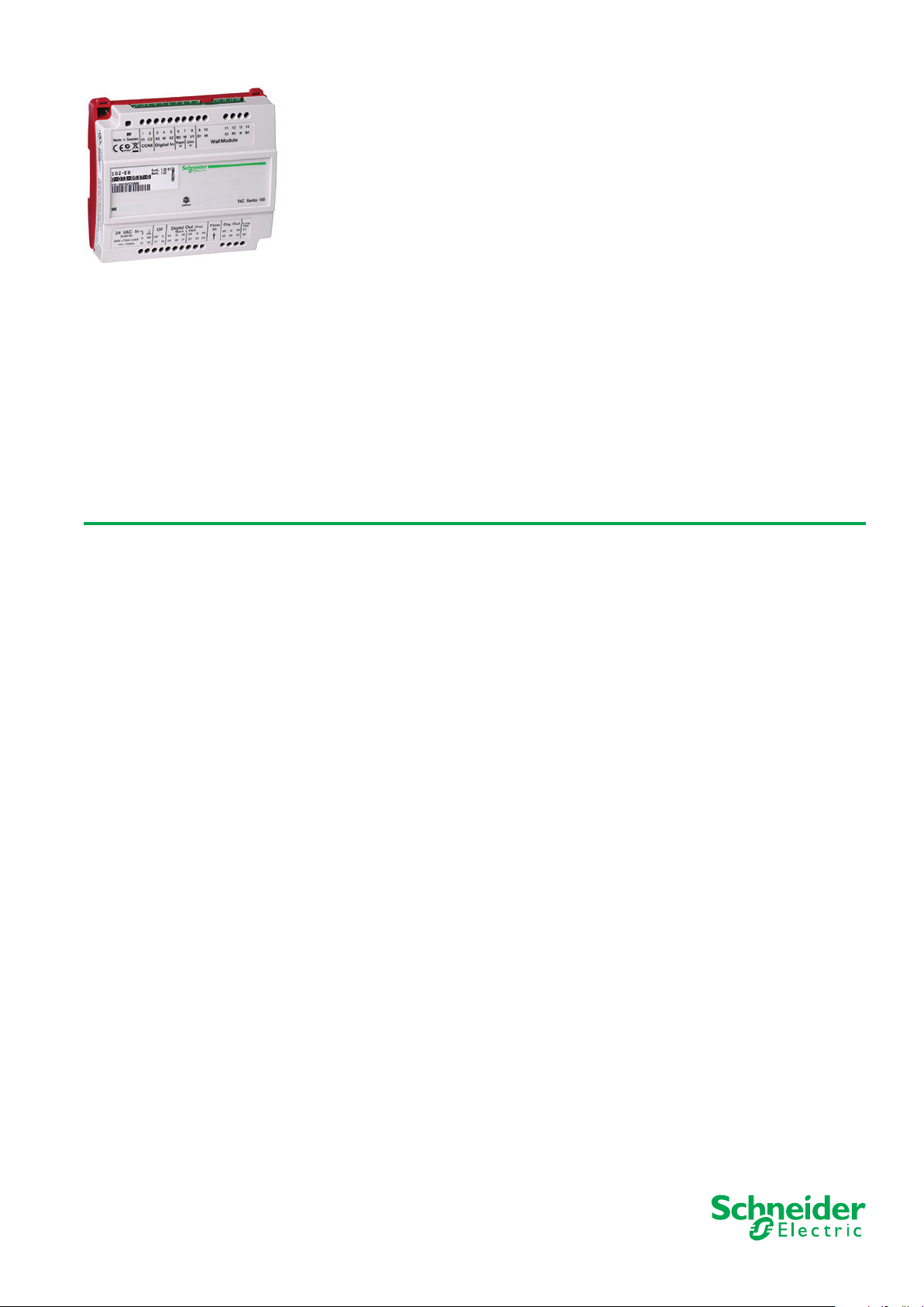
TAC Xenta® 102-VF
VAV Controller with Valve Reheat
TAC Xenta 102-VF is a zone controller for VAV heating and cooling applications that use fan on/off control and modulating valve
reheat.
The con trol ler keeps a constant temperature by controlling the air flow with the aid of a Belimo® VAV Compact; a valve reheat coil
is used for the hea t ing stage. Through a carbon dioxide sensor, the air quality can be controlled in the zone.
The controller is a LonMark compliant device that communicates on a LonTalk TP/FT-10 network via a twisted-pair, unpolarized
cable. It is able to operate both as a stand-alone unit and as part of a system. All network variables can be monitored and configured
via the TAC Xenta OP, if the OP version is 3.11 or higher.
STR 100 is a range of wall modules intended to be used together with TAC Xenta 102.
There are plug-in terminal blocks available for the TAC Xenta 100 series that can be attached to the existing terminals.
TECHNICAL DATA
Supply voltage............ 24 V AC –10% +20%, 50–60 Hz
Power consumption:
Controller with TAC Xenta OP ....................4 VA
Actuator supply ..........................max. 12 VA
Digital output............................max. 19 VA
Total...................................max. 35 VA
Ambient Temperature
Storage ................–20 °C to +50 °C (– 4 °F to 122 °F)
Operation ................0 °C to +50 °C (32 °F to 122 °F)
Humidity
Mechanical
Enclosure
Enclosure rating
Flammability class, materials
Dimensions
Weight
Inputs/Outputs
Inputs for occupancy sensor and window contact, X2–X3:
Output for fan on/off control, V1:
Maximum load................................0.8 A
Input for bypass button on wall module, X1:
Input for temperature sensor, B1:
Inputs for air flow and carbon dioxide sensor, Z1–Z2:
..................max. 90% RH non-condensing
....................................ABS/PC
.................................IP 30
...................UL 94 5VB
................................ see Fig. 1
...............................0.4 kg (0.88 lb.)
Voltage across open contact............23 V DC ±1 V DC
Current through closed contact ...................4 mA
Minimum pulse input duration X2/X3 .....250 ms / 15 sec.
Minimum output voltage ...........supply voltage – 1.5 V
Minimum pulse input duration .................. 250 ms
Maximum current, LED ...........2 mA, for ZS 100 series
Thermistor type ............NTC, 1800 W at 25 °C (77 °F)
Measuring range ........ –10 °C to 50 °C (14 °F to 122 °F)
Accuracy ..........................±0.2 °C (±0.36 °F)
Measuring range ......................... 0–10 V DC
Accuracy ..................................±0.05 V
Input setpoint adjustment on wall module, R1:
Type.......................10 kW linear potentiometer
Adjustment range........................±5 °C (±9 °F)
Accuracy ..........................±0.1 °C (±0.18 °F)
Outputs for air flow controller and reheat actuator, Y1–Y2:
Output range............................ 0–10 V DC
Maximum current .............................2 mA
Accuracy ...................................±0.2 V
Application Program
Cycle time ....................................15 sec.
Indication LED Colors
Power On .....................................green
..........................................red
Service
LonMark Standard
................... LonMark Interoperability Guidelines
..............LonMark Functional Profile: VAV Controller
Communication protocol
Physical channel
Neuron type
Agency Compliances
Emission:
CE ..................EN 61000-6-3, C-Tick, FCC Part 15
Immunity:
CE ..................................EN 61000-6-1
Safety
CE ....................................EN 61010-1
UL 916, C-UL US, Open Energy Management Equipment
Approved for plenum installations
RoHS directive............................ 2002/95/EG
Part Numbers
Controller ................................007305350
..................................0-004-7516
Manual
Plug-in Terminal Blocks TAC Xenta 100
......................TP/FT-10, 78 kbps
............................3150, 10 MHz
........................LonTalk
..........007309140
03-00130-02-en
Page 2
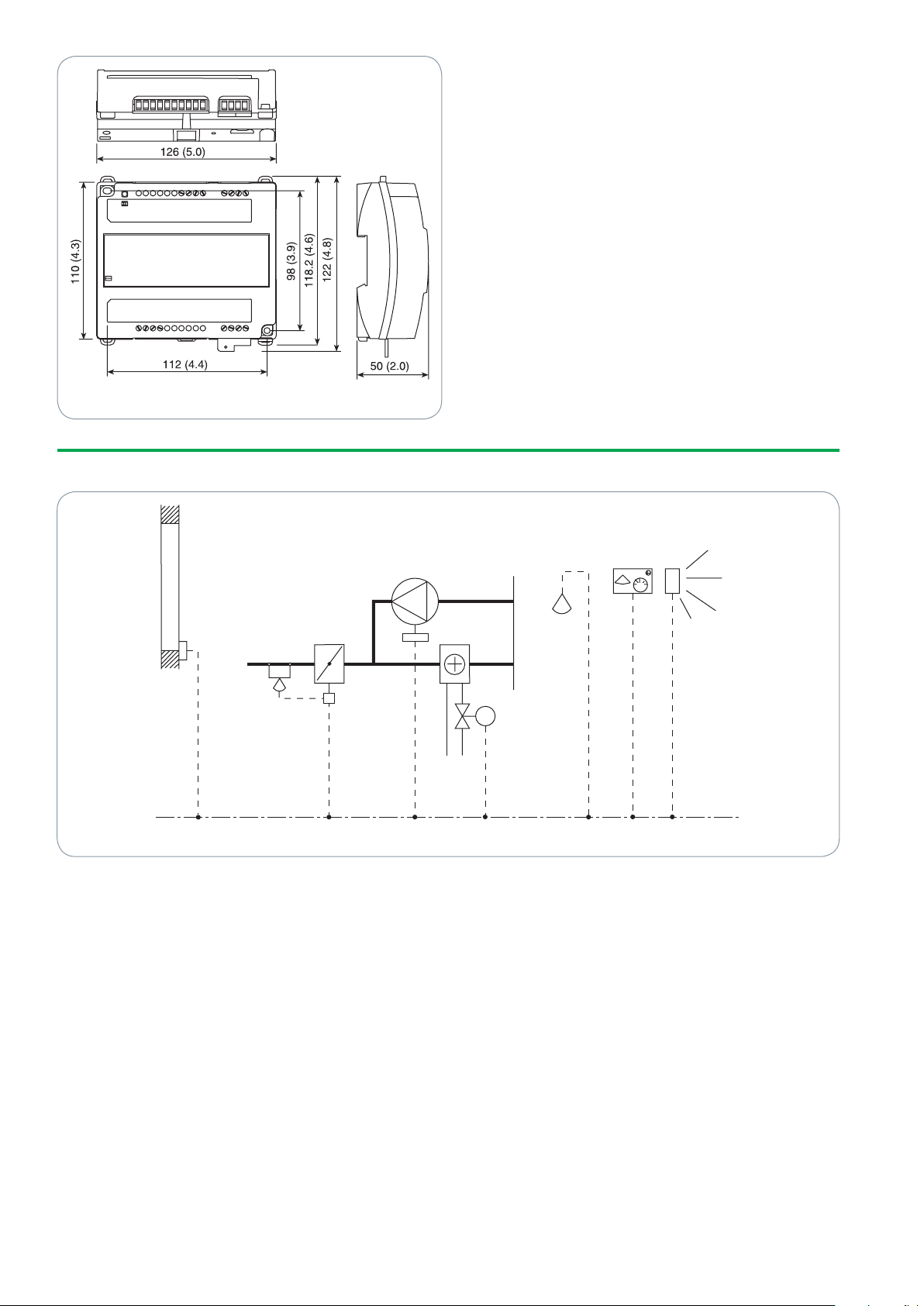
Figure 1
Window
contact
Fan
Damper and
air flow sensor
Valve reheat
Carbon
dioxide
sensor
Wall
module
Occupancy
sensor
2
03-00130-02-en
APPLICATION EXAMPLE
Figure 2
Page 3

0%
100%
HeatingCooling HeatingCooling
Neutral
zone
Neutral
zone
Cooling demandCooling demand
Fan disabled Fan enabled
0%
100%
100%
0%
Air flow
min
max
“low” limit“high” limit
CO
2
level
(ppm)
MAIN FUNCTIONS
3
03-00130-02-en
The function of TAC Xenta 102-VF is
determined by the occupancy mode, the
application mode, the emergency mode,
the manual mode and the node state.
The airflow and a valve reheat coil are
controlled to maintain the zone temperature in sequence. The airflow in crea ses
when the cooling demand in crea ses. If
the cooling demand in the zone decreases, the valve reheat is started, and the fan
runs (if a fan is enabled). Furthermore,
the airflow is set to its minimum value
with a fan, and the minimum heat value
without a fan.
Air Quality Control
In order to maintain the air quality, the
controller selects the highest of three possible air flow values: the air flow or dered
from the cooling sequence, the air quality
control or the set minimum air flow.
When carbon dioxide con centration is
high, the airflow is set from the air quality
control (see fig. 3); at other times, it is
set by the temperature con trol sequence.
The air quality control is enabled in the
occupied and bypass modes.
Figure 3
Figure 4
OPERATING MODES
Occupied Mode
Occupied mode is used when the zone
is occupied. This mode is also the de fault
mode after a reset or a power up. The fan
is on if it is enabled and the heating stage
is active.
Standby Mode
The standby mode is enabled. The neutral
In slave mode, both the slave and mas ter
controllers must be equipped with identical actuators and valves.
Night Purge Mode
In night purge mode, the air flow is set
to its maximum value in order to cool the
zone with outdoor air. If the controller is
used in a heating app lication, the heating
is off.
zone is larger than in occupied mode, and
the air flow is diminished from “minimum
occupied air flow” to “minimum standby
air flow”.
Bypass Mode
To bypass the centrally set standby mode,
press the by pass button on the wall module. The controller switches to oc cupied
mode. When two hours have passed, the
controller reverts to standby mode.
Unoccupied Mode
This mode is used when the building is
EMERGENCY MODE
Emergency mode is forced and has two
different settings:
• Shutdownmode–Thedamperisfully
closed.
• Purgemode–Theairflowissettoits
nominal value, which equals a fully
open damper.
When emergency mode is not needed,
the network variable is set to normal
control.
unoccupied for a longer pe riod. In this
mode, the neutral zone is even larger
than that of the standby mode. The fan is
con trolled in standby mode.
Off Mode
The controller stops running when off
mode is centrally ordered, when a window is opened or slave mode is enab led
in the controller.
Slave Mode
When the network variable nciAppOptions is set so that slave mode is enab led,
the following happens:
The slave controller goes into off mode
and receives copies of output signals from
the master controller.
INSTALLATION
The controller may be mounted on a DIN
rail or fastened onto a ceiling or a wall.
Two sockets are included to allow for this
type of installation.
CABLES
Communication cables: refer to the TAC
Xenta Network Guide, part number
0-004-7460.
Other cables: maximum length 30 m
(100 ft), minimum wire size of 0.7 mm²
(18 AWG) applies to all other cables and
all other equipment. The cables are to be
twisted, but not shielded.
CONFIGURATIONS OPTIONS
By changing the network variable nciAppOptions (see figure 6), it is possible
to achieve different options in TAC Xen ta
102-EF.
The factory setting of the controller is
that all auxi liary units are disabled. Below
is a list of the different options:
• Occupancysensorenabled/disabled
• Windowcontactenabled/disabled
• Fanenabled/disabled
• Airqualitycontrollerenabled/disabled
• Slavemodeenabled/disabled
• Occupancysensornormallyopen/nor-
mally closed
Page 4

Figure 5: LonMark Objects and Network Variables
4
03-00130-02-en
Page 5

HARDWARE INTERFACE
5
03-00130-02-en
Term.
No.
Term.
Name
Description
1 C1 TP/FT-10 communication channel
2 C2 TP/FT-10 communication channel
3 X3 Input, window contact
4 M Measurement neutral
5 X2 Input, occupancy sensor
6 Z2 Input, carbon dioxide sensor
7 M Measurement neutral
8 Z1 Input, air flow
9 D1 Output, indication on wall module
10 M Measurement neutral
11 X1 Input, bypass button on wall module
12 R1 Input, setpoint offset dial on wall module
13 M Measurement neutral
14 B1 Input, temperature sensor
15 G 24 V AC (G) input
16 G0 24 V AC (G0) input
17 OP 24 V AC supply for TAC Xenta OP
18 G 24 V AC supply for TAC Xenta OP
19 V1 Fan on-off control
20 G 24 V AC (G) output
21 G0 24 V AC (G0) output
22 Y2 Reheat valve actuator
23 M Measurement neutral
24 Y1 Air flow controller setpoint
25 – Not used
26 – Not used
27 – Not used
28 – Not used
ROOM UNITS
The STR is a series of wall modules optimized for public facilities such as office buildings, hotels, hospitals, schools, and shopping malls.
The following room units can be configured with the TAC Xenta 102-VF.
Model Temp.
Sensor
Mode
Indicator
Setpoint
Offset
Bypass
Button
Back
Light
SNVT
Binding
Required
STR100 X
STR101 X X
STR102 X X X
STR103 X X X
STR104 X X X X
STR350 X X X X X
STR351 X X X X X X
PART NUMBERS
STR100 .................004600100
STR100-W (White) ........004600110
STR101 .................004600200
STR102 .................004600300
STR103 .................004600700
STR104 .................004600400
LON Modules
STR350 .................004605000
STR351 .................004605100
Page 6

Copyright © 2008-2010, Schneider Electric
All brand names, trademarks and registered trademarks are
the property of their respective owners. Information contained
within this document is subject to change
without notice. All rights reserved.
03-00130-02-en Mar 2010
 Loading...