

Page 1
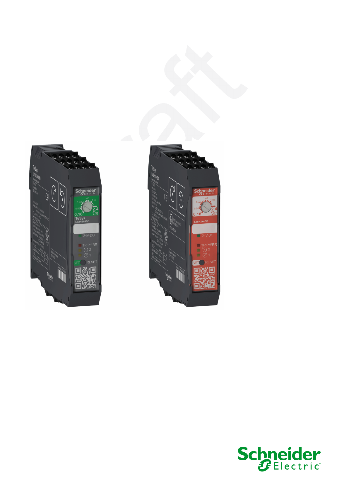
TeSys
TeSys Control - Hybrid Motor Starter
User Guide
TeSys offers innovative and connected solutions for motor starters.
DOCA0111EN-03
06/2025
www.se.com
Page 2

Legal Information
The information provided in this document contains general descriptions, technical
characteristics and/or recommendations related to products/solutions.
This document is not intended as a substitute for a detailed study or operational and
site-specific development or schematic plan. It is not to be used for determining
suitability or reliability of the products/solutions for specific user applications. It is the
duty of any such user to perform or have any professional expert of its choice
(integrator, specifier or the like) perform the appropriate and comprehensive risk
analysis, evaluation and testing of the products/solutions with respect to the relevant
specific application or use thereof.
The Schneider Electric brand and any trademarks of Schneider Electric SE and its
subsidiaries referred to in this document are the property of Schneider Electric SE or
its subsidiaries. All other brands may be trademarks of their respective owner.
This document and its content are protected under applicable copyright laws and
provided for informative use only. No part of this document may be reproduced or
transmitted in any form or by any means (electronic, mechanical, photocopying,
recording, or otherwise), for any purpose, without the prior written permission of
Schneider Electric.
Schneider Electric does not grant any right or license for commercial use of the
document or its content, except for a non-exclusive and personal license to consult it
on an "as is" basis.
Schneider Electric reserves the right to make changes or updates with respect to or in
the content of this document or the format thereof, at any time without notice.
To the extent permitted by applicable law, no responsibility or liability is
assumed by Schneider Electric and its subsidiaries for any errors or omissions
in the informational content of this document, as well as any non-intended use
or misuse of the content thereof.
Page 3

Table of Contents
Safety Information.......................................................................................5
About the Document...................................................................................6
Presentation.................................................................................................8
Introduction................................................................................................8
Hardware Description ............................................................................... 10
Protection Functions ................................................................................. 11
Motor Control Applications ...................................................................... 13
Motor Control Using a Standard TeSys H Motor Starter ............................... 13
Recommended Circuits for Motor Control in Safety Chain Applications
Using an STO TeSys H Motor Starter .........................................................14
Additional Circuits for Motor Control in Safety Chain Applications Using
an STO TeSys H Motor Starter................................................................... 21
Motor Control Using a Standard or STO Motor Starter for Motors with
Brake....................................................................................................... 24
Operation ...................................................................................................26
Commissioning ........................................................................................ 26
Diagnostic Functions ................................................................................ 29
Resetting the TeSys H Motor Starter .......................................................... 32
Protecting the Environment .......................................................................34
TeSys Control - Hybrid Motor Starter
Appendices ................................................................................................35
Combining the TeSys H Motor Starter with Circuit Breakers .........................35
Combining the TeSys H Motor Starter with Fuses........................................ 38
Technical Data ......................................................................................... 39
Safety Functions.......................................................................................42
Tripping Characteristics ............................................................................43
Derating Characteristics............................................................................ 44
Maximum Operating Rate for AC53A Duty.................................................. 47
DOCA0111EN-03 3
Page 4

Page 5

The addition of this symbol to a “Danger” or “Warning” safety label indicates that an
electrical hazard exists which will result in personal injury if the instructions are not
followed.
This is the safety alert symbol. It is used to alert you to potential personal injury
hazards. Obey all safety messages that follow this symbol to avoid possible injury or
death.
DANGER indicates a hazardous situation which, if not avoided, will result in death or serious
injury.
!
DANGER
WARNING indicates a hazardous situation which, if not avoided, could result in death or
serious injury.
WARNING
!
CAUTION indicates a hazardous situation which, if not avoided, could result in minor or
moderate injury.
CAUTION
!
NOTICE is used to address practices not related to physical injury.
NOTICE
Safety Information TeSys Control - Hybrid Motor Starter
Safety Information
Important Information
Read these instructions carefully, and look at the equipment to become familiar
with the device before trying to install, operate, service, or maintain it. The
following special messages may appear throughout this documentation or on the
equipment to warn of potential hazards or to call attention to information that
clarifies or simplifies a procedure.
Please Note
Electrical equipment should be installed, operated, serviced, and maintained only
by qualified personnel. No responsibility is assumed by Schneider Electric for any
consequences arising out of the use of this material.
A qualified person is one who has skills and knowledge related to the construction
and operation of electrical equipment and its installation, and has received safety
training to recognize and avoid the hazards involved.
DOCA0111EN-03 5
Page 6
TeSys Control - Hybrid Motor Starter About the Document
About the Document
Document Scope
This document describes the control functions of the TeSys™Hybrid motor starter.
This document is intended for the following users:
• Design engineers
• System integrators
• System operators
• Maintenance engineers
Validity Note
This guide is valid for all TeSys H motor starters.
The term TeSys H motor starter in this guide is used as the abbreviated name of
the TeSys Control - Hybrid motor starter.
Online Information
The characteristics of the products described in this document are intended to
match the characteristics that are available on www.se.com. As part of our
corporate strategy for constant improvement, we may revise the content over time
to enhance clarity and accuracy. If you see a difference between the
characteristics in this document and the characteristics on www.se.com, consider
www.se.com to contain the latest information.
Product Related Information
HAZARD OF ELECTRIC SHOCK, EXPLOSION, OR ARC FLASH
To prevent short circuit between primary and secondary sides:
• Disconnect all power before servicing equipment.
• Only use power supply units with safe isolation and PELV, according to EN
50178/VDE 0160 (PELV).
Failure to follow these instructions will result in death or serious injury.
DANGER
Environmental Data
For product compliance and environmental information, refer to the Schneider
Electric Environmental Data Program.
6 DOCA0111EN-03
Page 7

About the Document TeSys Control - Hybrid Motor Starter
Related Documents
Title of documentation Reference number
TeSys H - Instruction Sheet NHA6215000
You can download these technical publications and other technical information
from our website at www.se.com/ww/en/download/.
Information on Non-Inclusive or Insensitive Terminology
As a responsible, inclusive company, Schneider Electric is constantly updating its
communications and products that contain non-inclusive or insensitive
terminology. However, despite these efforts, our content may still contain terms
that are deemed inappropriate by some customers.
Trademarks
QR Code is a registered trademark of DENSO WAVE INCORPORATED in Japan
and other countries.
DOCA0111EN-03 7
Page 8
TeSys Control - Hybrid Motor Starter Presentation
Presentation
Introduction
TeSys Master Range
TeSys is an innovative motor control and management solution from the global
market leader. TeSys offers connected, efficient products and solutions for
switching and protection of motors and electrical loads in compliance with all
major global electrical standards.
Presentation of the TeSys H Motor Starter
At only 22.5 mm wide, the TeSys H is an ultra-compact motor starter.
Using hybrid technology that combines electromechanical relays, power solidstate components, and a solid-state overload function, the TeSys H motor starter
controls and protects three-phase motors up to 3 kW/500 V or resistive loads up to
9 A/500 V.
NOTICE
FALSE-TRIP HAZARD ON NON-SINUSOIDAL THREE-PHASE VOLTAGES
Do not use the TeSys H motor starter on the power side or load side of a
variable speed drive or soft starter.
Failure to follow this instruction can result in false trip.
NOTICE
FALSE-TRIP HAZARD ON SINGLE-PHASE VOLTAGE
Do not use the TeSys H motor starter to control and protect single-phase loads.
Failure to follow this instruction can result in false trip.
Product Range
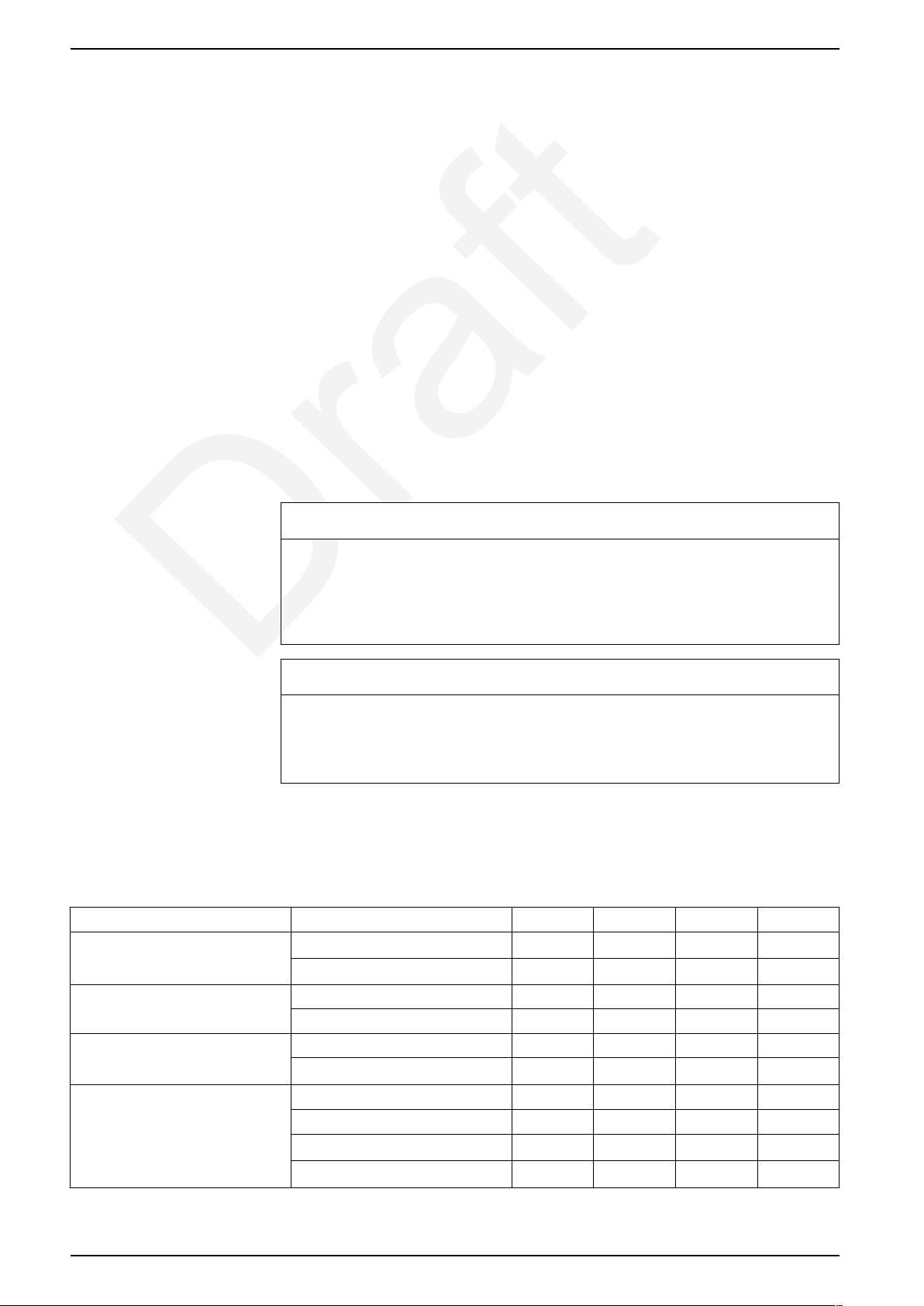
The following table shows the features available in the product range.
Feature Value LZ1H LZ2H LZ7H LZ8H
IEC rating 2.4 A/AC53A, 2.4 A/AC51
6.5 A/AC53A, 9 A/AC51
Control voltage 24 Vdc
110 V–230 Vac
Type of terminal Screw
Spring
Functions One direction
Two directions
Overload protection
Safe Torque Off (STO)
x x x x
x x x x
x x x x
x x x x
x x x x
x x x x
x – x –
– x – x
x x x x
– – x x
8 DOCA0111EN-03
Page 9

Presentation TeSys Control - Hybrid Motor Starter
Motor Control
The TeSys H motor starter is used to switch on and switch off three-phase,
asynchronous electrical motors used in single-direction or dual-direction
applications. The TeSys H motor starter protects the motors against overheating.
For dual-direction applications, leave a switching time of at least 180 ms when
switching between direction 1 (forward) and direction 2 (reverse).
Safe Torque Off (STO)
STO TeSys H motor starters LZ7H and LZ8H are designed for use in safety chain
applications.
Safety shutdown can be achieved to the following standards:
• SIL3 according to IEC61508-1
• PLe according to ISO13849-1
TeSys H motor starters LZ7H and LZ8H are ATEX certified as associated
components for motor protection.
DOCA0111EN-03 9
Page 10
TeSys Control - Hybrid Motor Starter Presentation
Hardware Description
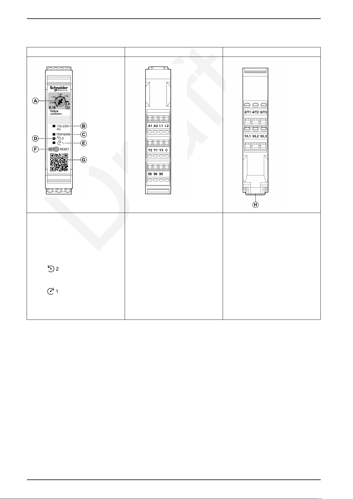
Product face Control terminals Power terminals
A: Potentiometer to adjust nominal current:
• 0.18 to 2.4 for 2.4 A devices
• 1.5 to 9 for 6.5 A devices
B: Auxiliary power supply LED (green), 24
Vdc or 110-230 Vac
C: TRIP/ERR trip or internal error LED (red)
D: LED
LZ2H and LZ8H only.
E: LED
F: SET/RESET button: Set/manual reset
G: Product information QR code
input I.2 status (yellow). On
input I.1 status (yellow)
A1, A2: Auxiliary power supply
I1: Control input, direction 1
I2: Control input, direction 2. On LZ2H and
LZ8H only.
Y1: Common point for reset mode
Y2: Remote reset mode
Y3: Automatic reset mode
C: Common point for control inputs. On
LZ7H and LZ8H only.
98, 96, 95: Trip and error signaling contact
2/T1, 4/T2, 6/T3: Motor connection
1/L1, 3/L2, 5/L3: Power inputs
H: Lock for fixing on DIN rail
10 DOCA0111EN-03
Page 11
Presentation TeSys Control - Hybrid Motor Starter
Protection Functions
Thermal Overload
The TeSys H motor starter protects three-phase motors against overload. If the
current exceeds the set value, the motor starter switches off within the specified
tripping time and indicates the cause of the trip through the TRIP/ERR LED and
the trip and error signaling contact.
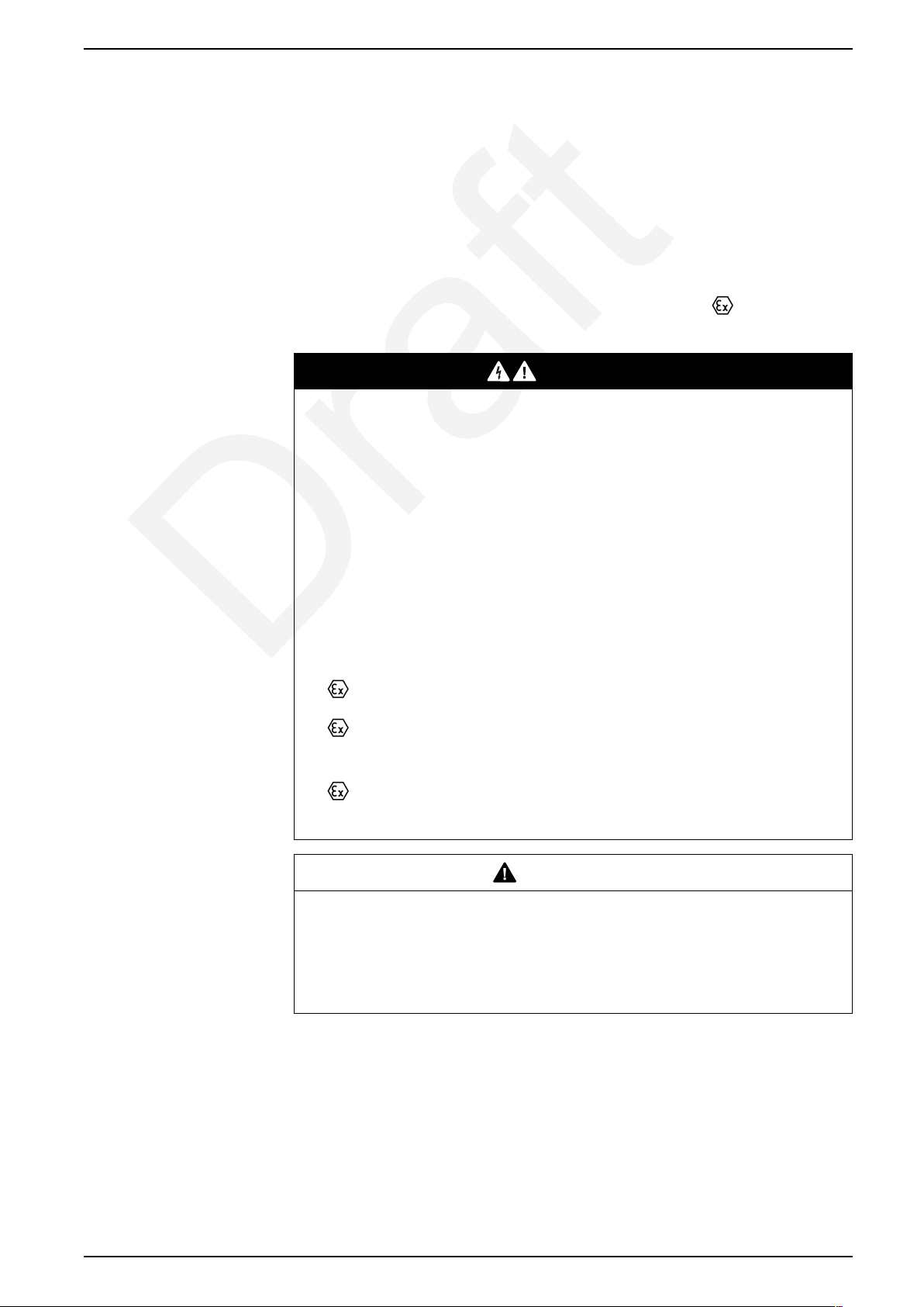
NOTE: Overload protection of LZ7H and LZ8H STO starters is ATEX-certified
up to SIL 2.
NOTE: Only LZ7H and LZ8H motor starters that bear the
left can be used to protect motors in an explosive atmosphere.
marking on the
DANGER
HAZARD OF EXPLOSION IN EXPLOSIVE ATMOSPHERE
The device is associated equipment and must not be installed in potentially
explosive areas. When installing and operating associated equipment, the
applicable safety directives must be observed.
• Observe the safety regulations that are applicable when motors are used in
the Ex area (ATEX directive 94/9/EC).
• In circuits in potentially dust-explosive areas of zones 21 and 22, it must be
guaranteed that the equipment connected to this circuit complies with
category 2D or 3D or is certified as such.
• For safety technical data, refer to this document and certificates (EC-type
examination certificate, and other approvals if appropriate).
Conformance/approvals:
• EC type-examination certificate
•
•
• PTB certification: refer to file number on product nameplate
II (2) G [Ex e] [Ex d] [Ex px]
II (2) D [Ex t] [Ex p]
Phase Unbalance
•
Failure to follow these instructions will result in death or serious injury.
marked devices only
WARNING
HAZARD OF INADEQUATE MOTOR PROTECTION
The current setting of the TeSys H motor starter must be adapted in accordance
with the motor to be protected.
Failure to follow these instructions can result in death, serious injury, or
equipment damage.
The TeSys H motor starter protects three-phase motors against phase unbalance.
• If motor currents differ from each other by more than 33%, the motor starter
switches off the motor in 2 minutes and indicates the cause of the trip through
the TRIP/ERR LED.
DOCA0111EN-03 11
Page 12

TeSys Control - Hybrid Motor Starter Presentation
• If motor currents differ from each other by more than 67%, the motor starter
switches off the motor in 1.8 seconds and indicates the cause of the trip
through the TRIP/ERR LED.
Phase Loss
NOTICE
HAZARD OF SWITCH-OFF FUNCTION PROBLEMS
To conform to ATEX requirements, test the ATEX switch-off function of the LZ7H
or LZ8H starters once a year for phase loss conditions in L1 or L3. Switch off
must occur in 1.5 to 2 seconds.
Failure to follow these instructions can result in equipment damage.
The TeSys H motor starter protects three-phase motors against phase loss.
Phase loss is detected through current measurements while the motor is running.
When phase loss occurs, the motor starter switches off the motor after 1.5 to 2 s.
Phase loss is indicated by the TRIP/ERR LED and the trip signaling contact.
Stall and Jam Detection
The TeSys H motor starter protects three-phase motors against the following
events:
• Jam during startup
• Stall during running
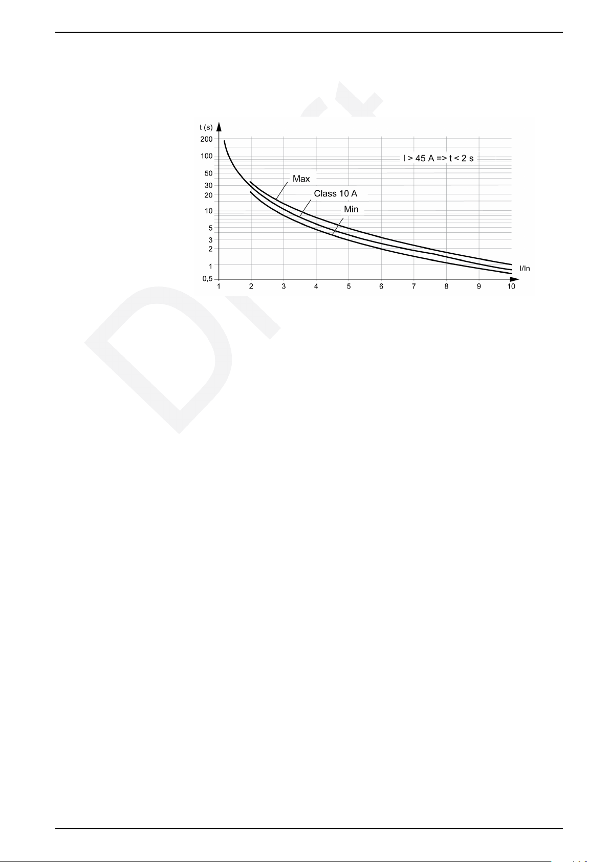
If the current exceeds 45 A for more than 2 s, the TeSys H motor starter switches
off the motor and indicates the cause of the trip through the TRIP/ERR LED and
trip signaling contact.
Diagnostic Functions
The following errors are detected by the TeSys H motor starter:
• Two or more phases are missing.
• No motor is connected.
• On at least two phases, the motor current is lower than the minimum
configurable current for more than 2 s.
12 DOCA0111EN-03
Page 13
L1
1/L12/T1
L2
3/L2
A1
4/T2
L3
5/L3
A2
98Y296Y195
Y3
6/T3
a(L) / +
F1
a(N) / -
LZ1Hppppp
LZ2Hppppp
M
3a
PE
A
I.1
I.2
Motor Control Applications TeSys Control - Hybrid Motor Starter
Motor Control Applications
Motor Control Using a Standard TeSys H Motor Starter
Overview
NOTICE
HAZARD OF EQUIPMENT DAMAGE
• Connect the TeSys H motor starter as specified in the wiring diagrams.
• The cable (A), used to connect the motor to the TeSys H, must be shielded if
the conductor length is greater than 8 m (26 ft) or in an environment with
electromagnetic disturbance.
• The length of conductors to connect terminals Y1, Y2, and Y3 must be less
than 30 m (98.4 ft).
Failure to follow these instructions can result in equipment damage.
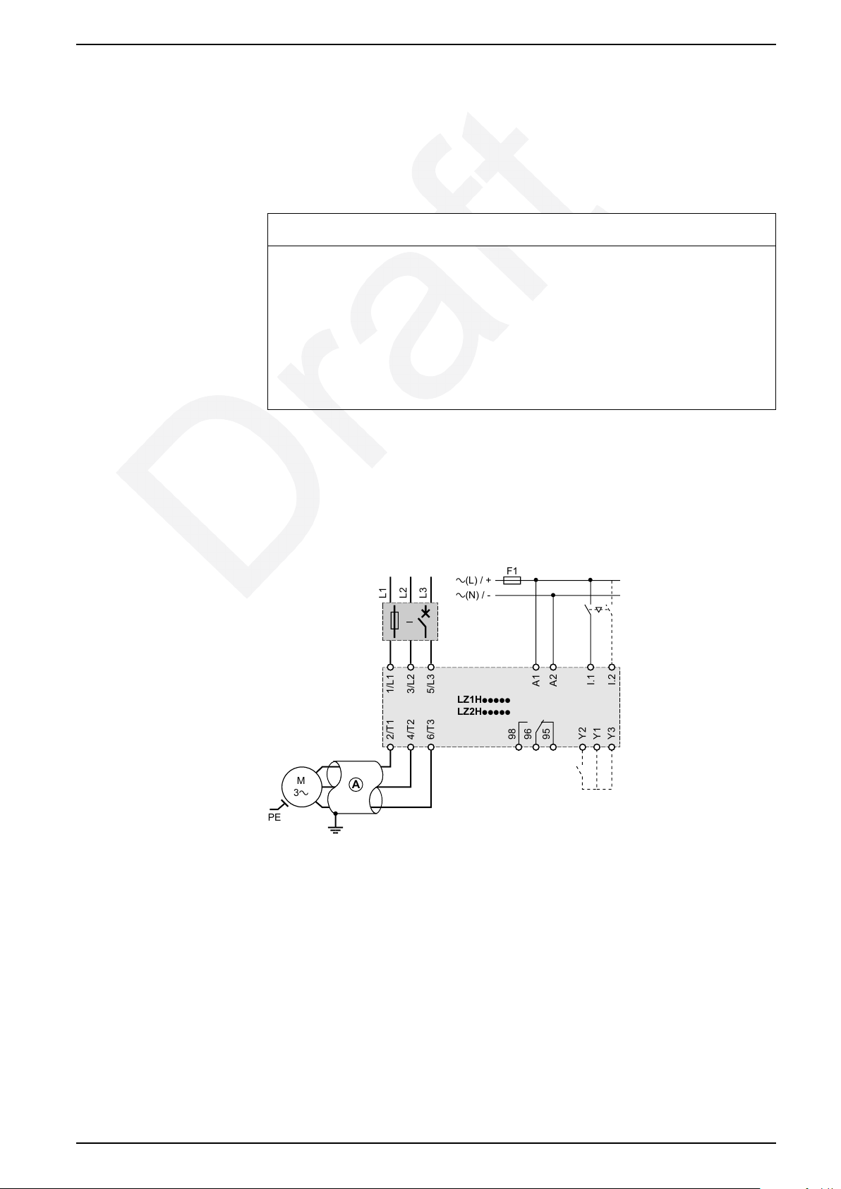
This section provides an example circuit for a DOL motor, using an LZ1H or LZ2H,
non-STO, TeSys H motor starter.
Three-Phase Motor Without Brake
This example wiring diagram is for a 3-phase motor without a brake.
A. Shielded cable, for cable length greater than 8 m (26 ft), or in an environment
with electromagnetic disturbance.
One of the following optional reset functions can be wired on terminals Y1, Y2,
and Y3 :
• Remote reset by a normally open (NO) contact, page 32
• Automatic reset, page 32
DOCA0111EN-03 13
Page 14

TeSys Control - Hybrid Motor Starter Motor Control Applications
Recommended Circuits for Motor Control in Safety Chain Applications Using an STO TeSys H Motor Starter
Overview
NOTICE
HAZARD OF EQUIPMENT DAMAGE
Connect the TeSys H motor starter as specified in the wiring diagrams.
Failure to follow these instructions can result in equipment damage.
This section provides recommended circuits for safe shutdown of motors that use
an STO TeSys H motor starter. In recommended circuits, shutdown is
achieved by interrupting the control input on I1 or I2.
The circuits in this section are for applications where safe shutdown is a normal
operating state, such as guard door applications and two-hand control
applications.
The following shutdown applications are included in this section:
• Dual-channel applications with a TM3SAC safety processing device - cat.3,
PLd according to EN ISO 13849:2006 and SIL 2 according to EN IEC
62061:2005 , page 15
• Dual-channel applications with a TM3SAF53 safety processing device - cat.4,
PLE according to EN ISO 13849:2006 and SIL 3 according to EN IEC
62061:2005, page 16
• Dual-channel input and single-channel output with an XPSAC safety
processing device - cat.3, PLd according to EN ISO 13849:2006 and SIL 2
according to EN IEC 62061:2005, page 17
• Dual-channel input and dual-channel output with an XPSAF safety processing
device - cat.4, PLE according to EN ISO 13849:2006 and SIL 3 according to
EN IEC 62061:2005, page 18
• Dual-channel and extended XPSMCM modular safety controller - cat.3, PLd
according to EN ISO 13849:2006 and SIL 2 according to EN IEC 62061:2005,
page 19
• Dual-channel and extended XPSMCM modular safety controller - cat.4, PLE
according to EN ISO 13849:2006 and SIL 3 according to EN IEC 62061:2005,
page 20
Implementation
You can implement single-channel or dual-channel configurations. Route the input
wiring for the direction 1 or direction 2 activation terminal and the corresponding
ground, through the safety processing device.
For dual-channel configurations, leave a switching time of 180 ms when switching
between direction 1 (forward) and direction 2 (reverse).
If cross-error exclusion is not allowed, cut off the supply voltage with a dualchannel or two-pole configuration. The supply voltage to the motor starter is cut off
with a single-channel configuration. Therefore, use this type of installation for SIL
3 (category 3, category 4) only if cross-error exclusions are allowed. For example,
use this type of installation when the motor starter and the safety processing
device are installed in the same control panel.
14 DOCA0111EN-03
Page 15
Motor Control Applications TeSys Control - Hybrid Motor Starter
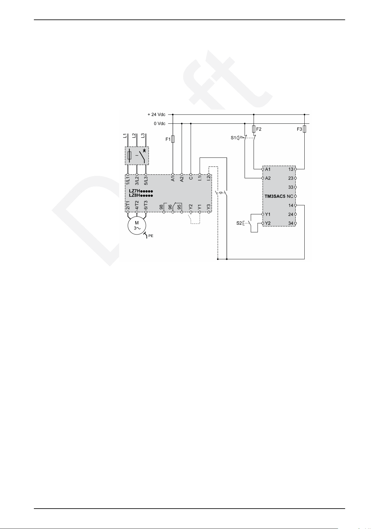
Dual-Channel Applications with a TM3SAC Safety Processing
Device - Cat.3, PLd According to EN ISO 13849:2006 and SIL 2
According to EN IEC 62061:2005
This dual-channel safety chain application uses the following modules:
• Emergency stop or guard
• TM3SAC safety processing device
• STO TeSys H motor starter
S1 Emergency stop button with two NC contacts, Harmony XB4 or safety limit
switches Preventa XCS.
S2 Start button.
NOTE: When a jumper is installed between TM3SAC terminals Y1 and Y2, the
motor restarts automatically.
DOCA0111EN-03 15
Page 16
TeSys Control - Hybrid Motor Starter Motor Control Applications
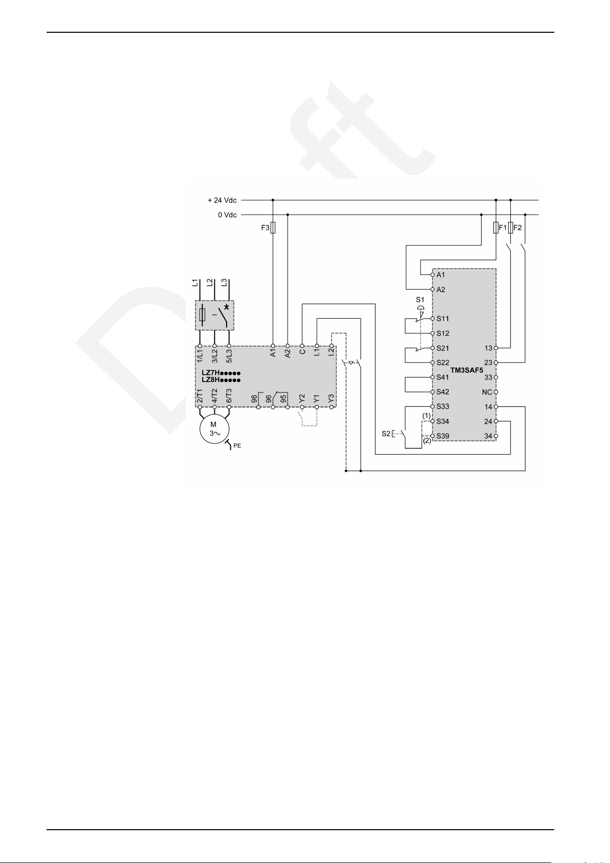
Dual-Channel Applications with a TM3SAF53 Safety Processing
Device - Cat.4, PLE According to EN ISO 13849:2006 and SIL 3
According to EN IEC 62061:2005
This dual-channel safety chain application uses the following modules:
• Emergency stop or guard
• TM3SAF53 safety processing device
• STO TeSys H motor starter
S1 Emergency STOP button with two NC contacts, Harmony XB4 or Preventa
XCS safety limit switches
S2 Start button: (1) monitored start, (2) non-monitored start
NOTE: When a jumper is installed between S33 and S39, the motor restarts
automatically.
16 DOCA0111EN-03
Page 17
Motor Control Applications TeSys Control - Hybrid Motor Starter
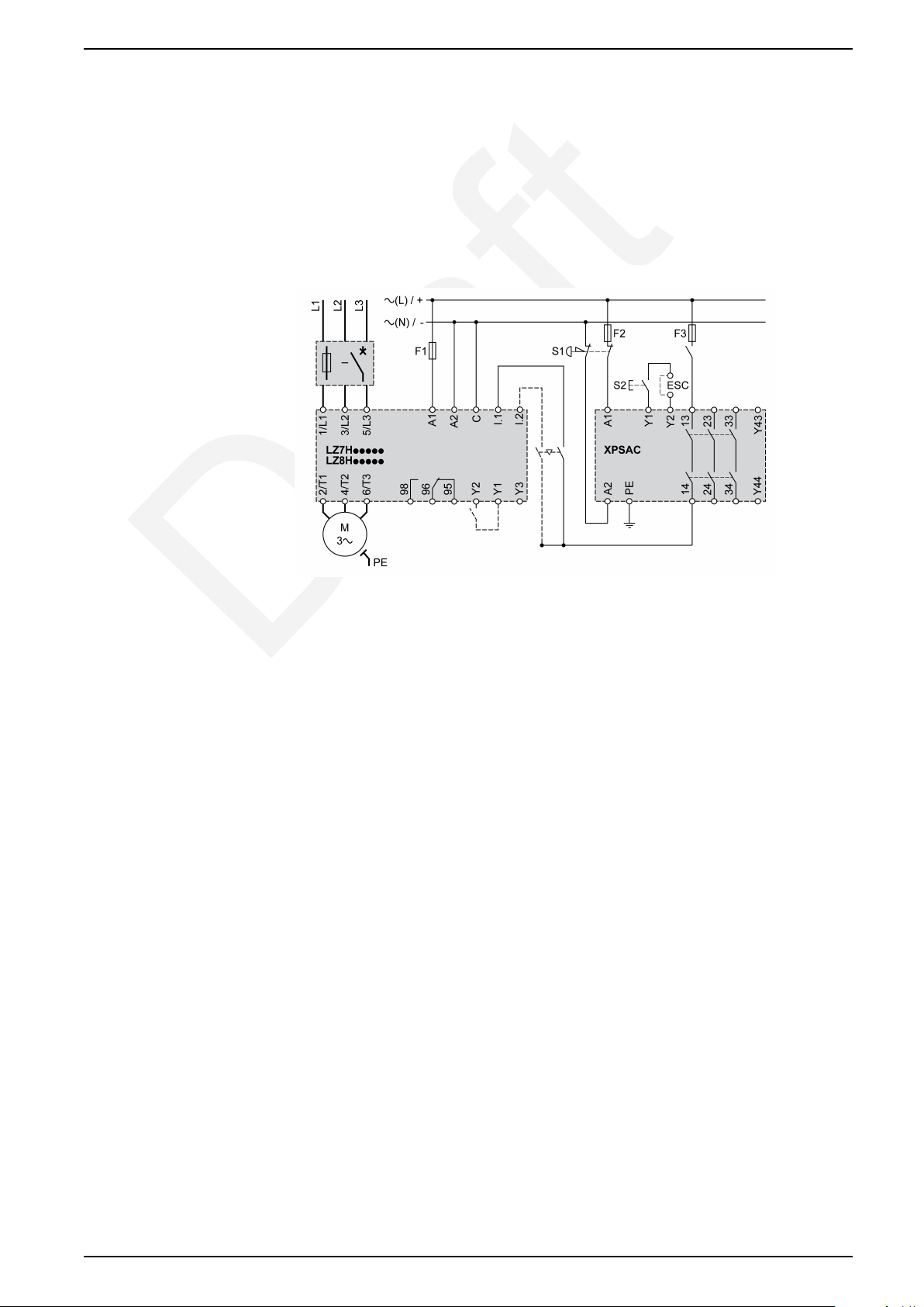
Dual-Channel Input and Single-Channel Output with an XPSAC
Safety Processing Device - Cat.3, PLd According to EN ISO
13849:2006 and SIL 2 According to EN IEC 62061:2005
This dual-channel input, single-channel output safety chain application, uses the
following modules:
• Emergency stop or guard
• Preventa XPSAC safety processing device
• STO TeSys H motor starter
S1 Emergency STOP pushbutton with two NC contacts
S2 Start button
ESC External start conditions
DOCA0111EN-03 17
Page 18
TeSys Control - Hybrid Motor Starter Motor Control Applications
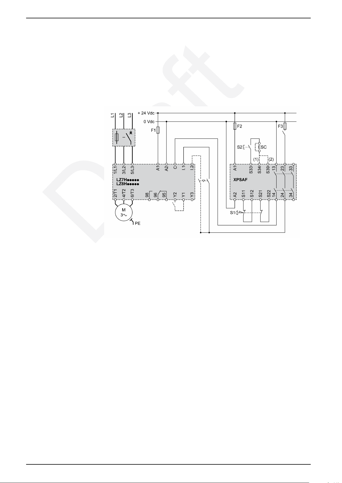
Dual-Channel Input and Dual-Channel Output with an XPSAF
Safety Processing Device - Cat.4, PLE According to EN ISO
13849:2006 and SIL 3 According to EN IEC 62061:2005
This dual-channel input, dual-channel output safety chain application uses the
following modules:
• Emergency stop or guard
• Preventa XPSAF safety processing device
• STO TeSys H motor starter
S1 Emergency STOP pushbutton with two NC contacts
S2 Start button
ESC External start conditions: (1) with monitoring of the start button, (2) without
monitoring of the start button
18 DOCA0111EN-03
Page 19
Motor Control Applications TeSys Control - Hybrid Motor Starter
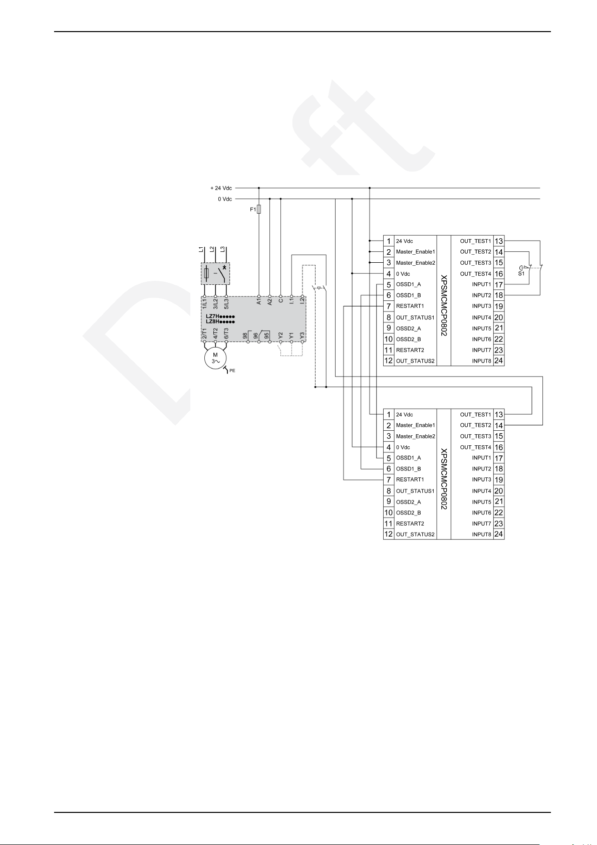
Dual-Channel and Extended XPSMCM Modular Safety Controller Cat.3, PLd According to EN ISO 13849:2006 and SIL 2 According
to EN IEC 62061:2005
This dual-channel safety chain application uses the following modules:
• Emergency stop or guard
• XPSMCM modular safety controller
• STO TeSys H motor starter
DOCA0111EN-03 19
Page 20

TeSys Control - Hybrid Motor Starter Motor Control Applications
Dual-Channel and Extended XPSMCM Modular Safety Controller Cat.4, PLE According to EN ISO 13849:2006 and SIL 3 According
to EN IEC 62061:2005
This dual-channel safety chain application uses the following modules:
• Emergency stop or guard
• Extended XPSMCM modular safety controller
• STO TeSys H motor starter
20 DOCA0111EN-03
Page 21

Motor Control Applications TeSys Control - Hybrid Motor Starter
Additional Circuits for Motor Control in Safety Chain Applications Using an STO TeSys H Motor Starter
Overview
NOTICE
HAZARD OF EQUIPMENT DAMAGE
Connect the TeSys H motor starter as specified in the wiring diagrams.
Failure to follow these instructions can result in equipment damage.
This section provides additional circuits for safe shutdown of motors that use an
STO TeSys H motor starter. In these additional circuits, shutdown is achieved by
cutting off the power supply on terminal A1 or A2. Repeated shutdown of
applications that use these circuits reduces the electrical life of the motor
starter to 10,000 cycles.
The circuits in this section are for emergency situations. As soon as the
emergency stop button is pushed, the supply voltage is cut off with a safety
processing device. The motor voltage is cut off 25 ms after the rated control
voltage is cut off.
Implementation
The following shutdown applications are included in this section:
• Dual-channel input and single-channel output with an XPSAC safety
processing device - cat.3, PLd according to EN ISO 13849:2006 and SIL 2
according to EN IEC 62061:2005, page 22
• Dual-channel input and dual-channel output with an XPSAC safety processing
device - cat.3, PLd according to EN ISO 13849:2006 and SIL 2 according to
EN IEC 62061:2005, page 23
If cross-error exclusion is not allowed, cut off the supply voltage with a dualchannel or two-pole configuration.
The supply voltage to the motor starter is cut off with a single-channel
configuration. Therefore, use this type of installation for SIL 3 (category 3,
category 4) only if cross-error exclusions are allowed. For example, use this type
of installation when the motor starter and the safety processing device are
installed in the same control panel.
DOCA0111EN-03 21
Page 22
TeSys Control - Hybrid Motor Starter Motor Control Applications
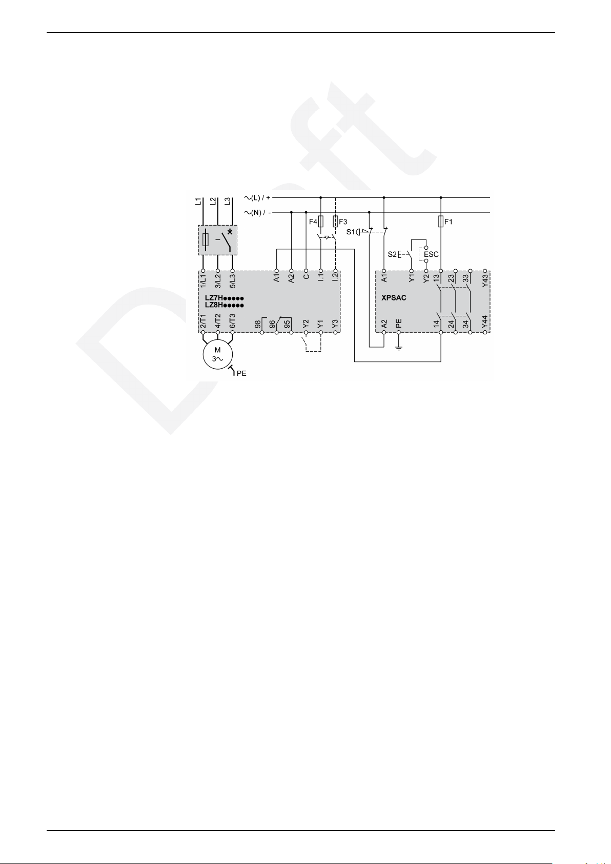
Dual-Channel Input and Single-Channel Output with an XPSAC
Safety Processing Device - Cat.3, PLd According to EN ISO
13849:2006 and SIL 2 According to EN IEC 62061:2005
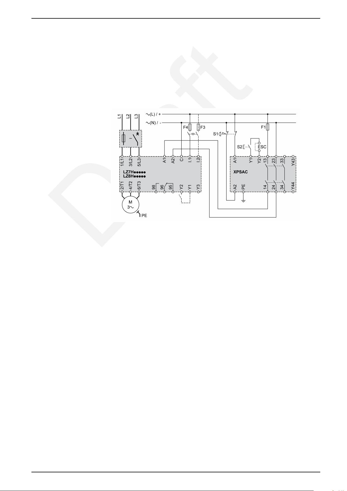
This dual-channel input, single-channel output, safety chain application uses the
following modules:
• Emergency stop
• Preventa XPSAC safety processing device
• STO TeSys H motor starter
S1 Emergency stop button with two NC contacts
S2 Start button
ESC External start conditions
NOTE: When a jumper is installed between XPSAC terminals Y1 and Y2, the
motor restarts automatically.
22 DOCA0111EN-03
Page 23
Motor Control Applications TeSys Control - Hybrid Motor Starter
Dual-Channel Input and Dual-Channel Output with XPSAC Safety
Processing Device - Cat.3, PLd According to EN ISO 13849:2006
and SIL 2 According to EN IEC 62061:2005
This dual-channel input, dual-channel output, safety chain application uses the
following modules:
• Emergency stop
• Preventa XPSAC safety processing device
• STO TeSys H motor starter
S1 Emergency stop button with two NC contacts
S2 Start button
ESC External start conditions
NOTE: When a jumper is installed between XPSAC terminals Y1 and Y2, the
motor restarts automatically.
DOCA0111EN-03 23
Page 24
TeSys Control - Hybrid Motor Starter Motor Control Applications
Motor Control Using a Standard or STO Motor Starter for Motors with Brake
Overview
CAUTION
OVERHEATING
When you connect and operate motors with built-in brakes, be aware of the
hazard of overheating. The energy to release the brakes is taken from the motor
connection cables, which can cause asymmetrical power consumption and
result in overheating.
Failure to follow these instructions can result in injury or equipment
damage.
CAUTION
UNINTENDED EQUIPMENT OPERATION
The current setting of the TeSys H motor starter must be the nominal current of
the motor increased by the value of the brake nominal current.
Failure to follow these instructions can result in injury or equipment
damage.
NOTICE
HAZARD OF EQUIPMENT DAMAGE
Connect the TeSys H motor starter as specified in the wiring diagrams.
Failure to follow these instructions can result in equipment damage.
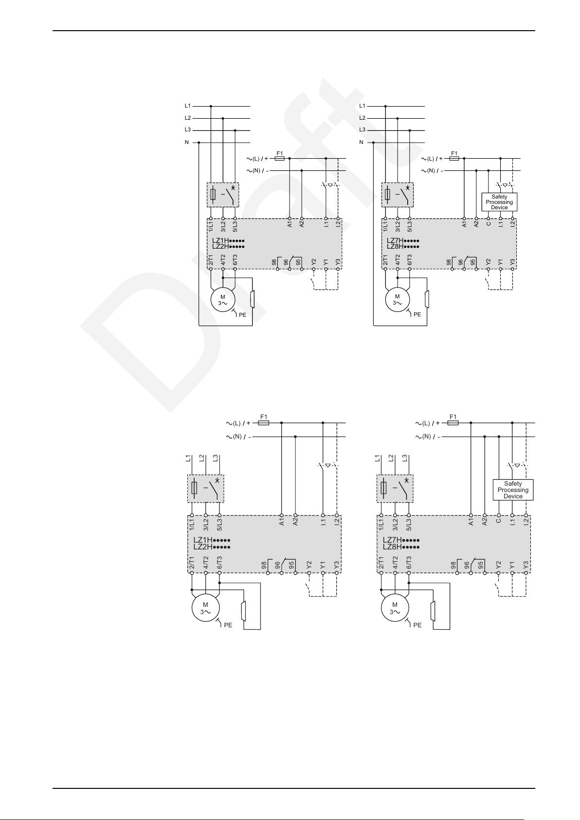
This section provides circuits for motors with a brake. The wiring diagram you use
depends on voltage supply of the brake, either 230 Vac or 400 Vac.
Activate external brakes by using a separate contactor, such as TeSys D.
24 DOCA0111EN-03
Page 25
L1
L2
L3
N
F1
(N)
(L)
1/L12/T1
4/T2
6/T3
PE
M
3
98
96
95
Y2
Y1
Y3
5/L3
A1
A2
I.1
I.2
3/L2
LZ1H·····
LZ2H·····
L1
L2
L3
N
F1
(N)
(L)
1
/L1
2
/T1
4/T2
6/T3
98
96
95
Y2
Y1
Y3
5/L3
A1
A2
C
I.1
I.2
3/L2
LZ7H·····
LZ8H·····
Safety
Processing
Device
PE
M
3
F1
(N)
(L)
1/L12/T1
4/T2
6/T3
PE
M
3
98
96
95
Y2
Y1
Y3
5/L3
L1
L2
L3
A1
A2
I.1
I.2
3/L2
LZ1H·····
LZ2H·····
F1
(N)
(L)
1/L12/T1
4/T2
6/T3
PE
M
3
98
96
95
Y2
Y1
Y3
5/L3
L1
L2
L3
A1
A2
C
I.1
I.2
3/L2
LZ7H·····
LZ8H·····
Safety
Processing
Device
Motor Control Applications TeSys Control - Hybrid Motor Starter
Three-Phase Motor Control with a 230 Vac Brake
The current for braking is taken from one phase and the neutral conductor.
Connect the brake to the neutral conductor and to the phase that goes to T2.
Three-Phase Motor Control with a 400 Vac Brake
The current for braking is taken from two phases. Connect the brake to the phases
that go to T1 and T3.
DOCA0111EN-03 25
Page 26

TeSys Control - Hybrid Motor Starter Operation
Operation
Commissioning
Power-Up
When you connect the TeSys H motor starter to the control supply, the four LEDs
flash for 1 s, stay lit for 1 s, and then go off. The location of the LEDs is shown in
the product description, page 10.
When you set the nominal current for the first time, the LEDs light up as indicated
in the following procedure. When you change the nominal current, the behavior of
the TeSys H motor starter and the sequence of LEDs depend on the state of the
TeSys H motor starter.
WARNING
HAZARD OF INADEQUATE MOTOR PROTECTION
The current setting of the TeSys H motor starter must be adapted in accordance
with the motor to be protected.
Failure to follow these instructions can result in death, serious injury, or
equipment damage.
Setting the Nominal Current for the First Time
Before you start the following procedure, make sure that the following conditions
are met:
• The TeSys H motor starter is powered up.
• The 110–230 Vac or 24 Vdc LED is on and the other LEDs are off.
• No run commands are on control inputs I1 or I2.
Step Action
1 Lift the cover on the front of the TeSys H motor starter to access the SET/RESET button.
2 Press and hold down the SET/RESET button for at least 6 s.
After 6 s the 110–230 Vac or 24 Vdc LED flashes once.
3 Release the SET/RESET button.
4 Turn the potentiometer to select an approximate nominal current, and then fine-tune the position until the LEDs indicate the
exact nominal current that you want.
The LEDs light up in a combination that indicates the nominal current. See the table of LED combinations and
corresponding nominal current, page 27.
5
6 Drop the cover back over the front of the TeSys H motor starter.
Press the SET/RESET button to save the selected nominal current.
The 110–230 Vac or 24 Vdc LED comes on and the other LEDs go off.
NOTE: The factory setting for LZ.H2X4 is 0.18 A. The factory setting for LZ.
H6X5 is 1.5 A.
Changing the Nominal Current
Before you start, make sure that the following conditions are met:
• The TeSys H motor starter is powered up.
26 DOCA0111EN-03
Page 27
Operation TeSys Control - Hybrid Motor Starter
• The 110–230 Vac or 24 Vdc LED is on and the other LEDs are off.
• No run commands are on control inputs I1 or I2.
Step Action
1 Lift the cover on the front of the TeSys H motor starter to access the SET/RESET button.
2 Press and hold down the SET/RESET button for at least 6 s.
When you are holding the button down, the LEDs flash in a combination that indicates the normal current.
3 Release the SET/RESET button.
The LEDs stay lit.
4 Turn the potentiometer to select an approximate nominal current, and then fine-tune the position until the LEDs indicate the
5
6 Drop the cover back over the front of the TeSys H motor starter.
exact nominal current that you want. See the table of LED combinations and corresponding nominal current, page 27.
Press the SET/RESET button to save the selected nominal current.
The 110–230 Vac or 24 Vdc LED comes on and the other LEDs go off.
Checking the Nominal Current
Before you start, make sure that the following conditions are met:
• The TeSys H motor starter is powered up.
• The TRIP/ERR LED is off.
• No run commands are on control inputs I1 or I2.
Step Action
1 Lift the cover on the front of the TeSys H motor starter to access the SET/RESET button.
2 Press and hold down the SET/RESET button for 2–5 s.
When you are holding the button down, the LEDs flash in a combination that indicates the nominal current. See the table of
LED combinations and corresponding nominal current, page 27.
NOTE: If you hold down the SET/RESET button for more than 6 seconds, you start the procedure to set the nominal
current after the first time, page 26.
3 Drop the cover back over the front of the TeSys H motor starter.
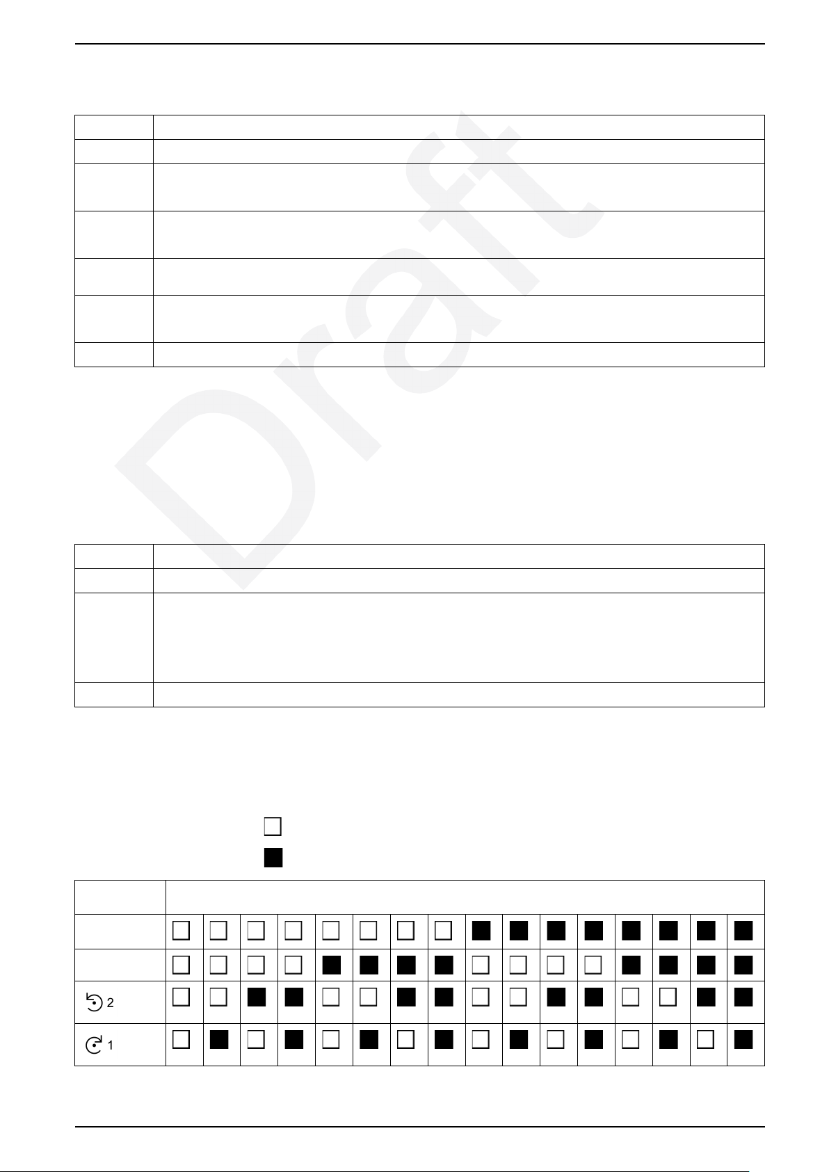
LED Combination and Corresponding Nominal Current
The following symbols indicate whether an LED is on or off.
LED off
LED on
Current/LED
name
110–230 Vac
or 24 Vdc
TRIP/ERR
Nominal current/LED combination
DOCA0111EN-03 27
Page 28

TeSys Control - Hybrid Motor Starter Operation
Current/LED
name
Setting range
0.18 A...2.4 A
Setting range
1.5 A...9 A
Nominal current/LED combination
0.18 0.25 0.41 0.56 0.71 0.87 1.02 1.17 1.33 1.48 1.63 1.79 1.94 2.09 2.25 2.4
1.5 2 2.5 3 3.5 4 4.5 5 5.5 6 6.5 7 7.5 8 8.5 9
28 DOCA0111EN-03
Page 29
Operation TeSys Control - Hybrid Motor Starter
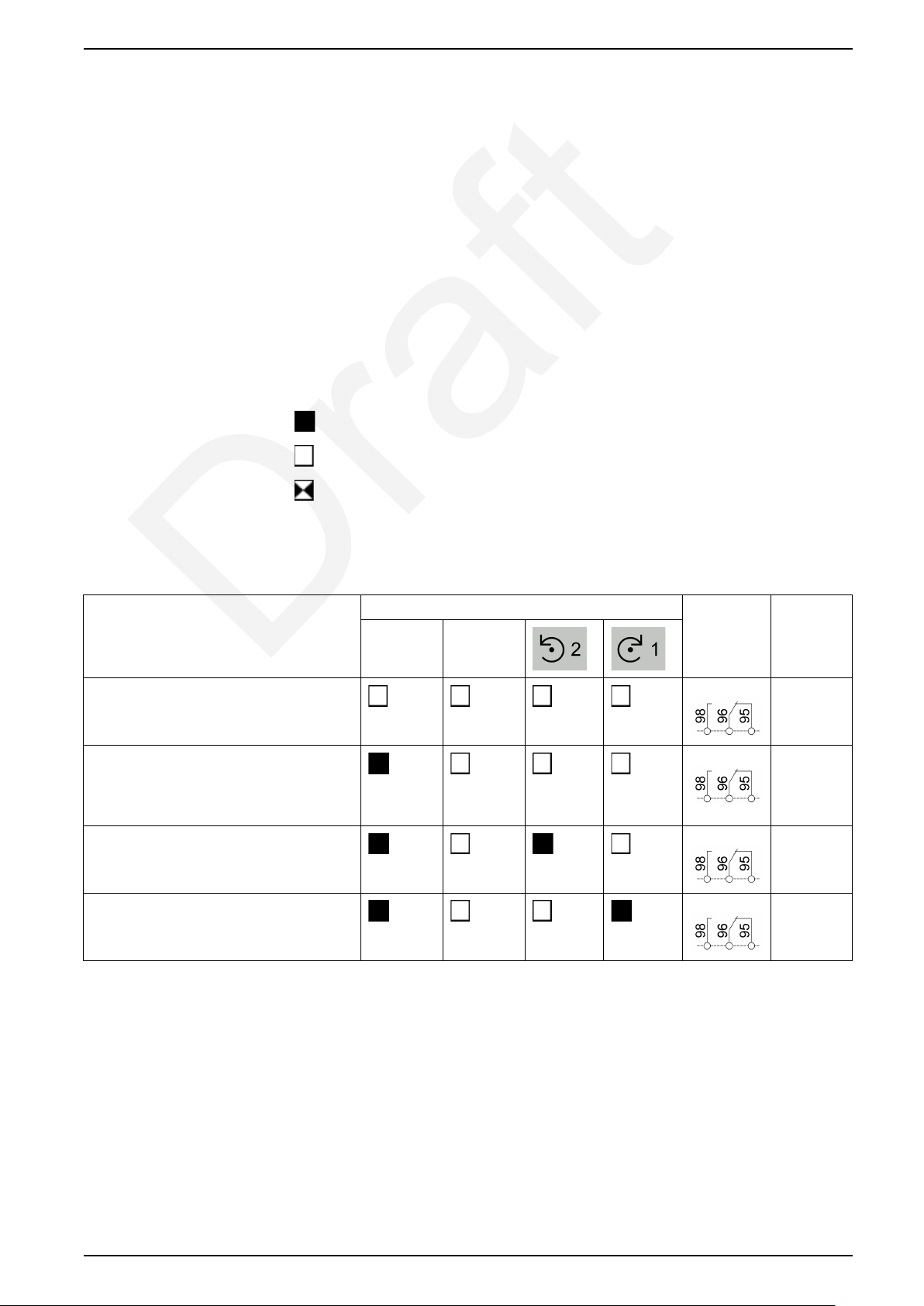
Diagnostic Functions
Overview
Use diagnostic functions to find the state of the TeSys H motor starter and
understand the cause of tripping. When there is a detected error or trip condition,
the device is in a safe, disconnected state.
Internal errors cannot be reset and are stored in the device. If more than 14
internal errors are detected, you can no longer operate the device.
Before you can leave the safe, disconnected state, you must reset the trip
condition. To reset an external error, push the SET/RESET button and release it
within 2 s.
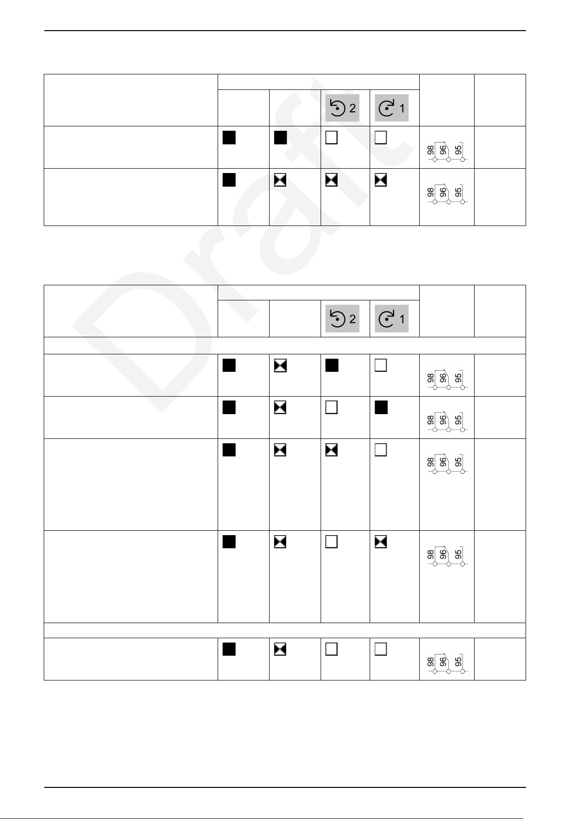
The tables in this section describe the combination of LED states, position of
signaling contacts, and reset possibilities, in normal conditions and trip or error
conditions. The following symbols indicate whether an LED is on, off, or flashing.
LED on
LED off
LED flashing at approximately 2 Hz (50:50)
Diagnostics for Normal Conditions
Description LED combination Signaling
110–230
Vac or 24
Vdc
Off
Not connected to the control supply, or control
supply is off.
Ready to start
Supply voltage is available. No trip or detected
error. The motor starter switches on when a run
command is given.
Running in direction 1
A command is on I2.
Running in direction 2
A command is on I1.
TRIP/ERR
contact
Reset
–
–
–
–
DOCA0111EN-03 29
Page 30
TeSys Control - Hybrid Motor Starter Operation
Diagnostics for Internal Error Conditions
Description LED combination Signaling
110–230
Vac or 24
Vdc
Internal error detected. The device must be
replaced.
Checksum error during determination of the
thermal system state.
The reset mode must be manual or remote. The
device does not reset if the reset mode is
automatic.
TRIP/ERR
contact
Diagnostics for Trip Conditions
Description LED combination Signaling
110–230
Vac or 24
Vdc
Thermal overload protection function
Overload trip occurred while the motor was
running in direction 2. Time to reset is counting
down. Reset is impossible.
TRIP/ERR
contact
Reset
Not
possible
Possible
Reset
Not
possible
Overload trip occurred while the motor was
running in direction 1. Time to reset is counting
down. Reset is impossible.
Overload trip occurred while the motor was
running in direction 2. Cool down period is in
progress.
If reset mode is manual or remote, reset is
possible.
If reset mode is automatic, device resets
automatically after the cool down period (20
minutes).
Overload trip occurred while the motor was
running in direction 1. Cool down period is in
progress.
If reset mode is manual or remote, reset is
possible.
If reset mode is automatic, device resets
automatically after the cool down period (20
minutes).
Phase unbalance
The motor currents differ from each other by
more than 33 %.
Manual or remote reset is possible immediately.
Not
possible
Possible
Possible
Possible
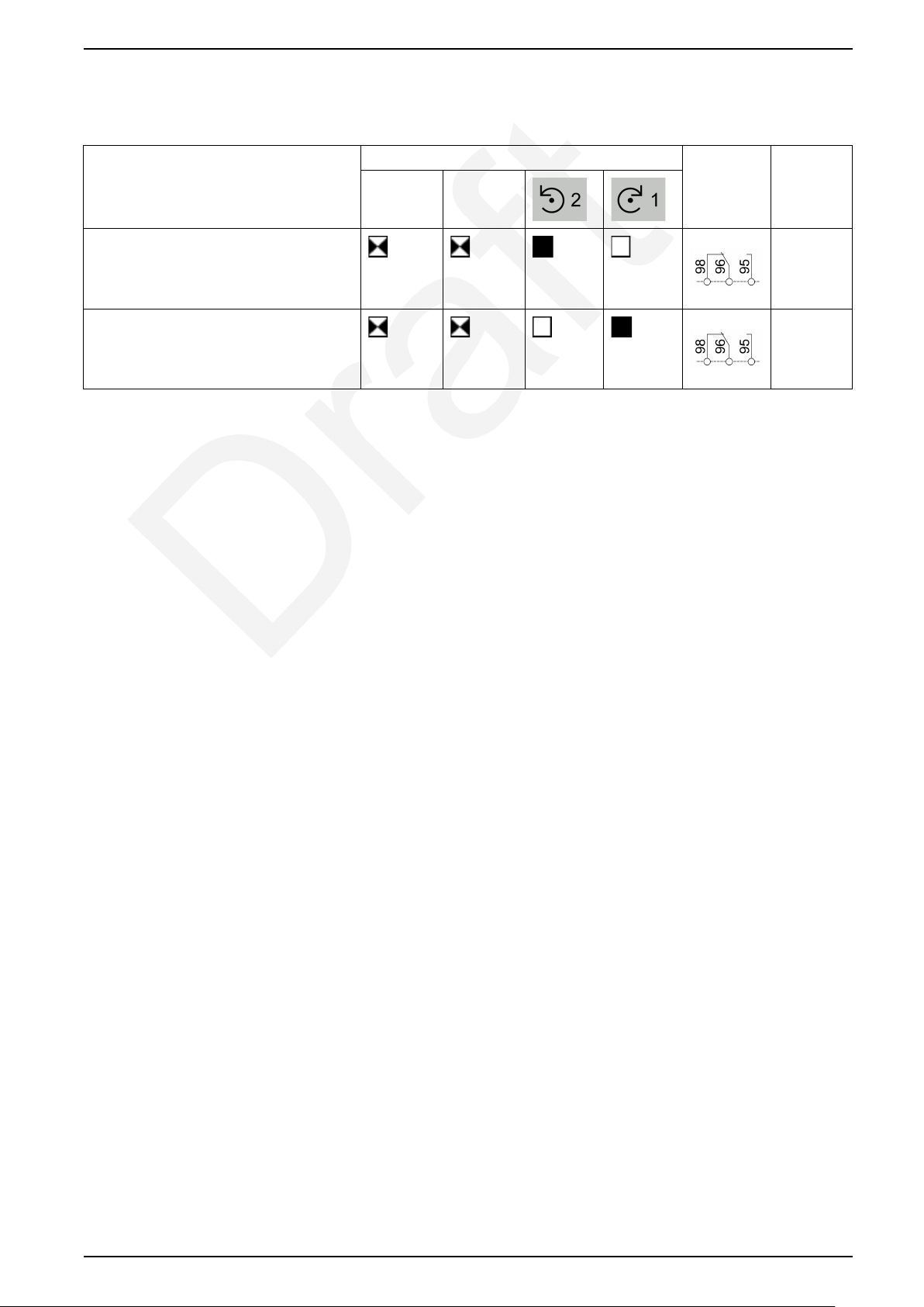
Diagnostics for Error Conditions
The following events can cause error conditions:
• Phase loss: two or more phases are missing.
30 DOCA0111EN-03
Page 31
Operation TeSys Control - Hybrid Motor Starter
• No connected motor.
• The motor current is lower than the minimum configurable current for more
than 2 seconds, on at least two phases.
Description LED combination Signaling
110–230
Vac or 24
Vdc
Error occurred while the motor was running in
direction 2.
When the phases return, the error is cleared
automatically.
Error occurred while the motor was running in
direction 1.
When the phases return, the error is cleared
automatically.
TRIP/ERR
contact
Reset
Not
required
Not
required
DOCA0111EN-03 31
Page 32
Y2
Y1 (1)
Y3
TeSys Control - Hybrid Motor Starter Operation
Resetting the TeSys H Motor Starter
Manual Reset with the SET/RESET Button
To reset the TeSys H motor starter manually, lift the cover and press the SET/
RESET button on the front of the device.
Wait for at least 2 minutes after the motor starter has tripped before you reset it.
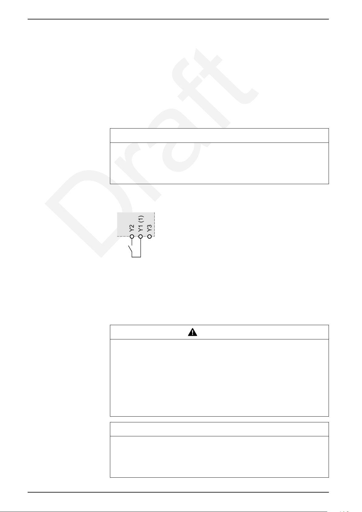
Remote Reset by a Normally Open (NO) Contact
NOTICE
HAZARD OF EQUIPMENT DAMAGE
The length of conductors used to connect terminals Y1, Y2 and Y3 must not be
more than 30 m (98.4 ft).
Failure to follow these instructions can result in equipment damage.
Automatic Reset
To reset the TeSys H motor starter remotely, connect a NO contact between
terminals Y1 and Y2.
Wait for at least 2 minutes after the starter motor has tripped before you reset it.
(1) The voltage of the common Y1 is equal to the power supply voltage of the
TeSys H motor starter.
WARNING
HAZARD OF AUTOMATIC START
• A motor connected to the circuit might start automatically in automatic reset
mode.
• For applications in the Ex-protection area, automatic reset mode is not
permitted.
• For emergency stop applications, the motor must be prevented from
restarting automatically by a higher-level control system.
Failure to follow these instructions can result in death, serious injury, or
equipment damage.
NOTICE
HAZARD OF EQUIPMENT DAMAGE
The length of conductors used to connect terminals Y1, Y2 and Y3 must be less
than 30 m (98.4 ft).
Failure to follow these instructions can result in equipment damage.
32 DOCA0111EN-03
Page 33

Y2
Y1 (1)
Y3
Operation TeSys Control - Hybrid Motor Starter
To reset the TeSys H motor starter automatically, install a jumper between the Y1
and Y3 terminals.
The motor starter resets automatically after 20 minutes. It is possible to reset the
motor starter manually or remotely after two minutes, if required.
(1) The voltage of the common Y1 is equal to the power supply voltage of the
TeSys H motor starter.
DOCA0111EN-03 33
Page 34

TeSys Control - Hybrid Motor Starter Operation
Protecting the Environment
Package Recycling
The packaging materials from this equipment can be recycled. Help to protect the
environment by recycling them in appropriate containers.
Thank you for playing your part in protecting the environment.
End-of-Life Recycling
This product has been optimized to decrease the amount of waste and valorize
the components and materials of the product in the usual end of life treatment
process.
The design has been achieved so that components are able to enter the usual
end-of-life treatment processes as appropriate: depollution if recommended, reuse
and/or dismantling if recommended to increase the recycling performances, and
shredding for separating the rest of materials.
34 DOCA0111EN-03
Page 35
Appendices TeSys Control - Hybrid Motor Starter
Appendices
Combining the TeSys H Motor Starter with Circuit Breakers
Overview
WARNING
HAZARDOUS VOLTAGE AT THE MOTOR
• Check the safety function each time the TeSys H motor starter trips.
• Replace the TeSys H motor starter after every short circuit in the case of
short-circuit protection according to type-1 coordination, and before
restarting the motor.
Failure to follow these instructions can result in death, serious injury, or
equipment damage.
For use in North America
WARNING
HAZARD OF FIRE OR ELECTRIC SHOCK
• The opening of the branch-circuit protective device may be an indication that
a fault current has been interrupted.
• To reduce the hazard of fire or electric shock, current-carrying parts and the
other components of the controller should be examined and replaced if
damaged.
Failure to follow these instructions can result in death, serious injury, or
equipment damage.
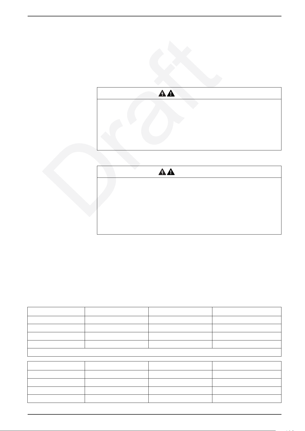
The TeSys H motor starter can be combined with the following magnetic motor
circuit breakers:
• GV2L: rotary knob type Ue = 500 V
• GV2LE: rocker lever type Ue = 415 V
Type-1 Coordination According to IEC/EN 60947-4-2 for 415 V
Maximum Voltage
TeSys H motor starter Iq short circuit current (kA) Circuit breaker reference Maximum current at 40 °C (A)
LZ••2X4•• 50 GV2L/GV2LE04 0.63
LZ••2X4•• 50 GV2L/GV2LE05 1
LZ••2X4•• 50 GV2L/GV2LE06 1.6
LZ••2X4•• 20 GV2L/GV2LE07 2.5
Data is valid at 40 °C
TeSys H motor starter Iq short circuit current (kA) Circuit breaker reference Maximum current at 40 °C (A)
LZ••6X5•• 50 GV2L/GV2LE06 1.6
LZ••6X5•• 20 GV2L/GV2LE07 2.5
LZ••6X5•• 10 GV2L/GV2LE08 4
LZ••6X5•• 7
DOCA0111EN-03 35
GV2L/GV2LE10 6.3
Page 36
TeSys Control - Hybrid Motor Starter Appendices
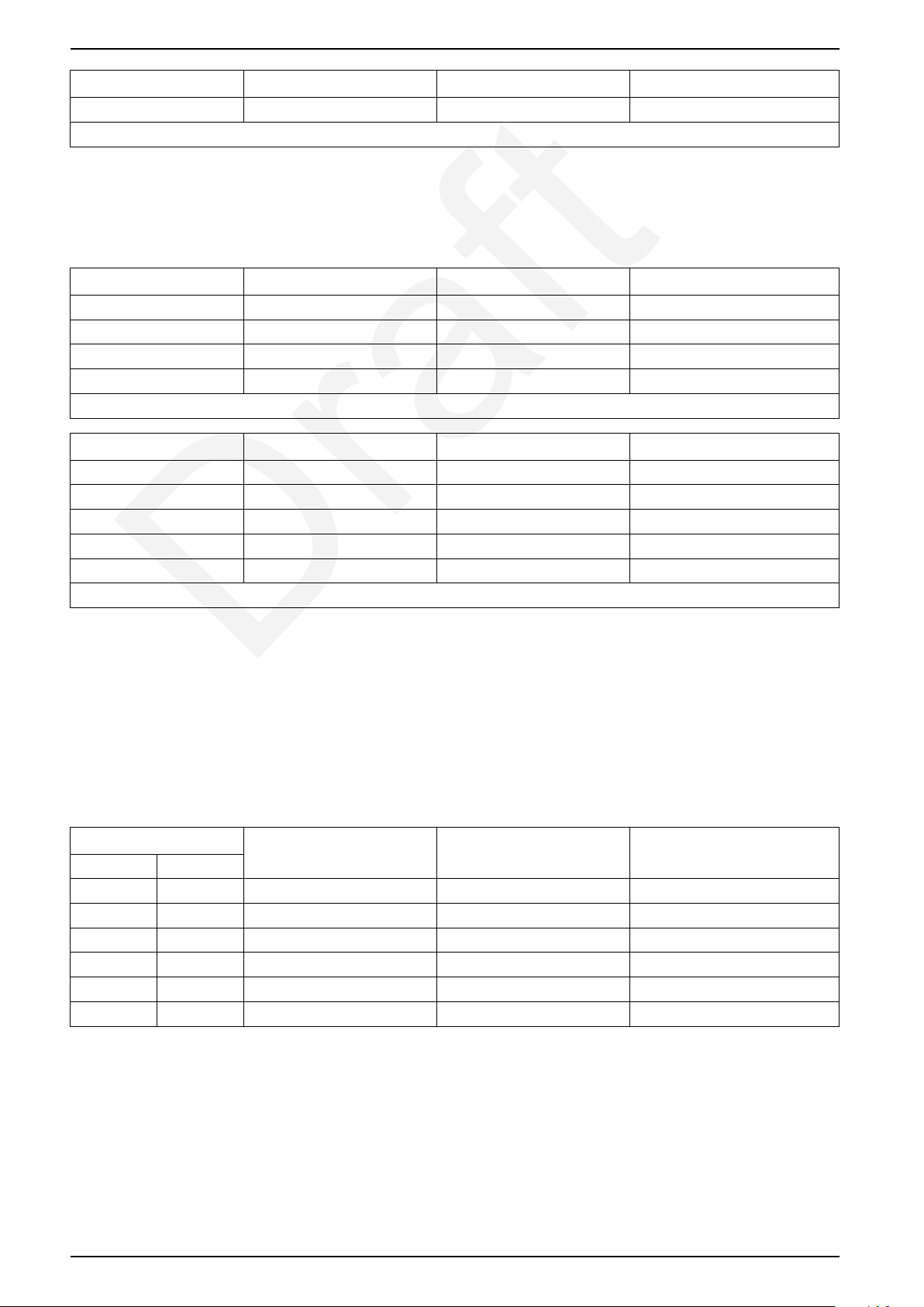
TeSys H motor starter Iq short circuit current (kA) Circuit breaker reference Maximum current at 40 °C (A)
LZ••6X5•• 7
Data is valid at 40 °C
GV2L/GV2LE14 10
Type-1 Coordination According to IEC/EN 60947-4-2 for 500 V
Maximum Voltage
TeSys H motor starter Iq short circuit current (kA) Circuit breaker reference Maximum current at 40 °C (A)
LZ••2X4•• 35 GV2L/GV2LE04 0.63
LZ••2X4•• 35 GV2L/GV2LE05 1
LZ••2X4•• 35 GV2L/GV2LE06 1.6
LZ••2X4•• 10 GV2L/GV2LE07 2.5
Data is valid at 40 °C
TeSys H motor starter Iq short circuit current (kA) Circuit breaker reference Maximum current at 40 °C (A)
LZ••6X5•• 35 GV2L/GV2LE06 1.6
LZ••6X5•• 10 GV2L/GV2LE07 2.5
LZ••6X5•• 8 GV2L/GV2LE08 4
LZ••6X5•• 4 GV2L/GV2LE10 6.3
LZ••6X5•• 3 GV2L/GV2LE14 10
Data is valid at 40 °C
Group Protection with Type-1 Coordination According to IEC/EN
60947-4-2 for 415 V Maximum Voltage
This table gives the maximum short circuit current that can be protected by
association of a GV2 circuit breaker and several TeSys H motor starters. The total
nominal current of all TeSys H motor starters combined together should not
exceed the maximum current of the GV2L/GV2LE circuit breaker associated for
group short circuit protection.
TeSys H motor starter Iq short circuit current (kA) Circuit breaker reference Maximum current at 40 °C (A)
2.4 A 6.5 A
LZ••2X4•• LZ••6X5•• 10 GV2L/GV2LE08 4
LZ••2X4•• LZ••6X5•• 7
LZ••2X4•• LZ••6X5•• 7
–
–
–
LZ••6X5•• 5
LZ••6X5•• 4 GV2L/GV2LE20 18
LZ••6X5•• 4 GV2L/GV2LE22 25
GV2L/GV2LE10 6.3
GV2L/GV2LE14 10
GV2L/GV2LE16 14
Group Protection with Type-1 Coordination According to IEC/EN
60947-4-2 for 500 V Maximum Voltage
This table gives the maximum short circuit current that can be protected by
association of a GV2 circuit breaker and several TeSys H motor starters. The total
nominal current of all TeSys H motor starters combined together should not
exceed the maximum current of the GV2L / GV2LE circuit breaker associated for
group short circuit protection.
36 DOCA0111EN-03
Page 37

Appendices TeSys Control - Hybrid Motor Starter
TeSys H motor starter Iq short circuit current (kA) Circuit breaker reference Maximum current at 40 °C (A)
2.4 A 6.5 A
LZ••2X4•• LZ•H6X5•• 8 GV2L/GV2LE08 4
LZ••2X4•• LZ•H6X5•• 4 GV2L/GV2LE10 6.3
LZ••2X4•• LZ•H6X5•• 3 GV2L/GV2LE14 10
–
–
–
LZ•H6X5•• 2 GV2L/GV2LE16 14
LZ•H6X5•• 2 GV2L/GV2LE20 18
LZ•H6X5•• 2 GV2L/GV2LE22 25
DOCA0111EN-03 37
Page 38
TeSys Control - Hybrid Motor Starter Appendices
Combining the TeSys H Motor Starter with Fuses
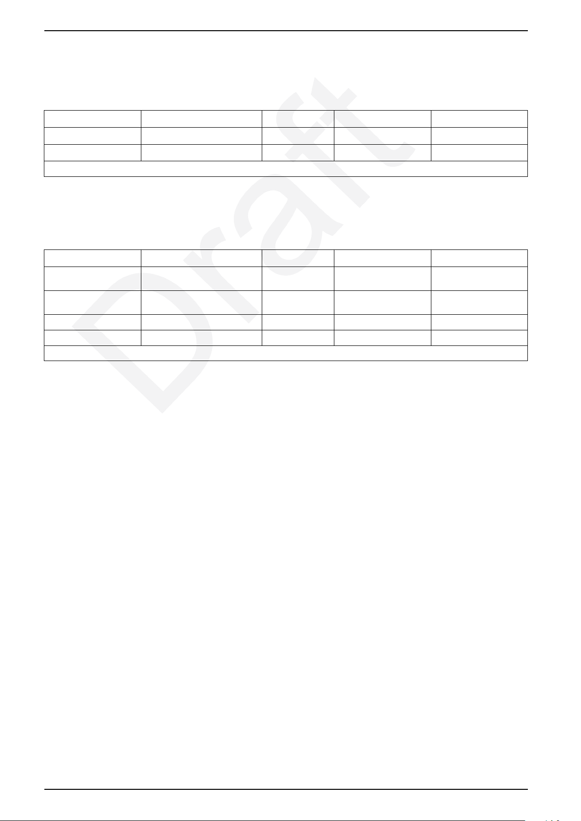
Type-1 Coordination According to IEC/EN 60947-4-2
TeSys H motor starter Iq short circuit current (kA) Protection type Maximum current (A) Maximum voltage (V)
LZ••2X4•• 10 Fuse gG 25 500
LZ••6X5•• 10 Fuse gG 25 500
Data is valid at 40 °C.
For Use in North America: Type-1 Coordination According to IEC/
EN 60947-4-2
TeSys H motor starter Iq short circuit current (kA) Protection type Maximum current (A) Maximum voltage (V)
LZ••2X4•• 100 Fuse class J or
CC
LZ••6X5•• 100 Fuse class J or
CC
LZ••2X4•• 5 Fuse RK5 20 500
LZ••6X5•• 5 Fuse RK5 20 500
Data is valid at 40 °C.
30 500
30 500
38 DOCA0111EN-03
Page 39
Appendices TeSys Control - Hybrid Motor Starter
Technical Data
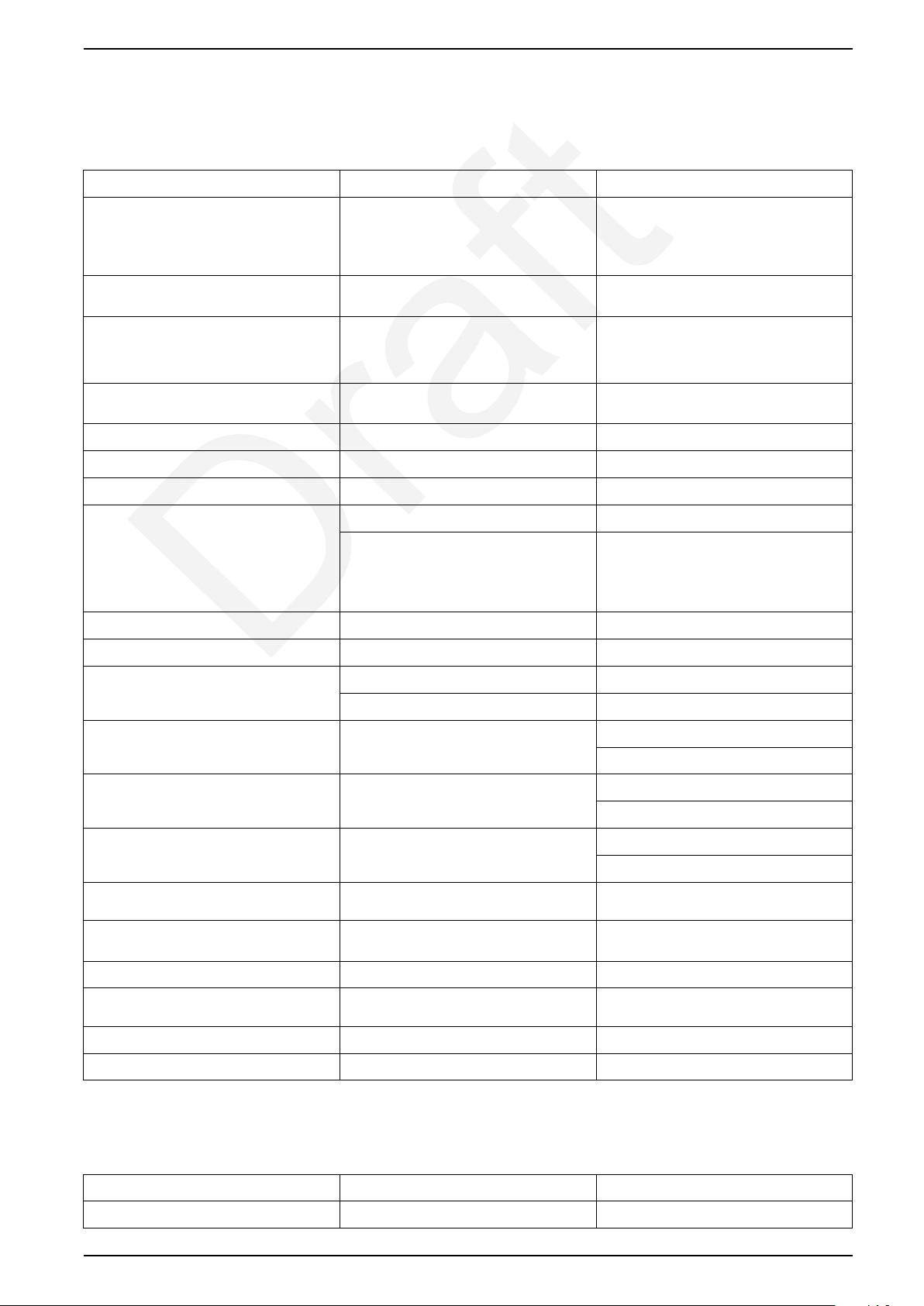
Environmental Characteristics
Characteristic Description Value
Rated insulation voltage (Ui) Conforming to IEC/EN 60947-1
Overvoltage category III
Degree of pollution: 2
Rated impulse withstand voltage (Uimp) Conforming to IEC/EN 60947-4-2 6 kV (24 Vdc control voltage); 4 kV (110–
Conformity to standards
Product certifications
Degree of protection Conforming to IEC/EN 60947-1 IP20
Environment category Conforming to IEC/EN 60947-1 E
Protective treatment Conforming to IEC/EN 60068-2-30 TC
Ambient air temperature around the device Storage -40 °C to +80 °C (-40 °F to 176 °F)
Maximum operating altitude Without derating 2,000 m (6,561 ft)
Operating positions
–
–
Operation
For information about derating curves
according to ambient temperature, refer to
derating characteristics, page 44.
–
500 V
230 Vac control voltage)
IEC/EN 60947-4-2, UL 60947-4-1,
and the standards used for ATEX (for STO
products)
CE, UKCA, cULus, ATEX (for STO
products), CCC (ongoing)
-25 °C to +70 °C (-13 °F to 158 °F)
Vertical axis (horizontal DIN rail)
Flame resistance of plastic parts Conforming to UL94 V0
Conforming to IEC/EN 60695-2-12 960 °C (1,760 °F)
Shock resistance 1/2 sine wave = 18 ms Conforming to IEC/EN 60068-2-27 30 g (30 gn) starter OFF
30 g (30 gn) starter ON
Vibration resistance
10–150 Hz
Resistance to electrostatic discharge Conforming to IEC/EN 61000-4-2 Air discharge: 8 kV
Immunity to radiated high-frequency
disturbance 80–1 GHz
Immunity to radiated high-frequency
disturbance 1.0–6 GHz (1,0–6 GHz)
Immunity to fast transient current Conforming to IEC/EN 61000-4-4 3 kV
Immunity to conducted high-frequency
disturbances
Radiated emission and conducted Conforming to CISPR11 and EN55011 Class A
Surge Conforming to IEC/EN 61000-4-5 1 kV symmetrical, 2 kV asymmetrical
Conforming to IEC/EN 60068-2-6 5 g (5 gn) starter OFF
5 g (5 gn) starter ON
Contact discharge: 6 kV
Conforming to IEC/EN 61000-4-3 20 V/m
Conforming to IEC/EN 61000-4-3 10 V/m
Conforming to IEC/EN 61000-4-6 10 V
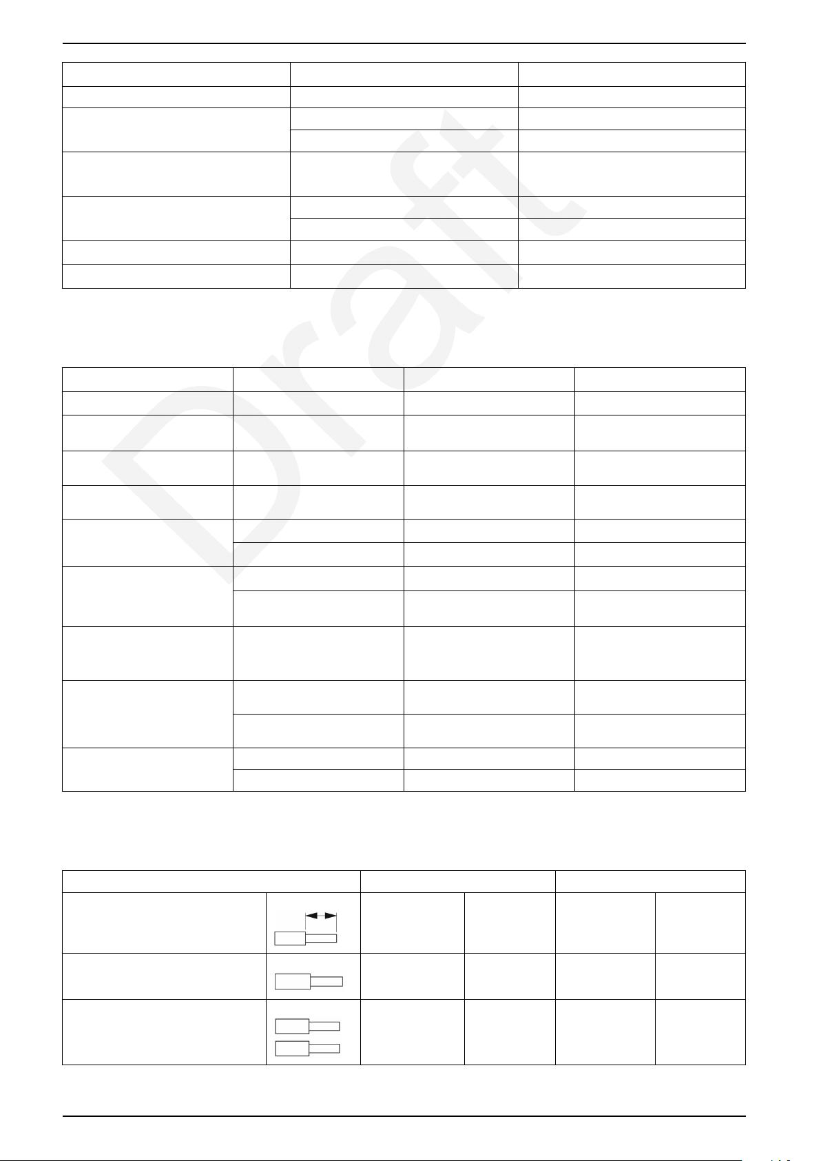
Control and Supply Circuit Characteristics
Characteristic Description Value
Rated voltage AC 50/60 Hz 110–230 V
DOCA0111EN-03 39
Page 40
TeSys Control - Hybrid Motor Starter Appendices
Characteristic Description Value
DC 24 V
Voltage limits AC 50/60 Hz 85–253 V
DC 19.2–30 V
Consumption
Operating time Switch on 35 ms
Voltage dips
Short time interruptions
–
Switch off 40 ms
–
–
45 mA for 24 Vdc
12 mA for 230 Vac
3 ms
3 ms
Power Circuit Characteristics
Characteristic Description LZ•H2X4•• LZ•H6X5••
Power dissipation
Rated operating current (see
derating curve)
–
–
0.88/4.1 W 0.88/7 W
0.18–2.4 A 1.5–9 A
AC51 Conforming to IEC/EN 60947-4-
AC53a Conforming to IEC/EN 60947-4-
Electrical life AC51 30,000,000 operations 30,000,000 operations
Maximum operating rate (ON/
OFF 50-50)
Maximum starting current in
AC53A
Coordination Conforming to IEC/EN 60947-4-
Time to restart motor after
overload trip
3
2
AC53A 30,000,000 operations 30,000,000 operations
AC51 7,200 operations/hr 7,200 operations/hr
AC53A Maximum Operating Rate for
–
2
Conforming to IEC/EN 60947-4-2Type 1 with fuses Type 1 with fuses
Manual or remote reset 2 minutes 2 minutes
Automatic reset 20 minutes 20 minutes
0.18–2.4 A 1.5–9 A
0.18–2.4 A 1.5–6.5 A
AC53A Duty, page 47
• 52 A for a single product
• 40 A for side-by-side
products
Type 1 with circuit breaker Type 1 with circuit breaker
Maximum Operating Rate for
AC53A Duty, page 47
• 52 A for a single product
• 40 A for side-by-side
products
Terminal Characteristics
Cable LZ•H••••• LZ•H•••3••
Length of stripped cable
Solid cable without cable end, and 1
conductor
Solid cable without cable end, and with
2 conductors of the same cross section
7 mm 0.28 in. 10 mm 0.39 in.
0.25–2.5 mm
0.25–0.75 mm
2
AWG 24–14 0.25–2.5 mm
2
AWG 24–20
– –
2
AWG 24–14
40 DOCA0111EN-03
Page 41
Appendices TeSys Control - Hybrid Motor Starter
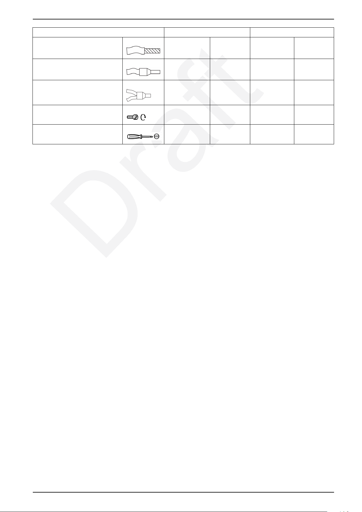
Cable LZ•H••••• LZ•H•••3••
Flexible cable without cable end, and
with 1 conductor
0.25–2.5 mm
2
AWG 24–14 0.25–2.5 mm
2
AWG 24–14
Flexible cable with cable end and 1
conductor
Flexible cables of the same cross
section, connected to a single twincable end
Tightening torque
Flat screwdriver
0.25–2.5 mm
0.25–1.5 mm
2
AWG 24–14 0.25–2.5 mm
2
AWG 24–16 0.25–1.5 mm
0.5–0.6 N.m 4.4–5.3 lb-in.
Diameter 3 mm Diameter
1/8 in.
2
2
– –
– –
AWG 24–14
AWG 24–16
DOCA0111EN-03 41
Page 42
TeSys Control - Hybrid Motor Starter Appendices
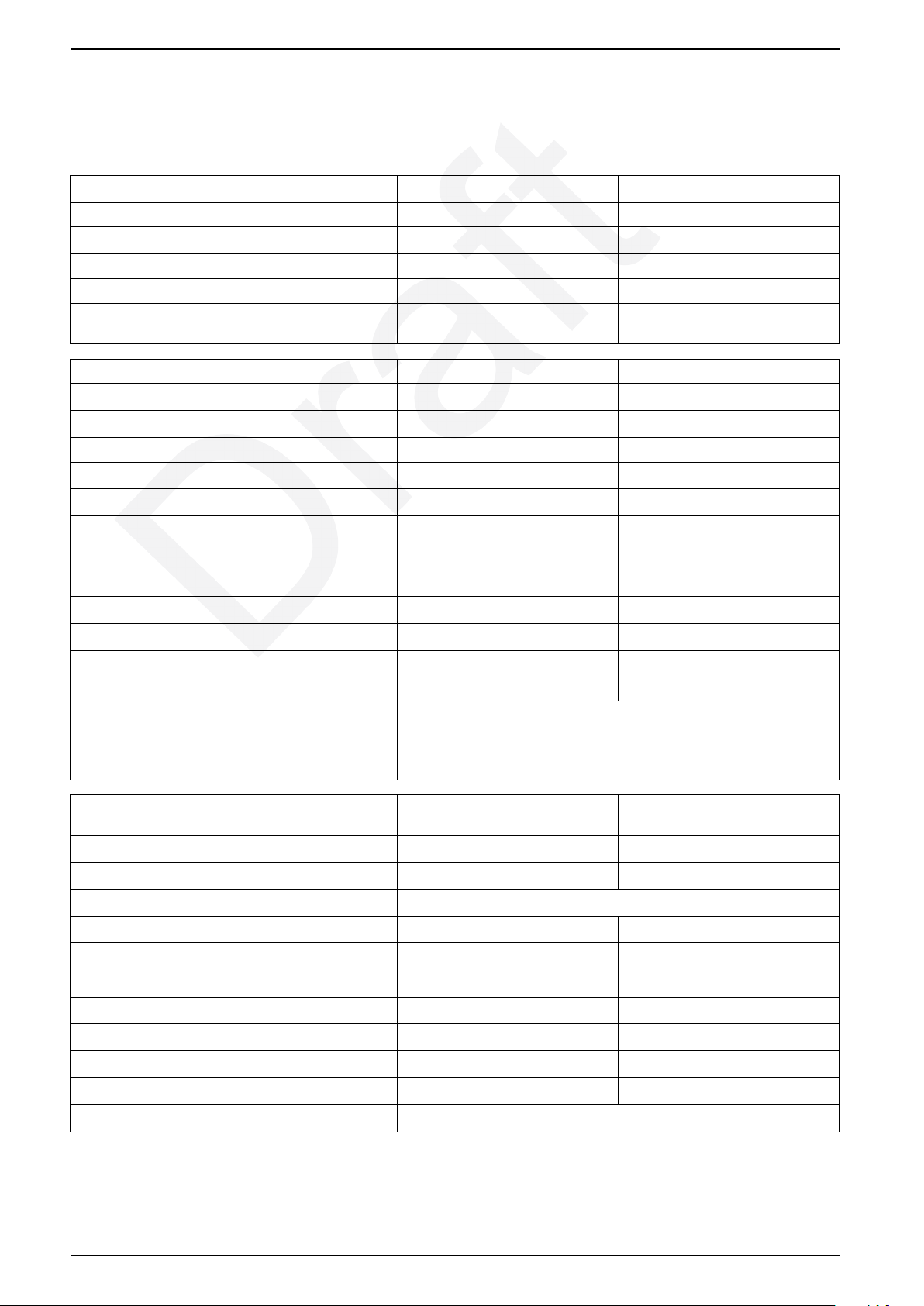
Safety Functions
Safety Functions
System conditions LZ7H or LZ8H 24 Vdc LZ7H or LZ8H 110/230 Vac
Database for failure rates SN 29500 SN 29500
System type Type B Type B
Standard used IEC 61508 IEC 61508
Beta factor 1 % 1 %
Mean time to failure (MTTFd) at an ambient temperature
40 °C (104 °F)
Safe switch-off LZ7H or LZ8H 24 Vdc LZ7H or LZ8H 110/230 Vac
Ambient temperature 40 °C (104 °F) 40 °C (104 °F)
Mean time to failure (MTTFd) 517 years 289 years
Switch-off time 80 100
λsd [FIT] safe, detectable 664 638
39.3 39.1
λsu [FIT] safe, undetectable 968 935
λdd [FIT] dangerous, detectable 218 388
λdu [FIT] dangerous, undetectable 2.67 6.82
SFF [%] Safe failure fraction 99 99
DCS [%] Diagnostic coverage safe 40.7 40.6
DC [%] Diagnostic coverage 98 98
PFHd probability of a dangerous failure per hour LZ7H: 2.40 x 10
LZ8H: 2.67 x 10
Safety level IEC/CEI 61508-1: SIL 3
ISO 13849-1: Category 3 PL e
EN 60954-1: Category 3
ATEX certified as associated device for motor
protection in zones 1 and 21
Ambient temperature 40 °C (104 °F) 40 °C (104 °F)
Mean time to failure (MTTFd) 447 years 273 years
Time to trip As for class 10 A, IEC/CEI 60947-4-2
λsd [FIT] safe, detectable 637 636
LZ7H or LZ8H 24 Vdc LZ7H or LZ8H 110/230 Vac
-9
-9
LZ7H: 6.27 x 10
LZ8H: 6.82 x 10
-9
-9
λsu [FIT] safe, undetectable 870 841
λdd [FIT] dangerous, detectable 239 402
λdu [FIT] dangerous, undetectable 17 17
SFF [%] Safe failure fraction 99 99
DCS [%] Diagnostic coverage safe 42.3 43.1
DC [%] Diagnostic coverage 93 95
Safety level IEC/CEI 61508-1: SIL 2
More safety information is available on request.
42 DOCA0111EN-03
Page 43
Appendices TeSys Control - Hybrid Motor Starter
Tripping Characteristics
Tripping Characteristics at 20 °C
DOCA0111EN-03 43
Page 44
Ta
In (A)
10 20 30
24 V DC
50
60
70
40
0
6
4
2
7
5
3
1
(°C)
LZpH6X5BD
LZpH2X4BD
0
LZpH6X5BD
1
1
2
2
50 68 86 104 122 140 15832
(°F)
50 68 86 104 122 140 15832
(°F)
Ta
In (A)
1
10 20 30
50
60
70
40
0
6
4
2
7
5
3
1
(°C)
0
LZpH6X5FU
LZpH2X4FU
LZpH6X5FU
110-230 V AC
2
2
1
TeSys Control - Hybrid Motor Starter Appendices
Derating Characteristics
Overview
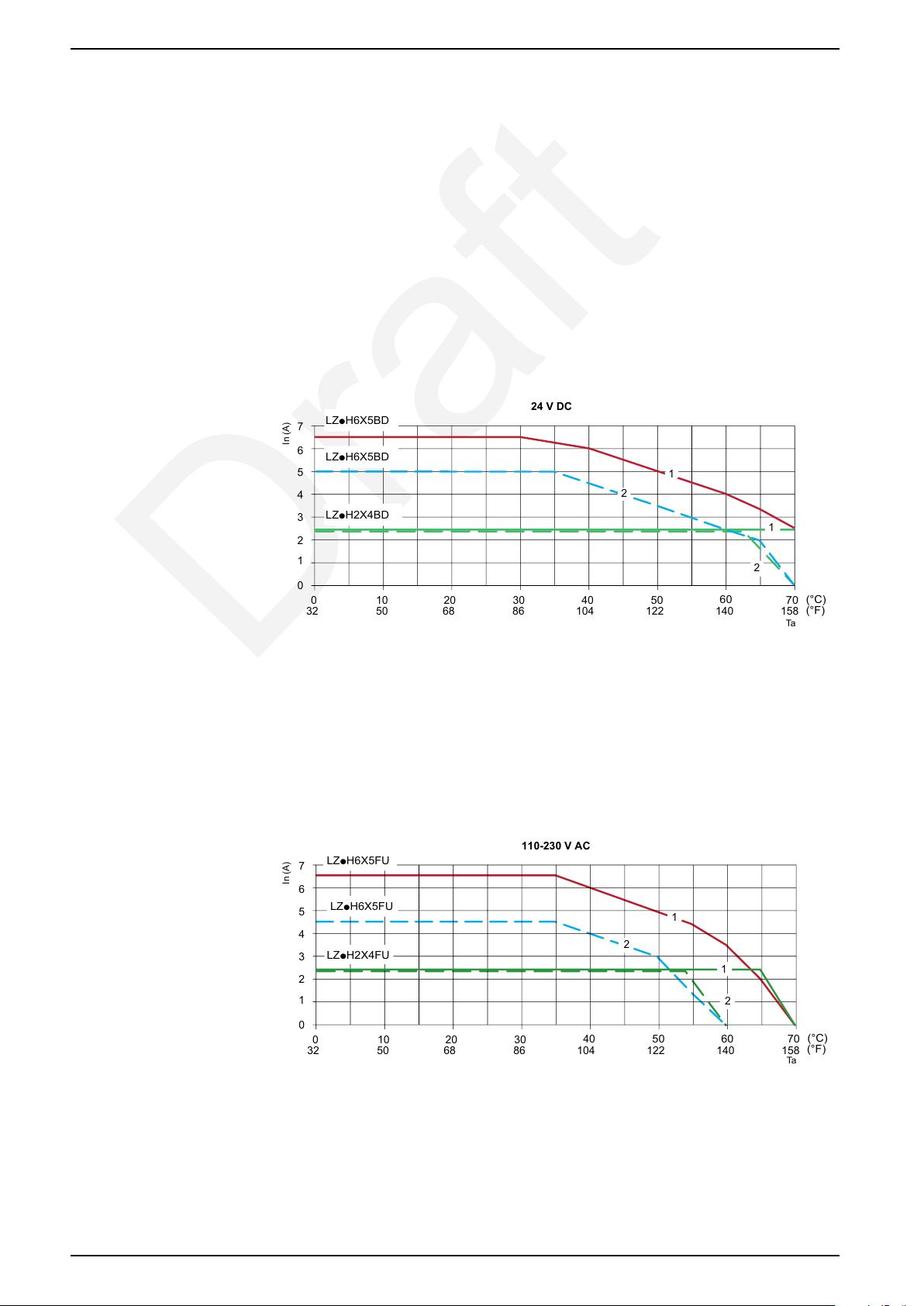
The curves in this section show the maximum load current for the following
parameters:
• Power supply
• Ambient temperature
• Distance between devices
Derating Characteristics for AC53A (Motor Application) Duty by
Temperature and Mounting Space for 24 Vdc
1 Distance between devices is 20 mm (0.51 in)
2 No space between devices
Derating Characteristics for AC53A (Motor Application) Duty by
Temperature and Mounting Space for 110–230 Vac
44 DOCA0111EN-03
1 Distance between devices is 20 mm (0.51 in)
2 No space between devices
Page 45
Appendices TeSys Control - Hybrid Motor Starter
Derating Characteristics for High-Efficiency Motors
TeSys H motor starters are designed for motors with a starting current (Is) that is
eight times the nominal current (Ie), according to IEC 60947-4-2. For these
motors, Is/Ie = 8.
The following tables list the maximum nominal current for motors where Is/Ie is
greater than or equal to 8. If necessary, limit the maximum nominal current of
these motors.
LX•2X4
Ratio of maximum starting current to nominal current (Is/le) 8 8.5 9 9.5 10
Nominal current (Ie) in A 2.4 2.4 2.4 2.4 2.4
LX•6X5
Ratio of maximum starting current to nominal current (Is/le) 8 8.5 9 9.5 10
Nominal current (Ie) in A 6.5 6 5.7 5.5 5.2
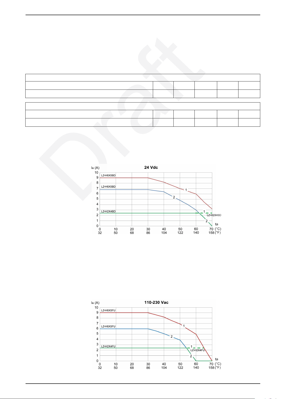
Derating Characteristics for AC51 (Resistive Load) Duty by
Temperature and Mounting Space for 24 Vdc
1 Distance between devices is 20 mm (0.51 in)
2 No space between devices
Derating Characteristics for AC51 (Resistive Load) Duty by
Temperature and Mounting Space for 110–230 Vac
DOCA0111EN-03 45
Page 46

TeSys Control - Hybrid Motor Starter Appendices
1 Distance between devices is 20 mm (0.51 in)
2 No space between devices
46 DOCA0111EN-03
Page 47
Appendices TeSys Control - Hybrid Motor Starter
Maximum Operating Rate for AC53A Duty
Overview
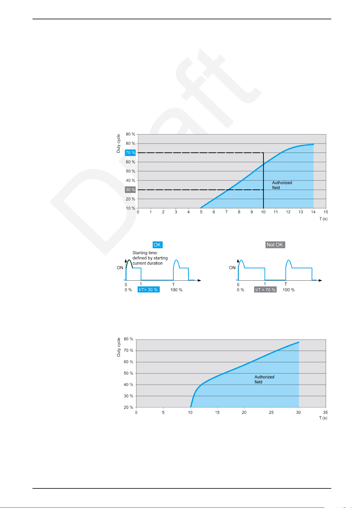
Due to the effect of the peak current on the TeSys H monitoring circuit during the
starting time, a stop/start sequence should not occur before a certain amount of
time. The diagrams below show the minimum duty cycle according to the total
period for two typical starting time values.
Starting time of 100 ms
Example for starting time of 100 ms with period T = 10 s.
Starting time of 150 ms
DOCA0111EN-03 47
Page 48

Page 49

Page 50

Schneider Electric
35 rue Joseph Monier
92500 Rueil Malmaison
France
+ 33 (0) 1 41 29 70 00
www.se.com
As standards, specifications, and design change from time to time, please ask for confirmation
of the information given in this publication.
© 2025 Schneider Electric. All rights reserved.
DOCA0111EN-03
 Loading...