

Page 1
Installation Guide Smart-UPS™On-Line SRT1000/SRT1500 XLA Tower/Rack-Mount
Important Safety Messages
Read the instructions carefully to become familiar with the equipment before attempting to install, operate, service or
maintain the UPS. The following special messages may appear throughout this manual or on the equipment to warn of
potential hazards or to call attention to information that clarifies or simplifies a procedure.
The addition of this symbol to a Danger or Warning product safety label indicates that an electrical hazard
exists which will result in personal injury if the instructions are not followed.
The addition of this symbol to a Warning or Caution product safety label indicates that a hazard exists that
can result in injury and product damage if the instructions are not followed.
Information
DANGER
DANGER indicates a hazardous situation which, if not avoided, will result in death or serious
injury.
WARNING
WARNING indicates a hazardous situation which, if not avoided, could result in death or serious
injury.
CAUTION
CAUTION indicates a hazardous situation which, if not avoided, could result in minor or moderate
injury.
NOTICE
NOTICE is used to address practices not related to physical injury.
Page 2

Safety and General Information
• Adhere to all national and local electrical codes.
• All wiring must be performed by a qualified electrician.
• Changes and modifications to this unit not expressly approved by APC could void the warranty.
• This UPS is intended for indoor use only.
• Do not operate this UPS in direct sunlight, in contact with fluids, or where there is excessive dust or
humidity.
• Be sure the air vents on the UPS are not blocked. Allow adequate space for proper ventilation.
• For a UPS with a factory installed power cord, connect the UPS power cable directly to a wall outlet. Do not
use surge protectors or extension cords.
• The equipment is heavy. Always practice safe lifting techniques adequate for the weight of the equipment.
• The batteries are heavy. Remove the batteries before installing the UPS and external battery packs (XLBPs),
in a rack.
• Always install XLBPs at the bottom in rack-mount configurations. The UPS must be installed above the
XLBPs.
• Always install peripheral equipment above the UPS in rack-mount configurations.
• Additional safety information can be found in the Safety Guide supplied with this unit.
Deenergizing safety
The UPS contains internal batteries and may present a shock hazard even when disconnected from the branch
circuit (mains).
• input circuit breaker is in the OFF position.
• internal UPS batteries are removed.
• XLBP battery modules are disconnected.
Before installing or servicing the equipment check that the:
Electrical safety
• For models with a hardwired input, the connection to the branch circuit (mains) must be performed by a
qualified electrician.
• The protective earth conductor for the UPS carries the leakage current from the load devices (computer
equipment). An insulated ground conductor is to be installed as part of the branch circuit that supplies the
UPS. The conductor must have the same size and insulation material as the grounded and ungrounded
branch circuit supply conductors. The conductor will typically be green and with or without a yellow stripe.
• The UPS input ground conductor must be properly bonded to protective earth at the service panel.
• If the UPS input power is supplied by a separately derived system, the ground conductor must be properly
bonded at the supply transformer or motor generator set.
Smart-UPS On-Line SRT1000/SRT1500 Tower/Rack-Mount 2U2
Page 3

Battery safety
• When replacing batteries, replace with the same number and type of batteries as originally installed in the
equipment.
• Batteries typically last for two to five years. Environmental factors impact battery life. Elevated ambient
temperatures, poor quality utility power, and frequent short duration discharges will shorten battery life.
Batteries should be replaced before end of life.
• Replace batteries immediately when the unit indicates battery replacement is necessary.
• Schneider Electric uses Maintenance-Free sealed Lead Acid batteries. Under normal use and handling, there
is no contact with the internal components of the battery. Over charging, over heating or other misuse of
batteries can result in a discharge of battery electrolyte. Released electrolyte is toxic and may be harmful to
the skin and eyes.
• CAUTION: Before installing or replacing the batteries, remove jewelry such as wristwatches and rings.
High short circuit current through conductive materials could cause severe burns.
• CAUTION: Do not dispose of batteries in a fire. The batteries may explode.
• CAUTION: Do not open or mutilate batteries. Released material is harmful to the skin and eyes and may be
toxic.
General information
• The UPS will recognize as many as 10 external battery packs connected to the UPS.
Note: For each XLBP added, increased recharge time will be required.
• The model and serial numbers are located on a small, rear panel label. For some models, an additional label
is located on the chassis under the front bezel.
• Always recycle used batteries.
• Recycle the package materials or save them for reuse.
FCC Class A radio frequency warning
This equipment has been tested and found to comply with the limits for a Class A digital device, pursuant to part 15
of the FCC Rules. These limits are intended to provide reasonable protection against harmful interference when the
equipment is operated in a commercial environment. This equipment generates, uses, and can radiate radio
frequency energy and, if not installed and used in accordance with the instruction manual, may cause harmful
interference to radio communications. Operation of this equipment in a residential area is likely to cause harmful
interference in which case the user will be required to correct the interference at his own expense.
3Smart-UPS On-Line SRT1000/SRT1500 Tower/Rack-Mount 2U
Page 4
Package Contents
x4
su04
x4
x6
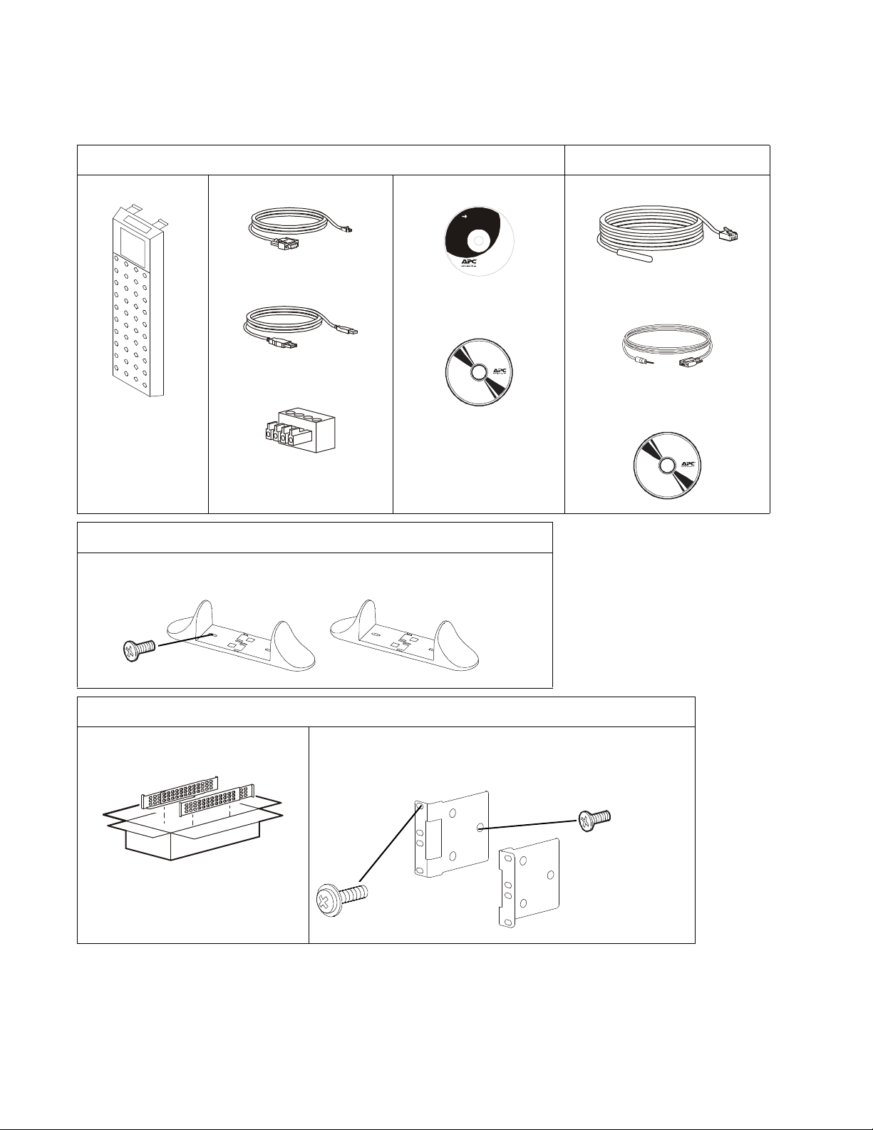
Inspect the contents upon receipt. Notify the carrier and dealer if the unit is damaged.
Included with all models NC models only
Front bezel RJ45 to DB9 cable
User Documentation CD.
USB cable
PCBE Software CD
EPO Terminal block
Included with Tower models only
• 2 pairs stabilizer brackets
• 4 flat head screws to secure tower stabilizer brackets to the UPS
Temperature sensor probe
User Do cumen tati on
Serial configuration cable
Network Management Utility CD
Included with Rack-Mount models only
Rail Kit with instructions and hardware
for installing rails in a rack.
34a
Smart-UPS On-Line SRT1000/SRT1500 Tower/Rack-Mount 2U4
• 1 pair rack-mount brackets
• 6 flat head screws to secure rack-mount brackets to the UPS
• 4 ornamental screws to secure rack-mount brackets to the rails
Page 5
Specifications
For additional specifications refer to the APC by Schneider Electric web site, www.apc.com.
Environmental
Temperature Operating 0º to 40º C (32º to 104º F)
Storage -15º to 45º C (5º to 113º F)
Elevation Operating 0 - 3,000 m (0 - 10,000 ft)
Storage 0 - 15,000 m (50,000 ft)
Humidity 0% to 95% relative humidity, non-condensing
Protection Class IP 20 rating
Note: Charge the battery modules every six months during storage.
Environmental factors impact battery life. Elevated ambient temperatures, high humidity, poor quality mains power, and
frequent short duration discharges will shorten battery life.
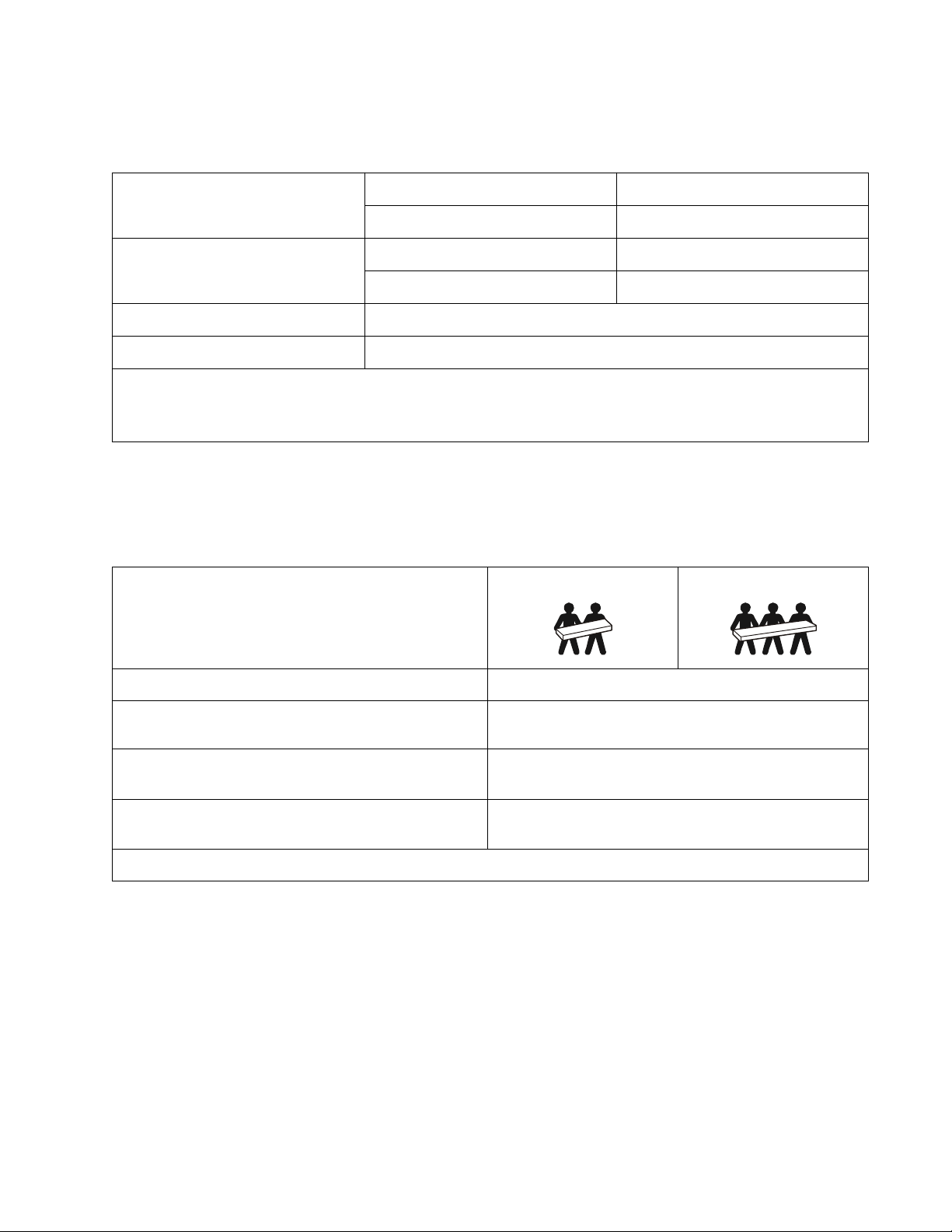
Physical
SRT1000XLA/SRT1000RMXLA/SRT1000RMXLA-NC
SRT1500XLA/SRT1500RMXLA/SRT1500RMXLA-NC model
The UPS is heavy. Follow all lifting guidelines.
Lifting guidelines 18 - 32 kg (40 - 70 lb) 32 - 55 kg (70 - 120 lb)
Unit weight batteries included, without packaging 22 kg (48.5 lb)
Unit weight batteries included, with packaging Rack-Mount models: 29.6 kg (65.26 lb)
Tower models: 26.9 kg (59.3 lb)
Unit dimensions without packaging
Height x Width x Depth
Unit dimensions with packaging
Height x Width x Depth
The model and serial numbers are on a small label located on the rear panel.
85 (2U) mm x 432 mm x 505 mm
3.35 (2U) in x 17 in x 20 in
245 mm x 595 mm x 750 mm
9.7 in x 23.4 in x 29.5 in
5Smart-UPS On-Line SRT1000/SRT1500 Tower/Rack-Mount 2U
Page 6

Battery
NOTICE
RISK OF EQUIPMENT DAMAGE
• Replace the battery at least every 5 years.
• Replace the battery immediately when the UPS indicates battery replacement is necessary.
Failure to follow these instructions can result in equipment damage
SRT1000/SRT1500 models
Battery type
Replacement battery module
This UPS has swappable battery modules.
Refer to the appropriate replacement battery user manual for installation
instructions.
Contact your dealer or go the APC by Schneider Electric web site,
www.apc.com for information on replacement batteries.
Number of battery modules 1 battery module
Voltage for each battery module 48 VDC
Total battery voltage for the UPS 48 VDC
Ah rating 9 Ah per battery module
XLBP cable length 500 mm (19.7 in)
Sealed, maintenance-free, Valve Regulated
Lead-Acid battery
APCRBC155
Smart-UPS On-Line SRT1000/SRT1500 Tower/Rack-Mount 2U6
Page 7
Electrical
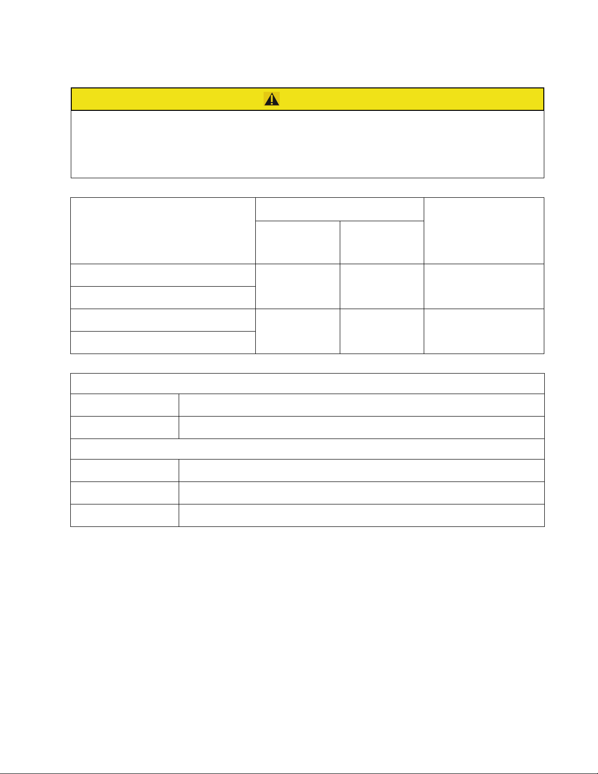
CAUTION
RISK OF FIRE, RISK OF ELECTRIC SHOCK
Connect the UPS models only to a circuit provided with recommended maximum branch circuit overcurrent protection in
accordance with the National Electrical Code, ANSI/NFPA 70 and the Canadian Electrical Code, Part I, C22.1.
Failure to follow these instructions can result in fire, and minor or moderate injury.
Models Rating Branch Circuit
Overcurrent Rating /
Online Green Mode
SRT1000XLA 1000 VA / 900 W 1000 VA 15 A
SRT1000RMXLA/SRT1000RMXLA NC
SRT1500XLA 1500 VA / 1350 W 1500 VA 15 A
Building Circuit
Breaker (CB) Current
Rating
SRT1500RMXLA/SRT1500RMXLA NC
Output
Output Frequency 50 Hz / 60 Hz (Selectable)
Nominal Output Voltage 120 V
Input
Input Frequency 40 Hz - 70 Hz
Nominal Input Voltage 120 V
Nominal Input Current 12 A
7Smart-UPS On-Line SRT1000/SRT1500 Tower/Rack-Mount 2U
Page 8
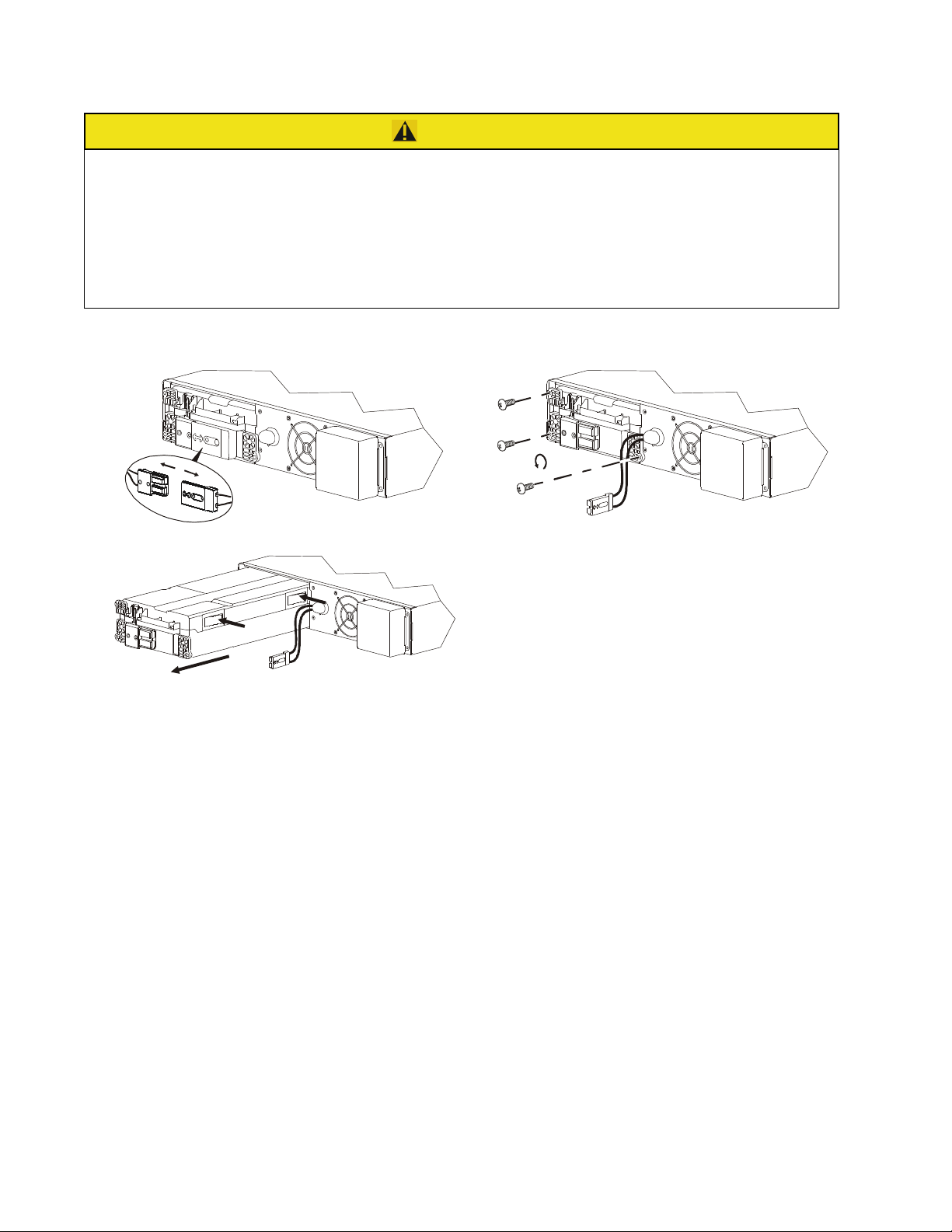
Remove Battery Module
x3
s
u
o
CAUTION
RISK OF FALLING EQUIPMENT
• The equipment is heavy. Each APCRBC155 battery module weighs 11 kg (24.25 lb).
• Always practice safe lifting techniques adequate for the weight of the equipment.
• Remove the battery modules before installing the UPS.
• Use the battery module handle to slide the battery modules in or out of the UPS.
• Do not use the battery module handle to lift or carry the battery module.
Failure to follow these instructions can result in minor or moderate injury.
a
8
9
1
1
o
u
s
a
0
0
2
1
o
u
s
a
9
9
1
1
Smart-UPS On-Line SRT1000/SRT1500 Tower/Rack-Mount 2U8
Page 9
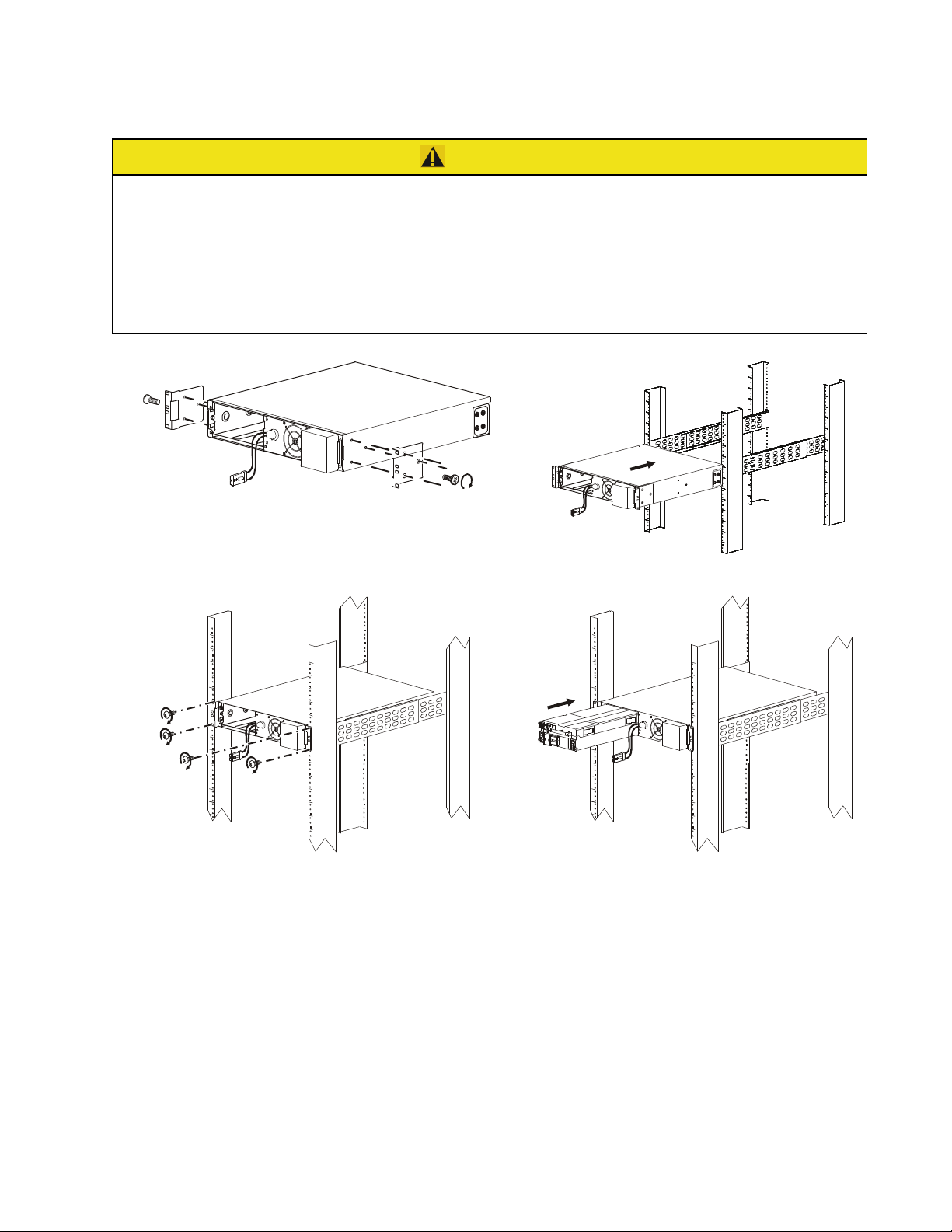
Rack-Mount Installation
x3
suo1202a
x4
suo1203a
suo1204a
Refer to the Rail Kit Installation Guide for instructions on rail installation.
CAUTION
RISK OF DAMAGE TO EQUIPMENT OR PERSONNEL
•
The equi
•
Al
pment is heavy. Always practice safe lifting techniques adequate for the weight of the equipment.
ways use the recommended number of screws to secure brackets to the UPS.
•Always use the recommended number of screws to secure the UPS to the rack.
•Always install the UPS at the bottom of the rack.
•Always install the XLBP below the UPS in the rack.
Failure to follow these instructions can result in equipment damage and minor or moderate injury
a
1
0
2
1
o
u
s
x3
9Smart-UPS On-Line SRT1000/SRT1500 Tower/Rack-Mount 2U
Page 10
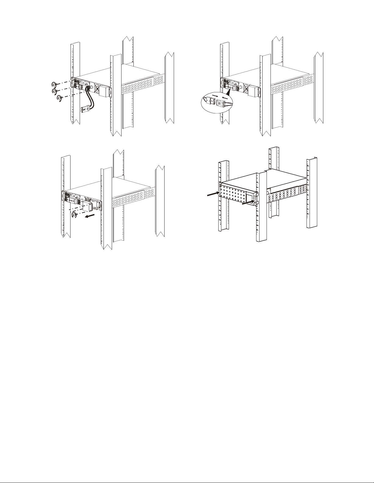
x3
suo1205a
suo1206a
x4
suo1207a
a
9
5
8
0
u
s
Smart-UPS On-Line SRT1000/SRT1500 Tower/Rack-Mount 2U10
Page 11
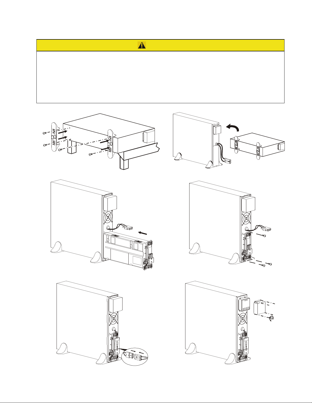
Tower Installation
CAUTION
RISK OF FALLING EQUIPMENT
• The equipment is heavy. Each APCRBC155 battery module weighs 11 kg (24.25 lb).
• Always practice safe lifting techniques adequate for the weight of the equipment.
• Remove the battery modules before installing the UPS.
• Use the battery module handle to slide the battery modules in or out of the UPS.
• Do not use the battery module handle to lift or carry the battery module.
Failure to follow these instructions can result in minor or moderate injury
c
5
4
8
0
u
s
c
1
7
8
0
o
u
s
suo1208a
suo1209a
x4
suo121 0a
suo1211a
11Smart-UPS On-Line SRT1000/SRT1500 Tower/Rack-Mount 2U
Page 12
GROUP 1
15 AMP Max
GROUP 1
15 AMP Max
suo0875c
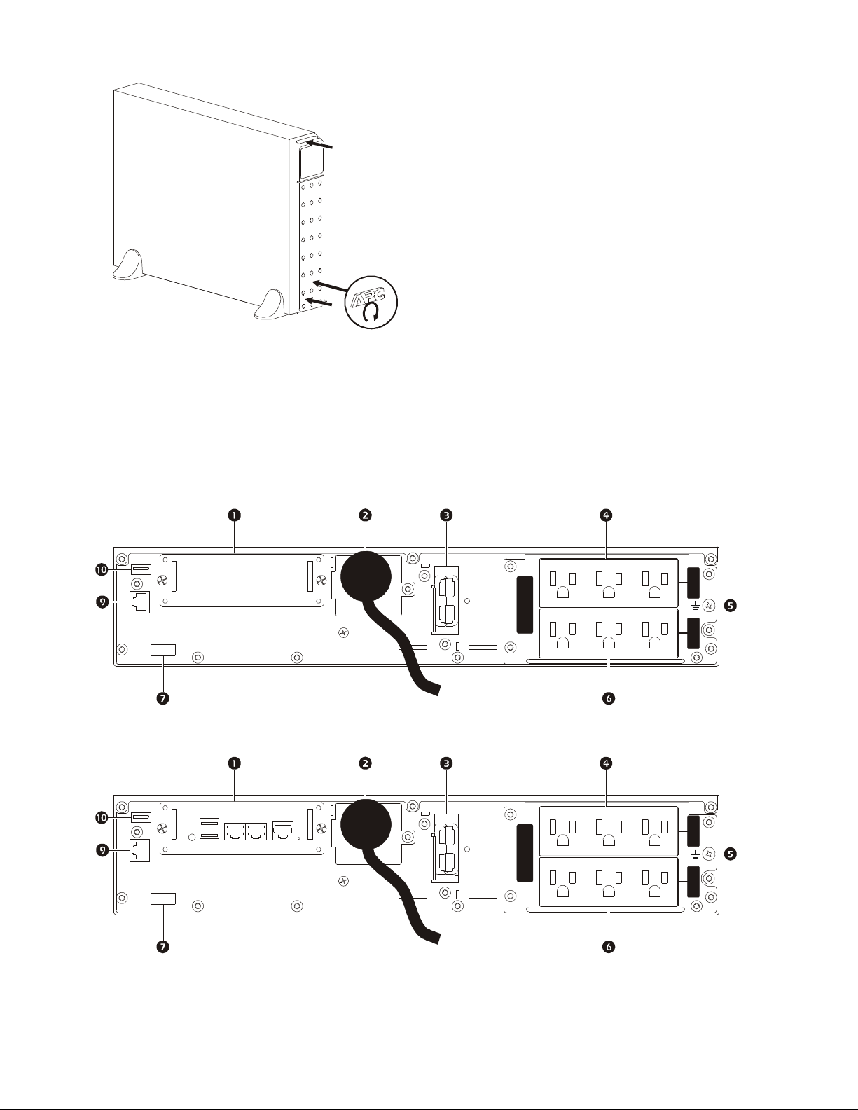
Rear Panel Features
Note: Refer to the table “Key to identify rear panel features” on page 13, that provides a key to the callout numbers
for the rear panel graphics depicted in this manual.
SRT1000XLA/SRT1000RMXLA
SRT1500XLA/SRT1500RMXLA
SRT1000RMXLA-NC/SRT1500RMXLA-NC
50/60 Hz
OUTPUT: 120 VAC
50/60 Hz
OUTPUT: 120 VAC
GROUP 2
15 AMP Max
suo1191b
GROUP 2
15 AMP Max
suo1192b
Smart-UPS On-Line SRT1000/SRT1500 Tower/Rack-Mount 2U12
Page 13

Key to identify rear panel features
SmartSlot The SmartSlot can be used to connect optional management accessories.
AC input power cable or
hardwire input box
External battery power and
communication connector
Controllable
outlet group 1
Chassis ground screw The UPS and XLBPs have ground screws for connecting the ground leads. Prior to
Controllable
outlet group 2
EPO terminal The Emergency Power Off (EPO) terminal allows the user to connect the UPS to a
Serial Com The Serial Com port is used to communicate with the UPS.
USB port The USB port is used to connect either a server for native operating system
All models have factory installed input power cables.
Hardwired input box is an optional accessory.
Use the external battery cable on the XLBP to connect the UPS and XLBP.
XLBPs provide extended runtime during power outages. The UPS will
automatically recognize up to 10 external battery packs.
Connect electronic devices to these outlets.
connecting a ground lead, disconnect the UPS from mains power.
Connect electronic devices to these outlets.
central EPO system.
Use only interface kits supplied or approved by APC by Schneider Electric.
Any other serial interface cable will be incompatible with the UPS connector.
communications, or for software to communicate with the UPS.
UPS Configuration
Connect Emergency Power Off feature
For instructions on how to connect the Emergency Power Off (EPO) switch, refer to the Operation and
Maintenance manual on the User Documentation CD (supplied).
Verify input connection
UPS displays Site Wiring Fault if the line and neutral connections are interchanged or if ground connection is
missing. Correct the input connections and press
UPS section in the UPS operation manual for details.
Configure controllable outlet groups
The outlets on the UPS are grouped. To configure the controlled outlet features, use the Advanced menus on the
display interface and navigate to: Main Menu > Configuration > Outlets > Outlet Group.
OK button to clear the Site Wiring Alert. See the Config Menu
13Smart-UPS On-Line SRT1000/SRT1500 Tower/Rack-Mount 2U
Page 14
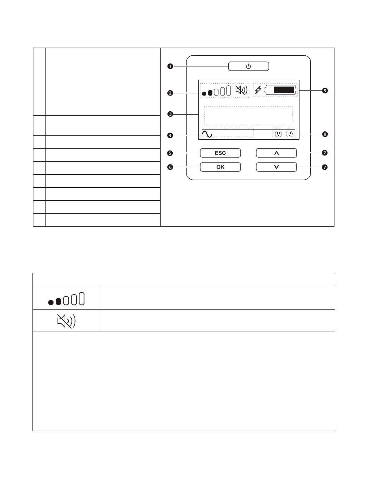
UPS Display Interface
su0870f
Output
120.0
v
LOAD
LOAD
POWER ON/OFF button
Button illumination indications:
-No illumination, the UPS and the output
power are off
-White illumination, the UPS and the outpu
ower are on
p
-Red illumination, the UPS is on and the
output power is off
Load icon
Disable/mute audible alarm icon
UPS status information
Operation mode icons
ESCAPE button
OK button
UP/DOWN buttons
Controllable outlet group status icons
t
On-Line
12
Battery status icons
Display interface operation
Use the UP/DOWN buttons to scroll through the options. Press the OK button to accept the selected option. Press
the
ESC button to return to the previous menu.
The icons on the LCD display interface screen may vary depending on the installed firmware version.
Load icon: The approximate load capacity percentage is indicated by the number of load bar
sections illuminated. Each bar represents 16% of the load capacity.
Mute icon: Indicates the audible alarm is disabled/mute.
UPS Status Information
The status information field provides key information on the status of the UPS.
The Standard menu will allow the user to select one of the five screens listed below. Use the
through the screens.
The Advanced menu will scroll through the five screens automatically.
• Input Voltage
• Output Voltage
• Output Frequency
•Load
• Runtime
UP/DOWN buttons to scroll
In the case of a UPS event, status updates will be displayed defining the event or condition that has occurred.
The display screen illuminates amber to indicate a Message and red to indicate an Alert depending on the severity of the
event or condition.
Smart-UPS On-Line SRT1000/SRT1500 Tower/Rack-Mount 2U14
Page 15
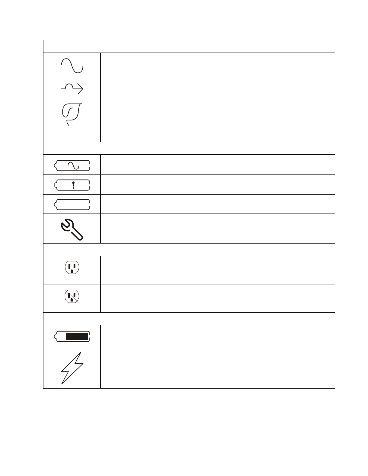
Operation Mode Icons
UPS Status Icon
On-Line mode: The UPS is supplying conditioned mains power to connected equipment.
Bypass mode: The UPS is in Bypass mode and the connected equipment will receive mains
power as long as the input voltage and frequency are within the configured limits.
Green mode: When in Green mode mains power is sent directly to the load.
In the event of a mains power outage, there will be an interruption in power to the load of up to
10 ms while the UPS switches to On-Line or Battery mode.
When enabling Green mode consideration should be given to devices that may be sensitive to
power fluctuations.
Battery mode: The UPS is supplying battery power to connected equipment.
The UPS has detected an internal fault with the battery. Follow the instructions on the screen.
X
The UPS has detected a critical fault with the battery. The battery is at the end of its life and has
to be replaced.
Indicates a UPS alert that requires attention.
Controllable Outlet Group Icons
Controllable Outlet Group Power Available: The number next to the icon identifies the
specific outlet groups that have available power.
Flashing icon indicates the outlet group is turning from OFF to ON with delay.
Controllable Outlet Group Power Not Available: The number next to the icon identifies
specific outlet groups that do not have available power.
Flashing icon indicates the outlet group is turning from ON to OFF with delay.
Battery Status Icons
Battery Charge Status: Indicates the battery charge status.
Battery Charge In Progress: Indicates the battery is charging.
15Smart-UPS On-Line SRT1000/SRT1500 Tower/Rack-Mount 2U
Page 16
Menu overview
The display interface has Standard and Advanced menu screens. The preference for Standard or Advanced menu
selections is made during initial installation and can be changed at any time through the Configuration menu.
The Standard menus include the most commonly used options.
The Advanced menus provide additional options.
Note: Actual menu screens may differ by model and firmware version.
Refer to the UPS Operation Manual for menu configuration details.
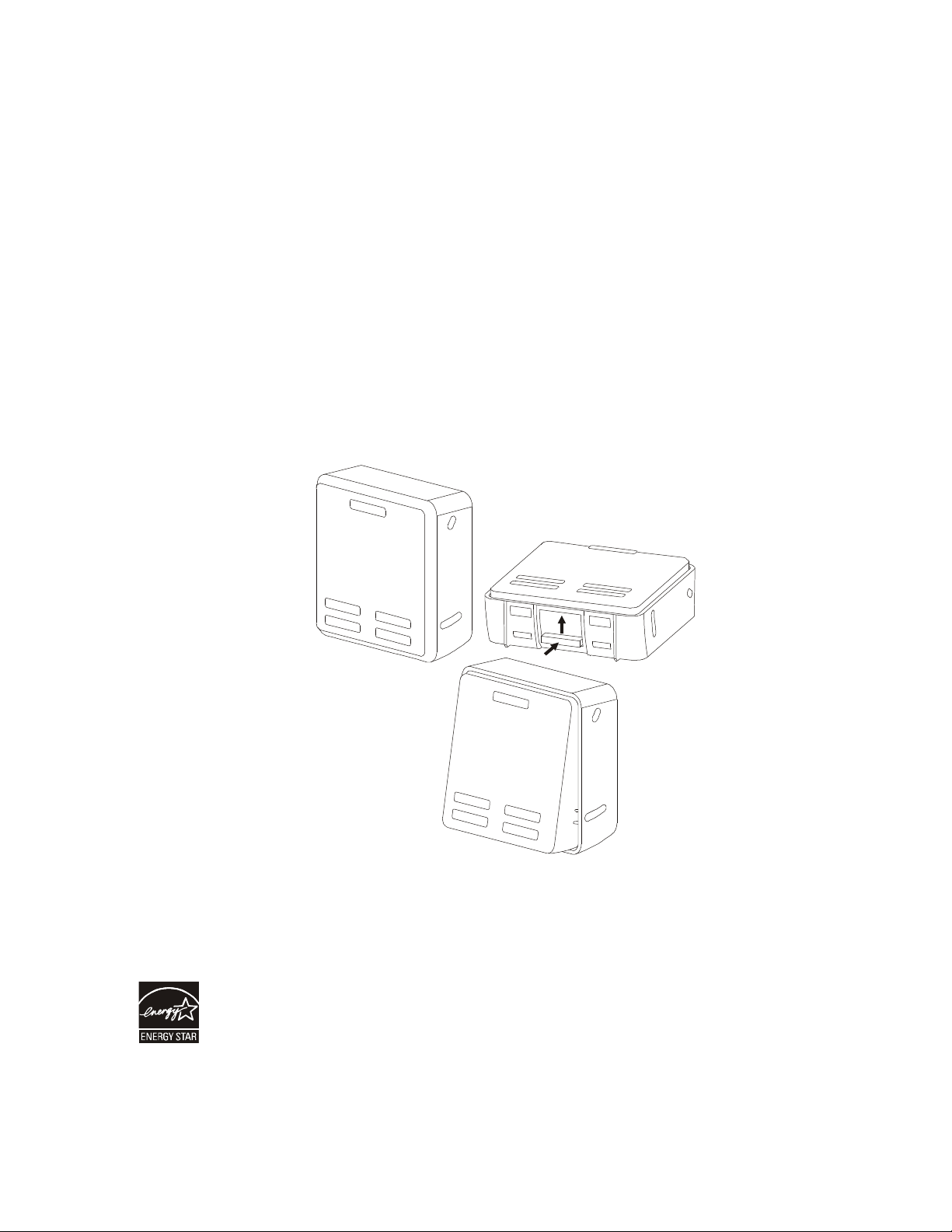
LCD display interface angle adjustment
The angle of the LCD display interface can be adjusted for ease in viewing the displayed messages.
1. Remove the front bezel.
2. Locate the button on the bottom of the display interface panel.
3. Press the button and slide the bottom of the LCD display interface screen out. An audible click will be heard
when the screen reaches the maximum angle.
a
6
2
9
0
u
s
Select models are ENERGY STAR® qualified
.
© 2016 APC by Schneider Electric. APC, the APC logo, and Smart-UPS are owned by Schneider
Electric Industries S.A.S. or their affiliated companies. All other trademarks are property of their
respective owners.
EN 990-5760A
11/20 16
 Loading...