

Page 1
Schaerer Mayfield USA, Inc.
7300
Modular Surgery
Table
Service and
Parts Manual
SMI
7300
SF-1586 Part No. 504-0023-00 Rev. E (5/04)
CA802000
FOR USE BY SMI
TRAINED TECHNICIANS
ONLY
Page 2

Page 3

TABLE OF CONTENTS
Section/Paragraph Page Section/Paragraph Page
IMPORTANT INSTRUCTIONS
General Safety Instructions........................................ iv
Warnings.................................................................... iv
Warranty Instructions ................................................. iv
SECTION I GENERAL INFORMATION
1.1 Scope of Manual ......................................... 1-1
1.2 How to Use Manual ..................................... 1-1
1.3 Description of 7300 Modular Surgery
Table ....................................................... 1-1
1.4 Specifications ............................................. 1-7
1.5 Parts Replacement Ordering ....................... 1-8
1.6 Special Tools .............................................. 1-9
SECTION II TESTING AND TROUBLESHOOTING
2.1 Operational Test.......................................... 2-1
2.2 Troubleshooting Procedures ........................ 2-6
SECTION III SCHEDULED MAINTENANCE
3.1 Scheduled Maintenance .............................. 3-1
SECTION IV MAINTENANCE/SERVICE
INSTRUCTIONS
4.1 Introduction ................................................. 4-1
4.2 Checking Oil Level / Adding Oil To
Reservoir .................................................. 4- 1
4.3 Calibration Of Return To Level / Neutral
Position .................................................... 4- 2
4.4 Hand Control Button Board
Removal / Installation ............................... 4-4
4.5 Hand Control Board
Removal / Installation ............................... 4-4
4.6 Seat Cylinders Synchronization
Procedure ................................................. 4- 5
4.7 Column Cylinder Slave Line Volume
Adjustment ............................................... 4- 7
4.8 Trendelenburg Cylinder
Removal / Installation ............................... 4-9
4.9 Trendelenburg Pilot Operated Check Valve
Removal / Installation ............................. 4-11
4.10 Trendelenburg Cylinder Orifice(s)
Removal / Installation ............................. 4-13
4.11 Trendelenburg Position Sensor
Removal / Installation ............................. 4-14
4.12 Lateral Tilt Cylinder
Removal / Installation ............................. 4-15
4.13 Lateral Tilt Orifice(s)
Removal / Installation ............................. 4-16
4.14 Lateral Tilt Pilot Operated Check Valve
Removal / Installation ............................. 4-18
4.15 Lateral Tilt Position Sensor
Removal / Installation ............................. 4-20
4.16 Seat Cylinder
Removal / Installation ............................. 4-21
4.17 Seat Cylinder Orifice(s)
Removal / Installation ............................. 4-26
4.18 Seat Cylinder Pilot Operated Check Valve
Removal / Installation ............................. 4-27
4.19 Seat Position Sensor
Removal / Installation ............................. 4-28
4.20 Column Cylinder
Removal / Installation ............................. 4-31
4.21 Column Pilot Operated Check Valve
Removal / Installation ............................. 4-34
4.22 Typical L.H. and R.H. Control Valve Solenoids
Removal / Installation ............................. 4-35
4.23 Typical Base Mounted Control Valve Solenoids
Removal / Installation ............................. 4-37
4.24 Discharge Filter Replacement .................... 4-39
4.25 Main Floor Lock or Outrigger
Floor Lock Cylinder
Removal / Installation ............................. 4-41
4.26 Motor Or Motor Pump
Removal / Installation ............................. 4-42
4.27 Pump Unit
Removal / Installation ............................. 4-44
4.28 Motor Pump Output Check Valve
Removal / Installation ............................. 4-47
4.29 Motor Pump Pressure Relief Valve
Removal / Installation ............................. 4-48
4.30 Outrigger Pressure Relief Valve
Removal / Installation ............................. 4-50
4.31 Main Controller Board
Removal / Installation ............................. 4-53
4.32 Charging / Power Driver Board
Removal / Installation ............................. 4-55
4.33 Emergency Override Panel
Removal / Installation ............................. 4-57
4.34 Distribution Board
Removal / Installation ............................. 4-58
4.35 RFI Filter
Removal / Installation ............................. 4-59
(*) Indicates that there has been a serial number break for the illustration
and that there are additional point page(s) following the original page.
© Schaerer Mayfield USA, Inc. 2004 Page iPrinted in U.S.A.
Page 4

TABLE OF CONTENTS - CONTINUED
Section/Paragraph Page Section/Paragraph Page
4.36 Transformer
Removal / Installation ............................. 4-61
4.37 Line Power Pilot Lamp
Removal / Installation ............................. 4-63
4.38 Plug Receptacle
Removal / Installation ............................. 4-63
4.39 Batteries
Removal / Installation ............................. 4-64
4.40 Primary Thermostat
Removal / Installation ............................. 4-65
4.41 Secondary Thermostat
Removal / Installation ............................. 4-66
4.42 Floor Lock Status Switch
Removal / Installation ............................. 4-66
4.43 Head Section Gas Spring
Removal / Installation / Adjustment ........ 4-68
4.44 Foot Control Interface Board
Removal / Installation ............................. 4-69
4.45 Typical Latch Mechanism
Removal / Installation ............................. 4-70
4.46 Typical Floor Lock Check Valve
Removal / Installation ............................. 4-71
4.47 Articulating Leg Transfer Board
Adjustments............................................ 4-73
4.48 Bell Footpiece Traction Crank Assembly
Disassembly / Assembly ........................ 4-75
SECTION V SCHEMATICS AND DIAGRAMS
5.1 Electrical Schematics / Wiring Diagrams..... 5-1
5.2 Hydraulic Flow Diagram................................ 5-4
5.3 Hand Control Messages ............................... 5- 5
5.4 Error Code Chart .......................................... 5- 6
SECTION VI PARTS LIST
6.1 Introduction ................................................. 6-1
6.2 Description of Columns ............................... 6-1
6.3 Torque Specifications And Important
Assembly Notes ....................................... 6-1
Pictorial Index ............................................. 6-2
Accessories ................................................. 6- 3
Labels And Decals ....................................... 6-4
Cushions and Table Tops............................. 6- 5
Covers and Shields ...................................... 6-6
Head Section Assembly............................... 6-7
Bridge Components...................................... 6-8
Lateral Tilt Cylinder Assembly...................... 6- 9
Upper Hose Connections............................ 6-10
L.H. Side Components ............................... 6-11
L.H. Control Valve Assembly ..................... 6-12
L.H. Seat Cylinder Assembly ..................... 6-13
R.H. Side Components............................... 6-14
Emergency Override Panel Assembly ........ 6-15
R.H. Control Valve Assembly..................... 6-16
R.H. Seat Cylinder Assembly..................... 6-17
Column Assembly Components ................. 6-18
Column Assembly ...................................... 6-19
Trendelenburg Cylinder Assembly ............. 6-20
Column Cylinder Assembly ........................ 6-21
Hand Control Assembly.............................. 6-22
Base Cover Components ........................... 6-23
Base Hydraulic / Electrical
Components............................................ 6-24
Electrical Control Box Components ............ 6-25
Base Hydraulic Plumbing ........................... 6-26
Base Control Valve Assembly.................... 6-27
Hydraulic Pump / Motor Components ......... 6-28
Hydraulic Motor Components ..................... 6-29
Hydraulic Pump Components ..................... 6-30
Floor Lock Components ............................. 6-31
Main Floor Lock Cylinder Components ....... 6-32
Outrigger Floor Lock Cylinder
Components............................................ 6-33
Caster Components ................................... 6-34
Power Driver Board Components................ 6-35
Battery Components .................................. 6-36
10210 Perineal Post Assembly .................. 6-37
10322 Cross Arm Support Assembly ......... 6-38
10360 Safety Strap .................................... 6-39
10395 Lottes Anklet ................................... 6-40
10508 Well Leg Support Assembly............. 6-41
10509 Equipment Cart................................ 6-42
10620 Drape Stand Assembly .................... 6-43
10821 Removable Siderail.......................... 6-44
10823 Leg Transfer Board .......................... 6-45
10824 Horizontal Perneal Post ................... 6-46
10825 Tibia Extender ................................. 6-47
10830 Well Leg Support (Siderail Mount).... 6-48
10836 Offset Adapter Mount ...................... 6-49
13100 / 13200 Montreal Lateral
Position Device....................................... 6-50
(*) Indicates that there has been a serial number break for the illustration
and that there are additional point page(s) following the original page.
© Schaerer Mayfield USA, Inc. 2004
Page iiPrinted in U.S.A.
Page 5

TABLE OF CONTENTS - CONTINUED
Section/Paragraph PageSection/Paragraph Page
22111 Pin and Wire Holder ......................... 6-51
22119 Traction Bow Assembly ................... 6-52
22314 Traction Cuff Assembly ................... 6-53
70542 Bierhoff Leg Holder .......................... 6-54
70556 Siderail Extension Set ..................... 6-55
71070 Siderail Socket ................................ 6-56
71071 I.V. Arm Board Assembly ................ 6-57
71073 Siderail Clamp ................................. 6-58
71074 Conventional Ether Screen .............. 6-59
71075 Foot Rest......................................... 6-60
71077 Siderail Extender Set ....................... 6-61
71078 A/P Cassette Holder ........................ 6-62
71079 Lithotomy Leg Holder ....................... 6-63
71080 Universal Ether Screen .................... 6-64
71082 Lateral Cassette Holder ................... 6-65
71083 Cross Arm Support .......................... 6-66
71084 / 71085 / 71093 I.V. Arm Board
Cushion .................................................. 6-67
71088 Neuro Headrest Adapter................... 6-68
71090 Lateral Support Set.......................... 6-69
71092 Infant Arm & Hand Table ................. 6-70
71094 Table Side Extenders ...................... 6-71
71097 Tri Clamp 2 ...................................... 6-72
71098 Flexguard Stirrup Set ....................... 6-73
71099 Guardian Stirrup Set ........................ 6-74
71100 Leg Prep Stand................................ 6-75
71101 Snaplock Arm Board........................ 6-76
71102 / 71103 Snaplock Arm
Board Cushion ........................................ 6-77
71104 Shoulder Brace Set.......................... 6-78
71105 Universal Patient Brace /
71113 Circular Head Cushion ..................... 6-79
71106 / 71107 Uro Catch Bags................... 6-80
71108 Winged Anesthesia Screen.............. 6-81
71110 Footswitch ....................................... 6-82
71111 Split Leg Set - 71118 / 71119 Split
Leg Pad Set............................................ 6-83
71112 Foot Extension Assembly /
71114 Foot Extension Cushion................... 6-84
71116 Conductive Safety Strap /
20715 Nonconductive Safety Strap ............ 6-85
71120 Side Extender Shelf......................... 6-86
71125 Image Amplification Extension ....... 6-87
71129 X-Ray Arm Board............................. 6-88
71130 I.A. Board (36-inch).......................... 6-89
73001 Pelvic Base w/ Cushion ................... 6-90
73002 Leg Transfer Board w/ Cushion ........ 6-91
73003 Drain Pan......................................... 6-92
73004 I.A. Extention w/ Cushion (55-inch).. 6-93
73005 X-Ray Top Set................................. 6-94
73006 Back Section ................................... 6-95
73007 Ortho Pelvic Base /
73023 / 73024 Board w/ Cushion............ 6-96
73008 Abductor Bar ................................... 6-97
73009 Abductor Bar Clamp ........................ 6-98
73010 Traction Unit .................................... 6-99
73011 Traction Unit Extention .................. 6-100
73012 Popliteal Support ........................... 6-101
73013 Lateral Well Leg Holder .................. 6-102
73014 Shoulder Arthroscopic Attachment. 6-103
Shoulder Arthroscopic Lumbar
Support Assembly ................................ 6-104
Shoulder Arthroscopic Head Rest............. 6-105
73015 Articulating Bracket ....................... 6-106
73016 Drapery Kit .................................... 6-107
73019 Back Section X-Ray Top ............... 6-108
73020 Leg Transfer Frame ....................... 6-109
73021 Yellofin Leg Holder System.... Not Shown
73022 Clear Vision Drapes ............... Not Shown
10531 Bell Footpiece Traction Assy......... 6-110
73025 Orthopedic Cart ............................. 6-111
73026 General Surgery Cart ..................... 6-112
COMMENTS ............................................................ 7-1
(*) Indicates that there has been a serial number break for the illustration
and that there are additional point page(s) following the original page.
Page iiiPrinted in U.S.A.© Schaerer Mayfield USA, Inc. 2004
Page 6
IMPORTANT INSTRUCTIONS
General Safety Instructions
Safety First: The primary concern of
Schaerer Mayfield USA is that this surgery table is
maintained with the safety of the patient and staff in
mind. Toassure that services and repairs are completed
safely and correctly, proceed as follows:
(1 ) Read this entire manual before performing any
services or repairs on this surgery table.
(2 ) Be sure you understand the instructions con-
tained in this manual before attempting to
service or repair this surgery table.
Warnings
Throughout this manual are Note, Caution, and Danger
paragraphs that call attention to particular procedures.
These items are used as follows:
NOTE
A note is used to amplify an operating procedure,
practice or condition.
Warranty Instructions
Refer to the SMI “Limited Warranty” printed on the
back cover of the Installation and Operation Manual for
warranty information. Failure to follow the guidelines
listed below will void the warranty and / or render the
7300 Modular Surgery Table unsafe for operation.
• In the event of a malfunction, do not attempt to
operate the surgery table until necessary repairs have
been made.
• Do not attempt to disassemble surgery table, replace
malfunctioning or damaged components, or perform
adjustments unless you are one of SMI’s
authorized service technicians.
• Do not substitute parts of another manufacturer when
replacing inoperative or damaged components. Use
only SMI replacement parts.
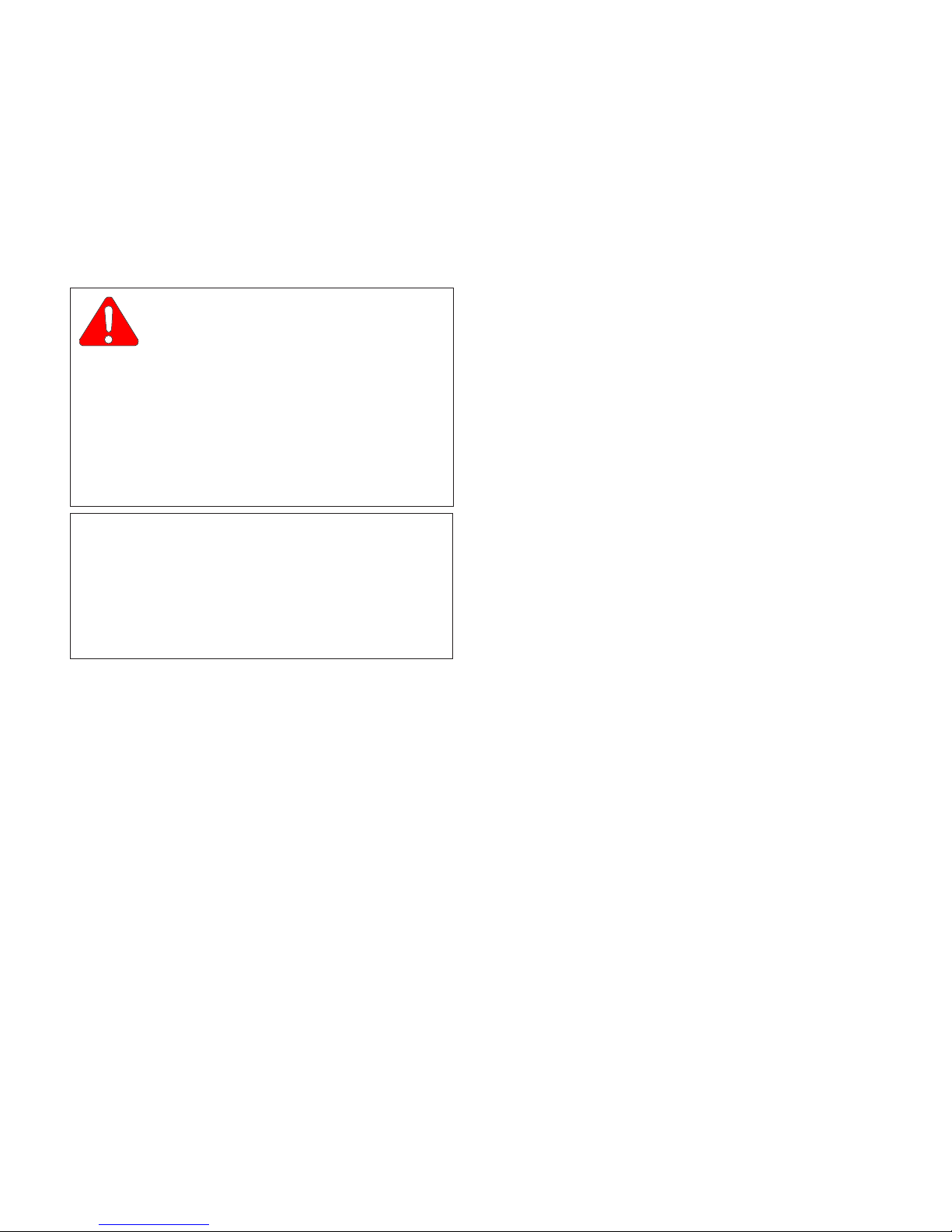
CAUTION
A CAUTION is used for an operating
procedure, practice, or condition which, if
not correctly followed, could result in equipment
damage.
DANGER
A DANGER is used for an operating
procedure, practice, or condition
which, if not correctly followed, could result in
loss of life or serious personal injury.
© Schaerer Mayfield USA, Inc. 2004
Page ivPrinted in U.S.A.
Page 7

SECTION I
GENERAL INFORMATION
SECTION I
GENERAL INFORMATION
1.1 Scope of Manual
This manual contains detailed troubleshooting, scheduled maintenance, maintenance, and service instructions for 7300 Modular Surgery Table. This manual is
intended to be used by SMI’s authorized service
technicians.
1.2 How to Use Manual
A. Manual Use When Performing Scheduled Mainte-
nance.
(1) Perform inspections and services listed in
Scheduled Maintenance Chart (Refer to
para 3.1).
(2) If a component is discovered to be faulty or out
of adjustment, replace or adjust component in
accordance with maintenance/service instructions (Refer to para 4.1).
B. Manual Use When Unit Is Malfunctioning And
Cause Is Unknown.
(1) Perform an operational test on unit (Refer to
para 2.1).
(2) Perform troubleshooting procedures listed in
Troubleshooting Guide (Refer to para 2.2).
(3) If a component is discovered to be faulty or out
of adjustment, replace or adjust component in
accordance with maintenance/service instructions (Refer to para 4.1).
C. Manual Use When Damaged Component Is Known.
(1) Replace or adjust component in accordance
with maintenance/service instructions (Refer to
para 4.1).
1.3 Description Of 7300 Modular Surgery
Table
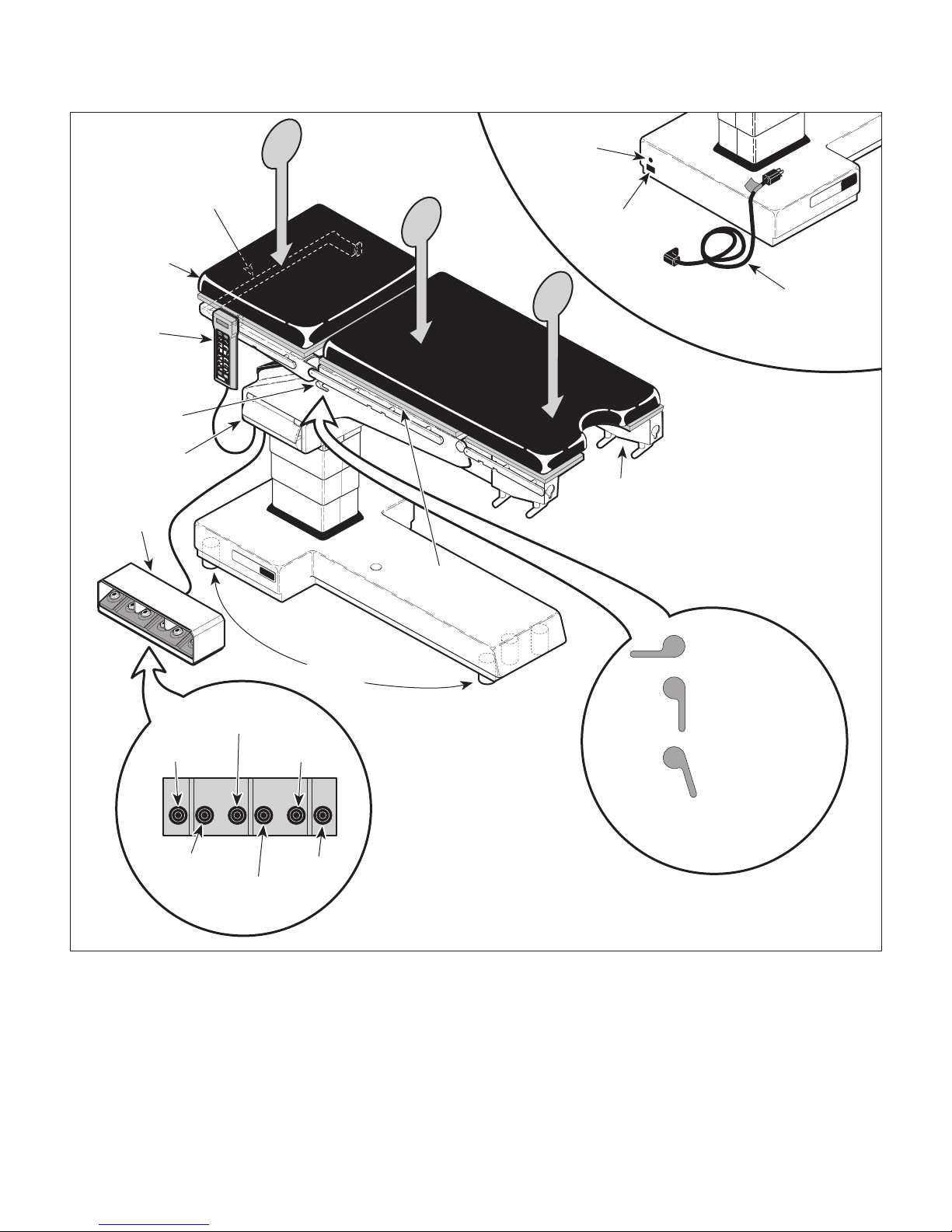
A. General Description (See Figure 1-1, Sheets 1
and 2).
The 7300 Modular Surgery Table is designed for use as
a general surgery table on which virtually any surgical
procedure can be accomplished. 7300 was designed
for maximum C-arm access and X-ray visibility.
Major serviceable components of the surgery table are:
1. Motor pump which includes two motors, two pump
units, two motor pump pressure relief valves, two
primary thermostats, two secondary thermostats, and a
motor pump output check valve, and a discharge filter,
2. Trendelenburg (UP and DOWN) solenoid valves,
Trendelenburg cylinder pilot operated check valves,
and Trendelenburg cylinder, trendelenburg position
sensor.
3. Seat (UP and DOWN) solenoid valves, seat cylinder
pilot operated check valves, seat cylinders and, seat
position sensor.
4. Lateral tilt (LEFT and RIGHT) solenoid valves,
lateral tilt cylinder pilot operated check valves, lateral tilt
cylinder, and lateral tilt position sensor.
5. Column (UP and DOWN) solenoid valves, column
cylinder pilot operated check valve, column cylinder,
and column assembly which includes slides.
6. Main and Outrigger Floor Lock solenoid valves,
three main floor lock cylinders, two outrigger floor lock
cylinders, outrigger pressure relief valve, main and
outrigger floor lock status switches.
7. Head section with two gas cylinders.
8. Main Controller Board which includes a 10 amp
fuse.
9. Charging / Power Driver Board which includes a 40
amp fuse.
10. RFI filter.
11. Transformer.
12. Four batteries.
13. Hand control which includes button board and
hand control board.
14. Foot control which includes foot switch pad and
foot control interface board.
15. Emergency override board.
16. Distribution board.
17. Plug Receptacle which includes two 5 amp fuses,
and line power pilot lamp.
© Schaerer Mayfield USA, Inc. 2004
Page 1-1Printed in U.S.A.
Page 8
SECTION I
GENERAL INFORMATION
Figure 1-1. Major Components (Sheet 1 of 2)
Page 1-2Printed in U.S.A.© Schaerer Mayfield USA, Inc. 2004
Page 9
SECTION I
GENERAL INFORMATION
Figure 1-1. Major Components (Sheet 2 of 2)
Page 1-3Printed in U.S.A.© Schaerer Mayfield USA, Inc. 2004
Page 10
SECTION I
GENERAL INFORMATION
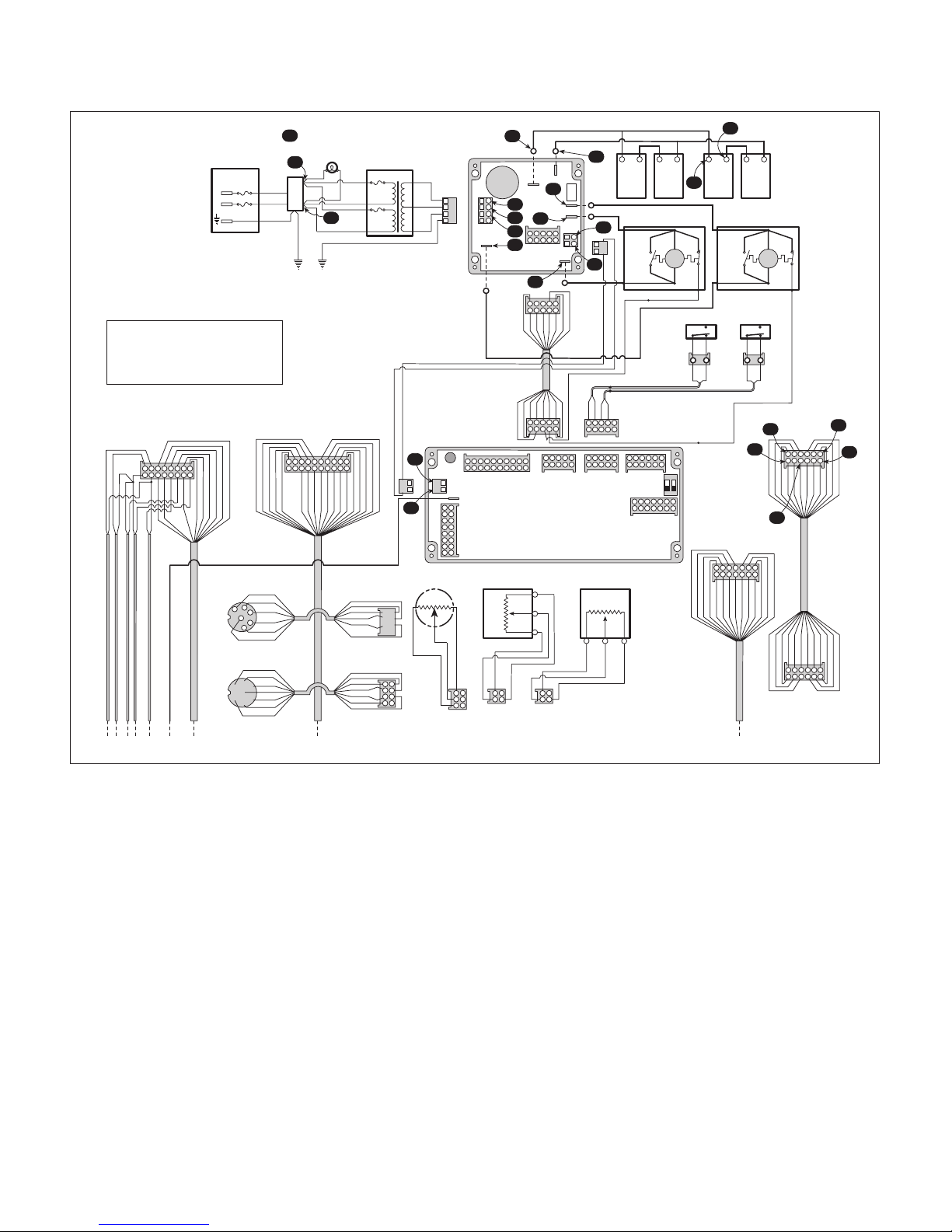
B. Theory of Operation. See Figures 5-1, Sheets 1
and 2, and Figure 5-2 for electrical schematic /
wiring diagram. See Figure 5-3 for hydraulic
schematic.
Electrical Theory Of Operation
When power cord is plugged into power cord receptacle, line voltage (approximately 115 VAC) is supplied
to table. Line voltage is applied across an RFI filter.
RFI filter reduces line conducted RFI / EMI that is
present on incoming power line. Across RFI filter
output is a line power pilot lamp which illuminates to
indicate power is present at output of RFI filter.
Transformer primary lines are also connected across
RFI filter output. Transformer steps line voltage down
to 32.5 VAC ± 2 VAC. The 32.5 VAC from output of
transformer is applied to charging / power driver board.
Charging / power driver board uses a DC rectifying
circuit to convert 32.5 VAC to approximately 27.8 VDC.
Charging / power driver board regulates charging rate
of four batteries by regulating rate at which 27.8 VDC is
applied to batteries. Charging / power driver board also
supplies 27.5 VDC to main controller board to power it.
Transformer has thermal fuses connected in each
primary winding and they are embedded between the
primary and secondary windings. If transformer overheats, normally closed (N.C.) thermal fuses open,
disconnecting power to transformer.
Transformer is primarily used to supply power to
charging / power driver board, so board can charge
batteries and supply power to rest of table.
Charging / power driver board regulates charge rate
of batteries when batteries are being charged. This
means that a full load is not continuously being placed
on transformer, which is important because transformer
is not sized to draw a full current load continuously. If
batteries are low and a function is selected, power to
drive motor pump(s) is drawn from batteries first and
then from transformer as necessary. If batteries are too
low or a function is selected for too long, continuous
current draw thru transformer will overheat transformer
very quickly, causing thermal fuses to blow.
CAUTION
It is important that a table with a low battery charge be operated only in case of
emergency and for a very short time period (less
than a minute).
Logic Theory Of Operation
When ENABLE button is pressed, a 5 VDC signal is
sent to main controller board, activating it. Main
controller board performs a self diagnostic check on
itself. If self diagnostic check fails, error code E11
(Internal RAM / Register Failure) is displayed on hand
control.
Main controller board and charging / power driver board
uses status circuits to check functionality of following
electrical components: motors, charging / power driver
board, valve spool solenoids, main controller board,
position sensors, foot control switch pad, and hand
control button board.
A status circuit, on charging / power driver board,
monitors amount of current draw thru motor pump
windings, when a function has been selected. If current
draw exceeds a predetermined value, main controller
board stops all functions and displays error code E02
(Overcurrent - Motor Pump #1) or E03 (Overcurrent Motor Pump #2), which indicates a failure of a motor
pump.
If current draw falls below a predetermined value, main
controller board stops all functions and displays error
code E04, which indicates failure of charging / power
driver board.
A status circuit, on main controller board, monitors
enable circuitry for each valve spool solenoid and
detects if a valve spool solenoid or enable circuitry of
main controller board is functioning correctly. If not,
main controller board stops all functions and displays
error code E05 (Valve Drive Failure), which indicates
failure of either a valve spool solenoid or main controller
board.
Another status circuit, on main controller board, monitors voltage input from position sensors. If voltage
value exceeds or falls below a predetermined range,
main controller board stops all functions and displays
appropriate error code: E07 (Trendelenburg Position
Sensor Failure), E08 (Tilt Position Sensor Failure), E09
(Seat Position Sensor Failure). An error code indicates
failure of either a position sensor, main controller board,
or wiring.
Main controller board also monitors main floor lock
status switch, outrigger floor lock status switch, motor
pump #1 primary thermostat, and motor pump # 2
primary thermostat. When hand control is ENABLED,
main controller board checks if normally open (N.C.)
main floor lock status switch and outrigger floor lock
status switch is untripped. If main controller does not
detect that
energizes main floor lock valve spool and motor pump,
causing main floor locks to extend. After eight seconds,
main controller de-energizes main floor lock valve spool
both
status switches are untripped, it
Page 1-4Printed in U.S.A.© Schaerer Mayfield USA, Inc. 2004
Page 11

SECTION I
GENERAL INFORMATION
and motor pump, and then energizes outrigger floor
lock valve spool and motor pump, causing outrigger
floor locks to extend. After six seconds, main controller
de-energizes outrigger floor lock valve spool and motor
pump. At this time main controller checks status of
status switches again. If main controller does not
detect that
all functions and displays E01 (Floor Lock Status
Switch Is Not Responding).
Also, when hand control is ENABLED, main controller
board checks if normally closed (N.C.) motor pump
primary thermostats are closed. If main controller
board detects an open circuit, it stops all functions and
displays error code E13 (Overheat - Motor Pump #1) or
E14 (Overheat - Motor Pump #2), which indicates that
motor pump has overheated, opening its primary
thermostat.
Also, when hand control is ENABLED, main controller
board checks status of each set of switches in hand
control; there are two normally open (N.O.) switches for
each function, one for solenoid valve and one for motor.
If only one of the set of two switches is detected as
being pressed, main controller board detects this and
displays error code E15 (Hand Control Switch Failure).
This indicates that one switch is stuck in closed position. Also, if a function button is pressed and then error
code E15 displays, this indicates that only one of two
switches is working properly. This safety feature
prevents unintended table movement due to a switch
malfunction.
Also, when a function is selected using foot control,
main controller board checks status of each set of
switches in the foot control pad; there are two normally
open (N.O.) switches for each function. If there is a set
of switches for which only one of two switches is
detected as being pressed, the main controller board
detects this and displays error code E06 (Foot Switch
Failure) on hand control. This indicates that one of two
switches is stuck in closed position or not working
properly. This safety feature prevents unintended table
movement due to a switch malfunction.
Motor pumps also have secondary thermostats which
provide backup protection if primary thermostats fail. If
a motor pump overheats and its primary thermostat
does not shut off motor pump, normally open (N.O.)
secondary thermostat closes, directly shorting current
past motor windings to ground, causing 40 amp fuse on
charging / power driver board to blow, which stops
motor pump.
both
status switches are untripped, it stops
Hydraulic System Theory Of Operation
When a function is selected using hand control or foot
control, motor pump(s) begins to run and selected
function's valve spool shifts.
Hydraulic oil flows thru a strainer in reservoir and into
pump chamber. Pump pumps oil thru an internal check
valve, and a discharge filter. Oil is now in supply line,
ready to power selected function's cylinder(s). Motor
pump internal check valve allows oil to flow thru to the
supply line, but closes when motor pump stops running,
preventing oil from back flowing into motor pump, which
prevents gravity drain out of supply line and back into
motor pump. Discharge filter removes any contaminants from oil before oil reaches any hydraulic components. This prevents reduced life expectancy of
hydraulic components such as seals and o-rings and
prevents clogging of valves and check valves.
There is a 250 BAR (3625 PSI) pressure relief valve on
each motor pump. If pressure reaches or exceeds this
pressure, valve opens dumping oil back into reservoir.
Oil is now in supply line, ready to power selected
function's cylinder(s).
Trendelenburg and Lateral Tilt
If
Trendelenburg
control was selected (in normal table orientation), motor
pump is energized and valve spool for that function
moves to an up function position (oil will now flow in
new oil flow path that has been created; this path is
shown by straight flow symbols on hydraulic schematic)
and oil flows thru a check valve (A) and into the base of
cylinder, extending cylinder. Check valve (A) prevents
oil from escaping from cylinder after valve spool is deenergized, keeping cylinder from drifting. Oil also flows
thru a pilot line (represented by a dashed line on
hydraulic schematic) and extends a pilot piston. Pilot
piston forces open check valve (B) on retracting side of
cylinder, allowing oil to escape from top side of cylinder, thru valve spool and into the oil return line.
If
Reverse Trendelenburg
hand control was selected (in normal table orientation),
motor pump is energized and valve spool for that
function moves to a down function position (oil will now
flow in new oil flow path that has been created; this path
is shown by crossed flow symbols on the hydraulic
schematic) and oil flows thru a check valve (B) and into
top of cylinder, retracting cylinder. Check valve (B)
prevents oil from escaping from cylinder after valve
spool is de-energized, keeping cylinder from drifting.
Oil also flows thru a pilot line (represented by a dashed
line on hydraulic schematic) and extends a pilot piston.
or
Lateral Tilt Left
or
button on hand
Lateral Tilt Right
button on
Page 1-5Printed in U.S.A.© Schaerer Mayfield USA, Inc. 2004
Page 12

SECTION I
GENERAL INFORMATION
Pilot piston forces open check valve (A) on base of
cylinder, allowing oil to flow from base of cylinder, thru
valve spool, and into oil return line.
Seat Functions
If
SEAT UP
normal table orientation), motor pump is energized and
valve spool for that function moves to an up function
position (oil will now flow in new oil flow path that has
been created; this path is shown by straight flow
symbols on hydraulic schematic) and oil flows thru a
check valve (A) and into base of left cylinder (master
cylinder), extending cylinder. Check valve (A) prevents
oil from escaping from cylinder after valve spool is deenergized, keeping cylinder from drifting. Oil also flows
thru two pilot lines (represented by dashed lines on
hydraulic schematic) and extends two pilot pistons (B
and D). One pilot piston forces open a check valve (B)
which allows oil to flow out of top side of left cylinder
thru another check valve (C) and into base of right
cylinder (slave cylinder), extending cylinder. Other pilot
piston forces open check valve (D) on top side of right
cylinder (slave cylinder), allowing oil to flow from top
side of cylinder, flow thru valve spool and into oil return
line.
If
SEAT DOWN
normal table orientation), motor pump is energized and
valve spool for that function moves to a down function
position (oil will now flow in new oil flow path that has
been created; this path is shown by crossed flow
symbols on hydraulic schematic) and oil flows thru a
check valve (D) and into top of right cylinder (slave
cylinder), retracting cylinder. Check valve (D) prevents
oil from escaping from right cylinder after valve spool is
de-energized, keeping cylinder from drifting. Oil also
flows thru two pilot lines (represented by dashed lines
on hydraulic schematic) and extends two pilot pistons.
One pilot piston forces open a check valve (C) which
allows oil to flow out of base of right cylinder thru
another check valve (B) and into top side of left cylinder
(master cylinder), retracting cylinder. Other pilot piston
forces open check valve (A) on base of left cylinder
(master cylinder), allowing oil to flow out of base of
cylinder, thru valve spool, and into oil return line.
Column Functions
If
TABLE UP
pump energizes and valve spool for that function moves
to an up function position (oil will now flow in new oil
flow path that has been created; this path is shown by
straight flow symbols on hydraulic schematic) and oil
flows thru a check valve (A) and into base of column
button on hand control is selected (in
button on hand control is selected (in
button on hand control is selected, motor
cylinder, extending cylinder. Check valve (A) prevents
oil from escaping from column cylinder after valve spool
is de-energized, keeping cylinder from drifting. Oil flows
out of top side of column cylinder as necessary, thru
valve spool, and into return line.
If
TABLE DOWN
motor pump energizes and valve spool for that function
moves to a down function position (oil will now flow in
new oil flow path that has been created; this path is
shown by crossed flow symbols on hydraulic schematic) and oil flows to top side of base cylinder, retracting cylinder. Oil also flows thru a pilot line (represented
by a dashed line on hydraulic schematic) and extends a
pilot piston. Pilot piston forces open check valve (A) on
base of cylinder, allowing oil to flow out of base of
cylinder, thru valve spool, and into oil return line.
Floor Lock Functions
If
ENABLE / LOCK
motor pump energizes and valve spool for main floor
lock cylinders moves to an up function position (oil will
now flow in new oil flow path that has been created; this
path is shown by straight flow symbols on hydraulic
schematic) and oil flows thru a check valve (A) and into
base of three main floor lock cylinders, extending
cylinders. Check valve (A) prevents oil from escaping
from three main floor lock cylinders after valve spool is
de-energized, keeping cylinders from drifting.
After approximately 10 seconds, main controller board
de-energizes motor pump and main floor lock spool and
then reenergizes motor pump and energizes outrigger
floor lock valve spool to an up function position (oil will
now flow in new oil flow path that has been created; this
path is shown by straight flow symbols on hydraulic
schematic) and oil flows thru two check valves (B and
C) and into the base of two outrigger floor lock cylinders, extending cylinders. As soon as pressure in
outrigger floor lock cylinders reaches 10 BARS (145
PSI), outrigger pressure relief valve opens, dumping oil
back to return line. Outrigger cylinders were designed
to add stability to table on an uneven floor.
Three main floor lock cylinders lift table off of casters;
then the two outrigger floor lock cylinders extend with
enough power to stabilize table
further.
Check valves (B and C) prevent oil from escaping from
two outrigger floor lock cylinders after valve spool is deenergized, keeping cylinders from drifting.
If
UNLOCK & ENABLE
selected for three seconds, motor pump energizes and
main floor lock valve spool moves to a down function
position (oil will now flow in new oil flow path that has
been created; this path is shown by crossed flow
button on hand control is selected,
button on hand control is selected,
without lifting
buttons on hand control is
table
Page 1-6Printed in U.S.A.© Schaerer Mayfield USA, Inc. 2004
Page 13

SECTION I
GENERAL INFORMATION
symbols on hydraulic schematic). Oil flows thru three
pilot lines (represented by dashed lines on hydraulic
schematic) and extends three pilot pistons, which
forces open three check valves; check valves A, B, and
C. With all three check valves open, oil flows out of
base of three main floor lock cylinders and two outrigger
floor lock cylinders, causing them to retract. There is a
strong spring in each floor lock cylinder which helps
retract cylinder.
Seat Slave Line Valve
On the seat functions, there is a manually operated two
way-valve (slave line valve) which is used to add or
remove oil from closed loop (slave line) to synchronize
stroke of left (master) and right (slave) cylinders.
Column Slave Line Valve
There is a manually operated two-way valve (slave line
valve) on column function, which is used to add or
remove oil from middle stage of column cylinder (if
there is too much oil in second stage, column cylinder
will "jump" downward and make a noise when column
down function is selected. If there is not enough oil in
second stage, full height potential of column cylinder
will not be reached).
Orifices
Orifices are internal to Trendelenburg, Lateral Tilt, and
Seat, cylinders to meter flow of oil into cylinders,
thereby regulating speed of cylinders.
1.4 SPECIFICATIONS
Factual data for the 7300 Modular Surgery Table is
provided in Table 1-1.
Table 1-1. Specifications
Description Data
Weight
Normal (w/ head & pelvic sections & upholstery) ...........
........................................................... 660 lb. (299 kg)
With Shipping Carton.......................... 764 lb. (347 kg)
Shipping Carton........ 58 in. "L" x 30 in. "W" x 40 in. "H"
(147 cm x 76 cm x 102 cm)
Dimensions: (w/ Head, Back, Pelvic & Leg Transfer
Board.)
Table Top Length ............................. 75.6 in. (192 cm)
Table Top Width ...................................... 20.5 (52 cm)
Overall Width......................................... 24 in. (61 cm)
Overall Length..................................... 78 in. (198 cm)
Table Positioning:
Table Top Height (Adjustable) .......... 27.7 (± 0.2) in. to
43.9 (± 0.2) in.
(70 to 112 cm)
Trendelenburg ......................................0° to 28° (±1°)
Reverse Trendelenburg....................... 0° to -28° (±1°)
Lateral Tilt................ 0° to -18° (±1°) in either direction
Seat Section .......... + 75° (±1°) to -40° (±1°) in relation
to back section
Coordinating Flex (Normal Position):
Trendelenburg ................+20° (±5°) above horizontal
Seat Section ......-40° (±5°) in relation to back section
Coordinating Reflex (Normal Position):
Trendelenburg ................. -28° (±5°) below horizontal
Seat Section ..... +60° (±5°) in relation to back section
Head Section:
Mounted on Head End...........+30° (±3°) to -30° (±3°)
Mounted on Foot End ............+30° (±3°) to -75° (±5°)
Page 1-7Printed in U.S.A.© Schaerer Mayfield USA, Inc. 2004
Page 14
SECTION I
MODEL
NUMBER
SERIAL
NUMBER
SMI
7100-001
115 VAC
2 AMP 60 HZ
TDWXXXXX
MODEL
INPUT
RATING
SERIAL NO.
GENERAL INFORMATION
Table Speed (Table in normal orientation, full battery
charge, ambient oil temp.):
Extend Column Fully .................. 16.0 to 21.0 seconds
Retract Column Fully.................. 16.0 to 21.0 seconds
Reverse Trend. to Trend. ........... 20.5 to 24.5 seconds
Trend. to Reverse Trend. ........... 16.0 to 20.0 seconds
Lat. Tilt R to Lat. Tilt L .................. 9.5 to 12.5 seconds
Lat. Tilt L to Lat. Tilt R ................ 10.0 to 13.0 seconds
Seat Down to Seat Up ................ 18.0 to 21.0 seconds
Seat Up to Seat Down ................ 18.5 to 21.5 seconds
Weight Capacity (maximum):
Normal Table Orientation ..................500 lbs. (227 kg)
Reverse Table Orientation..............400 lbs. (181.4 kg)
Head Section.........................................40 lbs. (18 kg)
Overweight Operation ................ Patient Positioning is
restricted. To learn of limita-
tions, contact the Surgical
Table Product Manager at
1-800-643-6275
Hydraulic System Oil ................ ISO Viscosity Grade 32
Premium Hydraulic Fluid
Reservoir Capacity ..................... 2.1 Quarts (2.0 Liters)
(2) Refer to the Parts List to determine the item
numbers of the parts, part numbers of the
parts, descriptions of the parts, and quantities
of parts needed and record this data (Refer to
para 6.1).
NOTE
Ask the Purchasing Department of the company that
owns the unit for this information. Otherwise, this
information may be obtained from the dealer that
sold the unit.
(3) Determine the installation date of the unit and
record this data.
Serial Number when contacting SMI
(4)Call SMI with recorded information and ask
for Technical Services Department. Use phone
number 1-800 643-6275
Please have the Model and
System Capacity ........................ 3.7 Quarts (3.5 Liters)
Battery Charging Time.............................. 8 to 12 hours
Motor Pump Pressure
Relief Valve ...............Opens At 250 BARS (3625 PSI)
Outrigger Pressure
Relief Valve ...................Opens At 10 BARS (145 PSI)
Electrical Requirements:
115 VAC Unit........................... 110 - 120 VAC, 60 HZ,
2 amp, single phase
Battery Power Output............ 24 VDC, 18 amp-hours
1.5 Parts Replacement Ordering
If a part replacement is required, order the part directly
from the factory as follows:
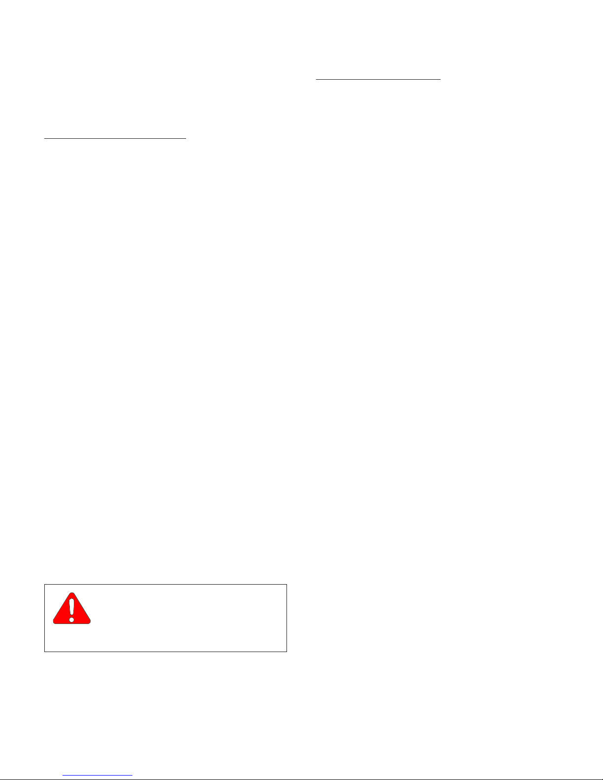
(1) Refer to Figure 1-2 to determine the location of
the model number and serial number of the unit
and record this data.
SMI
7100
CA7681
Figure 1-2. Model Number / Serial
Number Location
© Schaerer Mayfield USA, Inc. 2004
Page 1-8Printed in U.S.A.
Page 15

1.6 Special Tools
Table 1-2 lists all of the special tools needed to repair
the unit, how to obtain the special tools, and the purpose of each special tool.
Table 1-2 is on the following page.
Table 1-2. Special Tools List
SECTION I
GENERAL INFORMATION
Description of Special Tool
Multimeter Commercially Available Any Type Used to perform continuity and voltage checks.
Pin Extractor (has
interchangable bits - M3x0.5,
M4x0.7, M5x0.8, M6x1.0,
1/4-20, 10-24, and 5/16-18)
Spanner Wrench - locking nut Schaerer Mayfield USA
Spanner Wrench - brass pivot
puck
Retaining Bolt Schaerer Mayfield USA
Spanner Wrench - retainer cap Schaerer Mayfield USA
Pressure Relief Valve Test
Harness
Blanking Plug Kit Schaerer Mayfield USA
Soldering Iron Commercially Available Any Type Used to connect wires to terminals with solder.
60 / 40 Solder Commercially Available Any Type Type of solder which should be used when
Internal retaining ring pliers Commercially Available Any Type Used to remove snap rings which secure bearings
Torque Wrench Commercially Available Any Type Used to tighten hardware to specified torque
Transport Tool Schaerer Mayfield USA
Tipping Tool Schaerer Mayfield USA
Manufacturer's
Name / Address / Phone
Schaerer Mayfield USA
4900 Charlemar
Drive Cincinnati, Ohio 45227
(800) 755-6381
4900 Charlemar
Drive Cincinnati, Ohio 45227
(800) 755-6381
Schaerer Mayfield USA
4900 Charlemar
Drive Cincinnati, Ohio 45227
(800) 755-6381
4900 Charlemar
Drive Cincinnati, Ohio 45227
(800) 755-6381
4900 Charlemar
Drive Cincinnati, Ohio 45227
(800) 755-6381
Schaerer Mayfield USA
4900 Charlemar
Drive Cincinnati, Ohio 45227
(800) 755-6381
4900 Charlemar
Drive Cincinnati, Ohio 45227
(800) 755-6381
4900 Charlemar
Drive Cincinnati, Ohio 45227
(800) 755-6381
4900 Charlemar
Drive Cincinnati, Ohio 45227
(800) 755-6381
Manufacturer's
Part Number
M05390 Used to pull pins which secure cylinders, handles,
etc. in place. Can also be used to remove caster
fork.
M07235 Used to remove locking nut which secures top of
column cylinder in column.
M07236 Used to remove brass pivot puck which secures
top of column cylinder in column.
M07407 Used to hold rod of column cylinder stationary,
while special tools, M07235 and M07236 are
used.
M07161 Used to remove retainer cap which secures
latching mechansim in place.
M07443 Used to adjust crack settings of motor pump
pressure relief valves and outrigger pressure relief
valve.
502-0176-00 Used to cap the end of hydraulic lines to allow
pressure checks to be made.
soldering wires on surgery table.
in base of cylinders.
values.
502-0169-00 A dolly type tool which is used to transport Model
7100 or 7300 surgical tables around.
502-0168-00 Used to tip over Model 7100 or 7300 surgical
tables to access base of table for servicing.
Purpose of Special Tool
© Schaerer Mayfield USA, Inc. 2004
Page 1-9Printed in U.S.A.
Page 16

SECTION I
GENERAL INFORMATION
© Schaerer Mayfield USA, Inc. 2004
Page 1-10Printed in U.S.A.
Page 17
TESTING AND TROUBLESHOOTING
SECTION II
TESTING AND TROUBLESHOO TING
SECTION II
2.1 Operational Test
In order to effectively diagnose malfunctions of the 7300
Modular Surgical Table, it may be necessary to perform
an operational test as follows:
DANGER
Refer to the Operator Manual for
complete instructions on operating the
surgical table. Failure to do so could result in
personal injury.
Power must be supplied to the unit to measure
the voltage at the Test Points. Do not touch any
bare wires or terminals while making these
voltage checks. Failure to do so may result in
electrical shock which could result in serious
personal injury or death.
NOTE
The Operational Test, for the most part, only describes what should happen when the surgical table is
operated. If the surgical table does something other
than described, a problem has been discovered.
Refer to the Troubleshooting Guide to determine the
cause of the problem and its correction.
(1 ) Plug power cord into table's plug receptacle.
See Figure 2-1, Sheets 1 and 2.
(8 ) Move the surgery table around.
(9) Observe. The casters should swivel freely and
the table should roll easily on the casters. The
table should not wobble.
(10) Press ENABLE button on hand control.
(11) Observe. The motor pump should run and the
main floor lock cylinders should extend. After
eight seconds, the motor pump should stop
running. Then the motor pump should begin
running again and the outrigger floor lock
cylinders should extend. After six seconds, the
motor pump should stop running. The hand
control display should read LOCKING FLOOR
while the floor lock cylinders are extending.
(12) Insert pins of Head Section into sockets on
column end of table. Rotate latch handles to
locked position (to move latch handles to locked
position, rotate them away from you) and then
pull and push on head sections.
(13) Observe. When the latch handles are rotated to
the locked position, the section being installed
should now be held securely in place. No side-
to-side or in-and-out movement should be
possible.
(2) Observe. The line power pilot lamp should
illuminate.
(3 ) Unplug the power cord.
(4 ) Press ENABLE button on hand control.
(5) Observe. The hand control display should
illuminate and display the current table position
and battery charge level (XX POSITION and
BATT LEVEL XX. After 10 seconds, the hand
control display should extinguish.
(6 ) Press and hold UNLOCK & ENABLE buttons on
hand control for three seconds.
(7) Observe. The motor pump should run and the
table should lower (floor lock cylinders should
retract) until table is on its casters. The hand
control display should read UNLOCKING
FLOOR and then ON WHEELS.
© Schaerer Mayfield USA, Inc. 2004
(14) Press the ENABLE and REVERSE POSITION
buttons on hand control.
(15) Observe. The hand control display should read
REVERSE POSITION.
(16) Press the FLEX button and then REFLEX
button.
(17) Observe. Hand control display should indicate
these positions are "disabled" and cannot be
used when table is in REVERSE POSITION.
(18) Press the ENABLE and NORMAL POSITION
buttons on hand control.
(19) Observe. The hand control display should read
NORMAL POSITION.
Page 2-1 Printed in U.S.A.
Page 18
SECTION II
TESTING AND TROUBLESHOOTING
C
LINE POWER
PILOT LAMP
HEAD
SECTION
HAND
CONTROL
LATCH
HANDLE
EMERGENCY
OVERRIDE
PANEL
FOOT
CONTROL
RELEASE
HANDLE
ENABLE
LOCK
LEVEL
SMI
7300
SMI
PLUG
B
DISABLE
UNLOCK
7100
SMI
7300
BACK
SECTION
RECEPTACLE
A
SEAT SECTION
(PELVIC BASE)
POWER
CORD
TRENDEL-
ENBURG
REVERSE
TRENDEL-
ENBURG
TABLE
UP
TABLE
DOWN
FLOOR
LOCK
CYLINDERS
LATERAL
TILT
LEFT
LATERAL
TILT
RIGHT
Figure 2-1. Operational Test (Sheet 1 of 2)
LOCKED
POSITION
AUTO
CAPTURE
POSITION
UNLOCKED
POSITION
LATCH HANDLE
POSITIONS
(TYP. 2 PLACES)
CA819700
© Schaerer Mayfield USA, Inc. 2004
Page 2-2Printed in U.S.A.
Page 19
SECTION II
TESTING AND TROUBLESHOOTING
BUTTONS
SMI
DISABLE
LATERAL
TILT LEFT
SYSTEM
OVERRIDE
SYSTEM
OVERRIDE
7300
DISABLE
TABLE
DOWN
TABLE
UP
TRENDELENBURG
REVERSE
TRENDELENBURG
UNLOCKLOCK
SEAT
UP
SEAT
DOWN
HAND
CONTROL
DISPLAY
ENABLE
NORMAL
POSITION
TRENDELENBURG
TABLE
UP
LATERAL
TILT LEFT
SEAT
UP
FLEX
ENABLE
LOCK
DISABLE
NORMAL
REVERSE
POSITION
TREND
POSITION
REV TREND
HEIGHT UP
HEIGHT DOWN
TILT L
TILT R
SEAT UP SEAT DOWN
FLEX
UNLOCKLEVEL
SMI
LEVEL
(RETURN TO)
DISABLE
REVERSE
POSITION
REVERSE
TRENDELENBURG
TABLE
DOWN
LATERAL
REFLEX
TILT RIGHT
SEAT
DOWN
7300
REFLEX
UNLOCK
LATERAL
TILT RIGHT
LEVEL
UNLOCK
(RETURN TO)
Figure 2-1. Operational Test (Sheet 2 of 2)
(20) Press the ENABLE button and then press the
TABLE UP, TABLE DOWN,
TRENDELENBURG, REVERSE
TRENDELENBURG, LATERAL TILT LEFT,
LATERAL TILT RIGHT, SEAT UP, SEAT
DOWN, FLEX, and REFLEX buttons, running
each function thru its full range of motion, and
checking its speed and range of motion performance.
(21) Observe. The table performance should meet
the following specifications:
Range Of Motion:
Table Top Height (Adjustable) ........... 27.7 (± 0.2) in. to
43.9 (± 0.2) in.
(70 to 112 cm)
Trendelenburg ....................................... 0° to 28° (±1°)
Reverse Trendelenburg ......................... 0° to -28° (±1°)
Lateral Tilt................. 0° to -18° (±1°) in either direction
CA819800
Seat Section ........... + 25° (±1°) to -40° (±1°) in relation
to back section
Coordinating Flex (Normal Position):
Trendelenburg .................. +20° (±5°) above horizontal
Coordinating Reflex (Normal Position):
Trendelenburg ................... -12° (±5°) below horizontal
Table Speed (Table in normal orientation, full battery
charge, ambient oil temp.):
Extend Column Fully................... 16.0 to 21.0 seconds
Retract Column Fully .................. 16.0 to 21.0 seconds
Reverse Trend. to Trend. ............ 20.5 to 24.5 seconds
Trend. to Reverse Trend. ............ 16.0 to 20.0 seconds
Lat. Tilt R to Lat. Tilt L .................. 9.5 to 12.5 seconds
Lat. Tilt L to Lat. Tilt R ................ 10.0 to 13.0 seconds
Seat Down to Seat Up ................ 18.0 to 21.0 seconds
Seat Up to Seat Down ................ 18.5 to 21.5 seconds
© Schaerer Mayfield USA, Inc. 2004
Page 2-3Printed in U.S.A.
Page 20
SECTION II
TESTING AND TROUBLESHOOTING
(22) Press the ENABLE button and then press the
LEVEL button until the table reaches its level
position. Using a protractor, check the table top
to ensure it is level within ±2°.
(23) Observe. The table top should move to a level
position within ±2° as follows: The lateral tilt
function should level out first; then a sequence
of the Seat, and Trendelenburg functions should
move, with each function moving no more than
10° at a time.
(24) Squeeze the release handle on the head section
and move the head section thru its full range of
motion.
(25) The head section should move smoothly and
should not take excessive force. The head
section should meet the following range of
motion specifications:
Head Section:
Mounted on Head End ........... +30° (±3°) to -30° (±3°)
Mounted on Foot End ............ +30° (±3°) to -75° (±5°)
(26) Move head section to level position and then
place approximately 40 lbs. (18 kgs) at Point C
(head section). Observe head section for two to
three minutes.
(27) Observe. The head section should not drift.
(28) Place approximately 400 lbs. (181.4 kg) of
weight on table top as follows: 28 lbs. (12.7 kg)
at Point C (head section), 152 lbs. (69 kg) at
Point B (back section), and 168 lbs. (76.2 kg) at
Point A (seat section).
(33) Observe. Each function should move as
depicted by the illustration on its button.
(34) Press each function button on the foot control.
Then place the table top in REVERSE position.
Then press each function button on the foot
control again.
(35) Each function should move as depicted when
table top is in NORMAL position. The table
should not operate, using the foot control, when
the table top is in REVERSE position.
(36) Plug power cord into table's power receptacle.
DANGER
Electrical power must be connected to
perform the following steps. Do not
touch any bare wires or terminals. Failure to do
so could cause an electrical shock which could
result in serious personal injury or death.
(37) See Figure 2-2 for this step. Check for 32.5
VAC ± 2 VAC across Test Points C and D and
across Test Points D and E.
(38) Observe. There should be 32.5 VAC ±2 VAC
across
(39) See Figure 2-2 for this step. Check for 27.7
VAC ± 2 VAC across Test Points F and G and
across Test Points H and J. Check for 27.8
VAC ±2 VAC across Test Points K and L.
(40) Observe. The proper voltages should be
present across
both
sets of test points.
each
set of test points.
(29) Press ENABLE button and then press TABLE
UP and TABLE DOWN buttons to run column
function up and down several times.
(30) Observe. Column function should move up and
down steadily and smoothly. No binding
condition should be evident, especially when
column is lowering. There should be no exces-
sive side-to-side play in column assembly.
(31) Remove weight from table top.
(32) Press and hold the SYSTEM OVERRIDE button
while pressing the function buttons, one at a
time, on the emergency override panel.
© Schaerer Mayfield USA, Inc. 2004
Page 2-4Printed in U.S.A.
Page 21
SECTION II
TESTING AND TROUBLESHOOTING
POWER CORD
RECEPTACLE
5 amp.
FUSE
L
115
N
VAC
5 amp.
FUSE
Note
Wire colors may change
without notification
ST5b
3
1
11
9
15
5
7
8
6
10
2
12
141316
4
RED
RED
RED
RED
RED
BLACK
BLACK
BROWN
BLUE
BLACK
BLACK
BLACK
BLACK
WHITE
VIOLET
GREEN
YELLOW
ORANGE
RED
4
5
FOOT
CONTROL
6
PORT
1
NOTE: FOOT AND HAND CONTROL
PLUGS ARE POSITIONED TO VIEW
TERMINAL (BACK) END.
5
6
HAND
CONTROL
7
PORT
1
2
GREEN
3
2
4
3
= DENOTES "TEST POINTS"
!!
LINE POWER
PILOT LAMP
A
BROWN
BROWN
RFI
FILTER
BLUE
YELLOW / GREEN
YELLOW / GREEN
ST6
12
GREY / PINK
GREY / WHITE
BROWN / GREY
WHITE / GREEN
BROWN / GREEN
YELLOW / WHITE
BROWN / YELLOW
BLUE
GREEN
YELLOW
RED
BROWN
GREY
GREY
BLUE
GREEN
WHITE
YELLOW
RED
BROWN
9111413161518172019
10
RED / BLUE
B
7
8
WHITE
BLUE
YELLOW / GREEN
3
5
6
4
GREY
VIOLET
WHITE
YELLOW
1
2
BLUE
M
N.C.
80° c
(176° F)
FUSE
OUTRIGGER
FLOOR LOCK
STATUS SWITCH
BLACK
2
WHITE
GREY
WHITE
N
100° c
MOTOR
(212° F)
PUMP
SECONDARY
L2
#2
THERMAL
RED
1
BROWN
N.O.
N.O.
N.C.C.
(SWITCHES
SHOWN IN
UNTRIPPED
POSITION)
BROWN
FUSE
MAIN FLOOR
LOCK STATUS
SWITCH
BLACK
2
WHITE
Q
RED
1
BROWN
N.C.
P2
80° c
(176° F)
L1
PRIMARY
THERMAL
FUSE
N.O.
N.C.C.
4
BROWN
X
ST3
W
8
6
10
12
7
9 11
PINK
WHITE
GREEN
YELLOW
RED / BLUE
GREY / PINK
RED
R
2
1 3 5
BLUE
GREY
VIOLET
BLACK
P
ST10
8
10 12 14
6
4
2
7
1 3 5
13
9
11
RED
PINK
BLUE
BLACK
BROWN
VIOLET
GREEN
YELLOW
RED / BLUE
GREY / PINK
WHITE / GREEN
BROWN / GREEN
RED
PINK
BLUE
GREY
RED / BLUE
BLACK
GREEN
VIOLET
BROWN
YELLOW
GREY / PINK
3
911
5
7
1
2
12
10
6
8
4
St23
WHITE
K
ST3a
ST2a
TRANSFORMER
THERMAL
FUSE
BLACK
RED
THERMAL
FUSE
YELLOW
BLACK
RED
2
2
ST1
ST1
3
3
4
4
ST8
(P2)
1
1
CHARGING / POWER
ST8
BLACK
RED
BLACK
C5
ST3a
(BATT. -)
C
D
E
9
10
V
DRIVER BOARD
T
9
10
RED
YELLOW
BLUE
BLACK
BROWN
2
1 3 5
7
8
7
8
WHITE
VIOLET
4
S
ST5a
ST5a
ST2a
(BATT. +)
5
6
5
6
GREY
GREY
6
3
4
3
4
VIOLET
WHITE
8
7
ST2b
2
3
1
9111413161518172019
5
7
1 3 5
8
6
10
2
4
MAIN CONTROLLER BOARD
1
2
3
WHITE
GREEN
BROWN
2
4
2
1
3
4
St35
BLACK
GREEN
BROWN
YELLOW
GREEN
BROWN
YELLOW
H
10 amp.
FUSE
1
1
St1
2 2
RED
PINK
BROWN
YELLOW
RED
RED
2
1
3
4
BLUE
St37
5
6
7
8
GREY
RED
2
1
3
4
BLUE
St36
5
6
WHITE
7
8
GREY
J
SEAT POSITION
YELLOW
SENSOR
16
14 13
12
10
8
6
4
2
RED
12
ST6
St1
St4
15
11
9
7
St5b
5
3
1
LATERAL TILT
POSITION SENSOR
GREEN
2
1
1
3
3
4
5
6
St33
St32
U
ST7a
4
(PUMPS +)
1
2
1
2
BLUE
RED
10
9
6
ST2b
ST9 a & b
ST7
(P1)
BLACK
YELLOW
8
7
WHITE
FUSE
40 amp.
ST4
2
1
BLACK
BROWN
10
9
GREEN
BROWN
L
- +- +- +-
+
BATTERY BATTERY BATTERY BATTERY
ST9a
RED
ST9b
RED
F
2
1
G
RED
GREY
WHITE
BLACK
BROWN
8
6
4
2
7
1 3 5
ST7
8
6
4
2
7
1 3 5
ST7
TRENDELENBURG
POSITION SENSOR
2
3
100° c
MOTOR
(212° F)
PUMP
SECONDARY
L2
#1
THERMAL
N.O.
ST4
FUSE
PI
L1
PRIMARY
THERMAL
WHITE
BLACK
BLACK
GREEN
10
9
10
9
YELLOW
8
10
6
4
2
12
7
9 11
1 3 5
ST3
ON ON
12
8
10 12 14
6
4
2
7
1 3 5
13
9
11
ST10
1
Figure 2-2. Voltage Checks
© Schaerer Mayfield USA, Inc. 2004
CA819900
Page 2-5Printed in U.S.A.
Page 22

SECTION II
TESTING AND TROUBLESHOOTING
2.2 Troubleshooting Procedures
Table 2-1 is a Troubleshooting Guide which is used to
determine the cause of the malfunction.
Table 2-1. Troubleshooting Guide
Problem Symptom Probable Cause Check Correction
Table seems powerless
even when plugged into a
wall outlet.
Line Power Pilot Lamp
does not illuminate (with
power cord plugged in).
Line Power Pilot Lamp
illuminates, but batteries
do not recharge and table
is powerless (with power
cord plugged in).
Line Power Pilot Lamp
illuminates, but table is
powerless.
Facility circuit breaker
providing power to table is
tripped.
One of two 5 amp fuses in
the power cord receptacle is
blown.
RFI filter is blown. See Figure 5-1 for this
Line power pilot lamp is
burned out.
Wires or wire connections
between power cord
receptacle and transformer
are broken, loose or dirty.
Thermal fuse(s) in
transformer are blown.
Transformer is blown. See Figure 5-1 for this
Charging / power driver
board is malfunctioning.
Wires or wire connections
between transformer and
charging / power driver
board are broken, loose, or
dirty.
10 amp fuse on main
controller board is blown.
Check to see if facility
circuit breaker is tripped.
Remove both 5 amp
fuses from power cord
receptacle and perform a
continuity check on the
fuses.
check. Check for 115
VAC ± 5.0 VAC across
Test Points A and B.
Replace suspect line
power pilot lamp with
known working line
power pilot lamp.
Perform a continuity
check on all suspect
wires or connections.
See Figure 5-1 for this
check. Check for 32.5 ±
2.0 VAC across Test
Points C and D and
across Test Points D
and E.
check. Check for 32.5 ±
2.0 VAC across Test
Points C and D and
across Test Points D
and E.
See Figure 5-1 for this
check. Check for 27.7
+/- 0.3 VDC across Test
Points F and G. Check
for 27.7 +/- 0.3 VDC
across Test Points H and
J. Check for 27.8 +/- 0.3
VDC across Test Points
K and L.
Perform a continuity
check on all suspect
wires or connections.
Perform continuity check
on 10 amp fuse.
If circuit breaker is tripped,
determine what caused the
circuit breaker to trip, correct
the problem, and then reset /
replace circuit breaker.
Replace any blown 5 amp
fuses.
If 115 VAC ± 5.0 VAC is not
present across Test Points A
and B, replace RFI filter.
Refer to para 4.35.
Replace line power pilot lamp.
Refer to para 4.37.
Clean any dirty connections.
Tighten any loose
connections. Replace any
broken connectors or wires.
If 32.5 VAC ± 2.0 VAC is not
present across one or both of
the Test Point groups, replace
the transformer. Refer to
para 4.36.
If 32.5 VAC ± 2.0 VAC is not
present across one or both of
the Test Point groups, replace
the transformer. Refer to
para 4.36.
If proper voltage is not
present at Test Points,
replace charging / power
driver board. Refer to para
4.38.
Clean any dirty connections.
Tighten any loose
connections. Replace any
broken connectors or wires.
Replace 10 amp fuse. See
Figure 5-1 for fuse location.
© Schaerer Mayfield USA, Inc. 2004
Page 2-6Printed in U.S.A.
Page 23

Problem Symptom Probable Cause Check Correction
Table operates when
power cord is plugged in,
but will not operate when
power cord is unplugged.
Table 2-1. Troubleshooting Guide
When ENABLE button on
hand control is pressed, its
display does not illuminate
(with power cord
unplugged).
TESTING AND TROUBLESHOOTING
40 amp fuse on charging /
power driver board is blown.
10 amp fuse on main
controller board is blown.
Batteries are dead and are
not supplying charging /
power driver board with
enough power to operate.
See Figure 5-1 for this
check. Check fuse
visually or perform
continuity check on fuse
(may need to check
secondary thermal fuse
of motor pump. If blown,
thermal fuse will cause
40 amp fuse to blow).
Perform continuity check
on 10 amp fuse.
See Figure 5-1 for this
check. Check individual
batteries by checking for
13.2 +/- 0.4 VDC across
terminals of each battery
(Test Points M and N).
SECTION II
Replace 40 amp fuse. See
Figure 5-1 for fuse location.
Replace 10 amp fuse. See
Figure 5-1 for fuse location.
If 13.2 +/- 0.4 VDC is not
present across Test Points,
replace batteries. Refer to
para 4.39.
Batteries do not recharge
in 6 to 8 hours from low
charge.
Hand control does not
work.
Batteries do not recharge
very quickly.
When ENABLE button on
hand control is pressed, its
display does not illuminate.
Charging / power driver
board is malfunctioning.
One of thermal fuses in
transformer is blown.
Batteries are dead. See Figure 5-1 for this
10 amp fuse on main
controller board is blown.
Main controller board or
hand control board is
malfunctioning.
Wires or wire connections
between main controller
board, distribution board,
and hand control port are
broken, loose or dirty.
Motor pump secondary
thermostat is closed creating
a direct short to ground,
causing 40 amp fuse on
charging / power driver
board to blow.
See Figure 5-1 for this
check. Check for 27.7
+/- 0.3 VDC across Test
Points F and G.
See Figure 5-1 for this
check. Check for 32.5
+/- 2.0 VAC across Test
Points C and D, and
across Test Points D
and E.
check. Check individual
batteries by checking for
13.2 +/- 0.4 VDC across
terminals of each battery
(Test Points M and N).
Perform continuity check
on 10 amp fuse.
See Figure 5-1 for this
check. Check for 5.0
VDC across Test Points
P and Q. If 5 VDC is
present, check for 5.0
VDC across Test Points
Q and R within 10
seconds of pressing
ENABLE button on hand
control.
See Figure 5-1 for this
check. Perform a
continuity check on all
suspect wires or
connections.
See Figure 5-1 for this
check. Check for a
resistance value of 0
ohms between Test
Points S and T for motor
# 1 or Test Points U and
V for motor # 2.
If proper voltage is not
present at Test Points,
replace charging / power
driver board. Refer to
para 4.32.
If 32.5 +/- 2.0 VAC is not
present across one or both of
the Test Point groups, replace
the transformer. Refer to
para 4.36.
If 13.2 +/- 0.4 VDC is not
present across Test Points,
replace batteries. Refer to
para 4.39.
Replace 10 amp fuse. See
Figure 5-1 for fuse location.
If 5.0 VDC is not present
across Test Points P and Q,
the main controller board is
malfunctioning. If 5.0 VDC is
not present across Test Points
Q and R during check, then
main controller board or hand
control board is
malfunctioning. Refer to para
4.31 or 4.5.
Clean any dirty connections.
Tighten any loose
connections. Replace any
broken connectors or wires.
Replace malfunctioning motor,
secondary thermostat, and 40
amp fuse. Refer to para 4.26
and 4.41.
© Schaerer Mayfield USA, Inc. 2004
Page 2-7Printed in U.S.A.
Page 24

SECTION II
TESTING AND TROUBLESHOOTING
Table 2-1. Troubleshooting Guide
Problem Symptom Probable Cause Check Correction
Hand control does not
work - Continued.
When ENABLE button on
hand control is pressed, its
display does not illuminate
- Continued.
Display of hand control
board is malfunctioning.
Replace suspect hand
control board with known
working hand control
board.
Replace hand control board.
Refer to para 4.5.
Foot control does not
work.
When a button on hand
control is pressed, error
code E15 displays.
When a function button on
hand control is pressed,
the motor pump does not
run and no error codes
display.
Foot control operates fine
sometimes, but not every
time.
When foot switch on foot
control is pressed, nothing
happens (hand control
display should illuminate
when foot switch is
depressed).
Button board is
malfunctioning.
Button board is
malfunctioning. One of two
button switches for a
function is stuck in closed
position or will not close.
Hand control board is
malfunctioning.
Button board is
malfunctioning.
Main controller board is
malfunctioning.
Wires or wire connections
between main controller
board, distribution board,
and hand control port are
broken, loose or dirty.
Table is in reverse
orientation.
The hand control or
emergency override panel is
being used (hand control
and / or emergency override
panel takes priority over foot
control).
One of two foot switches for
a function is stuck in closed
position or will not close.
Replace suspect button
board with known
working button board.
Perform a continuity
check on both button
switches of suspect
function (when a button
switch is pressed, there
should be continuity
between its two
terminals).
Replace suspect hand
control board with known
working hand control
board.
Replace suspect button
board with known
working button board.
Replace suspect main
controller board with
known working main
controller board.
See Figure 5-1 for this
check. Perform a
continuity check on all
suspect wires or
connections.
Foot control is locked out
from being used when
table top is in reverse
orientation - foot control
may only be used when
table top is in normal
orientation.
Check if problem occurrs
only when hand control
or emergency override
panel is being used.
See Figure 5-1 for this
check. Perform a
continuity check on both
foot switches of suspect
function (when foot
switch is pressed, there
should be continuity
between its two
terminals).
Replace button board. Refer
to para 4.4.
If check fails, replace button
board. Refer to para 4.4.
Replace hand control board.
Refer to para 4.5.
Replace button board. Refer
to para 4.4.
Replace main controller
board. Refer to para 4.31.
Clean any dirty connections.
Tighten any loose
connections. Replace any
broken connectors or wires.
Use hand control or set up
table top in normal orientation.
Inform operator that Foot
Control cannot be used when
table is in reverse orientation.
Do not use foot control
simultaneously with hand
control or emergency override
panel. Inform operator of
Emergency Override Panel,
Hand Control, and Foot
Control priorities.
If check fails, replace foot
switch pad.
© Schaerer Mayfield USA, Inc. 2004
Page 2-8Printed in U.S.A.
Page 25

Problem Symptom Probable Cause Check Correction
Foot control does not work
-Continued
Error code E01 (Floor
Lock Status Switch Is Not
Responding) displays on
hand control.
Table 2-1. Troubleshooting Guide
When foot switch on foot
control is pressed, nothing
happens (hand control
display should illuminate
when foot switch is
depressed) -Continued.
Floor lock cylinders do not
extend or retract properly
and error code E01
appears on hand control.
Floor lock cylinders extend
properly, but error code
E01 appears on hand
control.
TESTING AND TROUBLESHOOTING
Foot control interface board
is malfunctioning.
10 amp fuse on main
controller board is blown.
Main controller board or foot
control interface board is
malfunctioning.
Wires or wire connections
between main controller
board, distribution board,
and hand control port are
broken, loose or dirty.
Check valve(s) for main floor
lock cylinder(s) or outrigger
floor lock cylinder(s) are
stuck open, allowing floor
lock cylinders to retract after
extending.
Foreign matter in main floor
lock or outrigger floor lock
valve spool.
Outrigger pressure relief
valve is malfunctioning,
preventing outrigger
cylinders from extending
fully.
Inside surfaces of main floor
lock cylinder(s) or outrigger
floor lock cylinder(s) are dirty
/ covered with foreign
matter, which prevents the
cylinder(s) from extending or
retracting fully.
Main floor lock status switch
remains tripped after main
floor locks have extended
(out of adjustment).
Main floor lock status switch
is malfunctioning - stuck
open.
Replace suspect foot
control interface board
with known working foot
control interface board.
Perform continuity check
on 10 amp fuse.
See Figure 5-1 for this
check. Check for 5.0
VDC across Test Points
P and W. If 5.0 VDC is
present, check for 5.0
VDC across Test Points
W and X within 10
seconds of pressing a
foot button on foot
control.
See Figure 5-1 for this
check. Perform a
continuity check on all
suspect wires or
connections.
Remove check valve(s)
and check for foreign
matter.
Remove valve spool(s)
and check for foreign
matter. Flush out valve
spool manifold with oil.
Replace suspect
pressure relief valve with
known working pressure
relief valve.
Check for foreign matter
on inside surfaces of
floor lock cylinders.
Check if status switch is
tripped.
See Figure 5-1 for this
check. Perform
continuity check on
normally closed status
switch (switch untripped
= continuity).
SECTION II
Replace foot control interface
board. Refer to para 4.44.
Replace 10 amp fuse. See
Figure 5-1 for fuse location.
If 5.0 VDC is not present
across Test Points P and W,
the main controller board is
malfunctioning. If 5.0 VDC is
not present across Test Points
W and X during check, then
main controller board or foot
control interface board is
malfunctioning. Refer to para
4.31 or 4.44.
Clean any dirty connections.
Tighten any loose
connections. Replace any
broken connectors or wires.
Remove and clean check
valve(s). Replace any
damaged pilot pistons or
check valves.
Push on manual release pin of
valve spool. If still stuck,
remove valve spool(s) and
check for foreign matter.
Flush out valve spool manifold
with oil.
Replace outrigger pressure
relief valve and spring. Refer
to para 4.30.
Disassemble and clean floor
lock cylinder(s).
If necessary, adjust main floor
lock status switch. Refer to
para 4.42.
If malfunctioning, replace main
floor lock status switch. Refer
to para 4.42.
© Schaerer Mayfield USA, Inc. 2004
Page 2-9Printed in U.S.A.
Page 26

SECTION II
TESTING AND TROUBLESHOOTING
Table 2-1. Troubleshooting Guide
Problem Symptom Probable Cause Check Correction
Error code E01 (Floor
Lock Status Switch Is
Not Responding)
displays on hand
control - Continued.
Error Code E02
(Overcurrent - Motor
#1) displays on hand
control.
Error code E03
(Overcurrent - Motor
#2) displays on hand
control.
Error code E04
(Motor Driver Failure)
displays on hand
control.
Floor lock cylinders do
not extend or retract
properly and error code
E01 appears on hand
control - Continued.
Floor lock cylinders do
not retract properly and
Error code E01 appears
on hand control.
When function is
selected, error code E02
appears on hand
control.
When function is
selected, error code E03
appears on hand
control.
When function is
selected, error code E04
appears on hand
control.
Outrigger floor lock status switch
remains tripped after outrigger
floor locks have extended (out of
adjustment).
Outrigger floor lock status switch is
malfunctioning - stuck open.
Wires or wire connections
between floor lock status switches
and main controller board are
broken, loose or dirty.
One of the floor lock status
switches is malfunctioning.
Retaining ring which holds ouside
floor lock sleeve onto floor lock
cylinder piston is missing.
Motor #1 is malfunctioning. Replace suspect motor #1
Charging / power driver board is
malfunctioning.
Motor #2 is malfunctioning. Replace suspect motor #2
Charging / power driver board is
malfunctioning.
Wires or wire connections
between charging / power driver
board and pumps are broken,
loose, or dirty.
Charging / power driver board is
malfunctioning.
Motor is burned out (most likely
motor #1).
Check if status switch is
tripped.
See Figure 5-1 for this
check. Perform continuity
check on normally closed
status switch (switch
untripped = continuity).
See Figure 5-1 for this
check. Perform a
continuity check on all
suspect wires or
connections.
Perform continuity check
on N.C. floor lock status
switch (switch untripped =
continuity).
Check to see if retaining
ring is missing.
with known working motor
pump.
Replace suspect charging
/ power driver board with
known working board.
with known working motor
pump.
Replace suspect charging
/ power driver board with
known working board.
See Figure 5-1 for this
check. Perform a
continuity check on all
suspect wires or
connections.
Replace suspect charging
/ power driver board with
known working board.
Replace suspect motor
with known working
motor. (If only COLUMN
UP function causes error
code E04, motor #2 could
be malfunctioning - motor
#2 only runs for this
function during normal
operation).
If necessary, adjust outrigger
floor lock status switch.
Refer to para 4.42.
If malfunctioning, replace
outrigger floor lock status
switch. Refer to para 4.42.
Clean any dirty connections.
Tighten any loose
connections. Replace any
broken connectors or wires.
If necessary, adjust or
replace floor lock status
switch. Refer to para 4.42.
Replace retaining ring.
Replace motor #1. Refer to
para 4.26.
Replace charging / power
driver board. Refer to para
4.32.
Replace motor #2. Refer to
para 4.26.
Replace charging / power
driver board. Refer to para
4.32.
Clean any dirty connections.
Tighten any loose
connections. Replace any
broken connectors or wires.
Replace charging / power
driver board. Refer to para
4.32.
Replace motor. Refer to
para 4.26.
© Schaerer Mayfield USA, Inc. 2004
Page 2-10Printed in U.S.A.
Page 27

Problem Symptom Probable Cause Check Correction
Error code E05 (Valve
Driver Failure) displays on
hand control.
Error code E06
(Footswitch Failure)
displays on hand control.
Error code E07
(Trendelenburg Position
Sensor Failure) displays
on hand control.
Table 2-1. Troubleshooting Guide
When ENABLE button is
pressed, or a function
button is selected, error
code E05 appears on
hand control.
When a footswitch button
is depressed, error code
E06 appears on hand
control.
When ENABLE button is
pressed, or a function
button is selected, error
code E07 appears on
hand control.
TESTING AND TROUBLESHOOTING
A valve spool solenoid is
malfunctioning.
Wires or wire connections
between valve spool
solenoid and main controller
board are broken, loose or
dirty.
Main controller board is
malfunctioning - valve driver
circuitry is malfunctioning.
One of two foot switches for
a function is stuck in closed
position or will not complete
circuit when depressed.
Foot control interface board
is malfunctioning.
Wires or wire connections
between foot switches and
foot control interface board
are broken, loose or dirty.
Trendelenburg position
sensor is malfunctioning.
Wires or wire connections
between Trendelenburg
position sensor, distribution
board, and main controller
board are broken, loose, or
dirty.
Main controller board is
malfunctioning.
Press and hold the
SYSTEM OVERRIDE
button on the emergency
panel, while pressing,
one at a time, all the
remaining function
buttons on the
emergency panel (except
for DISABLE button). All
functions should operate
except for function with
malfunctioning valve
spool solenoid.
See Figure 5-1 for this
check. Perform a
continuity check on all
suspect wires or
connections.
Replace suspect main
controller board with
known working main
controller board.
See Figure 5-1 for this
check. Perform a
continuity check on both
foot switches of suspect
function (switch not
depressed = open /
switch depressed =
continuity.
Replace suspect foot
control interface board
with known working foot
control interface board.
See Figure 5-1 for this
check. Perform a
continuity check on all
suspect wires or
connections.
Replace suspect
Trendelenburg position
sensor with known
working position sensor.
See Figure 5-1 for this
check. Perform a
continuity check on all
suspect wires or
connections.
Replace suspect main
controller board with
known working main
controller board.
SECTION II
Replace malfunctioning valve
spool solenoid. Refer to para
4.22 or 4.23.
Clean any dirty connections.
Tighten any loose
connections. Replace any
broken connectors or wires.
Replace main controller
board. Refer to para 4.31.
If check fails, replace foot
switch pad.
Replace foot control interface
board. Refer to para 4.44.
Clean any dirty connections.
Tighten any loose
connections. Replace any
broken connectors or wires.
Replace Trendelenburg
position sensor. Refer to para
4.11.
Clean any dirty connections.
Tighten any loose
connections. Replace any
broken connectors or wires.
Replace main controller
board. Refer to para 4.31.
© Schaerer Mayfield USA, Inc. 2004
Page 2-11Printed in U.S.A.
Page 28

SECTION II
TESTING AND TROUBLESHOOTING
Table 2-1. Troubleshooting Guide
Problem Symptom Probable Cause Check Correction
Error code E08 (Tilt
Position Sensor Failure)
displays on hand control.
Error code E09 (Seat
Position Sensor Failure)
displays on hand control.
Error code E11 (Internal
RAM / Register Failure)
displays on hand control.
Error code E12
(Calibrating data Failure)
displays on hand control.
When ENABLE button is
pressed, or a function
button is selected, error
code E08 appears on
hand control.
When ENABLE button is
pressed, or a function
button is selected, error
code E09 appears on
hand control.
When ENABLE button is
pressed, error code E11
appears on hand control.
When ENABLE button is
pressed, error code E12
appears on hand control.
Tilt position sensor is
malfunctioning.
Wires or wire connections
between tilt position sensor,
distribution board, and main
controller board are broken,
loose or dirty.
Main controller board is
malfunctioning.
Seat position sensor is
malfunctioning.
Wires or wire connections
between seat position
sensor, distribution board,
and main controller board
are broken, loose or dirty.
Main controller board is
malfunctioning.
Battery power level is too
low to properly power table.
Main controller board is
malfunctioning.
Replace suspect tilt
position sensor with
known working position
sensor.
See Figure 5-1 for this
check. Perform a
continuity check on all
suspect wires or
connections.
Replace suspect main
controller board with
known working main
controller board.
Replace suspect seat
position sensor with
known working position
sensor.
See Figure 5-1 for this
check. Perform a
continuity check on all
suspect wires or
connections.
Replace suspect main
controller board with
known working main
controller board.
Plug power cord into
table and press ENABLE
button on hand control to
see if error code E11
displays now.
Replace suspect main
controller board with
known working main
controller board.
Replace tilt position sensor.
Refer to para 4.15.
Clean any dirty connections.
Tighten any loose
connections. Replace any
broken connectors or wires.
Replace main controller
board. Refer to para 4.31.
Replace seat position sensor.
Refer to para 4.19.
Clean any dirty connections.
Tighten any loose
connections. Replace any
broken connectors or wires.
Replace main controller
board. Refer to para 4.31.
If error code still appears,
recharge batteries.
Replace main controller
board. Refer to para 4.31.
Error code E13 (Overheat
- Motor #1) displays on
hand control.
© Schaerer Mayfield USA, Inc. 2004
When ENABLE button is
pressed, error code E13
appears on hand control.
Motor #1 is overheated and
has tripped its primary
thermostat.
Wait 60 to 90 minutes to
allow motor to cool down
and the primary
thermostat to reset.
After table is operational
again, check to see if
motor #1 overheats
continually.
Wait 60 to 90 minutes to allow
motor #1 to cool down and
the primary thermostat to
reset. Replace primary
thermostat. Refer to para
4.40.
If motor #1 overheats
continually (E13), replace
primary thermostat. Refer to
para 4.40. If motor #1 still
continues to overheat (E13),
replace motor. Refer to para
4.26.
Page 2-12Printed in U.S.A.
Page 29

Problem Symptom Probable Cause Check Correction
Error code E13 (Overheat
- Motor #1) displays on
hand control - Continued.
Error code E14 (Overheat
- Motor #2) displays on
hand control.
Error code E15 (Hand
Control Button Switch
Failure) displays on hand
control.
When ENABLE and
UNLOCK buttons on hand
control are pressed, floor
lock cylinders do not
retract.
Table 2-1. Troubleshooting Guide
When ENABLE button is
pressed, error code E13
appears on hand control Continued.
When ENABLE button is
pressed, error code E14
appears on hand control.
When ENABLE button is
pressed, error code E15
appears on hand control.
Main floor lock cylinders do
not retract properly.
TESTING AND TROUBLESHOOTING
Wires or wire connections
between motor #1 primary
thermostat and main
controller board are broken,
loose, or dirty.
Motor #2 is overheated and
has tripped its primary
thermostat.
Wires or wire connections
between motor #2 primary
thermostat and main
controller board are broken,
loose, or dirty.
One of two button switches
for a function is stuck in
closed position or will not
complete circuit when
pressed.
Hand control board is
malfunctioning.
Wires or wire connections
between hand control
board, hand control port,
distribution board, and main
control board are broken,
loose, or dirty.
All floor lock valve spool is
clogged.
Inside surfaces of main floor
lock cylinder is dirty /
covered with foreign matter,
which prevents the cylinder
from retracting fully.
Pilot operated check valve is
malfunctioning - not opening
check valve or check valve is
clogged.
See Figure 5-1 for this
check. Perform a
continuity check on all
suspect wires or
connections.
Wait 60 to 90 minutes to
allow motor to cool down
and the primary
thermostat to reset.
After table is operational
again, check to see if
motor #2 overheats
continually.
See Figure 5-1 for this
check. Perform a
continuity check on all
suspect wires or
connections.
See Figure 5-1 for this
check. Perform a
continuity check on both
button switches of
suspect function (button
switch not depressed =
open / button switch
depressed = continuity.
Replace suspect hand
control board with known
working hand control
board.
See Figure 5-1 for this
check. Perform a
continuity check on all
suspect wires or
connections.
Check for foreign matter
in valve spool.
Check for foreign matter
on inside surfaces of
main floor lock cylinders.
Check for broken or bent
components or foreign
matter in pilot operated
check valve.
SECTION II
Clean any dirty connections.
Tighten any loose
connections. Replace any
broken connectors or wires.
Wait 60 to 90 minutes to allow
motor to cool down and the
primary thermostat to reset.
Replace primary thermostat.
Refer to para 4.40.
If motor #2 overheats
continually (E14), replace
primary thermostat. Refer to
para 4.40. If motor #2 still
continues to overheat (E14),
replace motor. Refer to para
4.26.
Clean any dirty connections.
Tighten any loose
connections. Replace any
broken connectors or wires.
If check fails, replace button
board. Refer to para 4.4.
Replace hand control board.
Refer to para 4.5.
Clean any dirty connections.
Tighten any loose
connections. Replace any
broken connectors or wires.
Remove valve spool and clean
valve spool ports out.
Replace valve spool
component if necessary.
Disassemble and clean main
floor lock cylinders.
Remove pilot operated check
valve components. Clean out
any foreign matter. Replace
any broken or bent
components.
© Schaerer Mayfield USA, Inc. 2004
Page 2-13Printed in U.S.A.
Page 30

SECTION II
TESTING AND TROUBLESHOOTING
Table 2-1. Troubleshooting Guide
Problem Symptom Probable Cause Check Correction
When ENABLE and
UNLOCK buttons on hand
control are pressed, floor
lock cylinders do not
retract - Continued.
All functions run too slow. No error codes are
One function is too slow;
the rest are operating
properly.
One function is too fast;
the rest are operating
properly.
Outrigger floor lock
cylinders do not retract
properly.
displayed, but all functions
are too slow or do not
extend or retract fully.
No error codes are
displayed, but function is
too slow or does not
extend or retract fully.
No error codes are
displayed, but column
function moves too slowly
or does not extend or
retract fully.
No error codes are
displayed, but function is
too fast.
All floor lock valve spool is
clogged.
Inside surfaces of outrigger
floor lock cylinder is dirty /
covered with foreign matter,
which prevents the cylinder
from retracting fully.
Pilot operated check valve(s)
is malfunctioning - not
opening check valve or
check valve is clogged.
Motor pump is worn or
leaking.
Motor pump pressure relief
valve is malfunctioning.
Discharge filter is clogged
with foreign matter.
Reservoir strainer is clogged
with foreign matter.
Valve spool for suspect
function is clogged.
One of pilot operated check
valves for suspect function is
malfunctioning - not opening
check valve or check valve is
clogged.
One of orifices for suspect
function is clogged with
foreign matter (does not
apply to column cylinder or
floor lock cylinders).
Cylinder for suspect function
is malfunctioning.
Column plates and wear
pads are binding.
One of orifices for suspect
function is missing ( NOTE:
only applies to early units
which have orifices external
to cylinders.)
Check for foreign matter
in valve spool.
Check for foreign matter
on inside surfaces of
outrigger floor lock
cylinders.
Check for broken or bent
components or foreign
matter in pilot operated
check valve.
Replace suspect motor
pump with known
working motor pump.
Replace suspect
pressure relief valve with
known working pressure
relief valve.
_ Replace discharge filter.
Visually check reservoir
strainer for excessive
foreign matter.
Check for foreign matter
in valve spool.
Check for broken or bent
components or foreign
matter in pilot operated
check valve.
Remove orifice and
check for foreign matter.
Replace suspect cylinder
with known working
cylinder.
Check for foreign matter,
corrosion, nicks,
scratches, or other
damage to wear
surfaces of column plates
or wear pads.
Check for missing orifice. Replace orifice.
Remove valve spool and clean
valve spool ports out.
Replace valve spool
component if necessary.
Disassemble and clean
outrigger floor lock cylinders.
Remove pilot operated check
valve components. Clean out
any foreign matter. Replace
any broken or bent
components.
Replace motor pump. Refer
to para 4.26 or 4.27.
Replace pressure relief valve
and spring. Refer to para
4.29.
Refer to para 4.24.
Replace reservoir strainer.
Refer to para 4.27.
Remove valve spool and clean
valve spool ports out.
Replace valve spool
component if necessary.
Remove pilot operated check
valve components. Clean out
any foreign matter. Replace
any broken or bent
components.
Remove orifice and clean.
Replace malfunctioning
cylinder.
Replace column plates or
wear pads.
© Schaerer Mayfield USA, Inc. 2004
Page 2-14Printed in U.S.A.
Page 31

Problem Symptom Probable Cause Check Correction
One function's cylinder(s)
is drifting.
One function is jerky when
selected; all other functions
operate properly.
Seat cylinders are not
synchronized.
When COLUMN DOWN
function is selected, table
jerks downward.
The column function will
not reach full height.
Head section does not
operate properly.
Latching mechanism is not
working correctly.
Table 2-1. Troubleshooting Guide
One function's cylinder
drifts over time.
Function starts off with a
jerky movement and then
moves smoothly.
Seat board cracks during
movement of function or
noticeable difference in
cylinder synchronization is
noticed.
Function starts off with a
jerky movement and then
moves smoothly.
Column cylinder does not
extend fully.
When release lever is
squeezed, head section
cannot be moved.
Head section drifts up or
down without release lever
being squeezed.
Section is not automatically
captured by latching
mechanism.
TESTING AND TROUBLESHOOTING
Valve spool for suspect
function is malfunctioning stuck open.
One of pilot operated check
valves for suspect function is
malfunctioning - stuck open.
Hoses or tubes are leaking
oil.
Valve spool for suspect
function is malfunctioning stuck open allowing oil to
drain from valve spool.
One of pilot operated check
valves for suspect function is
malfunctioning - stuck open,
allowing oil to drain out of
check valve.
Oil needs to be added or
removed from the seat slave
line.
Oil needs to be removed
from the column slave line.
Oil needs to be added to the
column slave line.
Release point of gas
cylinder(s) in head section is
out of adjustment.
Gas cylinder(s) is
malfunctioning.
Release point of gas
cylinder(s) in head section is
out of adjustment.
Gas cylinder(s) is
malfunctioning.
Latch spring pack assembly
is malfunctioning.
Foreign matter is causing
latch spring pack assembly
to bind.
Latch handle is binding. Check for foreign matter
Check for foreign matter
in valve spool.
Check for broken or bent
components or foreign
matter in pilot operated
check valve.
Check for leaking oil. Replace hoses or tubes. If
Check for foreign matter
in valve spool.
Check for broken or bent
components or foreign
matter in pilot operated
check valve.
_ Adjust the oil volume in the
_ Adjust the oil volume in the
_ Adjust the oil volume in the
Check release point of
gas cylinder(s).
Replace suspect gas
cylinder with known
working gas cylinder.
Check release point of
gas cylinder(s).
Replace suspect gas
cylinder with known
working gas cylinder.
Check for broken spring
in latch spring pack
assembly.
Check for foreign matter
build-up.
build-up.
SECTION II
Remove valve spool and clean
valve spool ports out.
Replace valve spool
component if necessary.
Remove pilot operated check
valve components. Clean any
foreign matter. Replace any
broken or bent components.
necessary add oil to slave line
of function. Refer to para 4.7,
or 4.8.
Remove valve spool and clean
valve spool ports out.
Replace valve spool
component if necessary.
Remove pilot operated check
valve components. Clean any
foreign matter. Replace any
broken or bent components.
seat slave line by performing
seat cylinder synchronization
procedure. Refer to para 4.6.
column slave line. Refer to
para 4.7.
column slave line. Refer to
para 4.7.
Adjust release point of gas
cylinder(s). Refer to para
4.43.
Replace gas cylinder(s).
Refer to para 4.43.
Adjust release point of gas
cylinder(s). Refer to para
4.43.
Replace gas cylinder(s).
Refer to para 4.43.
If necessary, replace latch
spring pack assembly. Refer
to para 4.45.
Remove latch spring pack
assembly and clean
components in latch spring
pack assembly. Refer to para
4.45.
Remove latch handle and
clean. Refer to para 4.45.
© Schaerer Mayfield USA, Inc. 2004
Page 2-15Printed in U.S.A.
Page 32

SECTION II
TESTING AND TROUBLESHOOTING
Table 2-1. Troubleshooting Guide
Problem Symptom Probable Cause Check Correction
Seat section moves
improperly during return to
level function.
Seat section does not
return to proper position
when the "Level" button is
pressed.
Screws securing seat
position sensor are loose.
Check for loose screws. Tighten loose screws (if
necessary coat threads of
screws with removable
threadlocking adhesive
(Loctite 242). Refer to para
4.19.
© Schaerer Mayfield USA, Inc. 2004
Page 2-16Printed in U.S.A.
Page 33

SECTION III
SCHEDULED MAINTENANCE
SECTION III
SCHEDULED MAINTENANCE
3.1 Scheduled Maintenance
Table 3-1 is a Scheduled Maintenance Chart which lists
the inspections and services that should be performed
Table 3-1. Scheduled Maintenance Chart
Interval Inspection or Service What to Do
Semi-annually Obvious damage Visually check condition of surgical table for obvious damage such as: cracks in components,
missing components, dents in components, or any other visible damage which would cause
surgical table to be unsafe to operate or would compromise its performance. Repair surgical
table as necessary.
Fasteners / hardware Check surgical table for missing or loose fasteners/hardware. Replace any missing hardware and
tighten any loose hardware as necessary.
periodically on the surgical table. These inspections
and services should be performed as often as indicated
in the chart.
Warning and
instructional decals
Pivot points/ moving
parts/ accessories
Hydraulic hoses, tubes,
and fittings
Hydraulic components Run all functions and check hydraulic components for proper operation. Check hydraulic
Column assembly Run column assembly all the way up and all the way down. Check if column cylinder "jumps"
Seat cylinders
synchronization
Floor lock cylinders Check that floor lock cylinders extend fully and do not bind. If not, disassemble suspect floor lock
Casters Check that casters roll and swivel freely. If not, disassemble casters, clean, lubricate with
Hand control Operate all functions using hand control and check for malfunctions. All functions should move
Foot control Operate all functions possible using foot control. If foot control is not operating properly, replace
Emergency override
panel
Latching mechanism Check latching mechansim for proper operation. Make sure a table section is automatically
Cushions Check for rips, tears, or excessive wear. Replace cushions as necessary.
Accessories Check that all accessories have all of their components and that they function properly. If
Operational Test Perform an Operational Test to determine if the surgical table is operating within its specifications
Every Six Years Reservoir strainers Replace reservoir strainer for each pump unit. Refer to para 4.27.
Discharge Filter Replace discharge filter. Refer to para 4.24.
Check for missing or illegible decals. Replace decals as necessary.
Lubricate all exposed pivot points, moving parts, and accessories with silicone based lubricant.
Check all hydraulic hoses, tubes and fittings for leaks. Replace any components causing leaks.
Replace and hoses or tubes with fraying, kinks, cuts, holes, or other damage.
cylinders for proper speed (Refer to Table 1-1). Clean or replace components as necessary.
downward with a loud noise when lowered from top height (oil volume too high in column cylinder
slave line, resulting in overcompressed oil). Check if column cylinder raises table as high as it
should - 43.9 in. (11.5 cm). If necessary, adjust oil level in column cylinder slave line. Refer to
para 4.7. Check for binding or excessive sideways play in column assembly. Replace column
assembly if necessary.
Remove seat section board and run seat function up and down. Use a straightedge to check if
seat cylinders are synchronized. If not, synchronize seat cylinders. Refer to para 4.6.
cylinder, clean, lubricate with silicone based lubricant, and reassemble. Refer to para 4.25.
silicone based lubricant, and reassemble.
as depicted on hand control. When LEVEL button is pressed, table should return to level position
± 2°. If not, calibrate level position. Refer to para 4.3.
components as necessary.
Operate all functions possible using emergency override panel. If all functions do not work,
replace components as necessary.
captured by latching mechanisms when inserted. If not, remove latching mechanism, clean,
lubricate with silicone based luricant, and reassemble. Refer to para 4.45.
necessary, repair or replace the accessory.
(Refer to para 2.1). Replace or adjust any malfunctioning components.
© Schaerer Mayfield USA, Inc. 2004
Page 3-1Printed in U.S.A.
Page 34

SECTION III
SCHEDULED MAINTENANCE
© Schaerer Mayfield USA, Inc. 2004
Page 3-2Printed in U.S.A.
Page 35

MAINTENANCE / SERVICE INSTRUCTIONS
OIL
CHECK
HOLE
1
3
1/16"
(1.6 mm)
1"
(2.54cm)
4.1 Introduction
DANGER
Refer to Operator Manual for
complete instructions on operating
surgery table. Failure to do so could result in
personal injury.
NOTE
Perform an operational test on surgery table after
repair is completed to confirm repair was properly
made and that
The following paragraphs contain removal, installation, repair, and adjustment procedures for surgery
table.
all
malfunctions were repaired.
SECTION IV
SECTION IV
MAINTENANCE / SERVICE
OIL
SMI
7100
1
3
2
4.2 Checking Oil Level / Adding Oil To
Reservoir
A. Checking / Adding Oil
(1 ) Lower TABLE DOWN function until column
assembly is fully retracted.
NOTE
Pressing LEVEL button on the hand control will
accomplish following step.
(2 ) Using hand control or emergency override panel,
move Trendelenburg, seat, and lateral tilt
functions until table top is level.
(3 ) Using the hand control or emergency override
panel, unlock the floor locks.
(4 ) Remove hole plug (1, Figure 4-1) from base
weldment (2).
(5 ) Unscrew breather cap (3) from oil check hole.
(6) Using a flashlight, check oil level. Oil should be
approximately 1 in. (2.54 cm) below top of oil
check hole opening, which is when oil just starts
to cover top of motor pump housing.
CA7617
Figure 4-1. Checking / Adding Oil
CAUTION
ISO Viscosity Grade 32 Premium Hydrau-
lic Fluid is only type of oil which can be
used in hydraulic system of this table. Failure to do
so could result in damage to hydraulic system.
(7) If oil level is low, insert a funnel into oil check
hole and add ISO Viscosity Grade 32 Premium
Hydraulic Fluid until proper oil level, as de-
scribed in step 6, is reached.
(8 ) Screw breather cap (3) into oil check hole.
(9 ) Install hole plug (1) on base weldment (2).
© Schaerer Mayfield USA, Inc. 2004
Page 4-1Printed in U.S.A.
Page 36

SECTION IV
MAINTENANCE / SERVICE
4.3 Calibration Of Return To Level /
Neutral Position
A. Calibration
(1) Move table to a flat, level surface; then press
ENABLE button on hand control to engage floor
locks.
(2 ) Using a protractor, check to make sure base of
table is level (± 1°) from front-to-rear and from
side-to-side. See Figure 4-2.
TRENDELENBURG
ENABLE
LOCK
NORMAL
POSITION
TREND REV TREND
DISABLE
REVERSE
POSITION
REVERSE
TRENDELENBURG
(3 ) If installed, remove head section from back
section.
(4) If installed, remove cushion from back section.
(5 ) Place protractor at Position A; then using hand
control, move LATERAL TILT LEFT and
LATERAL TILT RIGHT functions until back
section is level (± 0.5 °) in side-to-side direction.
PROTRACTOR
POSITION
"A"
BACK
SECTION
LATERAL
TILT LEFT
HEIGHT UP
TILT L TILT R
SEAT UP SEAT DOWN
FLEX
HEIGHT DOWN
SMI
REFLEX
UNLOCKLEVEL
7300
LATERAL
TILT RIGHT
POSITION
"B"
SMI
ENABLE
SMI
LOCK
NORMAL
POSITION
TREND
HEIGHT UP
TILT L
SEAT UP SEAT DOWN
FLEX
DISABLE
REVERSE
POSITION
REV TREND
HEIGHT DOWN
TILT R
REFLEX
UNLOCKLEVEL
POSITION
"C"
TABLE
BASE
7100
0°
(+ / - 1°)
7300
0°
(+ / - 1°)
CA805800
© Schaerer Mayfield USA, Inc. 2004
Figure 4-2. Leveling Table Top
Page 4-2Printed in U.S.A.
Page 37

SECTION IV
MAINTENANCE / SERVICE
(6 ) Place protractor at Position B; then using hand
control, move TRENDELENBURG and REVERSE TRENDELENBURG functions until
back section is level (± 0.5°) in front-to-rear
direction.
(7 ) Place protractor at Position C; then using hand
control, move SEAT UP and SEAT DOWN
functions until seat section is level (± 0.5°).
(8 ) Repeat steps 5 thru 7 to ensure all sections of
table top are properly leveled within ± 0.5°.
CAUTION
There are sixteen switch actuator plates
(4) in upper case. Use care when separating upper and lower case to prevent switch actuator
plates from falling out and being lost.
(9 ) Remove six screws (1, Figure 4-3) and separate
upper case (2) from lower case (3).
(10) Remove sixteen switch actuator plates (4) from
upper case (2).
(11) Press ENABLE buttons; then within 10 sec-
onds, press the calibration button (display on
hand control should read "CALIBRATING
NEUTRAL POSITION").
ENABLE
LOCK
LEVEL
SMI
2
DISABLE
UNLOCK
3
CALIBRATION
BUTTON
ENABLE
BUTTONS
4
1
7100
CA7619
(12) Install sixteen switch actuator plates (4) in
upper case (2).
(13) Install lower case (3) on upper case (2) and
secure with six screws (1).
(14) If removed, install cushion on back section.
(15) If removed, install head section on back
section. See Figure 4-2.
Figure 4-3. Calibrating Neutral Position
© Schaerer Mayfield USA, Inc. 2004
Page 4-3Printed in U.S.A.
Page 38

SECTION IV
MAINTENANCE / SERVICE
4.4 Hand Control Button Board Removal /
Installation
A. Removal
(1 ) Disconnect hand control coil cord from table.
(2 ) Remove six screws (1, Figure 4-4) and separate
upper case (2) from lower case (3).
(3 ) Remove sixteen switch actuator plates (4) from
upper case (2).
(4 ) Remove four screws (5) from button board (6).
(5 ) Carefully disconnect button board (6) from
connector of hand control board (7).
B. Installation
CAUTION
Use care when connecting button board
to hand control board so that pins of
button board connector do not get bent or broken.
Broken or bent pins will result in board malfunction.
(1 ) Carefully connect button board (6) to hand
control board (7).
ENABLE
LOCK
LEVEL
SMI
2
DISABLE
UNLOCK
3
5
6
7
1
7100
4
CA7620
(2 ) Secure button board (6) to hand control board
(7) with four screws (5).
(3) Install sixteen switch actuator plates (4) in
upper case (2).
(4 ) Install lower case (3) on upper case (2) and
secure with six screws (1).
(5 ) Connect hand control coil cord to table.
Figure 4-4. Button Board Removal / Installation
4.5 Hand Control Board Removal / Installation
A. Removal
(1 ) Remove hand control button board (Refer to
para 4.4).
(2 ) Tag and desolder seven wires (1, Figure 4-5)
from top side of hand control board (2).
(3 ) Tag and desolder one wire (3) from back side of
hand control board (2).
(4 ) Remove four screws (4) and standoffs (5) from
hand control board (2).
B. Installation
(1 ) Install four standoffs (5) on hand control board
(2) and secure with four screws (4).
© Schaerer Mayfield USA, Inc. 2004
Page 4-4Printed in U.S.A.
Page 39

SECTION IV
MAINTENANCE / SERVICE
4.6 Seat Cylinders Synchronization Procedure
4
5
2
3
1
CA7621
Figure 4-5. Hand Control Board
Removal / Installation
CAUTION
Use proper soldering techniques. Use a
rosin core solder with 60 - 40 mix. Use a
heat sink to prevent damage to components on hand
control board.
(2 ) Using a soldering iron, solder one wire (3) to
back side of hand control board (2).
(3 ) Using a solder iron, solder seven wires (1) to top
side of hand control board (2).
A. Synchronization of Cylinders
(1 ) If installed, remove section from RH (1, Figure
4-6) and LH (2) pins of pivot blocks at foot end.
NOTE
When seat function reaches level (neutral position),
the function is stopped. This is not function's limit.
Release button and repress it to continue moving to
full up or down position.
(4 ) Using hand control, raise SEAT UP function all
the way up.
NOTE
Valve is located on patient's left side of table.
(5 ) Using a 14 mm socket and extension, unscrew
valve (3) approximately 1/2 turn, opening it.
NOTE
When seat function reaches level (neutral position),
the function is stopped. This is not function's limit.
Release button and repress it to continue moving to
full up or down position.
(6 ) Using hand control, press SEAT DOWN button
to lower R.H. seat weldment (1) downward as far
as it will go.
(7) Using a socket and extension, close valve (3)
by screwing it in until tight.
(8 ) Using hand control, press SEAT UP button to
raise L.H. seat weldment (2) upward as far as it
will go.
(4 ) Install hand control button board (Refer to
para 4.4).
© Schaerer Mayfield USA, Inc. 2004
(9 ) Using a socket and extension, unscrew valve
(3) approximately 1/2 turn, opening it.
NOTE
When seat function reaches level (neutral position),
the function is stopped. This is not function's limit.
Release button and repress it to continue moving to
full up or down position.
(10) Using hand control, press SEAT UP button to
raise R.H. seat weldment (1) upward as far as it
will go.
Page 4-5Printed in U.S.A.
Page 40

SECTION IV
6
MAINTENANCE / SERVICE
STRAIGHT
EDGE
SEAT
UP
1
ENABLE
LOCK
NORMAL
POSITION
TREND
HEIGHT UP
TILT L
SEAT UP SEAT DOWN
FLEX
SMI
DISABLE
REVERSE
POSITION
REV TREND
HEIGHT DOWN
TILT R
REFLEX
UNLOCKLEVEL
7300
END
VIEW
2
SEAT
DOWN
1
2
K
7100
3
Figure 4-6. Seat Cylinders Synchronization
(11) Using a socket and extension, close valve (3)
by screwing it in. Tighten valve (6) to 11 - 12.5
ft-lbs (15-17 N•m).
(12) Using hand control, use SEAT DOWN and
SEAT UP buttons to run seat weldments to their
limits; then run R.H. (1) and L.H. (2) seat
weldments to a level position.
(13) Use a straight edge, as shown in illustration, to
check synchronization of seat cylinders (R.H.
seat weldment (1) should be even with L.H. seat
weldment (2).
© Schaerer Mayfield USA, Inc. 2004
CA806200
NOTE
The R.H. seat cylinder is the adjustable cylinder.
Use straight edge to see where R.H. seat weldment
(1) is in relation to L.H. seat weldment (2); then
perform following step to synchronize the right seat
cylinder with the left seat cylinder.
During following step, only jog SEAT UP or SEAT
DOWN functions a little at a time; it doesn't take
much movement.
Page 4-6Printed in U.S.A.
Page 41

SECTION IV
MAINTENANCE / SERVICE
(14) If R.H. seat weldment (1) is too high in relation
to L.H. seat weldment (2), open valve (3), and
press SEAT DOWN button on hand control to
lower R.H. seat weldment.
If R.H. seat weldment (1) is too low in relation to
L.H. seat weldment (2), open valve (3), and
press SEAT UP button on hand control to raise
R.H. seat weldment.
(15) Repeat steps 13 and 14 until R.H. seat weld-
ment (1) is even with L.H. seat weldment (2).
(16) If opened in step 14, use a socket and exten-
sion to close valve (3). Tighten valve (3) to 11 -
12.5 ft-lbs (15 - 17 N•m).
(17) If removed, install leg section on table top.
(18) Perform calibration of return to level / neutral
position (Refer to para 4.3).
4.7 Column Cylinder Slave Line
Volume Adjustment
A. Volume Adjustment
(1 ) Using hand control, press TABLE UP button to
extend column assembly as high as it will go.
See Figure 4-7.
DANGER
Tilt table sideways until weight of table
just starts to go "over center". Tilting
table too far will put full weight of table on assistant. Table is very heavy and could cause serious
back injury or table could get away from assistant, causing serious personal injury or damage
to table.
NOTE
A tool for tipping table on side is available. See
Table 1-2. Special Tools.
(2) With help of an assistant, tilt table toward left
until valve (1, Figure 4-7 ) can be accessed.
(3 ) Using a socket and extension, unscrew valve
(1) approximately 1/2 turn, opening it.
(4 ) Lower table back onto floor.
(5 ) Using hand control, press TABLE DOWN button
to lower column assembly downward as far as it
will go.
(6 ) Using hand control, press TABLE UP button to
extend column assembly upward as far as it will
go.
CAUTION
Do not lower column assembly more than
1/16 in. (1.6 mm). Lowering column
assembly more than 1/16 in. (1.6 mm) will reduce the
maximum height capability of table. Not lowering
column assembly at all leaves too much oil in slave
line, resulting in over-compressed oil in slave line
when column assembly is fully extended. Then, when
column assembly is lowered, the over-compressed oil
in slave line causes column cylinder to "jump"
downward, making a noticeable noise and a noticeable jolting movement.
Page 4-7Printed in U.S.A.© Schaerer Mayfield USA, Inc. 2004
Page 42

SECTION IV
1
MAINTENANCE / SERVICE
(7 ) Using hand control, press TABLE DOWN button
to lower column assembly 1/32 to 1/16 in. (0.8
to 1.6 mm).
(8) With help of an assistant, tilt table over far
enough to access valve (1).
(9) Using a socket and extension, close valve (1).
Tighten valve (1) to 11-12.5 ft-lbs (15-17 N•m).
COLUMN
ASSEMBLY
(10) Using hand control, press TABLE UP and
TABLE DOWN buttons to run the column
function all the way up and down. Check that
column assembly does not jump downward
when column assembly is lowered from a fully
extended position. Check that maximum table
height has not been compromised (Refer to
Table 1-2 for specifications).
HEAD END
SMI
7300
ENABLE
LOCK
DISABLE
NORMAL
REVERSE
POSITION
TREND
POSITION
REV TREND
HEIGHT UP
HEIGHT DOWN
TILT L
TABLE
UP
SEAT UP SEAT DOWN
FLEX
SMI
TILT R
REFLEX
UNLOCKLEVEL
7300
TABLE
DOWN
CA806300
Figure 4-7. Column Cylinder Slave Line Volume Adjustment
© Schaerer Mayfield USA, Inc. 2004
Page 4-8Printed in U.S.A.
Page 43

SECTION IV
MAINTENANCE / SERVICE
4.8 Trendelenburg Cylinder
Removal / Installation
A. Removal
(1 ) Support weight of table top with supports as
shown in Figure 4-8.
(2 ) Disconnect spring (1, Figure 4-8) from front
bridge cover (2).
(3 ) Remove two screws (3) and front bridge cover
(2) from seat weldments (4).
(4 ) Remove four screws (5) which secure column
covers (6) and upper column cover (7) to
column assembly (8).
6
5
9
7
(5 ) Remove six screws (9), column covers (6), and
upper column cover (7) from column assem-
bly (8).
(6 ) Tag two hoses (1, Figure 4-9).
(7 ) Remove two fitting connectors (2), fitting seals
(3), and hoses (1) from trendelenburg cylin-
der (4).
(8 ) Cut cable tie which secures two hoses (1) to
tube.
(9 ) Remove two retaining rings (5) from cylinder
connecting pin (6).
Support
4
6
3
8
1
SMI
7300
2
CA806400
Figure 4-8. Covers Removal / Installation
© Schaerer Mayfield USA, Inc. 2004
Page 4-9Printed in U.S.A.
Page 44

SECTION IV
MAINTENANCE / SERVICE
B. Installation
10
12
8
9
11
7
4
2
CABLE
TIE
1
3
13
1
5
6
5
3
2
CA762600
Figure 4-9. Trendelenburg Cylinder
Removal / Installation
DANGER
If weight of table top is not properly
supported, as described in step 1,
before performing following steps, table top could
fall when cylinder connecting pin is removed,
causing serious personal injury or death to
technician.
(1 ) Install pivot bracket (9, Figure 4-9) on
Trendelenburg cylinder (4) and secure with
cylinder connecting pin (12).
(2 ) Secure cylinder connecting pin (12) in place by
tightening setscrew (11).
(3 ) Install pivot bracket (9) on pivot block (10) and
secure with four lockwashers (8) and screws (7).
Tighten screws (7) to 51.6 ft-lbs (70 N•m).
(4 ) Coat o-rings on fitting connectors (2) and fitting
seals (3) with oil.
(5 ) Connect two hoses (1) to Trendelenburg cylinder
(4) and secure with fitting seals (3) and fitting
connectors (2).
(6 ) Using hand control, extend or retract
Trendelenburg cylinder (4) until base of cylinder
is aligned with bracket (13).
(7 ) Secure base of Trendelenburg cylinder (4) to
bracket (13) with cylinder connecting pin (6).
(8 ) Install two retaining rings (5) on cylinder con-
necting pin (6).
(9 ) Secure two hoses (1) to tube with cable tie.
(10) Using hand control, move table top until weight
of table top is no longer being supported by floor
or supports.
(10) Using a hammer and punch, drive cylinder
connecting pin (6) out of trendelenburg cylinder (4).
(11) Remove four screws (7), lockwashers (8), and
pivot bracket (9) from pivot block (10). Remove
Trendelenburg cylinder (4) from table.
(12) Loosen setscrew (11).
(13) Using a hammer and punch, drive cylinder
connecting pin (12) out of pivot bracket (9), and
separate pivot bracket from Trendelenburg
cylinder (4).
© Schaerer Mayfield USA, Inc. 2004
(11) Install upper column cover (7, Figure 4-8) and
column covers (6) on column assembly (8) and
secure with four screws (5).
(12) Secure column covers (6) together with six
screws (9).
(13) Install front bridge cover (2) on seat weldments
(4) and secure with two screws (3).
(14) Connect spring (1) to front bridge cover (2).
(15) Add oil to reservoir (Refer to para 4.2).
Page 4-10Printed in U.S.A.
Page 45

4.9 Trendelenburg Pilot Operated Check
Valve Removal / Installation
A. Removal
(1 ) Support weight of table top with supports as
shown in Figure 4-10.
(2 ) Disconnect spring (1, Figure 4-10) from front
bridge cover (2).
SECTION IV
MAINTENANCE / SERVICE
DANGER
Make sure weight of table top is being
properly supported during following
steps. When plugs are removed, hydraulic oil
keeping Trendelenburg cylinder stationary, will
no longer be constrained, allowing table top to
lower. Failure to properly support table top could
result in serious personal injury or death to
technician.
(3 ) Remove four screws (3) which secures column
covers (4) and upper column cover (5) to
column assembly (6).
(4 ) Remove six screws (7), column covers (4), and
upper column cover (5) from column assembly (6).
4
3
7
1
5
4
2
4
NOTE
The procedure to remove / install either pilot operated
check valve is the same, with exception of an
additional step for rod end input pilot operated check
valve. The additional step is included in this procedure.
Also, illustration shows removal / installation of both
pilot operated check valves. Follow portion of art that
applies.
Support
6
SMI
7300
© Schaerer Mayfield USA, Inc. 2004
CA806401
Figure 4-10. Covers Removal / Installation
Page 4-11Printed in U.S.A.
Page 46

SECTION IV
MAINTENANCE / SERVICE
(5 ) Remove large plug (1, Figure 4-11) from mani-
fold (2).
(6 ) If removing pilot operated check valve which
affects input to base of Trendelenburg cylinder,
remove small plug (A) from manifold (2); then
proceed to step 8.
(7 ) If removing pilot operated check valve which
affects input to rod end of Trendelenburg
cylinder, perform the following steps before
proceeding to step 8:
a. Remove fitting connector (B), fitting seal (C),
and disconnect tube (D) from upper manifold (E).
CAUTION
There is an orifice in male connector (F).
Do not lose orifice or table speed will be
affected.
c. Remove male connector (F) from mani-
fold (2).
(8 ) Using a long, thin needle nosed pliers, unscrew
guide shaft (3) and remove spring (4), washer
(5), nylon washer (6), and check valve (7) from
manifold (2).
(9 ) Using a small punch or Allen wrench, push pilot
piston (8) out of manifold (2).
b. Disconnect tube (D) from male con-
nector (F).
ROD END
INPUT PILOT
OPERATED
CHECK VAL VE
4
6
E
3
5
7
2
1
8
9
7
6
4
BASE INPUT PILOT
OPERATED CHECK VALVE
5
3
C
A
B
D
F
9
8
1
CA7628
(10) Remove spring (9) from manifold (2).
B. Installation
(1 ) Clean all metal components with degreasing
solution and allow to air dry. Flush out manifold
(2, Figure 4-11) using clean oil.
(2 ) Install nylon washer (6) and washer (5) on check
valve (7).
(3 ) Install assembled check valve (7) and spring (4)
in manifold (2) and secure with guide shaft (3).
CAUTION
Make sure guide shaft bottoms out.
Failure to do so will result in improper
functioning of check valve. However, do not use
excessive force on guide shaft to prevent damaging
components.
(4 ) Using a long, thin needle nosed pliers, screw
guide shaft (3) inward until it bottoms out in
manifold (2); then unscrew guide shaft two full
turns.
(5 ) Install spring (9) and pilot piston (8) in mani-
fold (2).
(6 ) Using a punch or Allen wrench, push on pilot
piston (8) to ensure that it moves freely (approximately 1/8 in. (3.2 mm) travel).
Figure 4-11. Trendelenburg Pilot Operated
Check Valve Removal / Installation
© Schaerer Mayfield USA, Inc. 2004
(7 ) If installing pilot operated check valve which
affects input to base of Trendelenburg cylinder,
coat o-ring of small plug (A) with oil; then install
small plug in manifold (2). Then, go to step 9.
Page 4-12Printed in U.S.A.
Page 47

SECTION IV
4
3
6
5
9
7
8
ROD END
ORIFICE
MAINTENANCE / SERVICE
(8 ) If installing pilot operated check valve which
affects input to rod end of Trendelenburg
cylinder, perform the following steps before
proceeding to step 9:
a. Install male connector (F) in manifold (2).
b. Connect tube (D) to male connector (F).
c. Coat o-rings on fitting connector (B) and
fitting seal (C) with oil.
d. Connect tube (D) to upper manifold (E) with
fitting seal (C) and fitting connector (B).
(9 ) Coat o-ring on large plug (1) with oil.
(10) Install large plug (1) in manifold (2).
(11) Using hand control, move table top until weight
of table top is no longer being supported by floor
or supports. See Figure 4-10.
(12) Install upper column cover (5, Figure 4-10) and
column covers (4) on column assembly (6) and
secure with four screws (3).
4.10 Trendelenburg Cylinder Orifice(s)
Removal / Installation
A. Removal
(1 ) Using hand control, raise TABLE UP function all
the way up
(2) Press in on both sides of second column cover
(1, Figure 4-12) until catch of second column
cover is free from catch of top column cover (2).
Lower second column cover (1) down out of
way.
NOTE
The base orifice for Trendelenburg cylinder is nonremovable; it is built into the cylinder.
(13) Secure column covers (4) together with six
screws (7).
(14) Connect spring (1) to front bridge cover (2).
2
CATCH
1
SMI
7300
CA765101
© Schaerer Mayfield USA, Inc. 2004
Figure 4-12 Trendelenburg Cylinder Orifice(s)
Removal / Installation
Page 4-13Printed in U.S.A.
Page 48

SECTION IV
CA7630
TERMINALS
2
4
3
5
1
TERMINALS
INNER
WHEEL
EDGE OF WHEEL WHICH
IS CENTER POINT
FA CES TOW ARD
TERMINALS
MAINTENANCE / SERVICE
(3 ) Remove fitting connector (3) and fitting seal (4)
which secures tube (5) to manifold (6).
(4 ) Remove tube (5) from male connector (7).
(5 ) Remove male connector (7) from manifold (8).
(6 ) Using a sharp knife, pry orifice (9) from male
connector (7).
B. Installation
(1 ) Install male connector (7) in manifold (8).
(2 ) Install orifice (9) in male connector (7), making
sure orifice is fully seated.
(3 ) Connect tube (5) to male connector (7).
(4 ) Coat o-rings of fitting seal (4) and fitting connec-
tor (3) with oil.
(5 ) Connect tube (5) to manifold (6) and secure with
fitting seal (4) and fitting connector (3).
B. Installation
(1 ) Using terminals of Trendelenburg position
sensor (2) as a reference point, rotate inner
wheel in clockwise and counterclockwise
direction as far as it will go and then determine
the center point of the inner wheel's rotation.
(2 ) Rotate the edge of the inner wheel which
represents the center point of the inner wheel,
so it is facing terminals of Trendelenburg
position sensor (2).
(3 ) Install spacer (4) and Trendelenburg position
sensor (2) on R.H. tilt bracket (5) and secure
with two screws (3), making sure center point is
not rotated.
(4 ) Connect three wires (1) to terminals of
Trendelenburg position sensor (2).
(5 ) Perform calibration of Return to Level / Neutral
Position Procedure (Refer to para 4.3).
(6) Press in on both sides of second column cover
(1); then raise second column cover until its
catch is above catch of top column cover (2).
Release second column cover.
4.11 Trendelenburg Position Sensor
Removal / Installation
A. Removal
(1 ) Using emergency override panel, run
Trendelenburg function until back section of
table top is within ±3° of level from front-to-rear.
(2 ) Using emergency override panel, run LATERAL
TILT LEFT function all the way to its limit.
(3 ) Tag and disconnect three wires (1, Figure 4-13)
from terminals of Trendelenburg position
sensor (2).
(4 ) Remove two screws (3), Trendelenburg position
sensor (2), and spacer (4) from R.H. tilt
bracket (5).
+/- 3°
M
7100
© Schaerer Mayfield USA, Inc. 2004
Figure 4-13. Trendelenburg Position
Sensor Removal / Installation
Page 4-14Printed in U.S.A.
Page 49

SECTION IV
MAINTENANCE / SERVICE
4.12 Lateral Tilt Cylinder
Removal / Installation
A. Removal
(1 ) Remove four plugs (1, Figure 4-14), four screws
(2), and back section table top (3) from R.H. and
L.H. side weldments (4).
(2 ) Bend lip of two cover gaskets (5) and remove
four screws (6).
(3 ) Remove bridge cover (7) and two cover gaskets
(5) from R.H. and L.H. side weldments (4).
(4 ) Remove upper front bridge cover (8) by pulling it
out of two snap receptacles (9).
(5 ) Cover distribution board (1, Figure 4-15) with rag
to protect it from oil.
(6 ) Tag and disconnect hose (2) from male connec-
tor (3).
1
(7 ) Using a knife with a sharp point, pry orifice (4)
from male connector (3).
(8 ) Remove male connector (3) from lateral tilt
cylinder (5).
(9 ) Remove fitting connector (6), fitting seal (7),
and disconnect hose (8) from lateral tilt
cylinder (5).
(10) Remove two locknuts (9) and washers (10 and
11) from two mounting studs (12).
(11) While supporting table top, remove lateral tilt
cylinder (5) from mounting studs (12).
(12) Remove brass spacer (13) from mounting
stud (12).
6
2
4
3
12
13
8
7
2
3
8
5
7
POST
6
11
12
9
10
5
4
RAG
1
9
CA7632
4
CA807500
Figure 4-15. Lateral Tilt Cylinder
Removal / Installation
Figure 4-14. Covers Removal / Installation
© Schaerer Mayfield USA, Inc. 2004
Page 4-15Printed in U.S.A.
Page 50

SECTION IV
MAINTENANCE / SERVICE
B. Installation
(1 ) Install brass spacer (13, Figure 4-15) on mount-
ing stud (12).
NOTE
If necessary, move table by hand to align lateral tilt
cylinder with mounting studs.
Also, use socket to get swivel bearings of lateral tilt
cylinder started on mounting studs; the socket helps
prevent the swivel bearings from getting cocked.
(2 ) Install lateral tilt cylinder (5) on mounting studs
(12) and secure with washers (10 and 11) and
two locknuts (9).
(3 ) Coat o-rings on fitting connector (6) and fitting
seal (7) with oil.
(4 ) Connect hose (8) to lateral tilt cylinder (5) and
secure with fitting seal (7) and connector
bolt (6).
(5 ) Install male connector (3) on lateral tilt cylin-
der (5).
(6 ) Install orifice (4) in male connector (3), making
sure orifice is fully seated.
4.13 Lateral Tilt Orifice(s)
Removal / Installation
A. Removal
(1 ) Remove four plugs (1, Figure 4-16), four screws
(2), and back section table top (3) from R.H. and
L.H. side weldments (4).
(2 ) Bend lip of two cover gaskets (5) and remove
four screws (6).
(3 ) Remove bridge cover (7) and two cover gaskets
(5) from R.H. and L.H. side weld- ments (4).
(4 ) Cover distribution board (1, Figure 4-17) with rag
to protect it from oil.
(5 ) If removing orifice which affects input to rod end
of lateral tilt cylinder, perform the following:
a. Disconnect hose (2) from male connec-
tor (3).
1
2
(7 ) Connect hose (2) to male connector (3).
(8 ) Install upper front bridge cover (8, Figure 4-14)
by pressing two posts of front bridge cover into
two snap receptacles (9).
(9 ) Install two cover gaskets (5) and bridge cover
(7) on R.H. and L.H. side weldments (4); then
bend lip of cover gaskets back and install four
screws (6).
(10) Install back section table top (3) on R.H. and
L.H. side weldments (4) and secure with four
screws (2).
(11) Install four plugs (1) on back section table
top (3).
(12) Add oil to reservoir (Refer to para 4.2).
3
6
5
7
4
4
CA807000
Figure 4-16. Covers Removal / Installation
© Schaerer Mayfield USA, Inc. 2004
Page 4-16Printed in U.S.A.
Page 51

SECTION IV
2
4
3
6
8
7
5
PORT
MAINTENANCE / SERVICE
b. Using a knife with a sharp point, pry orifice
(4) from male connector (3).
(6) If removing orifice which affects input to base of
lateral tilt cylinder, perform the following:
a. Disconnect hose (5) from swivel fitting (6).
b. Loosen fitting connector (7) and then rotate
swivel fitting (6) so its port is facing downward.
c. Using a knife with a sharp point, pry orifice
(8) out of port of swivel fitting (6).
ROD END
ORIFICE
BASE END
ORIFICE
B. Installation
(1) If installing orifice which affects input to base of
lateral tilt cylinder, perform the following steps
before proceeding to step 3:
a. Rotate swivel fitting (6, Figure 4-17) so its
port is facing toward hose (5); then tighten
fitting connector (7).
b. Install orifice (8) in port of swivel fitting (6),
making sure orifice is fully seated.
c. Connect hose (5) to swivel fitting (6).
(2) If installing orifice which affects input to rod end
of lateral tilt cylinder, perform the following steps
before proceeding to step 3:
a. Install orifice (4) in male connector (3),
making sure orifice is fully seated.
b. Connect hose (2) to male connector (3).
(3 ) Remove rag from distribution board (1).
(4 ) Install two cover gaskets (5, Figure 4-16) and
bridge cover (7) on R.H. and L.H. side
weldments (4); then bend lip of cover gaskets
back and install four screws (6).
(5 ) Install back section table top (3) on R.H. and
L.H. side weldments (4) and secure with four
screws (2).
(6 ) Install four plugs (1) on back section table
top (3).
RAG
1
Figure 4-17. Lateral Tilt Orifices
Removal / Installation
CA7634
© Schaerer Mayfield USA, Inc. 2004
Page 4-17Printed in U.S.A.
Page 52

SECTION IV
MAINTENANCE / SERVICE
4.14 Lateral Tilt Pilot Operated Check
Valves Removal / Installation
A. Removal
(1 ) Remove four plugs (1, Figure 4-18), four screws
(2), and back section table top (3) from R.H. and
L.H. side weldments (4).
(2 ) Bend lip of two cover gaskets (5) and remove
four screws (6).
(3 ) Remove bridge cover (7) and two cover gaskets
(5) from R.H. and L.H. side weldments (4).
(4 ) Cover distribution board (1, Figure 4-19) with rag
to protect it from oil.
NOTE
Procedure to remove / install either pilot operated
check valve is the same, with exception of an
additional step for base input pilot operated check
valve. The additional step is included in this procedure.
Also, illustration shows removal / installation of both
pilot operated check valves. Follow portion of art that
applies.
1
2
3
6
5
7
4
4
CA807200
(5 ) Remove large plug (2) from manifold (3).
(6 ) If removing pilot operated check valve which
affects input to rod end of lateral tilt cylinder,
remove small plug (A) from manifold (3); then
proceed to step 8.
(7 ) If removing pilot operated check valve which
affects input to base of lateral tilt cylinder,
perform the following steps before proceeding to
step 8:
a. Disconnect tube (B) from swivel fitting (C).
b. Remove fitting connector (D), fitting seal (E),
and disconnect tube (B) from manifold (3).
(8 ) Using a long, thin needle nosed pliers, unscrew
guide shaft (4) and remove spring (5), washer
(6), nylon washer (7), and check valve (8) from
manifold (3).
(9 ) Using a small punch or Allen wrench, push pilot
piston (9) out of manifold (3).
Figure 4-18. Covers Removal / Installation
(10) Remove spring (10) from manifold (3).
B. Installation
(1 ) Clean all metal components with degreasing
solution and allow to air dry. Flush out manifold
(3, Figure 4-19) using clean oil.
(2 ) Install nylon washer (7) and washer (6) on check
valve (8).
(3 ) Install assembled check valve (8) and spring (5)
in manifold (3) and secure with guide shaft (4).
CAUTION
Make sure guide shaft bottoms out. Fail-
ure to do so will result in improper functioning of check valve. However, use caution as
using excessive force on guide shaft will damage
components.
© Schaerer Mayfield USA, Inc. 2004
Page 4-18Printed in U.S.A.
Page 53

SECTION IV
MAINTENANCE / SERVICE
B
D
E
BASE INPUT PILOT
OPERATED CHECK VALVE
7
5
(7 ) If installing pilot operated check valve which
affects input to rod end of lateral tilt cylinder,
install small plug (A) in manifold (3); then
proceed to step 9.
8
6
4
10
2
9
A
(8 ) If installing pilot operated check valve which
affects input to base of lateral tilt cylinder,
perform the following steps before proceeding to
step 9:
3
a. Coat o-rings of fitting connector (D) and
fitting seal (E) with oil.
b. Connect tube (B) to manifold (3) and secure
C
with fitting seal (E) and fitting connector (D).
c. Connect tube (B) to swivel fitting (C).
(9 ) Install large plug (2) in manifold (3).
5
7
8
10
9
2
ROD END INPUT PILOT
OPERATED CHECK VALVE
4
6
(10) Remove rag from distribution board (1).
(11) Install two cover gaskets (5, Figure 4-19) and
bridge cover (7) on R.H. and L.H. side
weldments (4); then bend lip of cover gaskets
back and install four screws (6).
RAG
1
Figure 4-19. Lateral Tilt Pilot Operated
Check Valve Removal / Installation
(4 ) Using a long, thin needle nosed pliers, screw
guide shaft (4) inward until it bottoms out in
manifold (3); then unscrew guide shaft two full
turns.
(5 ) Install spring (10) and pilot piston (9) in mani-
fold (3).
(6 ) Using a punch or Allen wrench, push on pilot
piston (9) to ensure that it moves freely (approximately 1/8 in. (3.2 mm) travel).
(12) Install back section table top (3) on R.H. and
L.H. side weldments (4) and secure with four
screws (2).
(13) Install four plugs (1) on back section table
top (3).
CA807300
© Schaerer Mayfield USA, Inc. 2004
Page 4-19Printed in U.S.A.
Page 54

SECTION IV
2
4
5
TERMINALS
INNER
WHEEL
EDGE OF
WHEEL WHICH
IS CENTER POINT
FA CES TOW ARD
TERMINALS
3
1
MAINTENANCE / SERVICE
4.15 Lateral Tilt Position Sensor
Removal / Installation
A. Removal
NOTE
If necessary, cut cable ties and move hoses out of
way.
(1 ) Remove four plugs (1, Figure 4-20), four screws
(2), and back section table top (3) from R.H. and
L.H. side weldments (4).
(2 ) Bend lip of two cover gaskets (5) and remove
four screws (6).
(3 ) Remove bridge cover (7) and two cover gaskets
(5) from R.H. and L.H. side weld- ments (4).
(4 ) Using emergency override panel, run lateral tilt
function until back section of table top is within
±3° of level from side-to-side. See Figure 4-21.
(5 ) Tag and disconnect three wires (1, Figure 4-21)
from terminals of lateral tilt position sensor (2).
1
2
(6 ) Remove two screws (3), lateral tilt position
sensor (2), and spacer (4) from rear cross
member (5).
B. Installation
(1 ) Using terminals of lateral tilt position sensor (2,
Figure 4-21) as a reference point, rotate inner
wheel in clockwise and counterclockwise
direction as far as it will go and then determine
the center point if the inner wheel's rotation.
3
6
5
7
4
CA807200
Figure 4-20. Covers Removal / Installation
4
( +/- 3°)
CA807400
Figure 4-21. Lateral Position
Sensor Removal / Installation
© Schaerer Mayfield USA, Inc. 2004
Page 4-20Printed in U.S.A.
Page 55

SECTION IV
MAINTENANCE / SERVICE
(2 ) Rotate the edge of the inner wheel which
represents the center point of the inner wheel,
so it is facing terminals of lateral tilt position
sensor (2).
(3 ) Install spacer (4) and lateral tilt position sensor
(2) on rear cross member (5) and secure with
two screws (3), making sure center point does
not get changed.
(4 ) Connect three wires (1) to terminals of lateral tilt
position sensor (2).
(5 ) Install any cable ties which were removed.
(6 ) Perform calibration of return to level / neutral
position procedure (Refer to para 4.3).
(7 ) Install two cover gaskets (5, Figure 4-20) and
bridge cover (7) on R.H. and L.H. side
weldments (4); then bend lip of cover gaskets
back and install four screws (6).
(8 ) Install back section table top (3) on R.H. and
L.H. side weldments (4) and secure with four
screws (2).
(9 ) Install four plugs (1) on back section table
top (3).
4.16 Seat Cylinder Removal / Installation
A. Removal
(1) If installed, remove Pelvic Base or any other
section from pins of pivot blocks on foot end.
(2 ) Remove four plugs (1, Figure 4-22), four screws
(2), and back section table top (3) from R.H. and
L.H. side weldments (4).
(3 ) Carefully bend up lip of two cover gaskets (5)
and remove four screws (6).
(4 ) Remove bridge cover (7) and two cover gaskets
(5) from R.H. and L.H. side weldments (4).
(5 ) Remove upper front bridge cover (8) by pulling it
out of two snap receptacles (9).
NOTE
It will be necessary to swing lateral tilt cylinder out of
the way in order to use pin extractor to remove
connecting pin.
1
2
3
8
5
7
POST
9
4
CA807500
Figure 4-22. Covers Removal / Installation
6
4
© Schaerer Mayfield USA, Inc. 2004
Page 4-21Printed in U.S.A.
Page 56

SECTION IV
PIN
HOLE
SCREWDRIVER
CRAFTSMAN
5
MAINTENANCE / SERVICE
(6 ) Depending on which seat cylinder is being
removed, remove locknut (1, Figure 4-23 ), and
washer (2) from side of lateral tilt cylinder that is
on same side of seat cylinder being removed.
Swing cylinder up, out of way.
(7 ) Remove one hole plug (1, Figure 4-24) from side
weldment (2).
NOTE
If the seat function cannot be moved, disconnect
hydraulic lines to allow manual extension of the
cylinders.
3
PIN
EXTRACTOR
(8 ) Using hand control or emergency override panel,
run SEAT UP function until connecting pins (3)
can be accessed.
(9 ) Loosen two setscrews (4) in side weldment (2).
(10) Using pin extractor, pull connecting pin (3) out
of side weldment (2). Refer to Table 1-2 for
special tool.
8
2
7
6
3
1
4
Figure 4-23. Seat Cylinder
Disconnection / Connection
© Schaerer Mayfield USA, Inc. 2004
CA807600
Figure 4-24. Seat Cylinder
Disconnection / Connection
WARNING
Do not use small or weak screwdrivers
to hold up seat spar weldment.
(11) Raise seat spar weldment (5) up by hand and
insert a screwdriver thru pin hole to hold in
position.
Page 4-22Printed in U.S.A.
Page 57

SECTION IV
MAINTENANCE / SERVICE
(12) Remove hole plug (6) from side weldment (2).
(13) Using pin extractor, remove pivot pin (7) from
side weldment (2). Refer to Table 1-2 for special
tool.
(14) If removing R.H. seat cylinder, remove two
screws (1, Figure 4-25) and lower R.H. control
valve assembly (2) out of side weldment (3).
If removing L.H. seat cylinder, remove two
screws (A) and lower L.H. control valve assembly (B) out of side weldment (C).
NOTE
Cut cable ties as necessary for the following step.
(15) If removing R.H. seat cylinder, tag and discon-
nect three hoses (4) from fittings (5).
If removing L.H. seat cylinder, tag and discon-
nect three hoses (D) from fittings (E).
NOTE
Because of tight fit, hoses may need to be pulled out
before seat cylinder.
(16) Pull seat cylinder (1, Figure 4-26) out of side
weldment (2).
(17) If removing R.H. seat cylinder, perform the
following steps:
a. Tag three hoses (3).
d. Disconnect hose (E) from male connec-
tor (F).
e. Remove male connector (F) from L.H. seat
cylinder (D).
B. Installation
(1 ) If L.H. seat cylinder is being installed, perform
the following steps:
a. Install male connector (F, Figure 4-26) in
L.H. seat cylinder (D).
b. Connect hose (E) to male connector (F).
c. Coat o-rings of two fitting seals (C) and
fitting connectors (B) with oil.
d. Connect two hoses (A) to L.H. seat cylinder
(D) with two fitting seals (C) and fitting
connectors (B).
e. Secure hoses (A) together with a cable tie.
(2 ) If R.H. seat cylinder is being installed, perform
the following step:
a. Coat o-rings of three fitting seals (5) and
fitting connectors (4) with oil.
b. Connect three hoses (3, Figure 4-26) to R.H.
seat cylinder (1) with three fitting seals (5)
and fitting connectors (4).
b. Cut cable tie securing three hoses (3)
together.
c. Remove three fitting connectors (4), fitting
seals (5) and hoses (3) from R.H. seat
cylinder (1).
(18) If removing L.H. seat cylinder, perform the
following steps:
a. Tag two hoses (A, Figure 4-26).
b. Cut cable ties securing hoses (A) together.
c. Remove two fitting connectors (B), fitting
seals (C), and hoses (A) from L.H. seat
cylinder (D).
© Schaerer Mayfield USA, Inc. 2004
c. Secure hoses (3) together with a cable tie.
(3 ) Position seat cylinder (1) in side weldment (2).
(4) If installing L.H. seat cylinder, connect three
hoses (D, Figure 4-25) to fittings (E).
If installing R.H. seat cylinder, connect three
hoses (4) to fittings (5).
(5) If installing L.H. seat cylinder, raise L.H. control
valve assembly (B) into side weldment (C) and
secure with two screws (A).
If installing R.H. seat cylinder, raise R.H. control
valve assembly (2) into side weldment (3) and
secure with two screws (1).
Page 4-23Printed in U.S.A.
Page 58

SECTION IV
MAINTENANCE / SERVICE
Figure 4-25. Hoses Disconnection / Connection
NOTE
Assure threaded hole in pivot pin(s) can be accessed
through hole in side weldment when installing.
(6 ) Align base of seat cylinder (8, Figure 4-24) with
side weldment (2) and secure with pivot pin (7).
© Schaerer Mayfield USA, Inc. 2004
(7 ) Install hole plug (6) in side weldment (2).
(8 ) Remove screwdriver and lower seat spar
weldment (5) down.
Page 4-24Printed in U.S.A.
Page 59

SECTION IV
MAINTENANCE / SERVICE
NOTE
Hand control may be used to run SEAT UP or SEAT
DOWN function to help align seat section weldment
with rod of seat cylinder.
(9 ) Align seat spar weldment (5) with rod of seat
cylinder (8) and secure with connecting pin (3),
making sure flat surface of connecting pin is
facing two setscrews (4) and threaded hole in
pivot pin is accessible through hole in side
weldment.
(10) Secure each connecting pin in place by tighten-
ing two setscrews (4).
(11) Install hole plug (1) in side weldment (2).
(12) Install back section table top (3, Figure 4-22)
on side weldment (4) and secure with four
screws (2).
(13) Install four plugs (1) on back section table
top (3).
(14) Install upper front bridge cover (8) by pressing
two posts of front bridge cover into two snap
receptacles (9).
(15) Install two cover gaskets (5) and bridge cover
(7) on R.H. and L.H. side weldments (4); then
bend lip of cover gaskets back and install four
screws (6).
(16) Add oil to reservoir (Refer to para 4.2).
(17) Perform seat cylinder synchronization procedure
(Refer to para 4.6).
Figure 4-26. Seat Cylinder Removal / Installation
© Schaerer Mayfield USA, Inc. 2004
Page 4-25Printed in U.S.A.
Page 60

SECTION IV
MAINTENANCE / SERVICE
4.17 Seat Cylinder Orifice(s)
Removal / Installation
A. Removal
(1 ) Remove seat cylinder (Perform steps 1 thru 16
of para 4.16A).
NOTE
Orifice in L.H. seat cylinder is non-removable; it is
built into cylinder.
(2 ) If removing orifice from R.H. seat cylinder,
perform the following steps:
a. Remove fitting connector (A, Figure 4-27)
and fitting seal (B) which secures tube (C)
to R.H. seat cylinder (D).
b. Disconnect tube (C) from male connector (E)
and remove tube.
c. Remove male connector (E) from R.H. seat
cylinder (D).
4
3
2
ORIFICE REMOVAL
FROM R.H. SEAT
CYLINDER
1
PORT
F
ORIFICE REMOVAL
FROM L.H. SEAT
CYLINDER
A
d. Using a knife with a sharp point, pry orifice
(F) out of male connector (E).
B. Installation
(1 ) Install male connector (E) on R.H. seat cylinder
(D).
(2 ) Install orifice (F) in male connector (E), making
sure orifice is fully seated.
(3 ) Connect tube (C) to male connector (E).
(4 ) Coat o-rings of fitting seal (B) and fitting con-
nector (A) with oil.
(5 ) Connect other end of tube (C) to R.H. seat
cylinder (D) with fitting seal (B) and fitting
connector (A).
(6) Install seat cylinder (Perform steps 3 thru 19 of
para 4.16B).
(7 ) Add oil to reservoir (Refer to para 4.2).
C
B
E
D
CA7661
Figure 4-27. Orifice Removal / Installation
(8 ) Perform seat cylinder synchronization procedure
(Refer to para 4.6).
Page 4-26Printed in U.S.A.© Schaerer Mayfield USA, Inc. 2004
Page 61

SECTION IV
MAINTENANCE / SERVICE
4.18 Seat Cylinder Pilot Operated Check
Valve Removal / Installation
A. Removal
(1 ) Remove seat cylinder (Perform steps 1 thru 16
of para 4.16).
(2 ) If removing pilot operated check valve which
affects input to rod end of seat cylinder, perform
the following steps before proceeding to step 4:
a. Remove large plug (1, Figure 4-28) from
lower manifold (2).
b. Remove fitting connector (3) and fitting seal
(4) which connects tube (5) to upper manifold (6).
c. Disconnect tube (5) from male connector (7).
ADDITIONAL
COMPONENTS ON
BASE INPUT
PILOT OPERATED
CHECK VAL VE
10
12
L.H. CYLINDER
E
D
C
8
9
11
A
1
14
13
2
B
d. Remove male connector (7) from lower
manifold (2).
(3 ) If removing pilot operated check valve which
affects input to base of seat cylinder, perform
the following steps before proceeding to step 4:
a. Remove small plug (A, Figure 4-28) from
lower manifold (2).
b. For R.H. seat cylinder, remove large plug (B)
from lower manifold (2). For L.H. seat
cylinder, disconnect hose (C) from male
connector (D); then remove male connector
(D) and reduction fitting (E) from lower
manifold (2).
(4 ) Using a long, thin needle nosed pliers, unscrew
guide shaft (8) and remove spring (9), washer
(10), nylon washer (11), and check valve (12)
from lower manifold (2).
(5 ) Using a small punch or Allen wrench, push pilot
piston (13) out of lower manifold (2).
(6 ) Remove spring (14) from lower manifold (2).
B. Installation
(1 ) Clean all metal components with degreasing
solution and allow to air dry. Flush out lower
manifold (2, Figure 4-28) using clean oil.
3
(2 ) Install nylon washer (11) and washer (10) on
check valve (12).
13
14
12
10
7
8
ROD END
INPUT PILOT
11
OPERATED
CHECK VAL VE
9
Figure 4-28. Seat Cylinder Pilot Operated
Check Valve Removal / Installation
© Schaerer Mayfield USA, Inc. 2004
(3 ) Install assembled check valve (12) and spring
(9) in lower manifold (2) and secure with guide
shaft (8).
4
5
CAUTION
Make sure guide shaft bottoms out. Fail-
ure to do so will result in improper functioning of check valve. However, do not use excessive force on guide shaft to prevent damaging
components.
(4 ) Using a long, thin needle nosed pliers, screw
guide shaft (8) inward until it bottoms out in
6
CA7662
lower manifold (2); then unscrew guide shaft two
full turns.
(5 ) Install spring (14) and pilot piston (13) in lower
manifold (2).
Page 4-27Printed in U.S.A.
Page 62

SECTION IV
MAINTENANCE / SERVICE
(6 ) Using a punch or Allen wrench, push on pilot
piston (13) to ensure that it moves freely
(approximately 1/8 in. (3.2 mm) travel).
(7 ) If installing pilot operated check valve which
affects input to base of seat cylinder, perform
the following steps before proceeding to step 9:
a. For R.H. seat cylinder, install large plug (B)
in lower manifold (2). For L.H. seat cylinder,
install reduction fitting (E) and male connector (D) in lower manifold (2); then connect
hose (C) to male connector (D).
b. Install small plug (A) in lower manifold (2).
(8 ) If installing pilot operated check valve which
affects input to rod end of seat cylinder, perform
the following steps before proceeding to step 9:
a. Install male connector (7) in lower mani-
fold (2).
b. Connect tube (5) to male connector (7).
4.19 Seat Position Sensor
Removal / Installation
A. Removal
(1 ) Remove four plugs (1, Figure 4-29), four screws
(2), and back section table top (3) from R.H. and
L.H. side weldments (4).
(2 ) Bend lip of two cover gaskets (5) and remove
four screws (6).
(3 ) Remove bridge cover (7) and two cover gaskets
(5) from R.H. and L.H. side weld- ments (4).
NOTE
The seat position sensor is located on the right hand
side of the table in the R.H. side weldment.
(4 ) Remove screw (1, Figure 4-30) and cover (2)
from seat position sensor (3).
(5 ) Loosen setscrew (4).
c. Coat o-rings of fitting seal (4) and fitting
connector (3) with oil.
d. Connect tube (5) to upper manifold (6) with
fitting seal (4) and fitting connector (3).
e. Install large plug (1) in lower manifold (2).
(9) Install seat cylinder (Perform steps 3 thru 19 of
para 4.16).
(10) Add oil to reservoir (Refer to para 4.2).
(11) Perform seat cylinders synchronization proce-
dure (Refer to para 4.6).
1
2
3
6
5
7
4
4
CA807000
Figure 4-29. Covers Removal / Installation
Page 4-28Printed in U.S.A.© Schaerer Mayfield USA, Inc. 2004
Page 63

SECTION IV
3
5
MULTIMETER
LEADS
MAINTENANCE / SERVICE
2" (5 cm)
SHRINK WRAP
TUBING
(6.35mm)
INSULATION
9
6
1/4"
OUTER
10
12
6
3"
(7.6 cm)
5
3/4"
(1.9 cm)
1
1/2" SHRINK
WRAP TUBING
4
7
8
OUTER
INSULATION
MATCH
MARK
1
2
3
INNER
WHEEL
(6) Pull seat position sensor (3) off of drive
shaft (5).
(7 ) Cut wire harness (6) approximately 3 in. (7.6
cm) from seat position sensor (3).
(8 ) If necessary, remove screw (7) and retainer
plate (8) from side weldment (9).
(9 ) If necessary, unscrew drive shaft (5) from pivot
shaft (10).
B. Installation
(1 ) Cut wire harness (6, Figure 4-30) of new seat
position sensor (3) approximately 3 in. (7.6 cm)
from seat position sensor.
(2) Strip 3/4 in. (1.9 cm) of outer insulation off of
wires (11 and 12).
(3 ) Strip approximately 1/4 in. (6.35 mm) insulation
off of three wires (11) and three wires (12).
(4 ) Slide a 2 in" (5 cm) long piece of shrink wrap
tubing on outer insulation of three wires (12).
Figure 4-30. Seat Position Sensor
Removal / Installation
DRIVE
SHAFT
SET
SCREW
CA807800
(5 ) Slide a 1/2 in. (12.7 cm) piece of shrink wrap
tubing on each wire (12).
(6 ) Twist three wires (11) to three wires (12),
making sure the same colored wires are secured together.
NOTE
Use proper solder techniques and 60/40 resin core
solder.
(7 ) Solder each wire connection together.
(8 ) Slide each 1/2 in. piece of shrink wrap tubing
over bare connections of wires (11 and 12).
Using a heat source, heat shrink wrap tubing
until it has shrunk securely in place.
(9 ) Slide 2 in. piece of shrink wrap tubing over
smaller shrink wrap tubings. Using a heat
source, heat shrink wrap tubing until it has
shrunk securely in place.
(10) Coat threads of drive shaft (5) with removable
threadlocking adhesive (Loctite 242).
(11) Install drive shaft (5) on pivot shaft (10).
© Schaerer Mayfield USA, Inc. 2004
Page 4-29Printed in U.S.A.
Page 64

SECTION IV
MAINTENANCE / SERVICE
(12) Coat screw (7) with removable threadlocking
adhesive (Loctite 242).
(13) Install retainer plate (8) on side weldment (9)
and secure with screw (7).
(14) Level entire table top (Perform steps 1 thru 9 of
para 4.3).
(15) Install seat position sensor (3) on drive shaft
(5). Do not tighten setscrew (4) at this time.
CAUTION
Multimeter readings
hand control / foot control disabled and
connector ST32
must
be disconnected from distribu-
tion board during the adjustment procedure.
(16) Attach one lead of multimeter to terminal 3 of
connector ST32 (connected to distribution
board) and the other lead to terminal 5 of
connector ST32. See Figure 4-31 or para 5-1.
(17) Set multimeter to Kohms range.
SEAT POSITION
SENSOR
must
be taken with
(18) Rotate inner wheel of seat position sensor (3,
Figure 4-30) in a counterclockwise direction until
multimeter reading is approximately 0 Kohm.
Rotate inner wheel approximately one full turn
until multimeter reading returns to 0 Kohm
again, while observing multimeter to determine
maximum Kohm reading just before reading
returns to 0 Kohm (maximum reading should be
9 to 10 Kohms).
(19) Divide maximum Kohm reading by 2 to obtain
center of seat position sensor range (Max.
Kohm ÷ 2 = center range Kohm).
(20) Rotate inner wheel until multimeter reading is
equal to center range value determined in
step 19.
(21) Using a pen, matchmark inner wheel of position
sensor (3) to drive shaft (5), making sure
matchmark line is drawn in line with setscrew (4).
(22) Remove seat position sensor (3) from drive
shaft (5). If a flat surface does not exist on
drive shaft (5) at point where setscrew (4) will
contact drive shaft, use a file to file a flat
surface onto drive shaft.
CA805600
YELLOW
Figure 4-31
RED
GREEN
1
3
5
St32
(23) Install seat position sensor (3) on drive
shaft (5).
(24) Rotate inner wheel of seat position sensor (3)
until matchmarks on inner wheel and drive shaft
(5) are aligned. Secure inner wheel in position
by tightening setscrew (4).
(25) Disconnect multimeter leads from connector
ST32.
(26) Install two cover gaskets (5, Figure 4-29) and
bridge cover (7) on R.H. and L.H. side
weldments (4); then bend lip of cover gaskets
2
4
6
back and install four screws (6).
(27) Install back section table top (3) on R.H. and
L.H. side weldments (4) and secure with four
screws (2).
(28) Install four plugs (1) on back section table
top (3).
(29) Perform calibration of return to level / neutral
position (Refer to para 4.3).
© Schaerer Mayfield USA, Inc. 2004
Page 4-30Printed in U.S.A.
Page 65

SECTION IV
9
SPANNER
WRENCH
(MO7236)
SPANNER
WRENCH
(MO7235)
6
8
10
7
1
1
13
14
12
RETAINING
BOLT
(MO7407)
MAINTENANCE / SERVICE
4.20 Column Cylinder
Removal / Installation
A. Removal
(1 ) Remove four plugs (1, Figure 4-32), four screws
(2), and back section table top (3) from R.H. and
L.H. side weldments (4).
(2 ) Bend lip of two cover gaskets (5) and remove
four screws (6).
(3 ) Remove bridge cover (7) and two cover gaskets
(5) from R.H. and L.H. side weld- ments (4).
(4) Lay table onto its side.
(5 ) Disconnect spring (1, Figure 4-33) from rear
bridge cover (2).
(6 ) Remove two screws (3) and rear bridge cover
(2) from L.H. and R.H. side weldments (4).
1
5
4
CABLE
TIE
4
1
3
2
2
3
5
7
6
4
4
CA7666
CA7666
Figure 4-33. Locking Nuts Removal / Installation
(7) Cut two cable ties securing hoses to cable tie
anchors (5).
CA807000
(8 ) Cut cable ties securing hoses together.
Figure 4-32. Covers Removal / Installation
© Schaerer Mayfield USA, Inc. 2004
NOTE
Propping table top up slightly will prevent oil from
running out of top of column cylinder.
Page 4-31Printed in U.S.A.
Page 66

SECTION IV
MAINTENANCE / SERVICE
(9 ) Remove fitting connector (6), hose (7), and two
fitting seals (8) from rod of column cylinder (9).
(10) Remove two screws (10) and retainer plate (11)
from column assembly (12).
(11) Install retaining bolt (M07407) onto rod of
column cylinder (9). Refer to Table 1-2 for
special tool.
(12) While holding retaining bolt stationary, use large
spanner wrench (M07235) to remove locking nut
(13) from column assembly (12). Refer to Table
1-2 for special tool.
NOTE
If necessary, use TABLE UP function to extend rod
of column cylinder slightly for better access to brass
pivot puck. Do not run TABLE DOWN function - oil
will spray out of hose (7).
(13) While holding retaining bolt stationary, use small
spanner wrench (M07236) to remove brass pivot
puck (14) from rod of column cylinder (9). Refer
to Table 1-2 for special tool.
(14) Tag two hoses (1, Figure 4-34).
(15) Remove two fitting connectors (2), four fitting
seals (3), and two hoses (1) from column
cylinder (4). Pull hoses down thru hose
opening.
(16) Using a screwdriver, pry square column grom-
met (5) off of base weldment (6).
(17) Remove four screws (7) securing bottom column
cover (8) to base weldment (6); then push
bottom column cover up out of way.
(18) Loosen four locknuts (9) and remove two
casters (10) from caster forks (11).
(19) Using access hole, remove screw (1, Figure 4-
35 and retaining plate (2) from cylinder connect-
ing pin (3).
(20) Push cylinder connecting pin (3) out of column
weldment (4).
Figure 4-34. Access To Column Cylinder
(22) Remove retaining ring (6) and bearing (7) from
base of column cylinder (5).
(23) Using a wrench on flats of rod to hold rod
stationary, remove retaining bolt from rod.
B. Installation
(1 ) Using a wrench on flats of column cylinder (5,
Figure 4-35) rod to hold rod stationary, install
retaining bolt on rod of column cylinder.
(21) Remove column cylinder (5) from column
weldment (4).
© Schaerer Mayfield USA, Inc. 2004
(2 ) Coat mating surfaces of bearing (7) and base of
column cylinder (5) with Lithium White grease.
Page 4-32Printed in U.S.A.
Page 67

SECTION IV
MAINTENANCE / SERVICE
RETAINING
BOLT
(MO7407)
4
FLATS
ROD
(8 ) Install square column grommet (5) by pressing
into place against base weldment (6).
(9 ) Pull hoses (1) up thru hose opening.
1
2
(10) Coat o-rings of four fitting seals (3) with oil.
(11) Connect two hoses (1) to column cylinder (4)
with four fitting seals (3) and fitting connectors (2).
(12) Connect hose (7, Figure 4-33) to rod of column
cylinder (9) with two fitting seals (8) and fitting
connector (6).
CAUTION
Use care when performing the
following step to make sure rod extends
6
7
thru hole in column assembly and does not contact
inside of column assembly.
(13) Use hand control to run TABLE UP function to
extend rod of column cylinder (9) until all
threads can be seen above top of column
assembly.
5
3
CA7668
Figure 4-35. Column Cylinder
Removal / Installation
(3 ) Install bearing (7) in base of column cylinder (5)
and secure with retaining ring (6).
(4 ) Install column cylinder (5) in column weldment
(4) and secure with cylinder connecting pin (3).
(5 ) Using access hole, secure cylinder connecting
pin (3) in place with retaining plate (2) and
screw (1).
(6 ) Install one caster (10, Figure 4-34) on each
caster fork (11) and secure by tightening two
locknuts (9).
(7 ) Push bottom column cover (8) down against
base weldment (6) and secure in this position
with four screws (7).
(14) Remove fitting connector (6), hose (7), and two
fitting seals (8) from rod of column cylinder (9).
(15) Install retaining bolt. While holding retaining bolt
(M07407) stationary, use small spanner wrench
(M07236) to install brass pivot puck (14) on rod
of column cylinder (9). Refer to Table 1-2 for
special tool. Tighten brass pivot puck until all
threads are used up.
(16) Remove retaining bolt from rod of column
cylinder (9).
(17) Connect hose (7) to rod of column cylinder (9)
with two fittings seals (8) and fitting connector
(6) and then retract rod of column cylinder using
TABLE DOWN function on hand control, until
brass pivot puck is firmly seated in column
assembly (12).
(18) Remove fitting connector (6), hose (7), and two
fitting seals (8) from rod of column cylinder (9)
and re-install retaining bolt.
(19) While holding retaining bolt stationary, use large
spanner wrench (M07235) to install locking nut
(13) in column assembly (12). Refer to Table
1-2 for special tool.
© Schaerer Mayfield USA, Inc. 2004
Page 4-33Printed in U.S.A.
Page 68

SECTION IV
MAINTENANCE / SERVICE
(20) Install retainer plate (11) on column assembly
(12) and secure with two screws (10).
(21) Remove retaining bolt (M07407) from rod of
column cylinder (9).
(22) Coat two o-rings of fitting seals (8) with oil.
(23) Connect hose (7) to rod of column cylinder (9)
with two fitting seals (8) and fitting connec-
tor (6).
(24) Secure hoses together with cable ties.
(25) Secure hoses to two cable tie anchors (5) with
cable ties.
(26) Install rear bridge cover (2) on L.H. and R.H.
side weldments (4) and secure with two
screws (3).
(27) Connect spring (1) to rear bridge cover (2).
(28) Raise table to an upright position.
4.21 Column Pilot Operated Check Valve
Removal / Installation
A. Removal
(1 ) Remove column cylinder (Refer to para 4.20).
(2 ) Remove large plug (1, Figure 4-36) from mani-
fold (2).
(3 ) Remove small plug (3) from manifold (2).
(4 ) Using a long, thin needle nosed pliers, unscrew
guide shaft (4) and remove spring (5), washer
(6), nylon washer (7), and check valve (8) from
manifold (2).
(5 ) Using a small punch or Allen wrench, push pilot
piston (9) out of manifold (2).
(6 ) Remove spring (10) from manifold (2).
(29) Install two cover gaskets (5, Figure 4-32) and
bridge cover (7) on R.H. and L.H. side
weldments (4); then bend lip of cover gaskets
back and install four screws (6).
(30) Install back section table top (3) on R.H. and
L.H. side weldments (4) and secure with four
screws (2).
(31) Install four plugs (1) on back section table
top (3).
(32) Add oil to reservoir (Refer to para 4.2).
(33) Perform column cylinder slave line volume
adjustment procedure (Refer to para 4.6).
6
8
4
7
5
2
9
1
3
10
CA7669
© Schaerer Mayfield USA, Inc. 2004
Figure 4-36. Column Pilot Operated Check
Valve Removal / Installation
Page 4-34Printed in U.S.A.
Page 69

SECTION IV
MAINTENANCE / SERVICE
B. Installation
(1 ) Clean all metal components with degreasing
solution and allow to air dry. Flush out manifold
(2) using clean oil.
(2 ) Install nylon washer (7) and washer (6) on check
valve (8).
(3 ) Install assembled check valve (8) and spring (5)
in manifold (2) and secure with guide shaft (4).
CAUTION
Make sure guide shaft bottoms out. Fail-
ure to do so will result in improper functioning of check valve. However, do not use excessive force on guide shaft to prevent damaging
components.
(4 ) Using a long, thin needle nosed pliers, screw
guide shaft (4) inward until it bottoms out in
manifold (2); then unscrew guide shaft two full
turns.
4.22 Typical L.H. and R.H. Control Valve
Solenoids Removal / Installation
A. Removal
NOTE
Removal of Trendelenburg (foot down) solenoid from
L.H. control valve assembly is shown. Removal of
other solenoids are the same.
(1 ) Remove two screws (1, Figure 4-37) and lower
R.H. or L.H. control valve assembly (2) down
out of side weldment (3).
(2 ) Remove nut (4), cap (5), o-ring (6), and partially
remove solenoid (7) from solenoid mounting
shaft (8).
(3 ) Remove solenoid gasket (9) from valve manifold
block (10).
(4 ) Loosen screw (11) and disconnect connector
plug (12) from solenoid (7).
(5 ) Install spring (10) and pilot piston (9) in
manifold (2).
(6)Using a punch or Allen wrench, push on pilot
piston (9) to ensure that it moves freely (approximately 1/8 in. (3.2 mm) travel).
(7 ) Install small plug (3) and large plug (1) in
manifold (2).
(8 ) Install column cylinder (Refer to para 4.20).
(9 ) Add oil to reservoir (Refer to para 4.2).
(10) Perform column cylinder slave line volume
adjustment procedure (Refer to para 4.6).
(5 ) Remove plug gasket (13) from solenoid (7).
B. Installation
(1 ) Install plug gasket (13) on solenoid (7).
(2 ) Connect connector plug (12) to solenoid (7) and
secure by tightening screw (11).
(3 ) Install solenoid gasket (9) on valve manifold
block (10).
(4 ) Coat o-ring (6) with a very light coat of oil.
(5 ) Install solenoid (7) on solenoid mounting shaft
(8) and secure with o-ring (6), cap (5), and
nut (4).
(6 ) Make sure speednuts (14) are aligned with
screw holes, then carefully push R.H. or L.H.
control valve assembly (2) up into side
weldment (3) and secure with two screws (1).
© Schaerer Mayfield USA, Inc. 2004
Page 4-35Printed in U.S.A.
Page 70

Figure 4-37. Control Valve Solenoids Removal / Installation
© Schaerer Mayfield USA, Inc. 2004
Page 4-36Printed in U.S.A.
Page 71

4.23 Typical Base Mounted Control Valve
Solenoids Removal / Installation
(2 ) Remove six screws (1, Figure 4-38) and main
cover (2) from base weldment (3).
A. Removal
DANGER
Table is very heavy. Use an assistant
to lay table onto its side. Failure to do
so could result in serious personal injury.
(1) Lay table onto its left side.
(3 ) Remove two screws (4), two screws (5),
mounting bracket (6), two spacers (7), and
partially remove manifold assembly (8) from
base weldment (3).
(4 ) Remove nut (9), cap (10), o-ring (11), and
partially remove solenoid (12) from solenoid
mounting shaft (13).
3
4
6
5
8
7
9
17
10
15
11
16
COLUMN DOWN
12
ALL FLOOR LOCK (UNLOCK)
14
13
8
COLUMN UP
Figure 4-38. Control Valve Solenoids Removal / Installation
MAIN FLOOR
OUTRIGGER FLOOR LOCK (LOCK)
2
1
CA817000
HA5486-00
© Schaerer Mayfield USA, Inc. 2004
Page 4-37Printed in U.S.A.
Page 72

SECTION IV
MAINTENANCE / SERVICE
(5 ) Remove solenoid gasket (14) from valve
manifold block (8).
(6 ) Loosen screw (15) and disconnect connector
plug (16) from solenoid (12).
(7 ) Remove plug gasket (17) from solenoid (12).
B. Installation
(1 ) Install plug gasket (17) on solenoid (12).
(2 ) Connect connector plug (16) to solenoid (12)
and secure by tightening screw (15).
(3 ) Install solenoid gasket (14) on valve manifold
block (8).
(4 ) Coat o-ring (11) with a very light coat of oil.
(5 ) Install solenoid (12) on solenoid mounting shaft
(13) and secure with o-ring (11), cap (10), and
nut (9).
(6 ) Install manifold assembly (8) in base weldment
(3) and secure with two spacers (7), mounting
bracket (6), two screws (5), and two screws (4).
(7 ) Install main cover (2) on base weldment (3) and
secure with six screws (1).
(8 ) Raise table to an upright position.
© Schaerer Mayfield USA, Inc. 2004
Page 4-38Printed in U.S.A.
Page 73

SECTION IV
MAINTENANCE / SERVICE
4.24 Discharge Filter Replacement
A . Removal
DANGER
Table is very heavy. Use an assistant
to lay table onto its side. Failure to do
so could result in serious personal injury.
(1) Lay table onto its left side.
(2 ) Remove six screws (1, Figure 4-39) and main
cover (2) from base weldment (3).
(3 ) Remove two screws (4), two screws (5),
mounting bracket (6), and partially remove
control box (7) from base weldment (3).
(4 ) Remove two screws (8), two screws (9),
mounting bracket (10), two spacers (11), and
partially remove manifold assembly (12) from
base weldment (3).
(5 ) Remove fitting connector (13), fitting seal (14),
and tube assembly (15) from motor pump (16).
(6 ) Work tube assembly (15) around and pull tube
and discharge filter (17) out base weldment (3).
3
4
8
15
14
17
16
18
13
12
11
10
6
9
5
7
2
1
Figure 4-39. Discharge Filter Removal / Installation
© Schaerer Mayfield USA, Inc. 2004
CA817100
Page 4-39Printed in U.S.A.
Page 74

SECTION IV
MAINTENANCE / SERVICE
(7 ) Disconnect tube assembly (15) from discharge
filter (17).
(8 ) Disconnect tube assembly (18) from discharge
filter (17) and remove discharge filter.
(9 ) Wrap discharge filter (17) in a cloth and then
place in a vise.
(10) Remove one male connector (1, Figure 4-40)
from each end of discharge filter (2).
B. Installation
(1 ) Install one male connector (1, Figure 4-40) on
each end of discharge filter (2).
1
(8 ) Install manifold assembly (12) on base
weldment (3) and secure with two spacers (11),
mounting bracket (10), two screws (9), and two
screws (8).
(9 ) Install control box (7) on base weldment (3) and
secure with mounting bracket (6), two screws
(5), and two screws (4).
(10) Install main cover (2) on base weldment (3) and
secure with six screws (1).
(11) Raise table to its upright position.
(12) Add oil to reservoir (Refer to para 4.2).
1
2
HA5488-00
Figure 4-40. Filter Removal / Installation
(2 ) Remove discharge filter (17, Figure 4-39) from
vise.
(3 ) Connect tube assembly (18) to discharge
filter (17).
(4 ) Connect tube assembly (15) to discharge
filter (17).
(5 ) Position tube assembly (15) in base weld-
ment (3).
(6 ) Coat o-rings on fitting seal (14) and fitting
connector (13) with oil.
(7 ) Connect tube assembly (15) to motor pump (16)
and secure with fitting seal (14) and fitting
connector (13).
© Schaerer Mayfield USA, Inc. 2004
Page 4-40Printed in U.S.A.
Page 75

SECTION IV
MAINTENANCE / SERVICE
4.25 Main Floor Lock or Outrigger Floor
Lock Cylinder Removal / Installation
A. Removal
CAUTION
If floor locks are not unlocked (retracted),
there will be oil inside floor lock cylinders.
Then, when hoses are disconnected, spring in floor
lock will contract, spraying oil out of hose port.
(1 ) Using hand control or emergency override panel,
run UNLOCK function to unlock (retract) floor
lock cylinders.
(2) Lay table onto its left side.
NOTE
Removal of one floor lock cylinder is shown. Removal of other floor lock cylinders are similar.
(3 ) Loosen two locknuts (1, Figure 4-41) and then
remove caster (2) from caster fork (3).
(7 ) Raise table to its upright position.
(8 ) Add oil to reservoir (Refer to para 4.2).
11
7
10
4
5
9
8
6
(4 ) Remove jam nut (4).
(5 ) Remove setscrew (5) and pull floor lock cylinder
(6) out of base weldment (7).
(6 ) Remove fitting connector (8), two fitting seals
(9), and hose (10) from floor lock cylinder (6)
and then remove floor lock cylinder from table.
(7 ) Remove plug (11) from floor lock cylinder (6).
B. Installation
(1 ) Install plug (11) in floor lock cylinder (6).
(2 ) Coat o-rings of two fitting seals (9) with oil.
(3 ) Connect hose (10) to floor lock cylinder (6) and
secure with two fitting seals (9) and fitting
connector (8).
(4 ) Install floor lock cylinder (6) in base weldment
(7) and secure with setscrew (5).
(5 ) Secure setscrew (5) in place with jam nut (4).
2
3
1
HA-5490-00
Figure 4-41. Floor Lock Cylinder
Removal / Installation
(6 ) Install caster (2) on caster fork (3) and secure
by tightening two locknuts (1).
© Schaerer Mayfield USA, Inc. 2004
Page 4-41Printed in U.S.A.
Page 76

SECTION IV
MAINTENANCE / SERVICE
4.26 Motor Or Motor Pump
Removal / Installation
A. Removal
(1 ) Remove hole plug (1, Figure 4-42) from base
weldment (2).
(2 ) Unscrew breather cap (3) from reservoir (4).
(3 ) Install shipping plug in reservoir (4).
44
55
7
6
Figure 4-42. Shipping Plug Removal / Installation
DANGER
Table is very heavy. Use an assistant
to lay table onto its side. Failure to do
so could result in serious personal injury.
(4) Lay table onto its left side.
(5 ) Remove five screws (1, Figure 4-43) and battery
cover (2) from base weldment (3).
CAUTION
If battery power is not disconnected,
there is a potential of shorting 24 VDC
against the base weldment. If this happens, both the
main controller board and charging / power driver
board will probably be damaged.
(6 ) Disconnect four hot wires (4) from terminals of
batteries (5).
(7 ) Remove six screws (6) and main cover (7) from
base weldment (3).
(8 ) Remove two screws (1, Figure 4-44), two
screws (2), mounting bracket (3), and partially
remove control box (4) from base weldment (5).
2
1
3
CA817300
Figure 4-43. Batteries Disconnection / Connection
(9 ) Remove two screws (6), two screws (7),
mounting bracket (8), two spacers (9), and
partially remove manifold assembly (10) from
base weldment (5).
(10) Remove fitting connector (11), fitting seal (12),
and tube assembly (13) from manifold of motor
pump (14).
(11) Remove fitting connector (15), fitting seal (16),
and hose (17) from manifold of motor
pump (14).
(12) Remove four screws (1, Figure 4-45), four
screws or nuts (2), and two mounting brackets
(3) from base weldment (4).
(13) Pull tube assembly (5) w/ discharge filter toward
foot end of base weldment (4) until it is out of
way.
© Schaerer Mayfield USA, Inc. 2004
Page 4-42Printed in U.S.A.
Page 77

SECTION IV
MAINTENANCE / SERVICE
5
1
6
3
14
12
14
13
11
16
17
15
10
7
2
9
4
8
CA817400
(14) Remove motor pump (6) from base weld-
ment (4).
(15) Unscrew caps (1, Figure 4-46 ) from electrical
fittings (2) on motor cover (3).
(16) Remove plastic plugs (4) and electrical fittings
(2) from motor cover (3).
(17) Remove four screws (5), lockwashers (6), motor
cover (3), and gasket (7) from manifold (8).
(18) Tag four wires (9); then remove two nuts (10),
lockwashers (11), and four wires (9) from two
terminal posts of motor (12).
© Schaerer Mayfield USA, Inc. 2004
Figure 4-44. Access To Motor Pump
(19) Cut two cable ties and remove primary
thermosat (13) and secondary thermostat (14)
from motor (12).
(20) Remove two screws (15), lockwashers (16), and
motor (12) from manifold (8).
B. Installation
(1 ) Install motor (12, Figure 4-46) on manifold (8)
and secure with two lockwashers (16) and
screws (15).
(2 ) Position secondary thermostat (14) and primary
thermostat (13) on motor (12) and secure with
two cable ties.
Page 4-43Printed in U.S.A.
Page 78

SECTION IV
MAINTENANCE / SERVICE
(3 ) Feed wires (9) thru wire hole in motor cover (3).
4
5
6
1
3
2
Figure 4-45. Motor Pump Assembly
Removal / Installation
3
2
CA817500
(4 ) Install four wires (9) on two terminal posts of
motor (12) and secure with two lockwashers (11)
and nuts (10).
(5) Coat gasket (7) with a light coat of oil.
(6 ) Install gasket (7) on motor cover (3).
(7 ) Install motor cover (3) on manifold (8) and
secure with four lockwashers (6) and
screws (5).
(8 ) Screw electrical fitting (2) into motor cover (3).
(9 ) Push plastic plug (4) into electrical fitting (2).
(10) Screw cap (1) onto electrical fitting (2).
(11) Position motor pump (6, Figure 4-45) in base
weldment (4).
(12) Pull tube assembly (5) w/discharge filter back
into position in base weldment (4).
© Schaerer Mayfield USA, Inc. 2004
Figure 4-46. Motor Removal / Installation
Page 4-44Printed in U.S.A.
Page 79

SECTION IV
MAINTENANCE / SERVICE
(13) Secure motor pump (6) to base weldment (4)
with two mounting brackets (3), four screws
nuts (2), and four screws (1).
(14) Coat o-rings on fitting seals (12 and 16, Figure
4-44) and fitting connectors (11 and 15) with oil.
(15) Connect hose (17) to manifold of motor pump
(14) with fitting seal (16) and fitting connector (15).
(16) Connect tube assembly (13) to manifold of
motor pump (14) with fitting seal (12) and fitting
connector (11).
(17) Install manifold assembly (10) on base
weldment (5) and secure with two spacers (9),
mounting bracket (8), two screws (7), and two
screws (6).
(18) Install control box (4) on base weldment (5) and
secure with mounting bracket (3), two screws
(2), and two screws (1).
(19) Install main cover (7, Figure 4-43) on base
weldment (3) and secure with six screws (6).
(20) Connect four hot wires (4) to terminals of
batteries (5).
(21) Install battery cover (2) on base weldment (3)
and secure with five screws (1).
(22) Raise table to its upright position.
(23) Remove shipping plug from reservoir
(4,Figure 4-42).
(24) Add oil to reservoir (Refer to para 4.2).
or
4.27 Pump Unit Removal / Installation
A. Removal
(1 ) Perform steps 1 thru 14 of para 4.26 A, Re-
moval.
(2 ) Place drain pan under shipping plug (See
Figure 4-47).
(3 ) Remove shipping plug from pump cover (1,
Figure 4-47) and allow all oil to drain into drain
pan.
(4 ) Remove four screws (2), lockwashers (3), pump
cover (1), and gasket (4) from manifold (5).
(5 ) Remove two screws (6), lockwashers (7), pump
unit (8), o-ring (9), and o-ring (10) from mani-
fold (5).
(6 ) Remove coupler (11) from motor shaft (12).
(7 ) Remove filter assembly (13) from tube assem-
bly (14). Discard filter assembly.
(8 ) Remove tube assembly (14) from pump
unit (8).
B. Installation
(1 ) Clean all metal components with degreasing
solution and allow to air dry.
NOTE
The side of the pump unit (8) which does not have
tube assembly (14) installed on it must have a plug
installed. If not, remove plug from old pump unit and
install in new pump unit.
(25) Screw breather cap (3) into reservoir (4).
(26) Install hole plug (1) in base weldment (2).
(2 ) Install tube assembly (14, Figure 4-47 ) on
pump unit (8).
(3 ) Install filter assembly (13) on tube assem-
bly (14).
(4 ) Install coupler (11) on end of motor shaft (12).
(5 ) Coat o-rings (9 and 10) with oil.
(6 ) Install o-rings (9 and 10) on pump unit (8).
Page 4-45Printed in U.S.A.© Schaerer Mayfield USA, Inc. 2004
Page 80

SECTION IV
MAINTENANCE / SERVICE
Figure 4-47. Pump Unit Removal / Installation
(7 ) Install pump unit (8) on manifold (5) and secure
with two lockwashers (7) and screws (6),
making sure shaft of pump unit is mated with
coupler (12).
(8 ) Coat gasket (4) with oil.
(9 ) Install gasket (4) on pump cover (1).
(10) Install pump cover (1) on manifold (5) and
secure with four lockwashers (3) and screws (2).
(11) Install shipping plug in pump cover (1).
(12) Perform steps 11 thru 25 of para 4.26 B,
Installation.
© Schaerer Mayfield USA, Inc. 2004
(13) Dispose of used oil in accordance with local
regulations.
Page 4-46Printed in U.S.A.
Page 81

4.28 Motor Pump Output Check Valve
Removal / Installation
A. Removal
DANGER
Table is very heavy. Use an assistant
to lay table onto its side. Failure to do
so could result in serious personal injury.
(1) Lay table onto its left side.
(2 ) Remove six screws (1, Figure 4-48) and main
cover (2) from base weldment (3).
(3 ) Remove plug (1, Figure 4-49) from manifold (2).
(4 ) Using a long, thin needle nosed pliers, unscrew
guide shaft (3) and remove spring (4), washer
(5), nylon washer (6), and check valve (7) from
manifold (2).
SECTION IV
MAINTENANCE / SERVICE
3
2
1
B. Installation
(1 ) Clean all metal components with degreasing
solution and allow to air dry. Flush out manifold
(2, Figure 4-49) using clean oil.
(2 ) Install nylon washer (6) and washer (5) on check
valve (7).
(3 ) Install assembled check valve (7) and spring (4)
in manifold (2) and secure with guide shaft (3).
CAUTION
Make sure guide shaft bottoms out. Fail-
ure to do so will result in improper functioning of check valve. However, do not use excessive force on guide shaft to prevent damaging
components.
(4 ) Using a long, thin needle nosed pliers, screw
guide shaft (3) inward until it bottoms out in
manifold (2); then unscrew guide shaft two full
turns.
Figure 4-48. Motor Pump Access
7
CA818000
6
5
(5 ) Install plug (1) in manifold (2).
(6 ) Install main cover (2, Figure 4-48) on base
weldment (3) and secure with six screws (1).
(7 ) Raise table to its upright position.
© Schaerer Mayfield USA, Inc. 2004
4
3
1
2
Figure 4-49. Motor Pump Output Check
Valve Removal / Installation
Page 4-47Printed in U.S.A.
CA818100
Page 82

SECTION IV
MAINTENANCE / SERVICE
4.29 Motor Pump Pressure Relief Valve
Removal / Installation
A. Removal
DANGER
Table is very heavy. Use an assistant
to lay table onto its side. Failure to do
so could result in serious personal injury.
(1) Lay table onto its left side.
(2 ) Remove six screws (1, Figure 4-50) and main
cover (2) from base weldment (3).
NOTE
There are two pressure relief valves; one for motor
pump #1 and one for motor pump #2. The procedure
for removing pressure relief valves is the same.
Procedure for installation is slightly different and is
explained in the text.
(3 ) Remove cap (1, Figure 4-51) from adjusting
screw (2).
(4 ) Place a rag under port.
PRESSURE
RELIEF
VALVE FOR
PUMP #2
3
5
PRESSURE
RELIEF
VALVE FOR
PUMP #1
Figure 4-51. Motor Pump Pressure Relief
Valve Removal / Installation
6
4
2
1
CA818200
NOTE
Oil will run out of port when adjusting screw is
removed. Plug port with clean rag or reinstall adjusting screw temporarily.
(5 ) Remove adjusting screw (2), spring seat (3),
spring (4), and check valve (5) from manifold (6).
3
2
1
Figure 4-50. Motor Pump Access
© Schaerer Mayfield USA, Inc. 2004
B. Installation
(1 ) Install spring (4, Figure 4-51) and check valve
(5) on spring seat (3).
(2 ) Install assembled spring seat (3) in manifold (6)
and secure with adjusting screw (2). Tighten
CA818000
Page 4-48Printed in U.S.A.
adjusting screw (2) only 1 to 1-1/2 turns.
(3 ) Disconnect tube (1, Figure 4-52) from swivel
fitting (2).
Page 83

SECTION IV
MAINTENANCE / SERVICE
3
5
1
Figure 4-52. Pressure Relief Valve Adjustment
(4 ) Disconnect hose (3) from swivel fitting (4).
CAUTION
Make sure 0 - 5000 PSI (0 - 344.8 BAR)
gauge is installed and not 0 - 200 PSI
(0 - 13.8 BAR) gauge.
(5 ) Connect hose (A) of Test Gauge Assembly to
swivel fitting (2).
(6 ) Connect hose (B) of Test Gauge Assembly to
swivel fitting (4).
B
4
PRESSURE GAUGE
0-344.8 BAR
0-5000 PSI
2
6
A
If adjusting motor pump #2 pressure relief valve,
use
emergency override panel
or SEAT DOWN function, while observing
pressure gauge reading.
(10) Pressure gauge reading should be between 247
to 253 BAR (3581.5 to 3668.5 PSI). If pressure
relief valve setting needs adjusted, go to step
11. If pressure relief valve setting does not
need adjusted, go to step 15.
(11) Lay table onto its left side.
SHUTOFF
VALVE
HANDLE
CA818300
to run SEAT UP
(7) Close shutoff valve of Test Gauge Assembly.
(8 ) Raise table to its upright position.
(9 ) If adjusting motor pump #1 pressure relief valve,
use
hand control
DOWN function while observing pressure gauge
reading.
© Schaerer Mayfield USA, Inc. 2004
to run SEAT UP or SEAT
(12) Open shutoff valve of Test Gauge Assembly to
allow oil pressure to dissipate; then close
shutoff valve.
NOTE
Screwing adjusting screw inward raises pressure
setting of pressure relief valve. Unscrewing adjusting
screw lowers pressure setting of pressure relief valve.
Page 4-49Printed in U.S.A.
Page 84

SECTION IV
MAINTENANCE / SERVICE
(13) Screw adjusting screw (5) inward or outward as
necessary (approximately 1/4 turn at a time).
(14) Repeat steps 8 thru 13 until pressure gauge
reading is between 247 to 253 BAR (3581.5 to
3668.5 PSI).
(15) Secure adjusting screw (5) in place with cap (6).
Then repeat steps 8 thru 13 one more time to
ensure reading was not changed.
(16) Lay table onto its left side.
DANGER
There is high oil pressure in Test
Gauge Assembly. Failure to release
pressurized oil, as instructed in following step,
before removing Test Gauge Assembly will result
in release of pressurized oil. This could result in
serious personal injury.
(17) Open shutoff valve of Test Gauge Assembly to
allow oil pressure to dissipate.
(18) Disconnect hose (B) of Test Gauge Assembly
from swivel fitting (4).
(19) Disconnect hose (A) of Test Gauge Assembly
from swivel fitting (2).
4.30 Outrigger Pressure Relief Valve
Removal / Installation
A. Removal
DANGER
Table is very heavy. Use an assistant
to lay table onto its side. Failure to do
so could result in serious personal injury.
(1) Lay table onto its left side.
(2 ) Remove six screws (1, Figure 4-53) and main
cover (2) from base weldment (3).
(3 ) Remove cap (1, Figure 4-54) from adjusting
screw (2).
(4 ) Place a rag under port.
NOTE
Oil will run out of port when adjusting screw is
removed. Plug port with rag or reinstall adjusting
screw temporarily.
(5 ) Remove adjusting screw (2), spring seat (3),
spring (4), and check valve (5) from manifold (6).
(20) Connect hose (3) to swivel fitting (4).
(21) Connect tube (1) to swivel fitting (2).
(22) Install main cover (2, Figure 4-50) on base
weldment (3) and secure with six screws (1).
(23) Raise table to its upright position.
3
2
1
CA818000
Figure 4-53. Access to Base Components
© Schaerer Mayfield USA, Inc. 2004
Page 4-50Printed in U.S.A.
Page 85

SECTION IV
MAINTENANCE / SERVICE
CAUTION
Make sure 0 - 200 PSI (0 - 13.8 BAR)
gauge is installed and not 0 - 5000 PSI (0 -
344.8 BAR) gauge.
(6 ) Connect hose (B) of Test Gauge Assembly to
male connector (2) (Port 12).
(7) Connect TEE of Test Gauge Assembly to
swivel fitting (4).
(8 ) Connect hose (A) of Test Gauge Assembly to
TEE of Test Gauge Assembly.
(9 ) Connect hose (3) to TEE of Test Gauge Assem-
bly.
10
11
12
5
CA818400
Figure 4-54. Outrigger Pressure Relief
Valve Removal / Installation
B. Installation
(1 ) Install spring (4, Figure 4-54) and check valve
(5) on spring seat (3).
(2 ) Install assembled spring seat (3) in manifold (6)
and secure with adjusting screw (2). Tighten
adjusting screw (2) only 1 to 1-1/2 turns.
(3 ) Use hand control to UNLOCK floor lock cylin-
ders - otherwise, floor lock cylinder spring
(which is under tension) will cause oil to spray
during step 4.
6
4
3
PORT
2
(10) Close shutoff valve of Test Gauge Assembly.
(11) Raise table to its upright position.
NOTE
1
The main floor lock function operates first, taking
about 8 seconds, then the outrigger floor lock function
operates second, for about six seconds. Observe the
pressure gauge during the end of the six second
period. Error code E01 will appear after this step because Outrigger Floor Lock status switch will not
change its status, because R.H. side Outrigger floor
lock cylinder will not extend since it has been disconnected.
(12) Using
(13) Pressure gauge reading should be 9 to 10 BAR
(14) Use emergency override panel to UNLOCK floor
(15) Lay table onto its left side.
hand control
observing pressure gauge reading.
(130.5 to 145.0 PSI). If pressure relief valve
setting is correct, go to step 19. If pressure
relief valve setting needs adjusted, go to
step 14.
lock cylinders.
, run LOCK function while
(4 ) Disconnect hose (1, Figure 4-55) from male
connector (2).
(5 ) Disconnect hose (3) from swivel fitting (4).
© Schaerer Mayfield USA, Inc. 2004
(16) Open shutoff valve of Test Gauge Assembly to
allow oil pressure to dissipate; then close
shutoff valve.
Page 4-51Printed in U.S.A.
Page 86

SECTION IV
MAINTENANCE / SERVICE
1
B
3
TEE
10
11
2
12
5
4
6
PRESSURE GAUGE
0-13.8 BAR
0-200 PSI
Figure 4-55. Pressure Relief Valve Adjustment
NOTE
Screwing adjusting screw inward raises pressure
setting of pressure relief valve. Unscrewing adjusting
screw lowers pressure setting of pressure relief valve.
(17) Screw adjusting screw (5) inward or outward as
necessary (approximately 1/4 turn at a time).
(18) Repeat steps 10 thru 17 until pressure gauge
reading is 9 to 10 BAR (130.5 to 145.0 PSI).
(19) Secure adjusting screw (5) in place with cap
(6). Then repeat steps 10 thru 17 one more time
to ensure reading was not changed.
(20) Lay table onto its left side.
A
SHUTOFF
VALVE
HANDLE
CA818500
DANGER
There is high oil pressure in Test
Gauge Assembly. Failure to release
pressurized oil, as instructed in following step,
before removing Test Gauge Assembly will result
in release of pressurized oil. This could result in
serious personal injury.
(21) Open shutoff valve of Test Gauge Assembly to
allow oil pressure to dissipate.
(22) Disconnect hose (A) of Test Gauge Assembly
from TEE of Test Gauge Assembly.
(23) Disconnect hose (3) from TEE of Test Gauge
Assembly.
© Schaerer Mayfield USA, Inc. 2004
(24) Disconnect TEE from swivel fitting (4).
(25) Disconnect hose (B) of Test Gauge Assembly
from male connector (2).
Page 4-52Printed in U.S.A.
Page 87

SECTION IV
MAINTENANCE / SERVICE
(26) Connect hose (3) to swivel fitting (4).
(27) Connect hose (1) to male connector (2).
(28) Install main cover (2, Figure 4-53) on base
weldment (3) and secure with six screws (1).
(29) Raise table to its upright position.
(30) Check adjustment by LOCKING floor locks.
Outrigger floor lock cylinders should not raise
table off of ground (with leg section installed).
4.31 Main Controller Board Removal /
Installation
A. Removal
DANGER
Table is very heavy. Use an assistant
to lay table onto its side. Failure to do
so could result in serious personal injury.
(1) Lay table onto its left side.
(2 ) Remove five screws (1, Figure 4-56) and battery
cover (2) from base weldment (3).
8
10
9
4
11
5
4
7
6
2
3
1
Figure 4-56. Control Box Removal / Installation
CA818600
© Schaerer Mayfield USA, Inc. 2004
Page 4-53Printed in U.S.A.
Page 88

SECTION IV
MAINTENANCE / SERVICE
CAUTION
If battery power is not disconnected,
there is a potential of shorting 24 VDC
against the base weldment. If this happens, both the
main controller board and charging / power driver
board will probably be damaged.
(8 ) Remove two screws (7) and lockwashers (8)
from main controller board (6).
(9 ) Remove two screws (9) and main controller
board (6) from control box (3).
B. Installation
(3 ) Disconnect four hot wires (4) from terminals of
batteries (5).
(4 ) Remove six screws (6) and main cover (7) from
base weldment (3).
(5 ) Remove two screws (8), two screws (9),
mounting bracket (10), and partially remove
control box (11) from base weldment (3).
(6 ) Loosen four captive screws (1, Figure 4-57) and
separate cover (2) from control box (3).
(7 ) Tag and disconnect seven wire harnesses (4)
and wire (5) from main controller board (6).
4
3
NOTE
Assure two dip switches ( #1 & #2 ) on Main Controller Board (6, Figure 4-57) are both in
(1 ) Coat threads of two screws (7, Figure 4-57) and
two screws (9) with hydraulic sealant (Loctite
569).
(2 ) Install main controller board (6) in control box (3)
and secure with two screws (9), two
lockwashers (8), and screws (7).
(3 ) Connect wire (5) and seven wire harnesses (4)
to main controller board (6).
(4 ) Install cover (2) on control box (3) and secure
by tightening four captive screws (1), making
sure no wires are being pinched by cover.
(5 ) Position control box (11, Figure 4-56) in base
weldment (3) and secure with mounting bracket
(10), two screws (9), and two screws (8).
(6 ) Install main cover (7) on base weldment (3) and
secure with six screws (6).
OFF
position.
9
5
1
Figure 4-57. Main Controller Board
© Schaerer Mayfield USA, Inc. 2004
2
Removal / Installation
8
7
6
(7 ) Connect four hot wires (4) to terminals of
batteries (5).
(8 ) Install battery cover (2) on base weldment (3)
and secure with five screws (1).
(9 ) Raise table to its upright position.
(10) Perform calibration of return to level / neutral
position (Refer to para 4.3).
HA5485-00
Page 4-54Printed in U.S.A.
Page 89

4.32 Charging / Power Driver Board
Removal / Installation
A. Removal
DANGER
Table is very heavy. Use an assistant
to lay table onto its side. Failure to do
so could result in serious personal injury.
(1) Lay table onto its left side.
DANGER
Make sure power cord is unplugged
before working on table. Failure to do
so could result in electrical shock which could
cause serious personal injury or death.
(2 ) Unplug power cord from table.
SECTION IV
MAINTENANCE / SERVICE
12
13
11
8
10
(3 ) Remove five screws (1, Figure 4-58) and battery
cover (2) from base weldment (3).
CAUTION
If battery power is not disconnected,
there is a potential of shorting 24 VDC
against the base weldment. If this happens, both the
main controller board and charging / power driver
board will probably be damaged.
(4 ) Disconnect four hot wires (4) from terminals of
batteries (5).
(5 ) Loosen two locknuts (6) and remove caster (7)
from caster fork (8).
(6 ) Remove two screws (9) and cover (10) from
base weldment (3).
(7 ) Loosen four captive screws (11) and separate
box cover (12) from electrical box (13).
(8 ) Using a 3mm Allen Wrench, remove two or four
screws (1, Figure 4-59) and partially two remove
electrical box (2) from base welent (3).
(9 ) Tag and disconnect three wire harnesses (4)
from charging / power driver board (5).
(10) Tag and disconnect six wires (6) from charging /
power driver board (5).
6
5
4
3
7
2
1
Figure 4-58. Electrical Box Access
(11) Remove two screws (7) from charging / power
driver board (5).
(12) Remove two screws (8), lockwashers (9), and
charging / power driver board (5) from electrical
box (2).
B. Installation
(1 ) Coat threads of two screws (7, Figure 4-59)
and two screws (8) with hydraulic sealant
(Loctite 569).
9
HA5502-00
© Schaerer Mayfield USA, Inc. 2004
Page 4-55Printed in U.S.A.
Page 90

SECTION IV
MAINTENANCE / SERVICE
2
9
8
(4 ) Connect three wire harnesses (4) to charging /
power driver board (5).
(5 ) Install electrical box (2) on base weldment (3)
and secure with two or four screws (1).
1
3
(6 ) Install box cover (12, Figure 4-58) on electrical
box (13) and secure by tightening four captive
screws (11).
4
6
(7 ) Install cover (10) on base weldment (3) and
secure with two screws (9).
7
5
(8 ) Install caster (7) on caster fork (8) and secure
by tightening two locknuts (6).
(9 ) Connect four hot wires (4) to terminals of
batteries (5).
(10) Install battery cover (2) on base weldment (3)
and secure with five screws (1).
(11) Raise table to its upright position.
Figure 4-59. Charging / Power Driver Board
Removal / Installation
(2 ) Install charging / power driver board (5) in
electrical box (2) and secure with two
lockwashers (9), screws (8), and two
screws (7).
(3 ) Connect six wires (6) to charging / power driver
board (5).
© Schaerer Mayfield USA, Inc. 2004
HA5503-00
Page 4-56Printed in U.S.A.
Page 91

4.33 Emergency Override Panel
Removal / Installation
A. Removal
(1 ) Raise cover (1, Figure 4-60) up out of way.
NOTE
One of the spring retainers must be depressed in
order to remove Emergency Override Panel.
(2 ) Insert a small allen wrench or equivalent in one
of the access holes (2) on side of mounting
panel weldment (3).
(3 ) Insert a thin, straight blade screwdriver, on the
same side as the allen wrench, in the notched
out section (4) on the switch plate assembly (5).
SECTION IV
MAINTENANCE / SERVICE
CAUTION
Pull switch plate mounting panel
out carefully. Pulling quickly could
damage emergency override board or connector.
(4 ) While pushing in on the allen wrench to depress
the spring retainer, carefully pry upward on the
switch plate assembly (5).
(5 ) Disconnect wire harness (6) from emergency
override board (7).
NOTE
Place the switch plate assembly face down to
prevent the switch actutor plates from falling out
when removing the emergency override board.
(6 ) Place switch plate assembly (5) face down and
remove eight mounting screws (8), then remove
emergency override board (7).
B. Installation
NOTE
Assure all switch actuator plates are in place before
installing emergency override board.
Figure 4-60. Emergency Override Board
Removal / Installation
(3 ) Carefully install switch plate assembly (5) onto
table, pressing down on switch plate assembly
until it snaps securely in place.
(4 ) Lower cover (1) down to closed position.
(1 ) Install emergency override board (7) on switch
and secure with eight screws (8).
(2 ) Connect wire harness
© Schaerer Mayfield USA, Inc. 2004
Page 4-57Printed in U.S.A.
Page 92

SECTION IV
LOCKING
TAB
MAINTENANCE / SERVICE
4.34 Distribution Board
Removal / Installation
A. Removal
5
(1 ) Remove four plugs (1, Figure 4-61), four screws
(2), and back section table top (3) from R.H. and
L.H. side weldments (4).
(2 ) Bend lip of two cover gaskets (5) and remove
four screws (6).
(3 ) Remove bridge cover (7) and two cover gaskets
(5) from R.H. and L.H. side weld- ments (4).
(4 ) Cut any cable ties which are holding wire
harnesses in place around distribution board (1,
Figure 4-62).
(5 ) Disconnect wire (2) from terminal of distribution
board (1).
(6 ) Disconnect four wire harnesses (3) from front
terminals of distribution board (1).
1
2
CABLE
TIE
4
3
2
8
1
7
9
6
3
6
5
7
4
CA807000
Figure 4-61. Covers Removal / Installation
6
CA818800
Figure 4-62. Distribution Board
Removal / Installation
(7 ) Tag and disconnect seven wire harnesses (4)
from middle terminals of distribution board (1).
4
(8 ) Tag and disconnect one wire harness (5) from
rear terminals of distribution board (1).
(9 ) While pressing in on locking tab of standoff (6),
raise that corner of distribution board (1) past
locking tab.
(10) Repeat step 9 for three remaining standoffs (6)
and then remove distribution board (1) from
standoffs (6).
(11) Remove four screws (7) and four cable tie
standoff assemblies (8) from distribution
board (1).
© Schaerer Mayfield USA, Inc. 2004
Page 4-58Printed in U.S.A.
Page 93

SECTION IV
MAINTENANCE / SERVICE
(12) If broken, remove standoffs (6) from pivot block
(9) by unscrewing them.
B. Installation
(1 ) If removed, install standoffs (6, Figure 4-62) on
pivot block (9).
(2 ) Install four cable tie standoff assemblies (8) on
distribution board (1) and secure with four
screws (7).
(3 ) Install distribution board (1) on four standoffs
(6). Push down on corners of distribution board
until locking tabs of standoffs pop back outward, locking distribution board in place.
(4 ) Connect one wire harness (5) to rear terminals
of distribution board (1).
(5 ) Connect seven wire harnesses (4) to middle
terminals of distribution board (1).
(6 ) Connect four wire harnesses (3) to front termi-
nals of distribution board (1).
4.35 RFI Filter Removal / Installation
A. Removal
DANGER
Table is very heavy. Use an assistant
to lay table onto its side. Failure to do
so could result in serious personal injury.
(1) Lay table onto its left side.
DANGER
Make sure power cord is unplugged
before working on table. Failure to do
so could result in electrical shock which could
cause serious personal injury or death.
(2 ) Unplug power cord from table.
(3 ) Remove five screws (1, Figure 4-63) and battery
cover (2) from base weldment (3).
(4 ) Loosen two locknuts (4) and remove caster (5)
from caster fork (6).
(7 ) Connect one wire (2) to terminal of distribution
board (1).
(8 ) Secure wire and wire harnesses to cable tie
standoff assemblies (8) with cable ties.
(9 ) Install two cover gaskets (5, Figure 4-61) and
bridge cover (7) on R.H. and L.H. side
weldments (4); then bend lip of cover gaskets
back and install four screws (6).
(10) Install back section table top (3) on R.H. and
L.H. side weldments (4) and secure with four
screws (2).
(11) Install four plugs (1) on back section table
top (3).
(5 ) Remove jam nut (7).
(6 ) Remove setscrew (8) and partially pull floor lock
cylinder (9) out of base weldment (3).
(7 ) Remove two screws (10) and partially remove
bracket assembly (11) from base weldment (3).
(8 ) Tag and disconnect two wires (1, Figure 4-64)
and three wire groups (2) from terminals of RFI
filter (3).
(9 ) Remove two locknuts (4) and RFI filter (3) from
bracket assembly (5).
B. Installation
(1 ) Install RFI filter (3, Figure 4-64) on bracket
assembly (5) and secure with two locknuts (4).
(2 ) Connect three wire groups (2) and two wires (1)
to terminals of RFI filter (3).
(3 ) Install bracket assembly (11, Figure 4-63) on
base weldment (3) and secure with two screws
(10).
© Schaerer Mayfield USA, Inc. 2004
Page 4-59Printed in U.S.A.
Page 94

SECTION IV
MAINTENANCE / SERVICE
2
6
5
3
5
4
2
3
Figure 4-64. RFI Filter Removal / Installation
3
10
1
7
8
(7 ) Install battery cover (2) on base weldment (3)
and secure with five screws (1).
(8 ) Raise table to its upright position.
1
4
HA5512-00
11
Figure 4-63. RFI Filter Access
(4 ) Install floor lock cylinder (9) on base weldment
(3) and secure with setscrew (8).
(5 ) Secure setscrew (8) in place with jam nut (7).
(6 ) Install caster (5) on caster fork (6) and secure
by tightening two locknuts (4).
© Schaerer Mayfield USA, Inc. 2004
9
HA5504-00
Page 4-60Printed in U.S.A.
Page 95

SECTION IV
MAINTENANCE / SERVICE
4.36 Transformer Removal / Installation
A. Removal
(1 ) Perform steps 1 thru 7 of para 4.32A (removing
charging / power driver board).
(2 ) Perform steps 1 thru 7 of para 4.35A (removing
RFI filter).
(3 ) Tag and disconnect two wire harnesses (1,
Figure 4-65) from RFI filter (2).
(4 ) Remove two screws (3) and cover (4) from base
weldment (5).
(5 ) Remove screw (6), washer (7), and partially
remove transformer (8) from base weld-
ment (5).
(6 ) Disconnect connector (9) from charging / power
driver board (10).
(7 ) Tag four wires (11). Press on release tabs and
pull four wires (11) from connector (9).
B. Installation
(1 ) Secure four wires (11,Figure 4-65) together
using cable ties.
(2 ) Connect "fish wire" to ends of four wires (11).
(3 ) Using "fish wire", pull four wires thru Slot A and
B in base weldment (5).
(4 ) Disconnect four wires (11) from "fish wire". Pull
"fish wire" out of base weldment (5).
(5 ) Install wire cap (12) and seal (14) on four wires
(11).
(6 ) Feed four wires (11) thru electrical fitting (13).
(7 ) Press on release tabs of connector (9) and
insert four wires into connector.
(8 ) Connect connector (9) to charging / power driver
board (10).
(9 ) Screw wire cap (12) onto electrical fitting (13).
(8 ) Remove wire cap (12) from electrical fit-
ting (13).
(9 ) Pull four wires (11) thru electrical fitting (13).
(10) Remove wire cap (12) and seal (14) from four
wires (11).
NOTE
If step 11 is not successful, removal of motor pump
is necessary. Refer to para 4.26.
(11) Attach a "fish wire" to ends of four wires (11);
then pull four wires out of Slots B and A in base
weldment (5).
(12) Disconnect four wires (11) from "fish wire",
making sure "fish wire" remains in base
weldment (5) to assist in installation.
(13) Cut cable ties securing four wires (11) together.
(14) Remove transformer (8).
(10) Connect two wire harnesses (1) to terminals of
RFI filter (2).
(11) Install transformer (8) on base weldment (5) and
secure with washer (7) and screw (6).
(12) Install cover (4) on base weldment (5) and
secure with two screws (3).
(13) Perform steps 3 thru 7 of para 4.35B (installing
RFI filter).
(14) Perform steps 6 thru 10 of para 4.32B (installing
charging / power driver board).
(15) Raise table to its upright position.
© Schaerer Mayfield USA, Inc. 2004
Page 4-61Printed in U.S.A.
Page 96

SECTION IV
MAINTENANCE / SERVICE
10
RELEASE
T ABS
11
9
13
14
12
SLOT "B"
SLOT "A"
A
5
4
2
Figure 4-65. Transformer Removal / Installation
© Schaerer Mayfield USA, Inc. 2004
A
3
1
6
Page 4-62Printed in U.S.A.
7
8
HA5505-00
Page 97

SECTION IV
MAINTENANCE / SERVICE
4.37 Line Power Pilot Lamp
Removal / Installation
A. Removal
(1 ) Perform steps 1 thru 7 of para 4.35A (removing
RFI filter).
(2 ) Disconnect two wires (1, Figure 4-66) from
terminals of line power pilot lamp (2).
(3 ) Remove line power pilot lamp (2) from bracket
assembly (3).
B. Installation
(1 ) Push line power pilot lamp (2) into bracket
assembly (3).
(2 ) Connect two wires (1) to terminals of line power
pilot lamp (2).
(3 ) Perform steps 3 thru 8 of para 4.35B (installing
RFI filter).
4.38 Plug Receptacle
Removal / Installation
A. Removal
(1 ) Perform steps 1 thru 7 of para 4.35A (removing
RFI filter).
(2 ) Tag and disconnect three wires (1, Figure 4-67)
from terminals of plug receptacle (2).
(3 ) Depress two locking tabs and remove plug
receptacle (2) from bracket assembly (3).
B. Installation
(1 ) Push plug receptacle (2) into bracket assembly
(3) until it "snaps" into place.
(2 ) Connect three wires (1) to terminals of plug
receptacle (2).
(3 ) Perform steps 3 thru 8 of para 4.35B (installing
RFI filter).
3
1
Figure 4-66. Line Power Pilot Lamp
Removal / Installation
2
HA5506-00
LOCKING
TAB
2
3
1
Figure 4-67. Plug Receptacle Removal / Installation
HA5507-00
© Schaerer Mayfield USA, Inc. 2004
Page 4-63Printed in U.S.A.
Page 98

SECTION IV
MAINTENANCE / SERVICE
4.39 Batteries Removal / Installation
A. Removal
DANGER
Table is very heavy. Use an assistant
to lay table onto its side. Failure to do
so could result in serious personal injury.
(1) Lay table onto its left side.
(2 ) Remove five screws (1, Figure 4-68) and battery
cover (2) from base weldment (3).
(3 ) Pull on both ends of pull strap (4) until terminals
of four batteries (5) can be accessed.
(4 ) Tag and disconnect eight wires (6) from termi-
nals of four batteries (5).
(5 ) Remove four batteries (5) from base weld-
ment (3).
B. Installation
(1 ) Position pull strap (4, Figure 4-68) in base
weldment (3).
(2 ) Install four batteries (5) in base weldment (3).
Do not push batteries all the way in base
weldment so terminals are not accessible.
(3 ) Connect eight wires (6) to terminals of four
batteries (5).
(4 ) Push four batteries (5) into base weldment (3)
fully.
(5 ) Install battery cover (2) on base weldment (3)
and secure with five screws (1).
(6 ) Raise table to its upright position.
6
4
5
2
6
3
1
HA5508-00
Figure 4-68. Batteries Removal / Installation
© Schaerer Mayfield USA, Inc. 2004
Page 4-64Printed in U.S.A.
Page 99

SECTION IV
MAINTENANCE / SERVICE
4.40 Primary Thermostat
Removal / Installation
A. Removal
(1 ) Perform steps 1 thru 17 of para 4.26A (removing
motor pump).
(2 ) Remove nut (1, Figure 4-69), lockwasher (2),
and three wires (3) from terminal post of
motor (4).
(3 ) Remove shrink wrap tubing and then desolder
wire of primary thermostat (5) from wire (6).
(4 ) Cut two cable ties and remove primary thermo-
stat (5) from motor (4).
B. Installation
(1 ) Slide a 3/4" piece of shrink wrap tubing on wire
of primary thermostat (5).
NOTE
Use proper solder techniques and 60/40 resin core
solder.
(2 ) Solder wire of primary thermostat (5) to
wire (6).
(3 ) Slide shrink wrap tubing over bare wire; then
use a heat source to shrink the tubing firmly into
place.
(4 ) Install three wires (3) on terminal post of motor
(4) and secure with lockwasher (2) and nut (1).
(5 ) Position primary thermostat (5) and secondary
thermostat (7) on motor (4) and secure with two
cable ties.
(6 ) Perform steps 5 thru 25 of para 4.26B (installing
motor pump).
3/4" PIECE OF
SHRINK WRAP
TUBING
2
3
5
6
4
CABLE
TIES
TERMINAL
POST
Figure 4-69. Primary Thermal Fuse
Removal / Installation
1
3
7
CA818900
© Schaerer Mayfield USA, Inc. 2004
Page 4-65Printed in U.S.A.
Page 100

SECTION IV
MAINTENANCE / SERVICE
4.41 Secondary Thermostat
Removal / Installation
A. Removal
(1 ) Perform steps 1 thru 17 of para 4.26A (removing
motor pump).
(2 ) Tag and disconnect two wires (1, Figure 4-70)
from secondary thermostat (2).
(3 ) Cut two cable ties and remove secondary
thermostat (2) from motor (3).
B. Installation
(1 ) Position primary thermostat (4) and secondary
thermostat (2) on motor (3) and secure with two
cable ties.
(2 ) Connect one wire (1) to each terminal of sec-
ondary thermostat (2).
(3 ) Perform steps 5 thru 25 of para 4.26B (installing
motor pump).
4.42 Floor Lock Status Switch
Removal / Installation
A. Removal
NOTE
There are two floor lock status switches; a main floor
lock status switch and an outrigger floor lock status
switch. Both status switches are removed same
way. Main floor lock status switch is shown in the
illustration.
(1 ) If not already extended, use hand control to run
LOCK function to extend floor lock cylinders.
(2 ) Remove two screws (1, Figure 4-71) and pull
switch bracket (2) out of base weldment (3) as
far as possible.
(3 ) Disconnect connector of status switch (4) from
wire harness (5).
(4) Using a pencil, mark position of status switch
(4) on switch bracket (2).
(5 ) Remove two nuts (6), screws (7), and status
switch (4) from switch bracket (2).
1
4
1
3
CABLE TIES
Figure 4-70. Secondary Thermal Fuse
Removal / Installation
2
CA819000
B. Installation
(1 ) Align new status switch (4) with pencil marks on
switch bracket (2) and then secure in position
with two screws (7) and nuts (6).
(2 ) Connect connector of status switch (4) to wire
harness (5).
(3 ) Install switch bracket (2) on base weldment (3)
and secure with two screws (1).
CAUTION
When adjusting status switch, use care to
adjust status switch so trip arm will not be
bent or broken by floor lock cylinder when cylinder is
unlocked (retracted).
(4 ) Sight down edge floor lock cylinder and deter-
mine if trip arm of status switch (4) is positioned
properly. Trip arm is positioned properly when
trip arm will be tripped when the floor lock
cylinders are in unlocked (retracted) position
and will not be tripped when floor lock cylinders
are in locked (extended) position.
© Schaerer Mayfield USA, Inc. 2004
Page 4-66Printed in U.S.A.
 Loading...