

Page 1

Removing the instrument panel
Work description
Refer to Removing panels for information on removing panels.
Work description
03:19-00 Issue 1 en-GB 1 (13)
©
Scania CV AB 2012, Sweden
Page 2
Removing the instrument panel
1
2
201 916
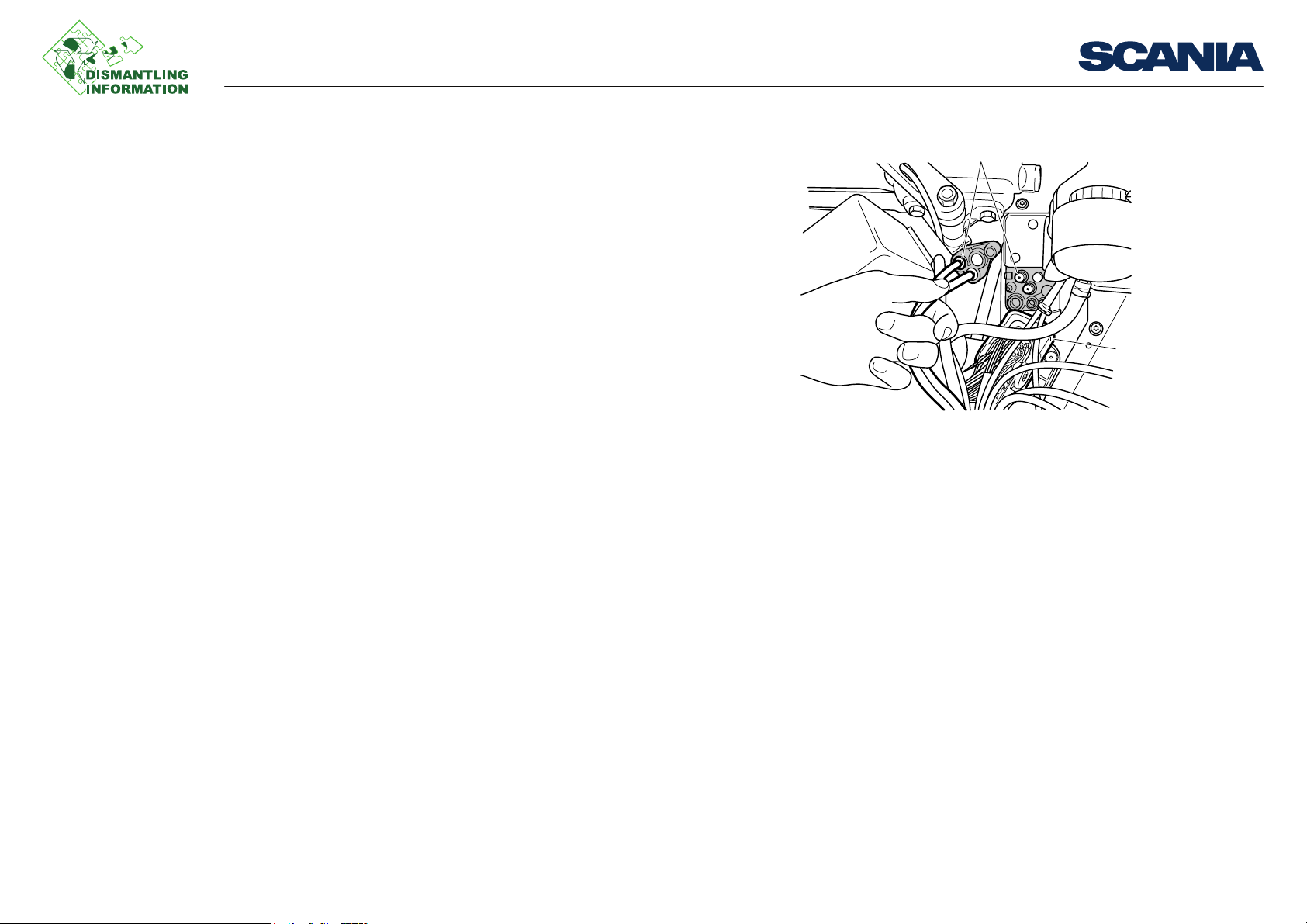
1. Compressed air circuit for accessory systems
2. Parking brake circuit
Work on the outside of the cab
1. Position the vehicle with the wheels in the straight ahead position.
2. Put the steering column in fully depressed position and tilt the steering wheel to-
wards the seat.
3. Disconnect all power sources from the vehicle.
4. Open the front grille panel and evacuate the air from the compressed air circuit
for accessory systems and the parking brake circuit.
Work description
03:19-00 Issue 1 en-GB 2 (13)
©
Scania CV AB 2012, Sweden
Page 3
Removing the instrument panel
2
1
201 917
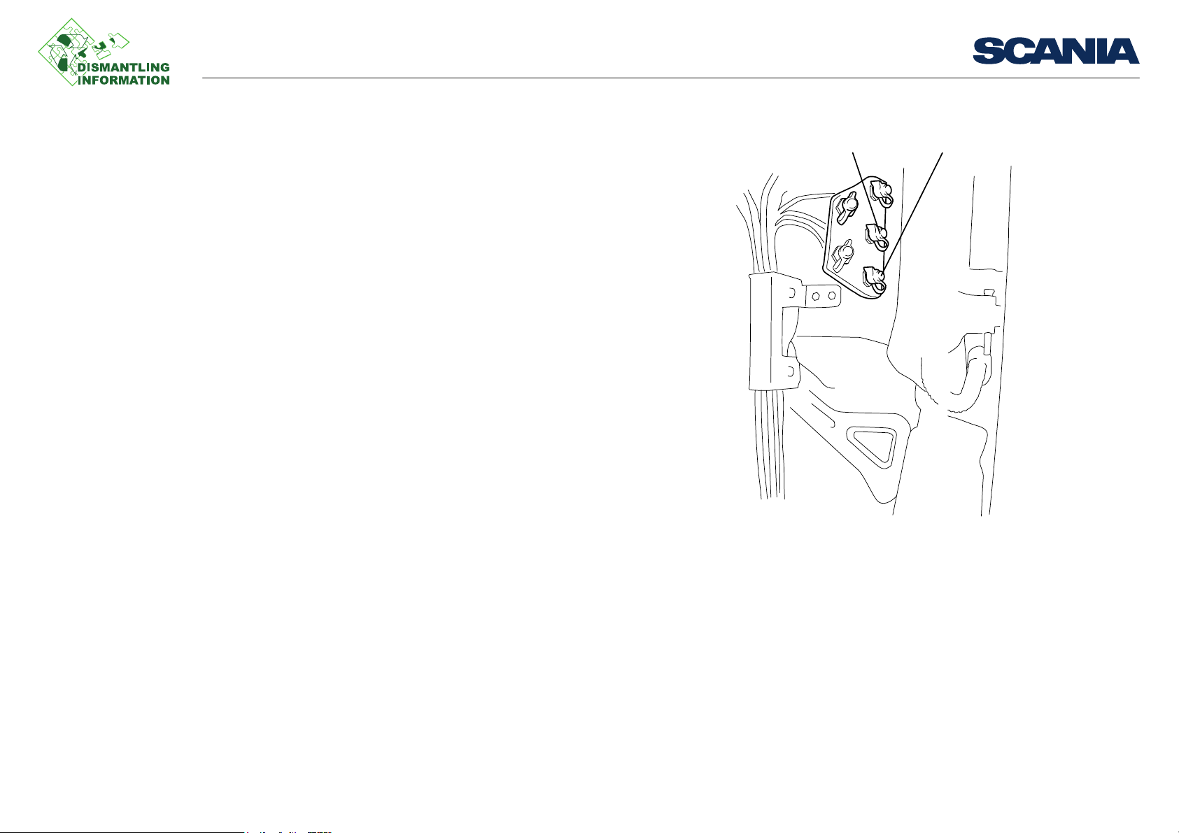
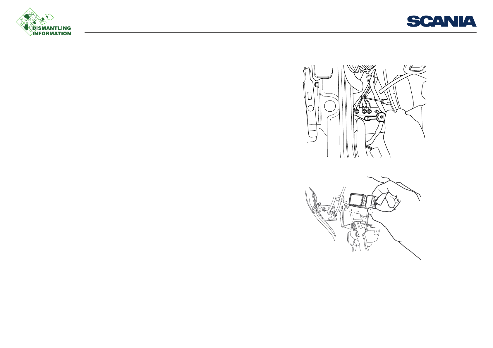
1. Block circuit coupling
2. Connector C1
5. Detach the 3 lower hoses in the block circuit coupling.
6. Remove the nuts and separate the block circuit coupling. Allow the outer half to
hang loose and press in the inner half in the firewall.
7. Undo connector C1 and press in the inner half in the firewall.
Work description
03:19-00 Issue 1 en-GB 3 (13)
©
Scania CV AB 2012, Sweden
Page 4
Removing the instrument panel
1
201 918
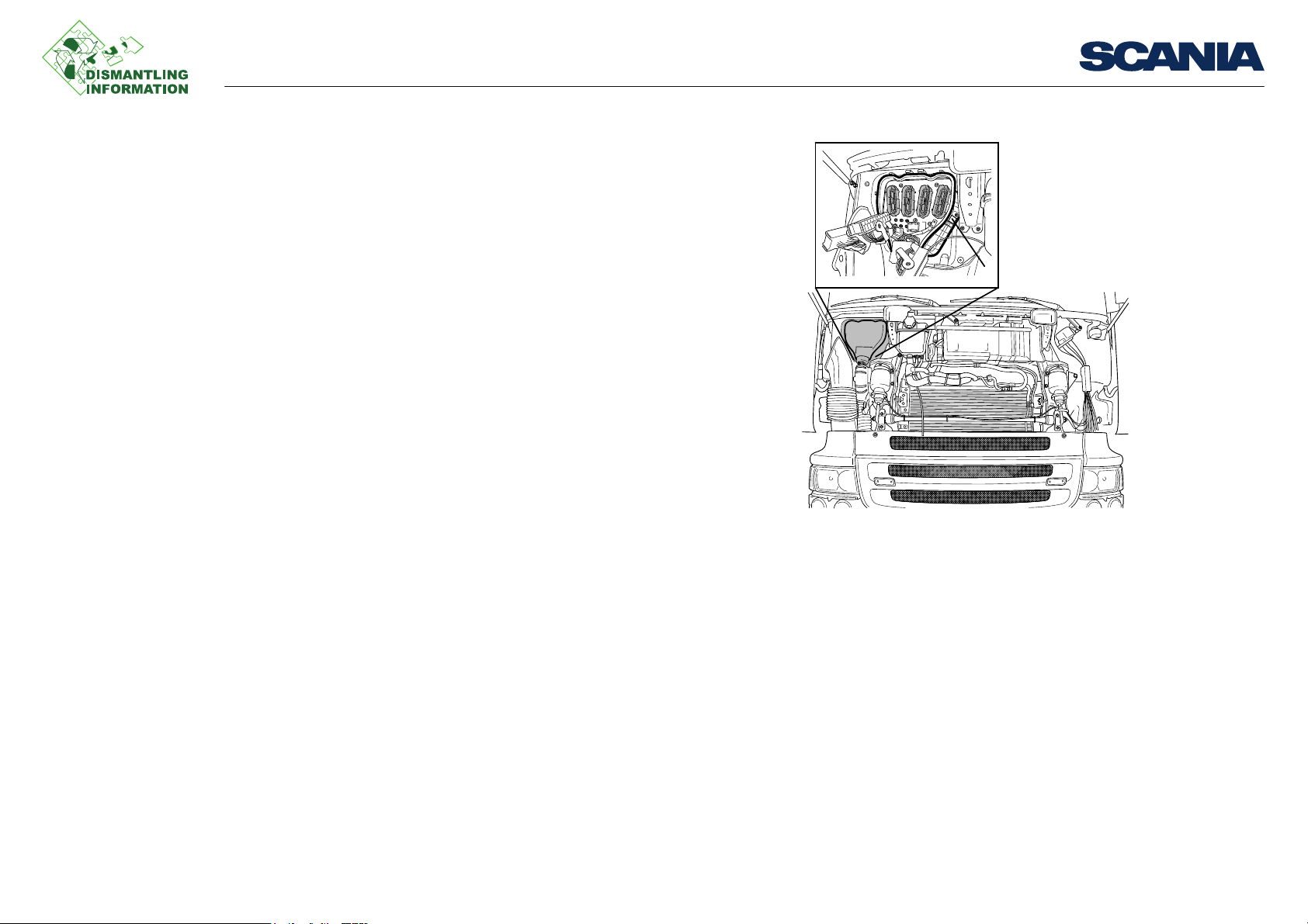
3. Remove the casing over the connectors on the firewall lead through and undo all
the connectors and other electrical cables. Remove the bezel from around the
cover.
Work description
03:19-00 Issue 1 en-GB 4 (13)
©
Scania CV AB 2012, Sweden
Page 5

Removing the instrument panel
200 826
Work inside the cab
Remove the parts below first:
1. Instrument panel lower panels and storage compartment in the centre.
2. Instrument panel side panels.
3. Panels on the door pillars and defroster panel below the windscreen.
Work description
03:19-00 Issue 1 en-GB 5 (13)
©
Scania CV AB 2012, Sweden
Page 6
Removing the instrument panel
201 920
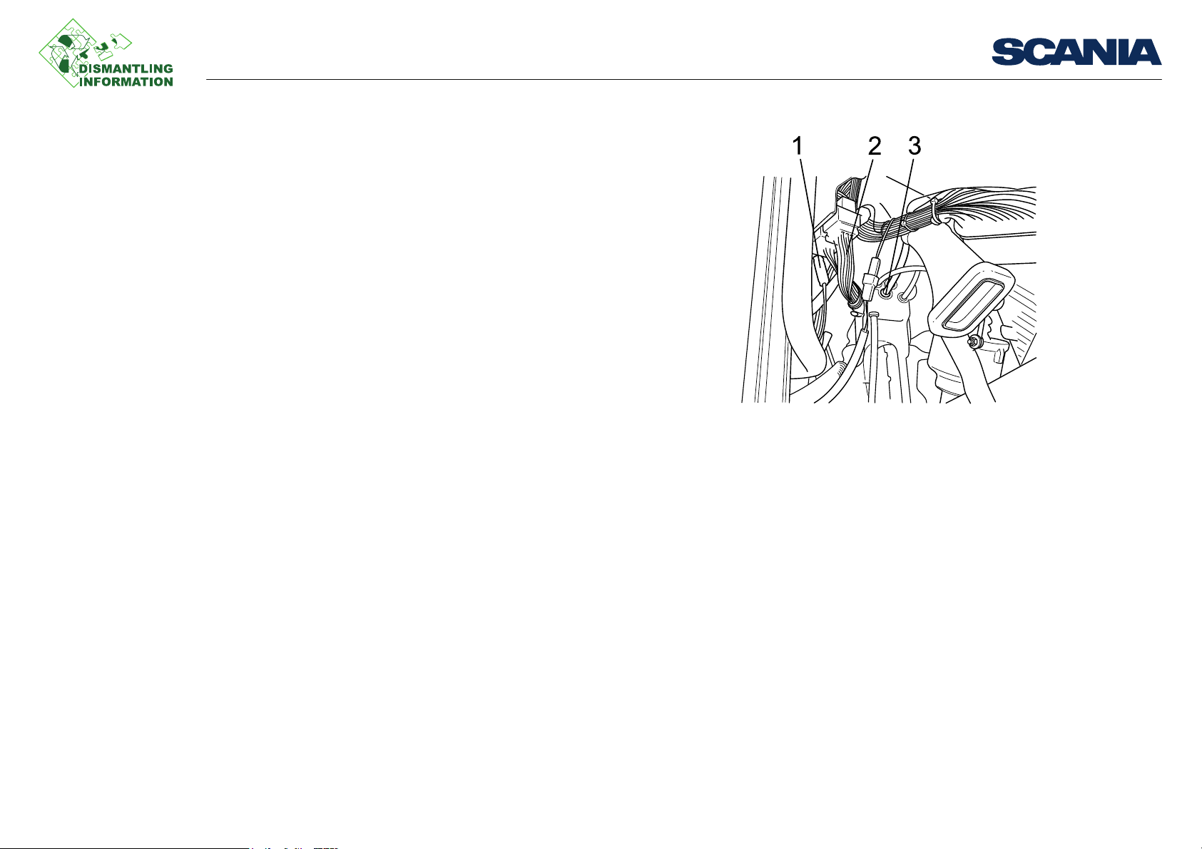
1. Coaxial cable
2. Door cable harness
3. Block circuit coupling
Then remove the parts below:
1. All removable hoses and electrical cables on the left-hand side of the cab.
Work description
03:19-00 Issue 1 en-GB 6 (13)
©
Scania CV AB 2012, Sweden
Page 7
Removing the instrument panel
201 919
201 513
2. Ground block.
3. Connectors for brake, accelerator and clutch sensors.
Work description
03:19-00 Issue 1 en-GB 7 (13)
©
Scania CV AB 2012, Sweden
Page 8

Removing the instrument panel
4. All connectors from the CUV control unit.
5. All connectors in the lower part of the central electric unit, cable harnesses to the
door connector and ground block, on the right-hand side of the cab.
6. Cable ties to the cable harness under the central electric unit.
7. All connectors.
Work description
03:19-00 Issue 1 en-GB 8 (13)
©
Scania CV AB 2012, Sweden
Page 9

Removing the instrument panel
201 559
Steering column
Remove the steering column in the order below:
1. Casings around the steering column.
2. Connectors.
3. Cable ties securing the cable harness.
4. Screw for the joint on the steering wheel shaft.
Work description
03:19-00 Issue 1 en-GB 9 (13)
©
Scania CV AB 2012, Sweden
Page 10

Removing the instrument panel
WARNING!
201 541
5. Separate the joint by pulling the lower steering wheel shaft downwards.
6. Remove the steering column 4 screws and lift out the steering column.
The steering column must not be carried or placed upside down. Risk for personal
injury if airbag is deployed.
Work description
03:19-00 Issue 1 en-GB 10 (13)
©
Scania CV AB 2012, Sweden
Page 11
Removing the instrument panel
201 921
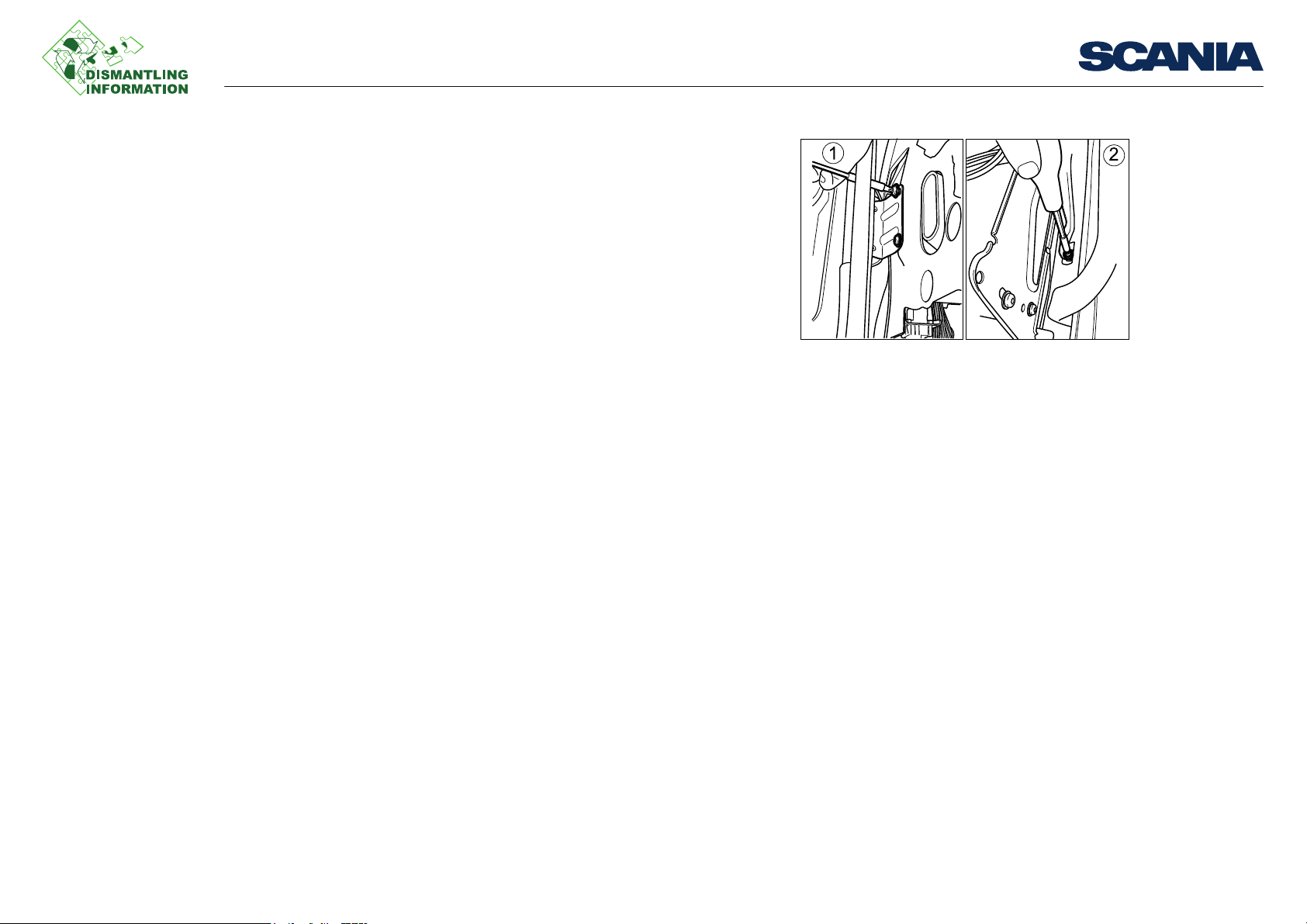
1. Metal bracket
2. Screws
Standard finishing operations
Remove the last parts in the order below:
1. All screws on the front edge of the instrument panel.
2. Metal brackets (1) on the short sides and screws (2) on the windscreen pillars.
Work description
03:19-00 Issue 1 en-GB 11 (13)
©
Scania CV AB 2012, Sweden
Page 12

Removing the instrument panel
202 053
3. Screws securing the crossmember to the cab structure.
Work description
03:19-00 Issue 1 en-GB 12 (13)
©
Scania CV AB 2012, Sweden
Page 13

Removing the instrument panel
201 922
1. Nuts
4. The instrument cluster and the 2 nuts securing the instrument panel to the steering
column attachment plate.
Finally, lift off the instrument panel.
Work description
03:19-00 Issue 1 en-GB 13 (13)
©
Scania CV AB 2012, Sweden
 Loading...