

Page 1
Removing the gearbox
General
Applies to gearboxes GR/S/O 875/895/9105/R.
Tools
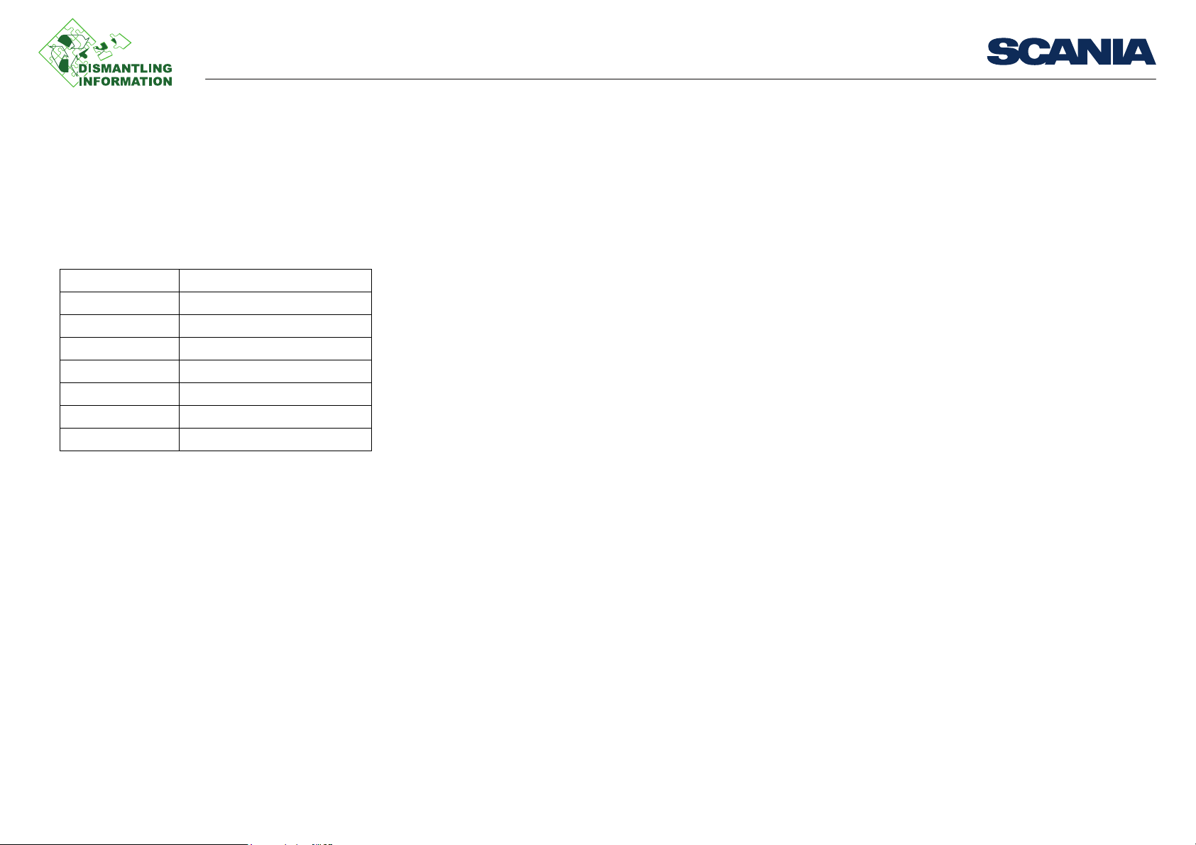
Examples of suitable tools from Scania:
Part number Designation
99 309 Turning tool
99 318 Engine support
99 502 Release bearing tool
99 544 Lifting tool for gearboxes
99 546 Lifting tool for gearboxes
587 313 Gearbox jack
587 500 Component hoist
General
03:67-00 Issue 1 en-GB 1 (16)
©
Scania CV AB 2012, Sweden
Page 2
Removing the gearbox
Draining the parking brake circuit.
Work description
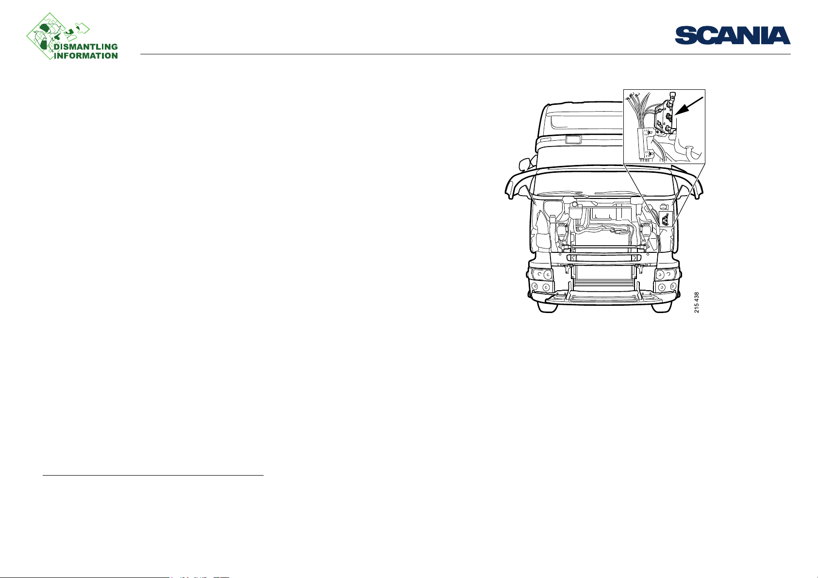
From above, vehicles with Opticruise
1. Drain the coolant.
2. Drain the parking brake circuit.
3. Tilt the cab.
4. Detach the oil pipes at the gearshift housing.
1
2
Work description
1. Vehicles with batteries at the far rear of the frame.
2. Vehicles with oil cooler.
03:67-00 Issue 1 en-GB 2 (16)
©
Scania CV AB 2012, Sweden
Page 3
Removing the gearbox
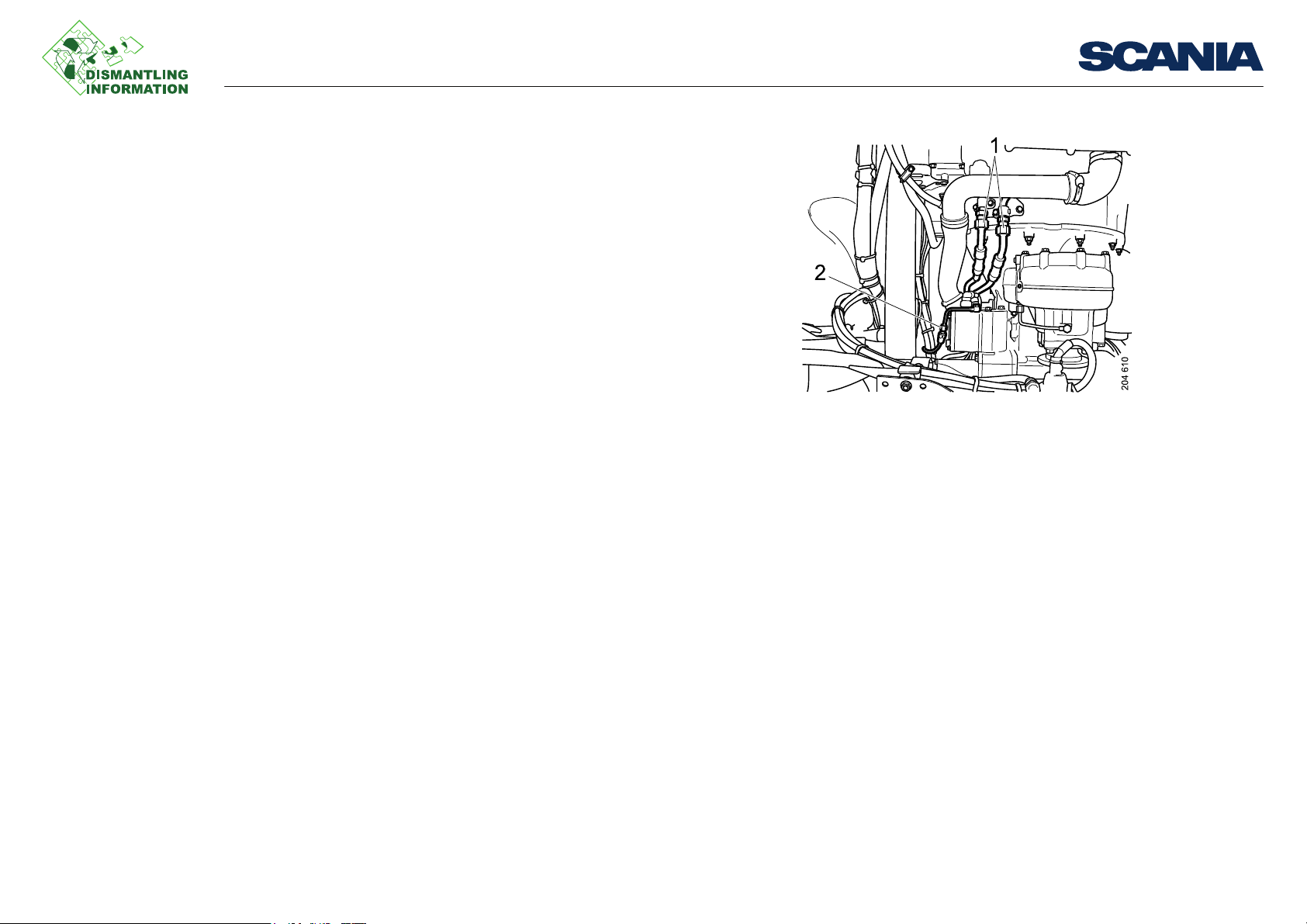
1. Oil pipe
2. Compressed air pipes
5. Detach the compressed air pipe at the gearshift housing.
6. Disconnect the cable interface in the left-hand side of the frame.
7. Undo the hose clamp on the upper retarder coolant hose.
8. Undo the 2 upper clutch servo screws.
9. Unscrew the 6 upper nuts for the clutch housing.
1
Work description
1. Vehicle with retarder.
03:67-00 Issue 1 en-GB 3 (16)
©
Scania CV AB 2012, Sweden
Page 4

Removing the gearbox
Draining the parking brake circuit
From above, vehicles without Opticruise
1. Drain the coolant.
2. Drain the parking brake circuit.
3. Tilt the cab.
1
Work description
1. Vehicles with batteries at the far rear of the frame.
03:67-00 Issue 1 en-GB 4 (16)
©
Scania CV AB 2012, Sweden
Page 5
Removing the gearbox
204 194
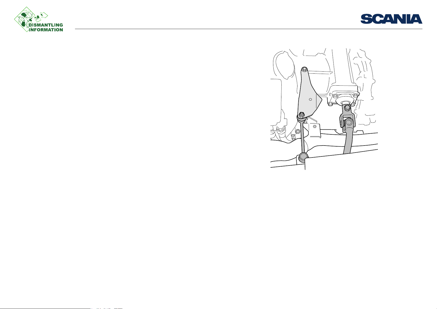
Torque rod and gear linkage
4. Detach the torque rod and gear linkage.
5. Undo the hose clamp on the upper retarder coolant hose.
Work description
1
1. Vehicle with retarder.
03:67-00 Issue 1 en-GB 5 (16)
©
Scania CV AB 2012, Sweden
Page 6

Removing the gearbox
1. Oil pipe
2. Compressed air pipes
Work description
6. Detach the oil cooler hoses and plug the oil pipes.
7. Undo the 2 upper clutch servo screws.
8. Unscrew the 6 upper nuts for the clutch housing.
1
1. Vehicles with oil cooler.
03:67-00 Issue 1 en-GB 6 (16)
©
Scania CV AB 2012, Sweden
Page 7

Removing the gearbox
204 037
Propeller shaft for EG pump.
Propeller shaft screws
From above, vehicles with Opticruise
1. Undo the exhaust system.
2. Remove the noise shields.
3. Detach the propeller shaft for the EG pump.
4. Undo the propeller shaft mounting at the centre joint.
5. Undo the 4 screws at the front of the propeller shaft and then use an M12 or M16
screw as a puller, depending on the size of the screw hole.
6. Detach the propeller shaft at the rear and lower the propeller shaft.
1
2
Work description
1. Vehicles with EG power take-off.
2. Vehicles with long chassis.
03:67-00 Issue 1 en-GB 7 (16)
©
Scania CV AB 2012, Sweden
Page 8

Removing the gearbox
Parking brake tank
Work description
7. Remove the compressed air connection for the parking brake tank which is locat-
ed behind the retarder. Remove the parking brake tank.
8. Undo the hydraulic pump.
1
1
.
1. Vehicles with dual-circuit steering.
03:67-00 Issue 1 en-GB 8 (16)
©
Scania CV AB 2012, Sweden
Page 9

Removing the gearbox
IMPORTANT!
204 229
Compressed air line to clutch servo
9. Detach the compressed air lines for the clutch servo. Then detach the clutch servo
and tie it onto the frame.
Hold the union when the compressed air line is unscrewed. Otherwise there is a risk
of damaging the clutch servo.
Do not disconnect the clutch fluid pipes.
10. Detach the electrical cables and the compressed air lines at the upper rear edge
of the gearbox.
Work description
03:67-00 Issue 1 en-GB 9 (16)
©
Scania CV AB 2012, Sweden
Page 10

Removing the gearbox
204 093
1
2
Work description
11. Drain the coolant from the retarder.
1
1. Vehicle with retarder.
03:67-00 Issue 1 en-GB 10 (16)
©
Scania CV AB 2012, Sweden
Page 11

Removing the gearbox
204 041
Upper coolant hose to retarder
Work description
12. Disconnect the upper retarder coolant hose.
1
03:67-00 Issue 1 en-GB 11 (16)
©
Scania CV AB 2012, Sweden
Page 12

Removing the gearbox
204 044
Remove two screws
204 045
Engine support 99 318
13. Fit engine supports 99 318 to support the engine. Two screws must be removed
from the oil sump before the engine supports can be fitted.
Work description
03:67-00 Issue 1 en-GB 12 (16)
©
Scania CV AB 2012, Sweden
Page 13

Removing the gearbox
1. Lock pin
2. Screw
204 039
Clutch bearing
14. Fit lifting tool 99 544 on the gearbox. Fit the lock pin (1) on the rear and then
screw on the two screws (2) on the front.
Then use component hoist 587 500 or gearbox jack 587 313 by fastening it to the
lifting tool.
15. Release the clutch bearing through the inspection hole using special tool 99 502
and press the clutch bearing forwards to make it release. A clicking sound should
be heard when the clutch bearing releases.
Work description
03:67-00 Issue 1 en-GB 13 (16)
©
Scania CV AB 2012, Sweden
Page 14

Removing the gearbox
204 046
Gearbox beam screws
16. Lift the gearbox a little and remove the gearbox beam screws.
17. Lower the engine and gearbox so that the engine rests on the engine supports.
18. Undo the lower clutch housing nuts and remove the gearbox.
Work description
03:67-00 Issue 1 en-GB 14 (16)
©
Scania CV AB 2012, Sweden
Page 15

Removing the gearbox
Parking brake tank
From below, vehicles without Opticruise
1. Undo the exhaust system.
2. Detach the noise shields.
3. Detach the propeller shaft for the EG pump.
4. Undo the propeller shaft mounting at the centre joint.
5. Undo the 4 screws at the front of the propeller shaft and then use an M12 or M16
screw as a puller, depending on the size of the screw hole.
6. Detach the propeller shaft at the rear and lower the propeller shaft.
7. Remove the compressed air connection for the parking brake tank which is locat-
ed behind the retarder. Remove the parking brake tank.
8. Undo the hydraulic pump.
9. Detach the compressed air lines for the clutch servo. Then detach the clutch servo
3
and tie it onto the frame.
10. Drain the coolant from the retarder.
11. Disconnect the upper retarder coolant hose.
12. Fit engine supports 99 318 to support the engine. Two screws must be removed
4
from the oil sump before the engine supports can be fitted.
13. Fit lifting tool 99 544 on the gearbox. Fit the lock pin 1 on the rear and then screw
on the two screws 2 on the front.
Then use component hoist 587 500 or gearbox jack 587 313 by fastening it to the
lifting tool.
14. Release the clutch bearing through the inspection hole using special tool 99 502
and press the clutch bearing forwards to make it release. A clicking sound should
be heard when the clutch bearing releases. Use special tool 99 309 if the engine
needs to be turned.
15. Lift the gearbox a little and remove the gearbox beam screws.
1
2
1
.
4
Work description
1. Vehicles with EG power take-off.
2. Vehicles with long chassis.
3. Vehicles with dual-circuit steering.
4. Vehicle with retarder.
03:67-00 Issue 1 en-GB 15 (16)
©
Scania CV AB 2012, Sweden
Page 16

Removing the gearbox
Note:
Lifting tool
16. Lower the engine and gearbox so that the engine rests on the engine supports.
17. Undo the lower clutch housing nuts and remove the gearbox.
If the gearbox is to be transported with the aid of an overhead hoist, lifting tool 99
546 must be used. Lifting the gearbox in the input shaft will damage the input shaft
bearing.
Work description
03:67-00 Issue 1 en-GB 16 (16)
©
Scania CV AB 2012, Sweden
 Loading...