


D512 PCL PROGRAMMING MANUAL
PN: 9001180B

SATO America, Inc.
10350A Nations Ford Road
Charlotte, NC 28273
Main Phone: (704) 644.1650
Technical Support: (704) 644.1660
Technical Support Fax: (704) 644.1661
E-Mail: satosales@satoamerica.com
techsupport@satoamerica.com
www.satoamerica.com
Copyright 2008 SATO America, Inc.
All rights reserved
WARNING
THE EQUIPMENT REFERENCED IN THIS DOCUMENT COMPLIES WITH THE REQUIREMENTS IN PART 15
OF FCC RULES FOR A CLASS B COMPUTING DEVICE. OPERATION OF THIS EQUIPMENT IN A
RESIDENTIAL AREA MAY CAUSE UNACCEPTABLE INTERFERENCE TO RADIO AND TV RECEPTION.

Table of Contents
PCL Emulation
PCL Emulation ........................................................................................................................ 1-2
Selecting PCL Emulation ...................................................................................................................... 1-2
Page Formatting ................................................................................................................................... 1-3
Font and Symbol Set Support............................................................................................................... 1-4
Command Structure.............................................................................................................................. 1-6
Command Structure.............................................................................................................................. 1-7
PCL Emulation Commands .................................................................................................................. 1-9
GL/2 Commands................................................................................................................................. 1-27
Raster Image Graphics....................................................................................................................... 1-30
Macros ................................................................................................................................................ 1-38
Printer Job Language
Printer Job Language.............................................................................................................. 2-2
PJL Command Notation........................................................................................................................ 2-2
Kernel Commands ................................................................................................................................ 2-3
Job Separation Commands .................................................................................................................. 2-4
Environment Commands and Variables ............................................................................................... 2-7
Status Readback Commands ............................................................................................................. 2-12
Status Message Format...................................................................................................................... 2-18
PCL Support
PCL Support............................................................................................................................ 3-2
PJL Support
Printer Job Language Support ................................................................................................ 4-2
Barcode Commands
Bar code Commands............................................................................................................... 5-2
Two-dimensional bar codes.................................................................................................................. 5-5
Printer Language Change Commands
Setting the Printer to SBPL Language .................................................................................... 6-2
Setting the Printer to PCL Language....................................................................................... 6-2
SATO Contacts
SATO Group of Companies .................................................................................................... 7-2
SATO D512 PCL PROGRAMMING MANUAL PN: 9001180B

PN: 9001180B SATO D512 PCL PROGRAMMING MANUAL

1PCL EMULATION
• Selecting PCL Emulation
• Page Formatting
• Font and Symbol Set Support
• Command Structure
• PCL Emulation Commands
• GL/2 Commands
• Raster Image Graphics
•Macros
SATO D512 PCL Programming Manual Page 1-1

Unit 1: PCL Emulation
PCL EMULATION
The D512 printer supports the Hewlett-Packard Company’s LaserJet Printer Command
Language. This chapter discusses PCL emulation commands, along with resident PCL
emulation font and symbol set support.
To determine which commands your printer supports, see Section, “PCL Support.”
SELECTING PCL EMULATION
USING YOUR SOFTWARE PROGRAM
The D512 requires a PJL prologue, or series of commands, at the start of each print job,
including the Printer Job Language (PJL) Enter Language Command. See “ENTER LANGUAGE
Command” in Printer Job Language section for more information. See “Printer Job Language” in
the Printer Job Language section for the syntax and use of PJL. An example of a well-structured
PJL prologue would be the following:
esc
[
]%-12345X
@PJL SET LCUSTOMPAPERUNITS=INCHES
@PJL SET LCUSTOMPAPERHEIGHT=6
@PJL SET LCUSTOMPAPERWIDTH=4
@PJL SET RESOLUTION=300
@PJL ENTER LANGUAGE=PCL
Page 1-2 SATO D512 PCL Programming Manual

Unit 1: PCL Emulation
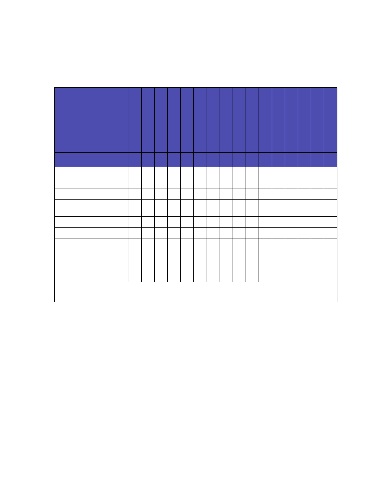
PAGE FORMATTING
The printable areas and logical pages for PCL emulation (both portrait and landscape
orientation) are illustrated below. See the Legend that follows for definitions of areas A through I.
P
RINTABLE AREAS
Legend:
A Portrait physical page width and landscape physical page length
B Portrait physical page length and landscape physical page width
C Portrait logical page width
D Landscape logical page width
E Distance between the side edge of the physical page and the logical
page in portrait
F Distance between the side edge of the physical page and the logical
page in landscape
G Distance between the top and bottom edge of the physical page and
logical page
H Distance between the left and right edge of the physical page and the
printable area in portrait, or distance between the top and bottom edge
of the physical page and printable area in landscape
I Distance between the top and bottom edge of the physical page and the
printable area in portrait, or distance between the left and right edge of
the physical page and the printable area in landscape
SATO D512 PCL Programming Manual Page 1-3

Unit 1: PCL Emulation
FONT AND SYMBOL SET SUPPORT
Your printer has 10 resident scalable PCL fonts.
Several parameters are used to select a font from the data stream. These include symbol set,
spacing, point, or pitch, style, weight, and typeface number. For scalable fonts, you can vary the
size of a font by specifying pitch or point size (point size for proportional fonts, pitch for fixed
space fonts.
A symbol set defines which characters are available for a font and the code point for each of
these characters. Your printer supports 16 resident symbol sets. The table beginning on page
1-5 shows the symbol sets available for each font in PCL emulation. Not all fonts support all
symbol sets.
S
TANDARD PCL EMULATION FONTS
The following table lists the parameters to be used in the font selection commands for each of
the10 standard PCL emulation fonts.
Table 1-1: Forward and Backward Compatibility Font Selection Commands
Forward and Backward Compatibility Mode
Standard PCL Emulation Font Name
Courier Regular 0 0 0 4099
Univers Medium 1 0 0 4148
Univers Bold 1 0 3 4148
CG Triumvirate Condensed Bold 1 4 3 4100
Roman Pillar Regular 0 0 0 30211
Roman Pillar Italic 0 1 0 30211
Roman Pillar Bold 0 0 3 30211
Roman Pillar Bold Italic 0 1 3 30211
OCR-A 0 0 0 23584
OCR-B 0 0 0 23590
Spacing Style Wei ght Typ ef ace
Page 1-4 SATO D512 PCL Programming Manual
Unit 1: PCL Emulation
SELECTING SYMBOL SETS FOR THE SATO D512
To determine if a font or typeface supports a symbol set, see the complete listing of PCL
emulation fonts and symbol sets in the table below.
Table 1-2: PCL Emulation Symbol Sets
Typeface / Symbol Set
Symbol Set ID
Courier Regular
Univers Medium
Univers Bold
CG Triumvirate Condensed
Bold
Roman Pillar Regular
Roman Pillar Italic
Roman Pillar Bold
Roman Pillar Bold Italic
OCR-A
OCR-B
Indicates Typeface supports the specified Symbol Set.
US Ascii (0U)
Windows Latin 1 (19U)
Windows Latin 1 (9E)
Windows Latin 1 (5T)
Windows Latin 1 (19L)
Windows Cyrillic (9R)
0U
19U
9E
5T
19L
9R
Indicates Typeface does not support the specified Symbol Set.
Windows Greek (9G)
9G
ISO8859-1 (0N) (Latin 1)
ISO8859-2 (2N) (Latin 2)
0N
2N
ISO8859-9 (5N) (Latin 5)
ISO8859-10 (6N) Latin 6)
5N
6N
ISO8859-5 (10N) Cyrillic)
Roman 8 (8U)
10N
8U
IBM CP850 (12U)
12U
OCR-A (0O)
0O
OCR-B (1O)
1O
SATO D512 PCL Programming Manual Page 1-5

Unit 1: PCL Emulation
COMMAND STRUCTURE
This section introduces the different types of PCL emulation commands and their structure, or
syntax. It also demonstrates how you can link commands to abbreviate them.
C
ONTROL CODES
Control Codes are single-character instructions.
Table 1-3: Control Codes
Code Dec Hex Function Result
BS 8 08 Backspace Moves the cursor toward the left margin one horizontal space equal to the
last printed character
HT 9 09 Horizontal Tab Moves the cursor to the next defined tab stop
LF 10 0A Line Feed Advances the cursor to the same horizontal position on the following line as
determined by either the Vertical Motion Index (VMI) or Set Line Spacing
command
FF 12 0C Form Feed Advances the cursor to the same horizontal position at the top margin of the
next page
CR 13 0D Carriage Return Moves the cursor to the left margin
SP 32 20 Space Moves the cursor to the right one column
SI 15 0F Primary Font Selects the primary font
SO 14 0E Secondary Font Selects the secondary font
OMMANDS
C
PCL commands are multibyte strings (also known as “escape sequences”) that begin with the
Escape control code (
ESC
, ¬, decimal 27, or hexadecimal 1B). The
ESC
control code notifies the
printer that the characters that follow are to be interpreted as part of a command and are not
control codes or data to be printed.
Page 1-6 SATO D512 PCL Programming Manual

Unit 1: PCL Emulation
COMMAND STRUCTURE
Most PCL emulation commands have the following structure:
ESC
& a # C
Spaces have been added to this example for readability. The command parameter variables are
indicated by a number sign (#).
Table 1-4: Description of Command Structure
Element Description
ESC
& Parameterized character from American National Standard Code for Information
a Group character from ASCII table (ranging from 96 to 126 decimal) that specifies a
# Decimal character string value within specified numeric ranges; may be preceded by a +
Decimal 27 or hex 1B
Interchange (ASCII) table (ranging from 33 to 47 decimal)
group type of control
or - sign and contain a decimal point
C Termination character from ASCII table (ranging from 64 to 94 decimal)
C
OMMAND PARAMETERS
A command parameter sets the value for a command. This value stays constant until either a
different value resets the command or a command resets the printer to the default values. For
example, after the printer receives a command that selects a right margin beginning at column
63, the right margin of each printed page begins at column 63. That margin stays constant until a
right margin command with a different value resets it or until the printer is reset.
Parameters for each command are listed in the command tables beginning on page 9. Use the
Symbol Set Tables to determine the decimal or hexadecimal value for each parameter. To
determine a decimal or hex value, first locate the value of the parameter you require in the
Symbol Set Table. The decimal value is the value shown in the bottom of the cell or box with that
parameter. To find a hex value, go straight up the grid from the desired parameter and read the
value in the top heading. This is the first character of the hex value. Next, go straight across the
grid to the left of the parameter and read the value in the left column heading. This is the second
character of the hex value. For example,
ESC
(¬) is coded 1B in Hex and 27 in decimal. (Any one
of the three values ¬, 1B, or 27 might be used in your application. Read your documentation to
determine which to use.) The example sets the pitch of the primary font to16.66 characters per
inch.
Example:
ESC
(s16.66H
•Decimal: 27 40 115 49 54 46 54 54 72
•Hex: 1B 28 73 31 36 2E 36 36 48
SATO D512 PCL Programming Manual Page 1-7

Unit 1: PCL Emulation
Use the plus symbol (+) or the minus symbol (-) to select a position relative to the current cursor
position. For example:
ESC
&a6C Move to horizontal cursor position, column six
ESC
&a+6C Move six columns to the right of the current position
ESC
&a-6C Move six columns to the left of the current position
L
INKING COMMANDS
You can combine PCL emulation commands by linking them if the first 3 bytes of the commands
are identical. The combined, short form sends the first 3 bytes only once in the string. To
combine commands:
• Use the first 3 bytes (characters) of the command only once at the
start of the command string.
• Make the last letter of each command in the string lowercase.
• Capitalize the last letter of the string.
For example, notice that the first 3 bytes of these two commands are the same:
ESC
(s10H Select 10 characters per inch
ESC
(s4099T Select Courier typeface
To combine these two commands, use this form:
ESC
(s10h4099T
which is 3 bytes shorter than the long form:
ESC
(s10H
ESC
(s4099T
You can combine more than two commands; for example, you can add Select Stroke Weight
ESC
Bold (
(s3B) to the previous two commands:
ESC
(s10h3b4099T
or in the long form:
ESC
(s10H
ESC
(s3B
ESC
(s4099T
Page 1-8 SATO D512 PCL Programming Manual

Unit 1: PCL Emulation
PCL EMULATION COMMANDS
See the following tables for a listing of the commands grouped by function.
To determine which commands your printer supports, see “Table 3-1: PCL Emulation
Commands” in the PCL Support section.
PCL E
MULATION COMMANDS BY FUNCTION
Table 1-5: Job Control
Command / Parameters Function / Result
ESC
E Printer Reset
-
• Prints any partial pages.
• Resets printer environment to defaults.
• Deletes all temporary downloaded resources.
ESC
&d#A
0 = Collation off
1 … 999 (number of Copies)
ESC
&l#X
# = number of Copies (1 to 32767)
Default = 1
ESC
&l#S Simplex/Duplex Print
ESC
&l#U
# = number of Decipoints
Range = -32767 to 32767
(1 Decipoint = 1/720 inch)
Default = 0
ESC
&l#Z
# = number of Decipoints
Range = -32767 to 32767
(1 Decipoint = 1/720 inch)
Default = 0
Number of Collated Copies
Turns collation of pages off or sets the number of collated copies.
Number of Copies
Affects the page currently in process and subsequent pages.
This command is parsed and ignored.
Long-Edge Offset Registration
Also known as Left Offset.
Adjusts placement of logical page along the width of the physical page.
Short-Edge Offset Registration
Also known as Top Offset.
Adjusts placement of logical page along the length of the physical page.
SATO D512 PCL Programming Manual Page 1-9

Unit 1: PCL Emulation
Table 1-5: Job Control (continued)
Command / Parameters Function / Result
ESC
&u#D
Range = 300
ESC
% – 12345X Universal Exit Language (UEL) / Start of PJL
Unit of Measure
Sets the size for the PCL Unit (units per inch).
The Unit of Measure defines the unit used in the following commands:
• Horizontal Cursor Position by PCL Unit (
• Vertical Cursor Position by PCL Unit (
• Horizontal Rectangle Size by PCL Unit (
• Vertical Rectangle Size by PCL Unit (
The Unit of Measure also affects the rounding of character escapements
and the Horizontal Motion Index.
Note: This command does not affect the interpretation of binary raster
data for bitmapped fonts, raster graphics, or user defined fill patterns.
This command terminates the current printer language and allows
switching into PJL. For more information, see “UNIVERSAL EXIT
LANGUAGE Command” in Section 2, Printer Job Language.
ESC
ESC
ESC
*p#X)
*p#Y)
ESC
*c#A)
*c#B)
Table 1-6: Page Control
Command / Parameters Function / Result
ESC
&l#A Set Page Size
This command is parsed and ignored.
ESC
&l#H Paper Source
This command is parsed and ignored.
ESC
&f#G Set Universal Width
This command is parsed and ignored.
ESC
&f#F Set Universal Height
This command is parsed and ignored.
ESC
&f#O Set Universal Feed Direction
This command is parsed and ignored.
ESC
&f#W [custom name]
# = number of bytes in the custom name
ESC
&l#O
0 Portrait (Default)
1 Landscape
2 Reverse Portrait
3 Reverse Landscape
ESC
&a#P
# = Degrees (0, 90, 180, 270)
Default = 0
Set Universal Custom Name
This command is parsed and ignored.
Select Orientation
Specifies the position of the logical page with respect to the physical
page.
Note: This setting resets margins, the number of printable lines per page,
and the cursor position.
Print Direction
Rotates the coordinate system counter-clockwise in 90° increments with
respect to the current orientation.
Note: Margins are not rotated or cleared.
Page 1-10 SATO D512 PCL Programming Manual

Unit 1: PCL Emulation
Table 1-6: Page Control (continued)
Command / Parameters Function / Result
ESC
&c#T
0 Horizontal Printing
-1 Vertical Rotated Printing
ESC
&a#L
# = Column
Default = 0
ESC
&a#M
# = Column
Default = Logical Page Width
ESC
9 Clear Horizontal Margins
ESC
&l#E
# = number of lines
Default = 3 (1/2 inch)
ESC
&l1T Job Separation
ESC
&l#F
# = number of lines
Default = 60 or 64 (Country specific)
ESC
&l#G Set Output Bin
ESC
&l#L
0 Off
1 On (Default)
ESC
&k#H
# = number of 1/120 inch increments
(Valid to 4 decimal places)
ESC
&l#C
# = number of 1/48 inch increments
(Valid to 4 decimal places)
Default = 8
Character Text Path Direction
Vertically rotates text for use in vertical writing, such as printing
Japanese text.
Set Left Margin
Sets the left margin to the left edge of the designated column.
Note: The column width is defined by the space character of the active
font and the Horizontal Motion Index (HMI).
Set Right Margin
Sets the right margin to the right edge of the designated column.
Note: The column width is defined by the space character of the active
font and the HMI.
Clears left and right margins.
Set Top Margin
Sets the number of lines between the top of the physical page and first
line of print. Line height is determined by the current Vertical Motion
Index (VMI) and/or line spacing value.
Note: Setting a top margin of 0 results in the first line of text falling
outside of the printable area.
This command is parsed and ignored.
Set Text Length
Sets the bottom margin length in lines, measured from the first line of the
page.
Text Length equals Logical Page Length –1 inch (–1/2 inch for top and –
1/2 inch for bottom).
This command is parsed and ignored.
Skip Perforation
Perforation area includes the area from the bottom margin of the current
page to the top margin of the next page. When skipping perforations, a
line feed past the bottom margin ejects a page and places the cursor at the
top margin of the next page.
Set Horizontal Motion Index (HMI)
Sets the width of all characters for fixed-space fonts. Sets only the width
of the space for proportional spaced fonts.
Set Vertical Motion Index (VMI)
Sets Vertical Motion Index in 1/48 inch increments. The VMI determines
the vertical distance between lines.
Notes:
• Use of this command alters any previous Set Line Spacing command
settings.
SATO D512 PCL Programming Manual Page 1-11

Unit 1: PCL Emulation
Table 1-6: Page Control (continued)
Command / Parameters Function / Result
ESC
&l#D
1 1 line/inch
22 lines/inch
33 lines/inch
44 lines/inch
6 6 lines/inch (Default)
88 lines/inch
12 12 lines/inch
16 16 lines/inch
24 24 lines/inch
48 48 lines/inch
E
SC
&a#G Duplex Page Side Selection
ESC
&l#P
# = number from 0 to 14
0 = default page length is used
(1 to 14 = new page length is set)
ESC
&k#W Text Scale Mode
Set Line Spacing (Alternative Method)
Specifies VMI in lines per inch.
Notes:
• Unsupported values are ignored.
• Use of this command alters any earlier VMI setting.
This command is parsed and ignored.
Set Page Length
Sets the logical page length in number of lines.
Notes:
• This command is sent at the beginning of a page in a print job and
prior to any printable data.
• When the command is sent, the current page is closed and printed.
• Unsupported values are ignored.
This command is parsed and ignored.
Page 1-12 SATO D512 PCL Programming Manual

Unit 1: PCL Emulation
Table 1-7: Cursor Positioning
Command / Parameters Function / Result
ESC
&a#C
# = number of Columns
ESC
&a#H
# = number of Decipoints
1
1
(1 Decipoint = 1/720 inch)
ESC
*p#X
# = number of PCL Units
ESC
&a#R
# = number of Rows
ESC
&a#V
# = number of Decipoints
1
1
1
(1 Decipoint = 1/720 inch)
ESC
*p#Y
# = number of PCL Units
ESC
= Half Line-Feed
ESC
&k#G
1
0 CR=CR, LF=LF, FF=FF (Default)
1 CR=CR+LF, LF=LF, FF=FF
2 CR=CR, LF=CR+LF, FF=CR+FF
3 CR=CR+LF, LF=CR+LF,
FF=CR+FF
ESC
&f#S
0 Push
1 Pop
1
Parameter preceded by + or - sign denotes a relative cursor move from the current cursor position. Parameter without a sign
denotes an absolute cursor move from the top left margin.
Horizontal Cursor Position (in Columns)
Moves the cursor to a new position along the horizontal axis.
Note: The column width is determined by the space character width of the
active font or the Horizontal Motion Index (HMI), if set.
Horizontal Cursor Position (in Decipoints)
Moves the cursor to a new position along the horizontal axis.
Horizontal Cursor Position (in PCL Units)
Moves the cursor to a new position along the horizontal axis.
Note: PCL units are set by the Unit-of-Measure Command.
Vertical Cursor Position (in Rows)
Moves the cursor to a new position along the vertical axis.
Note: Row height is determined by either the Vertical Motion Index (VMI) or
the Set Line Spacing Command.
Vertical Cursor Position (in Decipoints)
Moves the cursor to a new position along the vertical axis.
Vertical Cursor Position (in PCL Units)
Moves the cursor to a new position along the vertical axis.
Note: PCL units are set by the Unit-of-Measure Command.
Moves the cursor down 1/2 line (1/2 of the current VMI).
Set Line Termination
Controls how the printer responds to the Carriage Return (CR), Line Feed
(LF), and Form Feed (FF) control codes.
Push / Pop Cursor Position
Sets up a cursor position stack for storing and recalling various cursor
positions. The stack can store up to 20 cursor positions.
SATO D512 PCL Programming Manual Page 1-13

Unit 1: PCL Emulation
Note: For the commands listed in the following table, font selection is based on all
parameters set following the best fit selection rules.
Table 1-8: Font Selection
Command / Parameters Function / Result
ESC
(# (primary)
ESC
)# (secondary)
# = symbol set ID
ESC
(s#P (primary)
ESC
)s#P (secondary)
0 Fixed (Default)
1 Proportional
ESC
(s#H (primary)
ESC
)s#H (secondary)
# = characters per inch
Default = 10
ESC
(s#V (primary)
ESC
)s#V (secondary)
# = height in points (.25 to 999.75)
Default = 12
ESC
(s#S (primary)
ESC
)s#S (secondary)
0 Upright (Default)
1 Italic
4 Condensed
5 Condensed Italic
8 Compressed
24 Expanded
32 Outline
64 Inline
128 Shadowed
160 Outline Shadowed
Select Symbol Set
See Table 9-2 for the symbol sets which are supported.
Select Spacing
Selects a font with proportional or fixed spacing.
Select Pitch
Selects the number of characters per inch (cpi) for a fixed-space
bitmapped or monospaced scalable font. Valid to 2 decimal places.
Note: Pitch is not needed for proportional spaced fonts.
Height (Select Point Size)
Sets the font height in points. Valid to 2 decimal places.
Note: Point size is not needed for monospaced fonts. For fonts larger
than 12 points, it may be necessary to change the line spacing.
Select Style
Identifies the physical traits of a character and the composition of the
font symbols.
Note: You can only use this command to select fonts currently available
in the printer. It cannot alter the appearance of the available fonts.
Page 1-14 SATO D512 PCL Programming Manual
Unit 1: PCL Emulation
Table 1-8: Font Selection (continued)
Command / Parameters Function / Result
ESC
(s#B (primary)
ESC
)s#B (secondary)
-7 Ultra Thin
-6 Extra Thin
-5 Thin
-4 Extra Light
-3 Light
-2 Demi Light
-1 Semi Light
0 Medium (Default)
1 Semi Bold
2 Demi Bold
3 Bold
4 Extra Bold
5 Black
6 Extra Black
7 Ultra Black
ESC
(s#T (primary)
ESC
)s#T (secondary)
# Typeface identifier (0 - 65535)
Select Stroke Weight
Selects a font with a particular thickness.
Note: This command will not alter the stroke weight of an available font.
See Table1 in this section “Forward and Backward Compatibility Font
Selection Commands” for the stroke weight variations available for the
resident fonts.
Select Typeface
Selects the best fit font design.
Note: For a list of typeface numbers, see Table 1 in
this section: “Forward and Backward Compatibility
Font Selection Commands.” See “Font and Symbol
Set Support” on page 4.
ESC
(#X (primary)
ESC
)#X (secondary)
Select Font by Font ID
Selects the font by the identification number.
# = Font ID (0 - 32767)
ESC
(3@ (primary)
ESC
)3@ (secondary)
ESC
&p#X[data]
# = number of data of bytes to print as text
Select Default Font
Sets all font selection characteristics to the Default Font.
Transparent Print Data
This command is only supported when used to enter data to be encoded
in a Maxicode barcode.
ESC
&d#D
0,1 Fixed
2 Fixed - double
3Floating
4 Floating - double
Select Underline Type (Enable)
Notes:
• Fixed underline is drawn 5 pels below cursor position.
• Floating underline position is determined by all the positions of the
characters with descenders in the fonts that are to be underlined.
• Underline thickness is 1/100 inch. Double underline is not supported
and will be printed as a single underline.
ESC
&d@ Underline - Disable
SATO D512 PCL Programming Manual Page 1-15

Unit 1: PCL Emulation
Table 1-8: Font Selection (continued)
Command / Parameters Function / Result
ESC
&t#P
0, 1 1 byte characters
21 1 or 2 byte characters
31 1 or 2 byte characters
Text Parsing Method
Communicates to the PCL parser whether character codes are interpreted
as 1-byte or 2-byte character codes. This command is parsed and
ignored.
38 1 or 2 byte characters
1008 1, 2, or 3 byte characters (UTF-8)
ESC
&k#S
0 10.00 cpi
Select Primary and Secondary Pitch
Selects the pitch for the primary and secondary font.
2 16.66 cpi
4 12.00 cpi
Table 1-9: User-Defined Symbol Set
Command / Parameters Function / Result
ESC
*c#R
# = Symbol Set ID (0 - 32767)
Default = 0
ESC
(f#W[data]
# = number of data bytes
ESC
*c#S
0 Delete all (temporary and permanent)
1 Delete all temporary
2 Delete current (ID)
4 Make current temporary
5 Make current permanent
Symbol Set ID Code
Sets the symbol set identification for the symbol set downloaded.
Define Symbol Set
Contains the data for the user-defined symbol sets.
Symbol Set Control
Manages user-defined symbol sets.
Page 1-16 SATO D512 PCL Programming Manual

Unit 1: PCL Emulation
Table 1-10: Font Creation
Command / Parameters Function / Result
ESC
*c#D
# = Font ID # (0 - 32767)
Default = 0
ESC
)s#W[data]
# = number of data bytes
ESC
*c#F
0 Delete all (temporary and permanent)
1 Delete all temporary
2 Delete previous font ID
3 Delete previous specified character
4 Make previous font ID temporary
5 Make previous font ID permanent
6 Copy current font
ESC
*c#E
# = Code Point (0 - 65536)
Default = 0
ESC
(s#W[data]
# = number of data bytes
Set Font ID
Sets the identification number for the font being downloaded.
Load Font Header
Downloads soft font header information.
Note: Set Font ID before using this command.
Font Control
Manages soft fonts.
Set Character Code
Sets the decimal code point associated with the next character
downloaded or deleted.
Load Character
Downloads character descriptor and data to the current character code.
Table 1-11: Macros
Command / Parameters Function / Result
ESC
&f#Y
# = Macro ID (0 - 32767)
Default = 0
ESC
&f#X
0 Start definition
1 End definition
2 Execute macro (previous macro ID)
3 Call macro (previous macro ID)
4 Enable overlay (previous macro ID)
5 Disable overlay
6 Delete all macros
7 Delete all temporary macros
8 Delete current macro ID
9 Make last ID temporary
10 Make last ID permanent
SATO D512 PCL Programming Manual Page 1-17
Set Macro ID
Sets the ID for the macro you have created on flash.
Macro Control
Manages use of macros.
Notes:
• GL/2 commands are supported inside macros.
• Only call and execute macro commands are allowed within a macro.
• A macro may call or execu
•
• e another macro. This is called nesting. A maximum of two nesting
levels are allowed, for a total of three levels.
See “Macros” later in this section for additional information.
Unit 1: PCL Emulation
Table 1-12: Print Model
Command / Parameters Function / Result
ESC
*c#G
Gray Scale Fills
0 White (default)
1-2 2% gray
3-10 10% gray
11-20 15% gray
21-35 30% gray
36-55 45% gray
56-80 70% gray
81-99 90% gray
100 100% gray (Black)
Cross-Hatch Fills
1 Horizontal line
2 Vertical line
3 Diagonal line
4 Diagonal line
5 Square grid
6 Diagonal grid
User-Defined Patterns
# = User-Defined Pattern ID
ESC
*v#N
0 Transparent (Default)
1 Opaque
ESC
*v#O
0 Transparent (Default)
1 Opaque
ESC
*l#O Logical Operation
ESC
*l#R Pixel Placement
ESC
*v#T
0 Solid Black (Default)
1 Solid White
2 Gray Shading Pattern
3 Cross-Hatch Pattern
4 User Defined Pattern
9 True gray Level Fill
Area Fill ID
Selects pattern used to fill a rectangular area.
Note: This command is also used to set the user-defined pattern ID.
Cross-Hatch Fills are not supported.
Source Transparency Mode
Affects copying of white pixels from the source onto the destination
image.
Pattern Transparency Mode
Affects copying of white pixels from the pattern onto the destination
image.
This command is parsed and ignored.
This command is parsed and ignored.
Select Current Pattern
Selects pattern used when printing text and raster images.
Note: Cross-Hatch Patterns are not supported.
Page 1-18 SATO D512 PCL Programming Manual
Unit 1: PCL Emulation
Table 1-13: User-Defined Pattern
Command / Parameters Function / Result
ESC
*c#W[data]
# = number of data bytes
ESC
*p#R
0 Rotate with print (Default)
1Fixed
ESC
*c#Q
0 Delete all patterns (temporary and
permanent)
1 Delete all temporary patterns
2 Delete pattern (last ID specified)
4 Make pattern of last ID # temporary
5 Make pattern of last ID # permanent
User-Defined Pattern
Downloads binary pattern data.
Set Pattern Reference Point
Sets the pattern reference point to the current cursor position for userdefined patterns.
Note: Default pattern reference point is the upper left corner of the
logical page.
Caution: Pattern Control
Manages the use of user-defined patterns.
Note: Use the Area Fill ID command (
ESC
*c#G) to set the ID.
Table 1-14: Rectangular Area Fill Graphics
Command / Parameters Function / Result
ESC
*c#H
# = Number of Decipoints (0 - 32767)
(1 Decipoint = 1/720 inch)
Default = 0, valid to 4 decimal places
ESC
*c#A
# = Number of PCL Units (0 - 32767)
Default = 0
ESC
*c#V
# = Number of Decipoints (0 - 32767)
(1 Decipoint = 1/720 inch)
Default = 0, valid to 4 decimal places
ESC
*c#B
# = Number of PCL Units (0 - 32767)
Default = 0
Horizontal Rectangle Size (in Decipoints)
Specifies the rectangle width in decipoints.
Horizontal Rectangle Size (in PCL Units)
Specifies the rectangle width in PCL units.
Note: The size of PCL Units is set by the Unit-of-Measure command.
Vertical Rectangle Size (in Decipoints)
Specifies the rectangle height in decipoints.
Vertical Rectangle Size (in PCL Units)
Specifies the rectangle height in PCL units.
Note: The size of PCL Units is set by the Unit-of-Measure command.
SATO D512 PCL Programming Manual Page 1-19

Unit 1: PCL Emulation
Table 1-14: Rectangular Area Fill Graphics (continued)
Command / Parameters Function / Result
ESC
*c#G
Gray Scale Fills
0 White (default)
1-2 2% Gray
3-10 10% Gray
11-20 15% Gray
21-35 30% Gray
36-55 45% Gray
56-80 70% Gray
81-99 90% Gray
100 100% Gray (Black)
Cross-Hatch Fills
1 Horizontal Line
2 Vertical Line
3 Diagonal Line
4 Diagonal Line
5 Square Grid
6 Diagonal Grid
User-Defined Patterns
# = User-Defined Pattern ID
ESC
*c#P
0 Black Fill (Default)
1 White Fill
2Gray Fill
3 Pre-Defined Cross-Hatch
Pattern Fill
4 User-Defined Pattern
5 Current Pattern Fill
9 True gray Level Fill
Area Fill ID
Selects the pattern used to fill the rectangular area.
Note: This command is also used to set the user-defined pattern ID.
Cross-Hatch Patterns are not supported
Fill Rectangular Area
Fills a rectangular area defined by Horizontal and Vertical Rectangle
Sizes with the selected pattern.
Note: Cross-Hatch Patterns are not supported.
Page 1-20 SATO D512 PCL Programming Manual

Unit 1: PCL Emulation
Table 1-15: Raster Graphics
Command / Parameters Function / Result
ESC
*t#R
300 300 dpi
ESC
*r#F
0 Rotate with print
3 Fixed (Default)
ESC
*r#S
# = Number of Input Pixels
ESC
*r#T
# = Number of Raster Lines
ESC
*r#A
0 Left Graphics Margin at 0 (Default)
1 Current Cursor Position
2 At logical left page limit with scaling
On
3 At current cursor position with
scaling On
ESC
*b#V[data]
# = Number of Data Bytes
ESC
*b#Y
# = Number of Raster Lines
ESC
*b#M
0 Uncoded (Default)
1 Run-Length Encoded
2 Tagged Image File Format (TIFF)
byte
3Delta Row
5 Adaptive Compression
9 Replacement Delta Row
999 Zlib
1002 Group 4
1003 Group 3 one dimensional
1004 Group 3 two dimensional K=2
1005 Group 3 two dimensional K=4
1006 TIFF word (16 bit)
1007 TIFF double-word (32 bit)
1008 Adaptive compression (includes TIFF
word and TIFF double-word)
ESC
*b#W[data]
# = Number of Data Bytes
Raster Resolution
Note: Only 300 dpi is supported. All other values are parsed
and ignored.
Raster Graphics Presentation
Sets the Raster Image Orientation in relation to the logical page.
Raster Width (Source)
Sets the width of the clip window for raster graphics.
Raster Height (Source)
Sets the height of the clip window for raster graphics.
Start Raster Graphics
Sets the left margin for raster graphics.
Transfer Raster Data by Plane
This command is used when the raster data is encoded by plane as
specified by the Simple Color command or the Configure Image Data
command. The command sends each plane in the row except the last.
Y Offset
Moves the cursor position down by the specified number of raster lines.
Set Raster Compression Mode
Identifies the compression mode the host uses to transfer RIG data. For
instance, this command can be run-length encoding or TIFF encoding.
Note: For further information, see “Raster Compression Mode” in this
section, and “Group 3 and Group 4 Raster Compression” in this section.
Transfer Raster Data by Row/Block
Transfers RIG data.
Note: After each command, the cursor position is moved to the
beginning of the next raster row.
SATO D512 PCL Programming Manual Page 1-21

Unit 1: PCL Emulation
Table 1-15: Raster Graphics (continued)
Command / Parameters Function / Result
ESC
*rB End Raster Graphics (Version B)
Signals the end of the raster graphics transfer. If a Raster Height is
specified, the cursor is moved to the first raster row past the Raster
Height.
ESC
*rC End Raster Graphics (Version C)
Same as Version B, but:
• Resets the compression mode to uncoded.
• Sets the left graphics margin to 0.
ESC
*t#H Raster Width (Destination)
Sets the width of the destination raster.
Page 1-22 SATO D512 PCL Programming Manual

Unit 1: PCL Emulation
Table 1-15: Raster Graphics (continued)
Command / Parameters Function / Result
ESC
*t#V Raster Height (Destination)
Sets the height of the destination raster.
ESC
*g#W[data]
# - 8 (K-only) or 26 (KCMY)
Data
Byte 0 - 0x02 (constant)
Byte 1 - number of colors
0x01 - K only
0x04 - CMYK
Byte 2,3 - X res for K plane
0x012C (300) or 0x0258 (600)
Byte 4,5 - Y res for K plane
0x012C (300) or 0x0258 (600)
Byte 6,7 - K plane intensity levels
0x02 (1 bit/plane) or 0x04 (2 bits/plane)
Byte 8,9 - X res for C plane
0x012C (300) or 0x0258 (600)
Byte 10,11 - Y res for C plane
0x012C (300) or 0x0258 (600)
Byte 12,13 - C plane intensity levels
0x02 (1 bit/plane) or 0x04 (2 bits/plane)
Byte 14,15 - X res for M plane
0x012C (300) or 0x0258 (600)
Byte 16,17 - Y res for M plane
0x012C (300) or 0x0258 (600)
Byte 18,19 - M plane intensity levels
0x02 (1 bit/plane) or 0x04 (2 bits/plane)
Byte 20,21 - X res for Y plane
0x012C (300) or 0x0258 (600)
Byte 22,23 - Y res for Y plane
0x012C (300) or 0x0258 (600)
Byte 24,25 - Y plane intensity levels
0x02 (1 bit/plane) or 0x04 (2 bits/plane)
Set Raster Configuration
Sets the configuration of the destination raster.
SATO D512 PCL Programming Manual Page 1-23

Unit 1: PCL Emulation
Table 1-16: Status Readback
Command / Parameters Function / Result
ESC
*s#T
0 Invalid location (Default)
1 Use currently selected location
2 All locations
3 Internal (resident)
4 Downloaded entity
5 Cartridge
7 User-installable flash
200 Disk
ESC
*s#U
0All
1 If download, temporary; otherwise,
highest priority
2 If download, permanent; otherwise,
next higher priority
ESC
*s#I
0 Font
1Macro
2 User-defined pattern
3 Symbol set (for unbound scalable
fonts)
4 Font extended
ESC
*s1M Free Space
ESC
&r#F
0 Flush all complete pages
1 Flush all pages
ESC
*s#X
-32767 to 32767
Default = 0
Set Status Readback Location Type
Sets the status location type to the specified value.
The 5 value for Cartridge may be specified, but since your printer does
not support font cards or cartridges, the command is ignored.
The 7 value for User-installable flash is only valid when flash memory is
installed.
The 200 value is only valid when a hard disk is installed.
Set Status Readback Location Unit
Sets the status location unit to the specified value.
The location unit is used along with the location type to identify a
location for the Inquire Status Readback Entity command.
Note: The unit value is interpreted differently, depending on the location
type specified.
Inquire Status Readback Entity
Returns the requested information set by Set Status Readback Location
Type and Set Status Readback Location Unit.
Returns the total available memory and the largest available block of
memory.
Flush All Pages
Holds print jobs in the print buffer until the current job finishes printing.
Echo
Returns # back to host computer.
Page 1-24 SATO D512 PCL Programming Manual

Unit 1: PCL Emulation
Table 1-17: Picture Frame
Command / Parameters Function / Result
ESC
*c#X
# of Decipoints: 0 to 32767
(1 Decipoint = 1/720 inch)
ESC
*c#Y
# of Decipoints: 0 to 32767
(1 Decipoint = 1/720 inch)
ESC
*c0T
0 Set Anchor Point to Cursor Position
ESC
*c#K
Size in inches: 0 to 32767
ESC
*c#L
Size in inches: 0 to 32767
ESC
%#B
0 Use Previous GL/2 Pen Position
1 Use Current PCL Cursor Position
ESC
%#A
0 Use Previous PCL Cursor Position
1 Use Current GL/2 Pen Position
Picture Frame Horizontal Size (in Decipoints)
Specifies the horizontal dimension of the picture frame used when
printing a GL/2 plot.
Picture Frame Vertical Size (in Decipoints)
Specifies the vertical dimension of the picture frame used when printing
a GL/2 plot.
Set Picture Frame Anchor Point
Sets the position of the picture frame anchor point to the cursor position.
The picture frame anchor point defines the location of the upper left
corner of the picture frame.
GL/2 Horizontal Plot Size
Specifies the horizontal scaling factor used when importing an image
into the picture frame.
GL/2 Vertical Plot Size
Specifies the vertical scaling factor used when importing an image into
the picture frame.
Enter GL/2 Language
Exits PCL emulation and uses GL/2 commands to print.
Enter PCL Emulation
Exits GL/2 mode and uses PCL emulation commands to print.
Table 1-18: Miscellaneous Commands
Command / Parameters Function / Result
ESC
&s#C End-Of-Line Text Wrap
This command is parsed and ignored.
ESC
Y Display Functions On
This command is parsed and ignored.
ESC
Z Display Functions Off
This command is parsed and ignored.
ESC
z Print Test Page
This command is parsed and ignored.
SATO D512 PCL Programming Manual Page 1-25

Unit 1: PCL Emulation
Table 1-18: Miscellaneous Commands (continued)
Command / Parameters Function / Result
ESC
*o#M(b) Print Quality
This command is parsed and ignored.
ESC
&l#M(b) Paper Type
This command is parsed and ignored.
Page 1-26 SATO D512 PCL Programming Manual

Unit 1: PCL Emulation
GL/2 COMMANDS
Note: GL/2 is not a stand-alone plotter emulation. It can only be entered from
Table 1-19: Configuration Group
within PCL emulation and cannot be used with software without a unique
printer driver written explicitly for GL/2.
Escape Sequence Function Support
CO GL/2: Comment
DF GL/2: Default Values
IN GL/2: Initialize
IP GL/2: Input P1 and P2
IR GL/2: Input Relative P1 and P2
IW GL/2: Input Window Limited
RO GL/2: Rotate Coordinate System
SC GL/2: Scale Limited
Table 1-20: Vector Group
Escape Sequence Function Support
AA GL/2: Arc Absolute Not supported
AR GL/2: Arc Relative Not supported
AT GL/2: Absolute Arc Three Point Not supported
BR GL/2: Bezier Relative Not supported
BZ GL/2: Bezier Absolute Not supported
CI GL/2: Circle Limited
PA GL/2: Plot Absolute
PC GL/2: Pen Color Not supported
PD GL/2: Pen Down Limited
PE GL/2: Polyline Encoded Not supported
PR GL/2: Plot Relative
PU GL/2: Pen Up Limited
RT GL/2: Arc Relative Three Point Not supported
SATO D512 PCL Programming Manual Page 1-27

Unit 1: PCL Emulation
Table 1-21: Polygon Group
Escape Sequence Function Support
EA GL/2: Edge Rectangle Absolute Limited
EP GL/2: Edge Polygon Not supported
ER GL/2: Edge Rectangle Relative Limited
EW GL/2: Edge Wedge Not supported
FP GL/2: Fill Polygon Not supported
PM GL/2: Polygon Mode Not supported
RA GL/2: Fill Rectangle Absolute Limited
RR GL/2: Fill Rectangle Relative Limited
WG GL/2: Fill Wedge Not supported
Table 1-22: Character Group
Escape Sequence Function Support
AD GL/2: Alternate Font Definition Not supported
CF GL/2: Character Fill Mode Not supported
CP GL/2: Character Plot Not supported
DI GL/2: Absolute Direction Limited—only right angles
supported (DI1,0, DI0, 1, DI-1,
0, and DI0,-1
DR GL/2: Relative Direction Not supported
DT GL/2: Define Label Terminator
DV GL/2: Define Variable Text Path Limited—only left to right
(DV0) and right to left (DV2)
supported
ES GL/2: Extra Space
FI GL/2: Primary Font Not supported
FN GL/2: Secondary Font Not supported
LB GL/2: Label
LO GL/2: Label Origin Limited—only end points 1, 3,
and 7 supported
SA GL/2: Select Alternate Font Not supported
SB GL/2: Scalable or Bitmap Fonts Not supported
SD GL/2: Define Standard Font
SI GL/2: Absolute Character Size Not supported
SL GL/2: Character Slant Not supported
SR GL/2: Relative Character Size Not supported
Page 1-28 SATO D512 PCL Programming Manual

Unit 1: PCL Emulation
Table 1-22: Character Group (continued)
Escape Sequence Function Support
SS GL/2: Select Standard Font
TD GL/2: Transparent Data Not supported
Table 1-23: Line and Fill Attributes Group
Escape Sequence Function Support
AC GL/2: Anchor Corner
FT GL/2: Fill Type Not supported
LA GL/2: Line Attributes Not supported
LT GL/2: Line Type Not supported
PW GL/2: Pen Width Limited
RF GL/2: Raster Fill Definition Not supported
SM GL/2: Symbol Mode Limited
SP GL/2: Select Pen Limited
SV GL/2: Screened Vectors Not supported
TR GL/2: Transparency Mode Not supported
UL GL/2: User-Defined Line Type Not supported
WU GL/2: Pen Width Unit Selection Limited
Table 1-24: Miscellaneous Group
Command / Parameter Command Name Support
CR GL/2: Color Range Not supported
LM GL/2: Language Model Not supported
MC GL/2: Logical Operation Not supported
NP GL/2: Number of Pens Not supported
PP GL/2: Pixel Placement Not supported
TM GL/2: Threshold Matrix Not supported
SATO D512 PCL Programming Manual Page 1-29

Unit 1: PCL Emulation
RASTER IMAGE GRAPHICS
These commands utilize the raster area. Before sending data, set the presentation mode, the
resolution, the compression mode, the raster height and width, and start raster graphics. These
parameters are in effect until you overwrite them with a different command or there is a printer
reset. To ensure that the printed image appears in the expected area, set width and height
parameters.
ASTER COMPRESSION MODE
R
The Raster Compression Mode command determines how raster data is coded. It affects the
amount of code required to create an image, and the efficiency of image printing.
Syntax:
ESC
*b#M
Parameters:
0 Uncoded (default)
1 Run-Length Encoded
2 Tagged Image File Format (TIFF) Byte
3Delta
5 Adaptive Compression
9 Replacement Delta Row
999 Zlib
1002 Group 4
1003 Group 3 one dimensional
1004 Group 3 two dimensional K=2
1005 Group 3 two dimensional K=4
1006 TIFF word (16 bit)
1007 TIFF double-word (32 bit)
1008 Adaptive Compression (includes TIFF word and TIFF double-
word)
Descriptions and examples of the different parameters appear on the
following pages. Each example draws the same square outline 64 bits
(8 bytes) wide by 64 scan lines long.
Page 1-30 SATO D512 PCL Programming Manual

Unit 1: PCL Emulation
UNCODED DATA
Uncoded Data is not compressed. Only those bytes needed to form the
image are sent. Each bit represents a single dot. In the first byte, bit 7
corresponds to the first dot in the raster row, bit 5 to the third dot, and so forth.
Example:
ESC
*p300x300Y |Move the cursor to 1" x 1" (1 in. from
top margin and 1 in. from left edge
of logical page)
ESC
*t100R |Set resolution to 100 dots per inch
ESC
*r0F |Rotate image to match current
orientation
ESC
*b0M |Set compression mode to Uncoded
ESC
*r1A |Start raster graphics at current
position
ESC
*b8W 'FF FF FF FF FF FF FF FF'x |Raster data uncompressed
ESC
*b8W '80 00 00 00 00 00 00 01'x
ESC
*b8W '80 00 00 00 00 00 00 01'x
… |Repeat to provide 64 total scan lines
ESC
*b8W '80 00 00 00 00 00 00 01'x
ESC
*b8W 'FF FF FF FF FF FF FF FF'x
ESC
*rB |End graphics
SATO D512 PCL Programming Manual Page 1-31

Unit 1: PCL Emulation
RUN-LENGTH ENCODED DATA
Run-Length Encoded Data is interpreted in pairs of bytes. The first byte:
• Acts as a counter, or control byte.
• Indicates how many times to repeat the data in the second byte.
• Can be from 0 (no repetition) to 255.
• The second byte is the data byte.
Example:
ESC
*p300x600Y |Move cursor to 1" x 2"
ESC
*b1M |Set compression to Run-Length
ESC
*r1A |Start raster graphics at current
ESC
*b2W '07FF'x |Run-Length: 8x'FF'x
ESC
*b6W '0080 0500 0001'x |1x'80'x, 6x'00'x, 1x'01'x
ESC
*b6W '0080 0500 0001'x |1x'80'x, 6x'00'x, 1x'01'x
…|...
ESC
*b6W '0080 0500 0001'x |1x'80'x, 6x'00'x, 1x'01'x
ESC
*b2W '07FF'x |8x'FF'x
ESC
*rB |End graphics
position
Page 1-32 SATO D512 PCL Programming Manual

Unit 1: PCL Emulation
TAGGED IMAGE FILE FORMAT
TIFF “Packbits” contain a control byte (a signed number) that indicates
whether the raster data bytes are to be repeated (up to 127 times) or printed
as encoded data.
• For control values of 0 through 127, the next (Control+1) byte(s)
• For control values of -1 through -127 (FF’x - ‘81’x), the next byte is
Example:
ESC
*p300x900Y |Move cursor to 1" x 3"
ESC
*b2M |Set compression to TIFF
ESC
*r1A |Start Raster Graphics at current
ESC
*b2W 'F9FF'x | TIFF: 8x'FF'x
ESC
*b6W '0080 FB00 0001'x |1:'80'x, 6x'00'x, 1: '01'x or
ESC
*b9W '078000000000000001'x |8: '8000000000000001'x
…|…
ESC
*b6W '0080 FB00 0001'x |1:'80'x, 6x'00'x, 1: '01'x
ESC
*b2W 'F9FF'x |8x'FF'x
ESC
*rB |End graphics
uncoded.
repeated (Abs(Control)+1) times.
position
SATO D512 PCL Programming Manual Page 1-33

Unit 1: PCL Emulation
DELTA ROW
Delta Row is a compression mode that identifies and transmits only those
bytes different from the ones in a preceding row. The control byte consists of
two parts:
• High 3 bits: Number of bytes to replace +1 (1 to 8).
• Low 5 bits: Offset from last unmodified byte (0-30); if the offset is 31,
the next byte(s) is added to the offset until the next byte is not 255.
Example:
ESC
*p300x1200Y |Move cursor to 1" x 4"
ESC
*b3M |Set compression to Delta Row
ESC
*r1A |Start raster graphics at current
position
|Num Offset
ESC
*b9W 'E0FFFFFFFFFFFFFFFF'x |'111 00000'b=8 at 0:
'FFFFFFFFFFFFFFFF'x
ESC
*b9W 'E08000000000000001'x |8 at 0: '8000000000000001'x
ESC
*b0W |No bytes change
…
ESC
*b0W |No bytes change
ESC
*b9W 'E0FFFFFFFFFFFFFFFF'x |8 at 0: '8FFFFFFFFFFFFFF'x
ESC
*rB |End graphics
Page 1-34 SATO D512 PCL Programming Manual

Unit 1: PCL Emulation
ADAPTIVE COMPRESSION
Adaptive compression allows the combined use of compression methods
0 through 3 (Uncoded, Run-Length Encoded, TIFF, and Delta Row). It also
allows the printing of empty rows (all zeros) or duplicate rows.
• The Transfer Raster Data command size includes all rows (scan
lines).
• Scan Mode and SizeH,L are three-byte primary control strings:
CountH and CountL.
Table 1-25: Adaptive Compression Control Strings
Scan Mode CountH,CountL Data
0 Data sizeH,L Uncoded raster scan data
1 Data sizeH,L Size of Run-length encoded data (high,low)
2 Data sizeH,L Size of Tagged Image File Format (TIFF) data (high,low)
3 Data SizeH,L Size of Delta Row data (high,low)
4 NumberH,L of empty rows None
5 NumberH,L of duplicate
rows
254 Data SizeH,L TIFF word
255 Data SizeH,L TIFF double-word
None
Example:
ESC
*p300x1500Y |Move cursor to 1" x 5"
ESC
*b5M |Set the compression to Adaptive
Compression
ESC
*b29W |Raster Data: 29 bytes follow
'03 0009'x 'E0FFFFFFFFFFFFFFFF'x |Delta Row: 8 at 0:
'FFFFFFFFFFFFFFFFh'x
'01 0006'x '0080 FB00 0001'x |Run Length: 1:'80'x, 6x'00'x, 1:'01'x
'05 0035'x |Duplicate rows: 61 times'02 0002'x
'F9FF 'x |TIFF: 8x'FF'x
ESC
*rB |End graphics
SATO D512 PCL Programming Manual Page 1-35

Unit 1: PCL Emulation
ZLIB
Zlib is a generic compression method. It refers to a standard for compression
as well as the library that implements the standard.
The zlib compression method uses the deflate algorithm. This same algorithm
is used by more widely known compression utilities such as PKZIP and GZIP.
Compressed data is a series of variably-sized blocks. An encoder determines
how to break the data into blocks and finds the best compression method to
use for each block.
An encoder works based on the following principles. The encoder creates a
dictionary containing different characters in a set of data. Short strings of bits
represent more commonly occurring characters, and long strings of bits
represent less frequently used characters. A probability tree determines
which characters are frequently used. Repeated patterns in a string of
characters are identified and stored, so the string doesn’t have to be stored
multiple times.
A three-bit zlib header is added to the beginning of a block to describe the
type of compression used and indicates whether the block is a final block.
Other information in the header includes checksums, compression algorithm
used, and the level of compression. In compression all checksums are set to
zero and in decompression the checksums are ignored.
The memory required for zlib compression and decompression is
independent of the size of the data to be compressed or decompressed.
The number 999 does not conflict with other compression types, so it is used
to represent zlib compression. See “Raster Compression Mode” in this
section for more information.
Page 1-36 SATO D512 PCL Programming Manual

Unit 1: PCL Emulation
GROUP 3 AND GROUP 4 RASTER COMPRESSION
Since Group 4 images do not use line endings, the width of the image must
be specified using the Raster Width command (
The compressed image data is sent to the printer using the Transfer Raster
Data command (
ESC
*b#W). The maximum number of bytes that can be sent
using the Transfer Raster Data command is 32K bytes. Images larger than
32K bytes must be broken up and sent using multiple commands. It does not
matter where the image is broken, or how many Transfer Raster Data
commands are used. Once the image is started (with a Transfer Raster Data
command), no other commands are allowed until the entire image has been
sent.
The following example prints a Group 4 image file that is 256 bits wide and
9,645 bytes long:
ESC
*b1002M |Set Raster Compression to Group 4
ESC
*r256S |Define width of image in input bits
ESC
*r1A |Start Raster Graphics at current
ESC
*b9645W |9,645 bytes of a Group 4 image
…[Group 4 image data]…
ESC
*rB |End Raster Graphics
position
ESC
*r#S).
All lines of data must be the same length. If they are not, zeroes (0) must be
added to attain the same length.
Note: If the uncompressed image extends beyond the logical page dimensions or
beyond the raster width specified in the Raster Width command (
ESC
*r#S),
the image is clipped at print time.
SATO D512 PCL Programming Manual Page 1-37

Unit 1: PCL Emulation
MACROS
When creating a macro, first assign it an ID number. If this number is identical to an existing
macro ID in RAM, the old macro is deleted when you specify the Macro Control Start Definition.
Next, start the macro definition, send the contents of the macro, and stop the macro definition.
Note: Although a macro may be called or executed from within another macro (nesting), a macro
cannot be defined within another macro definition. Each macro must be defined separately.
Example:
This example creates a macro to print the Wigit Corp. logo, then calls the logo macro in the body
of a letter.
ESC
&f1Y |Set the macro ID to 1
ESC
&f0X |Start the macro definition
ESC
&a+72H |Relative move right 1/10 inch
(+72/720th)
ESC
(8U |Select Roman-8 symbol set
ESC
(s1p18v0s3b4101T |Select CG Times 18 point bold
W|Print W
ESC
&a-21.6H |Relative move left 0.03 inch
ESC
(s12v1S |Select (CG Times) 12 point (bold)
italic
igit |Print igit
ESC
&a+72H |Relative move right 1/10 inch
ESC
(s18v0S |Select 18 point and turn off italic
C|Print C
ESC
(s12v1S |Select 12 point italic
orp. |Print orp.
ESC
&a+72H |Relative move right 1/10 inch
ESC
&f1X |End of macro definition
ESC
&f10X |Make Macro ID 1 permanent
…
…
From: |Print the header From:
ESC
&f1y3X |Set the macro ID to 1 and call the
macro
… |Print the letter
Thank you for … |Print the closing
ESC
&f1y3X |Set the macro ID to 1 and call the
macro
…
Page 1-38 SATO D512 PCL Programming Manual

1PRINTER JOB
LANGUAGE
• PJL Command Notation
• Kernel Commands
• Job Separation Commands
• Environment Commands and
Variables
• Status Readback Commands
• Status Message Format
SATO D512 PCL Programming Manual Page 2-1

Unit 2: Printer Job Language
PRINTER JOB LANGUAGE
Your printer supports complete Printer Job Language (PJL) commands, including certain
commands that cause the printer to enter PCL emulation.
To determine which commands your printer supports, see Section, “PCL Support.”
PJL COMMAND NOTATION
The syntax for each supported PJL command is listed in this chapter. The following character
codes are used throughout the chapter to illustrate the syntax of each PJL command.
Table 2-1: PJL Command Notation
Character Code Description Hex Code Decimal Code
<ESC> Escape Character 0x1B 27
<LF> Line Feed Character 0x0A 10
<CR> Carriage Return Character 0x0D 13
<FF> Form Feed Character 0x0C 12
<HT> Horizontal Tab 0x09 9
<UEL> Universal Exit Language 0x1B 25 2D 31
32 33 34 35 58
Note:
• Parameters enclosed in square brackets ([ ]) are optional and not
required for command execution.
• The PJL interpreter requires uppercase for the @PJL prefix for all PJL
commands except the Universal Exit Language (UEL) command. The
rest of the PJL command is not case sensitive. The UEL command is
case sensitive.
• All PJL commands except UEL must be terminated with a line feed
character (<LF>).
Page 2-2 SATO D512 PCL Programming Manual

Unit 2: Printer Job Language
KERNEL COMMANDS
UNIVERSAL EXIT LANGUAGE Command
The Universal Exit Language (UEL) command terminates the current printer
language and allows dynamic switching into PJL.
Syntax:
<ESC>%-12345X
Notes:
The PJL commands must immediately follow the UEL command (that is, the
X in the UEL syntax must be immediately followed by the @PJL of the next
PJL command).
ENTER LANGUAGE Command
This command causes the printer to enter PCL emulation.
Syntax:
@PJL ENTER LANGUAGE = pcl[<CR>]<LF>
Note: You can use uppercase, lowercase, or mixed case. (@PJL must be uppercase;
all others can be mixed or lowercase.)
COMMENT Command
This command lets you add descriptive comments to your PJL job.
Syntax:
@PJL COMMENT words[<CR>]<LF>
Notes:
• When the printer receives this command, it is ignored.
• The
• The COMMENT command is terminated by the line feed character
SATO D512 PCL Programming Manual Page 2-3
words parameter can be any combination of printable characters,
spaces, and horizontal tabs.
(<LF>).

Unit 2: Printer Job Language
JOB SEPARATION COMMANDS
You printer supports the PJL JOB and EOJ commands.
JOB Command
The host computer can use the JOB command to separate print data into
various parts or jobs. Specifically, the JOB command signifies to the printer
the start of a print job. Use the EOJ command to signify the end of a job. In
addition, use the JOB/EOJ pair to accomplish the following:
• Provide a job name.
• Indicate which pages of the job should be printed.
• Monitor the job status as it prints.
Syntax:
@PJL JOB [NAME = "job name"] [START = first page]
[END = last page] [PASSWORD = number][<CR>]<LF>
Notes:
• The JOB command should only be used in conjunction with the EOJ
command.
• After receiving a JOB command, the printer does not process a UEL
command as a PJL job boundary until it receives the corresponding
EOJ. Instead, UELs occurring within a JOB/EOJ pair are processed
as printer language resets (for example, PCL
ESC
E).
Page 2-4 SATO D512 PCL Programming Manual

Unit 2: Printer Job Language
Parameters:
NAME = "job name"
Use the NAME parameter to assign a character string name to a particular job.
The name may be any combination of printable characters, spaces or horizontal
tabs up to a maximum of 80 characters, spaces, or tabs. The
enclosed in double quotes, as indicated by the command syntax.
START = first page
Use the START parameter in conjunction with the END parameter to skip the
printing of a particular portion of the job. The emulator discards pages of a job
until the page specified by this parameter is reached. The
1 to 2,147,483,647. Omission of the START parameter causes the printer to start
printing with page 1 of the job.
END = last page
job name must be
first page range is from
Use the END parameter in conjunction with the START parameter to skip the
printing of a particular portion of the job. The emulator discards all pages of a
job after the
last page has been printed. The specification of last page is relative to
page 1 of the print job and its range is from 1 to 2,147,483,647. Omission of the
END parameter causes the printer to print all pages to the end of the job.
SATO D512 PCL Programming Manual Page 2-5

Unit 2: Printer Job Language
EOJ Command
The EOJ command signifies the end of a print job.
Syntax:
@PJL EOJ [NAME = "job name"][<CR>]<LF>
Note:
Only use the EOJ command in conjunction with the JOB command.
Parameter:
NAME = "job name"
Use the NAME parameter to assign a character string name to a particular job.
The name may be any combination of printable characters, spaces, or horizontal
tabs up to a maximum of 80 characters, spaces, or tabs. The NAME string may
be different from the NAME string specified in the JOB command. The
must be enclosed in double quotes.
job name
Page 2-6 SATO D512 PCL Programming Manual

Unit 2: Printer Job Language
ENVIRONMENT COMMANDS AND VARIABLES
This section describes the printer environment variables and the PJL commands used to modify
or query the variables.
The following commands modify the environment variables, and are described in this section:
• DEFAULT
• SET
•INITIALIZE
• RESET
The following commands query the environment variables, and are described in “Status
Readback Commands” on page 2-12.
• INQUIRE
• DINQUIRE
•INFO
• ECHO
SATO D512 PCL Programming Manual Page 2-7

Unit 2: Printer Job Language
DEFAULT Command
This command modifies the default setting for the specified environment
variable and stores the setting in the printer NVRAM. The new setting is
activated with the occurrence of the next PJL reset condition.
Syntax:
@PJL DEFAULT [command modifier:value] variable=value[<CR>]<LF>
[command modifier:value]
The [command modifier:value] parameter specifies the type of PJL variables to be
modified. The variables supported are listed in “Table 2-2: PJL Variables” on
page 2-10.
variable=value
The supported variables and values are listed in “Table 2-2: PJL Variables” on
page 2-10.
Note: Variables may be modified by the DEFAULT command, except those marked
Read Only. Some variables may only be modified using the PJL SET
command. These variables cannot be modified using the DEFAULT
command. They are marked Set Only.
Page 2-8 SATO D512 PCL Programming Manual

Unit 2: Printer Job Language
SET Command
This command modifies the current setting for the specified environment
variable. The new setting is active immediately, and remains active until the
next occurrence of a PJL reset condition.
Use the SET command to modify any currently defined environment variable
that cannot be set using the desired printer language. For example, use the
PJL SET command to set Page Protect, which cannot be set within a printer
language such as PCL emulation.
Syntax:
@PJL SET [command modifier:value] variable=value[<CR>]<LF>
where
[command modifier:value]
The [command modifier:value] parameter specifies the type of PJL variables to be
modified. The variables supported are listed in
“Table 2-2: PJL Variables” on page 2-10.
variable=value
The supported variables and values are listed in “Table 2-2: PJL Variables” on
page 2-10.
Note: Variables may be modified by the DEFAULT command, except those marked
Read Only. Some variables may only be modified using the PJL SET
command. These variables cannot be modified using the DEFAULT
command. They are marked Set Only.
INITIALIZE Command
This command restores both the current and default environment variables to
their factory default values and updates the printer NVRAM. This command
affects all of the variables listed in “Table 2-2: PJL Variables” on page 2-10,
except all read-only variables.
Syntax:
@PJL INITIALIZE[<CR>]<LF>
SATO D512 PCL Programming Manual Page 2-9
Unit 2: Printer Job Language
RESET Command
This command resets the current environment variables to the settings stored
in the printer NVRAM. Therefore, any variables modified by the PJL SET
command are returned to their default value after execution of the PJL
RESET command.
Syntax:
@PJL RESET[<CR>]<LF>
To determine which variables your printer supports, see “Table 1: PJL Variables” in this section.
Table 2-2: PJL Variables
Va ri ab le Function Selections Factory Default
COPIES Number of copies
of each page
FORMLINES Lines per page 1 to 255
JOBNAME
(SET only)
ORIENTATION Print orientation PORTRAIT, LANDSCAPE PORTRAIT
RESOLUTION Print Resolution 300 300
LAUTOCRLF Auto CR after LF ON, OFF OFF
LAUTOLFCR Auto LF after CR ON, OFF OFF
LBLANKPAGES Blank Pages DONOTPRINT, PRINT
LCUSTOMPAPERUNITS Universal Units of
LCUSTOMPAPERWIDTH Universal Width 3 to 36.01 in increments of 0.01 in.
LCUSTOMPAPERHEIGHT Universal Height 76 to 915 in increments of 1 mm
Print and Hold
Jobname
Measure
1 to 999
Note: If a value greater than 999 is specified by
a SET or DEFAULT command, the value is
changed to 999.
Note: If a value greater than 255 is specified by
a SET or DEFAULT command, the value is
changed to 255.
“jobname”
jobname is a text string truncated to 24
characters.
Note: A null (“ ”) string is an acceptable value
and indicates no Print and Hold Jobname is
specified.
Note: Some printers have a fixed value of
DONOTPRINT.
INCHES, MILLIMETERS INCHES
Note: Values are determined to be inches or
millimeters based on the
LCUSTOMPAPERUNITS setting.
3 to 36.01 in increments of 0.01 in.
1
60
NULL
(No jobname)
DONOTPRINT
216, 305 mm
8.5, 12 in.
(Model and country
specific)
4.2
LCUSTOMPAPERFEED Universal Feed
Direction
Page 2-10 SATO D512 PCL Programming Manual
SHORTEDGE, LONGEDGE SHORTEDGE
Unit 2: Printer Job Language
Table 2-2: PJL Variables (continued)
Va ri ab le Function Selections Factory Default
FONTNUMBER Font Number 0–17 0
FONTSOURCE Font Source I, S
PITCH Default pitch
(fixed-pitch fonts)
PTSIZE Default point size
(proportional
spaced fonts)
SYMSET Symbol set for the
default font
0.08 to 100 (in increments of 0.01)
Note: If an invalid pitch is requested, the printer
selects the closest pitch.
1 to 1008 (in increments of 0.25)
Note: If an invalid point size is requested, the
printer selects the closest point size.
If a symbol set is requested that is not resident in
the printer, the symbol set is not changed.
I
I Internal font source
S Permanent download fonts
10.00
12.00
PC8
SATO D512 PCL Programming Manual Page 2-11

Unit 2: Printer Job Language
STATUS READBACK COMMANDS
Applications can request configuration and status information from the printer using the Status
Readback commands. In addition, the printer can also be instructed to send unsolicited status
information back to the host computer when asynchronous events occur, such as a memory error
or a paper jam.
To determine which commands your printer supports, see “Table 4: Status Readback
Commands” in this section.
DINQUIRE Command
This command is used to query the default setting (NVRAM) of the specified
environment variable.
Syntax:
@PJL DINQUIRE [command modifier:value] variable[<CR>]<LF>
Response Syntax:
@PJL DINQUIRE [command modifier:value] variable<CR><LF>
value<CR><LF>
<FF>
where:
[command modifier:value]
The [command modifier:value] parameter specifies the type of PJL variable to be
queried. The variables supported are listed in “Table 2-2: PJL Variables” on
page 2-10.
variable=
value
The supported variables are listed in “Table 2-2: PJL Variables” on page 2-10.
This printer returns a ? for inquiries of an unsupported variable, or inquiries of a
variable associated with an option that is not installed.
Page 2-12 SATO D512 PCL Programming Manual

Unit 2: Printer Job Language
ECHO Command
The ECHO command instructs the printer to return the specified words after
the command is parsed. This command provides a method of capturing the
status information returned by a specific print job.
Syntax:
@PJL ECHO [words][<CR>]<LF>
Response Syntax:
@PJL ECHO [words]<CR><LF>
<FF>
words
parameter
words parameter must start with a printable character and can consist of a
The
combination of printable characters, spaces, and horizontal tabs.
Note: The ECHO command is terminated by the line feed character.
SATO D512 PCL Programming Manual Page 2-13
Unit 2: Printer Job Language
INFO Command
The INFO command is used to query status information from the printer.
Table 2-3 lists the categories of information that can be queried.
See “Status Message Format” on page 2-18 for additional information about
the messages returned by the INFO STATUS, USTATUS DEVICE, and
USTATUS TIMED commands.
Syntax:
@PJL INFO category[<CR>]<LF>
Response Syntax:
@PJL INFO category<CR><LF>
[one or more lines of printable characters, spaces, or tabs]<CR><LF>
<FF>
category
Table 2-3 lists the supported categories.
Table 2-3: INFO Category Parameter Values
Category Values Description
ID Returns the model name or the model number stored in the printer NVRAM.
CONFIG Returns the printer configuration, including paper sources, paper sizes, and
installed options.
MEMORY Returns the printer available memory.
PAGECOUNT Returns the printer page count.
STATUS Returns the printer current status.
VARIABLES Returns the printer environment variables and values.
USTATUS Returns the printer unsolicited status variables and values.
INFO CONFIG Response Syntax (An Example):
@PJL INFO CONFIG<CR><LF>
USTATUS [4 ENUMERATED]<CR><LF>
DEVICE<CR><LF>
JOB<CR><LF>
PAGE<CR><LF>
TIMED<CR><LF>
MEMORY=2097152<CR><LF>
<FF>
Page 2-14 SATO D512 PCL Programming Manual

Unit 2: Printer Job Language
INQUIRE Command
This command is used to query the current setting of the specified
environment variable.
Syntax:
@PJL INQUIRE [command modifier:value] variable[<CR>]<LF>
Response Syntax:
@PJL INQUIRE [command modifier:value] variable<CR><LF>
value<CR><LF>
<FF>
[command modifier:value]
The [command modifier:value] parameter specifies the type of PJL variables to be
queried. The variables supported are listed in
“Table 2-2: PJL Variables” on page 2-10.
variable=value
The supported variables are listed in “Table 2-2: PJL Variables” on
page 2-10.
This printer returns a ? for inquiries of an unsupported variable, or inquiries of a
variable associated with an option that is not installed.
SATO D512 PCL Programming Manual Page 2-15

Unit 2: Printer Job Language
USTATUS Command
This command is used to enable and disable unsolicited status from the
printer. Unsolicited status information is sent automatically when an
asynchronous event occurs. Table 2-4 lists the asynchronous information that
can be enabled and disabled.
Syntax:
@PJL USTATUS ustatus variable=value[<CR>]<LF>
Response Syntax:
@PJL USTATUS ustatus variable<CR><LF>
[one or more lines of printable characters, spaces, or tabs]<CR><LF>
<FF>
To determine which variables your printer supports, see “Table 2-4:
USTATUS Unsolicited Status Variables” on this page.
See “Status Message Format” on page 2-18 for additional information about
the messages returned by the INFO STATUS, USTATUS DEVICE, and
USTATUS TIMED commands.
ustatus variable=value
The following values are supported for the ustatus variable=value parameter.
Table 2-4: USTATUS Unsolicited Status Variable Values
Ustatus Variable Valu e Description
DEVICE ON Enables unsolicited status for device changes.
VERBOSE Enables unsolicited status for all device changes. Also
enables warnings from the PJL parser.
OFF Disables unsolicited status for device changes.
JOB ON Enables unsolicited status for job changes. The printer
sends a status message when a job begins and ends.
OFF Disables unsolicited status for job changes.
PAGE ON Enables unsolicited status for page changes. The printer
sends a status message when a printed sheet reaches the
standard output bin.
OFF Disables unsolicited status for page changes.
TIMED 5 to 300 in
seconds
0 Disables timed unsolicited status.
Enables timed unsolicited status. The printer automatically
sends status at a specified time interval.
Page 2-16 SATO D512 PCL Programming Manual

Unit 2: Printer Job Language
USTATUSOFF Command
This command turns off unsolicited status. Unsolicited status may also be
turned off by using the USTATUS command on each variable.
Syntax:
@PJL USTATUSOFF[<CR>]<LF>
SATO D512 PCL Programming Manual Page 2-17

Unit 2: Printer Job Language
STATUS MESSAGE FORMAT
The format of the returned information from the INFO STATUS, USTATUS DEVICE, and
USTATUS TIMED commands is described in this section.
I
NFORMATION MESSAGES
Information messages are returned in this form:
CODE=status code
DISPLAY=display string (in double quotes)
ONLINE=online status
Table 2-5: PJL Information Messages
Printer State Status Code Display String Online Status
Ready 10001 Ready TRUE
Ready 10001 RDYMSG TRUE
Not Ready 10002 Not Ready FALSE
Page 2-18 SATO D512 PCL Programming Manual

1PCL SUPPORT
SATO D512 PCL Programming Manual Page 3-1

Unit 3: PCL Emulation Support
PCL SUPPORT
Table 3-1 lists PCL emulation commands and identifies printers that support them.
For detailed information about PCL emulation commands and how to select them, see
“PCL Emulation” on page 1-2.
The section, “GL/2 Commands” on page 1-27 identifies printer support for the GL/2
commands.
Table 3-1: PCL Emulation Commands
Supported
Page numbers reference command descriptions Printer Model
Not Supported
Command
ESC
E Printer Reset 1-9
ESC
Y Display Functions-On 1-25
ESC
Z Display Functions-Off 1-25
ESC
z Print Test Page 1-25
ESC
&a#C Horizontal Cursor Position (in Columns) 1-13
ESC
&a#G Duplex Page Side Selection 1-12
ESC
&a#H Horizontal Cursor Position (in Decipoints) 1-13
ESC
&a#L Set Left Margin 1-11
ESC
&a#M Set Right Margin 1-11
ESC
&a#P Print Direction 1-11
ESC
&a#R Vertical Cursor Position (in Rows) 1-13
ESC
&a#V Vertical Cursor Position (in Decipoints) 1-13
ESC
&c#T Character Text Path Direction 1-11
ESC
&d@ Underline-Disable 1-15
ESC
&d#A Number of Collated Copies 1-9
ESC
&d#D Underline-Enable 1-15
ESC
&f#F Set Universal Height 1-10
ESC
&f#G Set Universal Width 1-10
ESC
&f#O Set Universal Feed Direction 1-10
ESC
&f#W Set Universal Custom Name 1-10
ESC
&f#S Push / Pop Cursor Position 1-13
ESC
&f#X Macro Control 1-17
ESC
&f#Y Set Macro ID 1-17
ESC
&k#G Set Line Termination 1-13
ESC
&k#H Set Horizontal Motion Index 1-11
Function Page D512
Page 3-2 SATO D512 PCL Programming Manual

Unit 3: PCL Emulation Support
Table 3-1: PCL Emulation Commands (continued)
Supported
Page numbers reference command descriptions Printer Model
Not Supported
Command
ESC
&k#S Select Primary and Secondary Pitch 1-16
ESC
&k#W Text Scale Mode 1-12
ESC
&l#A Page Size 1-10
ESC
&l#C Set Vertical Motion Index 1-12
ESC
&l#D Set Line Spacing 1-12
ESC
&l#E Set Top Margin 1-11
ESC
&l#F Set Text Length 1-11
ESC
&l#G Set Output Bin 1-11
ESC
&l#H Paper Source 1-10
ESC
&l#L Skip Perforation 1-11
ESC
&l#O Select Orientation 1-10
ESC
&l#M(b) Paper Type 1-26
ESC
&l#P Set Page Length 1-12
ESC
&l#S Simplex/Duplex Print 1-9
ESC
&l1T Job Separation 1-11
ESC
&l#U Long-Edge Offset Registration 1-9
ESC
&l#X Number of Copies 1-9
ESC
&l#Z Short-Edge Offset Registration 1-9
ESC
&n#W [operation]
Function Page D512
Alphanumeric ID
[string id]
ESC
&p#C Palette Control
ESC
&p#I Palette Control ID
ESC
&p#S Select Palette
ESC
&p#X[data] Transparent Print Data 1-15
ESC
&r#F Flush All Pages 1-21
ESC
&s#C End-Of-Line Text Wrap 1-25
ESC
&t#P Text Parsing Method 1-16
ESC
&u#D Unit of Measure 1-10
ESC
(# Primary Font Symbol Set 1-14
ESC
(#X Select Primary Download Font (by Font ID) 1-15
ESC
(3@ Select Default Primary Font 1-15
ESC
(f#W[data] Define Symbol Set 1-16
ESC
(s#B Primary Font Stroke Weight 1-15
ESC
(s#H Primary Font Pitch 1-14
SATO D512 PCL Programming Manual Page 3-3

Unit 3: PCL Emulation Support
Table 3-1: PCL Emulation Commands (continued)
Supported
Page numbers reference command descriptions Printer Model
Not Supported
Command
ESC
(s#P Primary Font Spacing 1-14
ESC
(s#S Primary Font Style 1-14
ESC
(s#T Primary Font Typeface Selection 1-15
ESC
(s#V Primary Font Height (Point Size) 1-14
ESC
(s#W[data] Load Character 1-17
ESC
)# Secondary Font Symbol Set 1-14
ESC
)#X Select Secondary Download Font (by Font ID) 1-15
ESC
)3@ Select Default Secondary Font 1-15
ESC
)s#B Secondary Font Stroke Weight 1-15
ESC
)s#H Secondary Font Pitch 1-14
ESC
)s#P Secondary Font Spacing 1-14
ESC
)s#S Secondary Font Style 1-14
ESC
)s#T Secondary Font Typeface Selection 1-15
ESC
)s#V Secondary Font Height (Point Size) 1-14
ESC
)s#W[data] Load Font Header 1-17
ESC
*b#M Set Raster Compression Mode 1-21
ESC
*b#V[data] Transfer Raster Data (by Plane) 1-21
ESC
*b#W[data] Transfer Raster Data (by Row / Block) 1-22
ESC
*b#Y Y Offset 1-21
ESC
*c#A Horizontal Rectangle Size (in PCL Units) 1-19
ESC
*c#B Vertical Rectangle Size (in PCL Units) 1-19
ESC
*c#D Set Font ID 1-17
ESC
*c#E Set Character Code 1-17
ESC
*c#F Font Control 1-17
ESC
*c#G Area Fill ID 1-18,
Function Page D512
1-20
ESC
*c#H Horizontal Rectangle Size (in Decipoints) 1-19
ESC
*c#K GL/2 Horizontal Plot Size (in Inches) 1-25
ESC
*c#L GL/2 Vertical Plot Size (in Inches) 1-25
ESC
*c#P Fill Rectangular Area 1-20
ESC
*c#Q Pattern Control 1-19
ESC
*c#R Symbol Set ID Code 1-16
ESC
*c#S Symbol Set Control 1-16
ESC
*c0T Set Picture Frame Anchor Point 1-25
Page 3-4 SATO D512 PCL Programming Manual
Unit 3: PCL Emulation Support
Table 3-1: PCL Emulation Commands (continued)
Supported
Page numbers reference command descriptions Printer Model
Not Supported
Command
ESC
*c#V Vertical Rectangle Size (in Decipoints) 1-19
ESC
*c#W[data] User-Defined Pattern 1-19
ESC
*c#X Picture Frame Horizontal Size (in Decipoints) 1-25
ESC
*c#Y Picture Frame Vertical Size (in Decipoints) 1-25
ESC
*l#O Logical Operation 1-18
ESC
*l#R Pixel Placement 1-18
ESC
*l#W[data] Color Lookup Tables
ESC
*m#W[data] Download Dither Matrix
ESC
*o#M(b) Print Quality 1-26
ESC
*o#W[data] Driver Configuration Command
ESC
*p#P Push / Pop Palette
ESC
*p#R Set Pattern Reference Point 1-19
ESC
*p#X Horizontal Cursor Position (in PCL Units) 1-13
ESC
*p#Y Vertical Cursor Position (in PCL Units) 1-13
ESC
*r#A Start Raster Graphics 1-21
ESC
*r#F Raster Graphics Presentation Mode 1-21
ESC
*r#S Raster Width (Source) 1-21
ESC
*r#T Raster Height (Source) 1-21
ESC
*r#U Simple Color
ESC
*rB End Raster Graphics (Version B) 1-22
ESC
*rC End Raster Graphics (Version C) 1-22
ESC
*s#I Inquire Status Readback Entity 1-24
ESC
*s1M Free Space 1-24
ESC
*s#T Set Status Readback Location Type 1-24
ESC
*s#U Set Status Readback Location Unit 1-24
ESC
*s#X Echo 1-24
ESC
*t#H Raster Width Destination 1-22
ESC
*t#I Gamma Correction
ESC
*t#J Render Algorithm
ESC
*t#R Raster Resolution 1-21
ESC
*t#V Raster Height Destination 1-23
ESC
*g#W Set Raster Configuration 1-23
ESC
*v#A Color Component One
ESC
*v#B Color Component Two
Function Page D512
SATO D512 PCL Programming Manual Page 3-5

Unit 3: PCL Emulation Support
Table 3-1: PCL Emulation Commands (continued)
Supported
Page numbers reference command descriptions Printer Model
Not Supported
Command
ESC
*v#C Color Component Three
ESC
*v#I Assign Color Index
ESC
*v#N Source Transparency Mode 1-18
ESC
*v#O Pattern Transparency Mode 1-18
ESC
*v#S Foreground Color
ESC
*v#T Select Current Pattern 1-18
ESC
*v#W[data] Configure Image Data
ESC
*i#W[data] Viewing Illuminant
ESC
9 Clear Horizontal Margins 1-11
ESC
= Half Line-Feed 1-13
ESC
%#A Enter PCL Emulation 1-25
ESC
%#B Enter GL/2 Language 1-25
ESC
%–12345X Universal Exit Language (UEL) / Start of PJL 1-10
Function Page D512
Table 2 lists GL/2 commands and identifies the printers that support them.
Table 3-2: GL/2 Commands
Supported
Not Supported
Command
AA Arc Absolute 1-27
AC Anchor Corner 1-29
AD Define Alternate Font 1-28
AR Arc Relative 1-27
AT Arc Absolute Three Point 1-27
BR Bezier Relative 1-27
BZ Bezier Absolute 1-27
CF Character Fill 1-28
CI Circle 1-27
CO Comment 1-27
CP Character Plot 1-28
CR Color Range 1-29
DF Default 1-27
Page numbers reference command descriptions. Printer Model
Function Page D512
DI Absolute Direction 1-28
Page 3-6 SATO D512 PCL Programming Manual

Unit 3: PCL Emulation Support
Table 3-2: GL/2 Commands (continued)
Supported
Not Supported
Command
DR Relative Direction 1-28
DT Define Label Terminator 1-28
DV Define Variable Text Path 1-28
EA Edge Rectangle Absolute 1-28
EP Edge Polygon 1-28
ER Edge Rectangle Relative 1-28
ES Extra Space 1-28
EW Edge Wedge 1-28
FI Primary Font 1-28
FN Secondary Font 1-28
FP Fill Polygon, Odd/Even 1-28
FP Fill Polygon, Non-Zero Winding 1-28
FT Fill Type 1-29
FT Fill Type - 22 1-29
FT Fill Type - 9 1-29
Page numbers reference command descriptions. Printer Model
Function Page D512
IN Initialize 1-27
IP Input P1 and P2 1-27
IR Input Relative P1 and P2 1-27
IW Input Window 1-27
LA Line Attributes 1-29
LB Label, Default Terminator = ‘03’x 1-28
LO Label Origin 1-28
LO Uses PCL Label Origin 1-28
LT Line Type 1-29
LM Label Mode 1-29
MC Logical Operation 1-29
NP Number of Pens 1-29
PA Plot Absolute 1-27
PC Pen Color 1-27
PD Pen Down 1-27
PE Polyline Encoded 1-27
PM Polygon Mode 1-28
PP Pixel Placement 1-29
PR Plot Relative 1-27
SATO D512 PCL Programming Manual Page 3-7
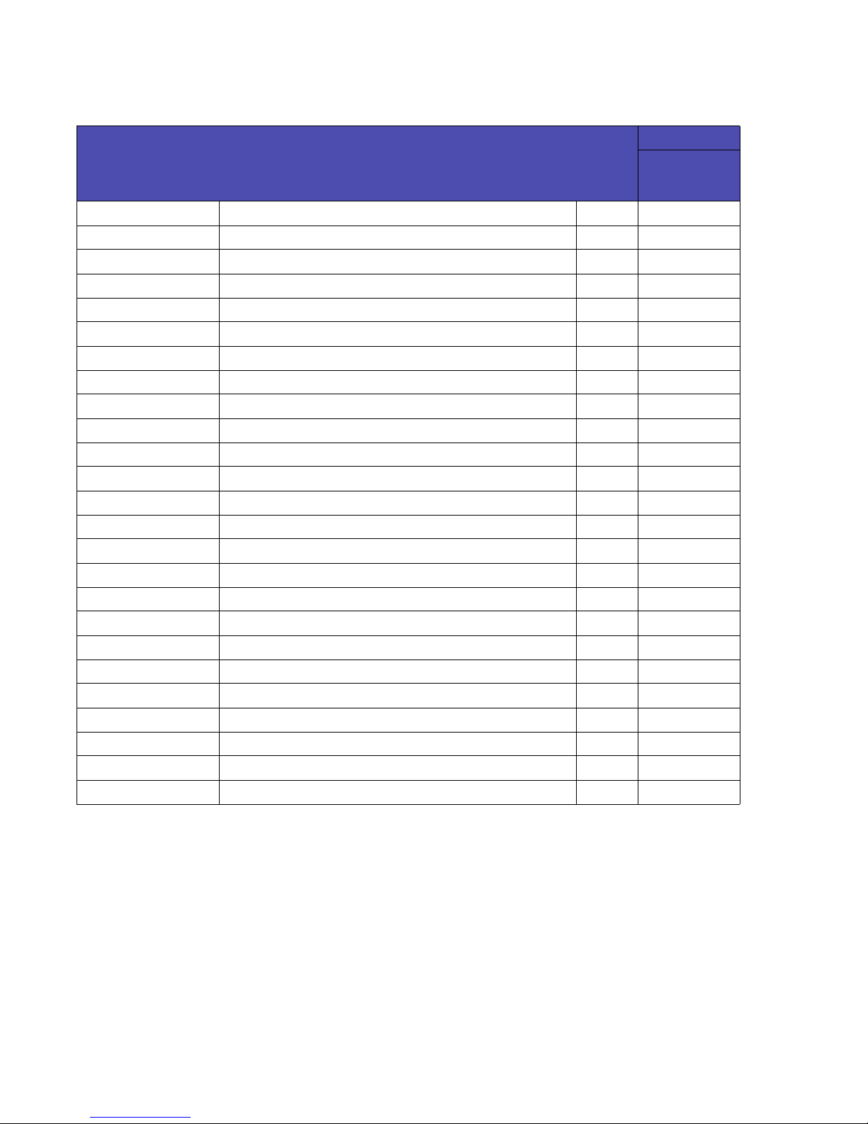
Unit 3: PCL Emulation Support
Table 3-2: GL/2 Commands (continued)
Supported
Not Supported
Command
PU Pen Up 1-27
PW Pen Width 1-29
RA Fill Rectangle Absolute 1-28
RF Define Raster Fill 1-29
RO Rotate Coordinate System 1-27
RR Fill Rectangle Relative 1-28
RT Arc Relative Three Point 1-27
SA Select Alternate Font 1-28
SB Scalable/Bitmapped Fonts 1-28
SC Scale 1-27
SD Define Standard Font 1-28
SI Absolute Character Size 1-28
SL Character Slant 1-28
SM Symbol Mode 1-29
SP Select Pen 1-29
Page numbers reference command descriptions. Printer Model
Function Page D512
SR Relative Character Size 1-28
SS Select Standard Font 1-29
SV Screened Vectors 1-29
SV Screened Vectors - 9, level 1-29
TD Transparent Data 1-29
TM Threshold Matrix 1-29
TR Transparency Mode 1-29
UL User Defined Line 1-29
WG Fill Wedge 1-28
WU Pen Width Units 1-29
Page 3-8 SATO D512 PCL Programming Manual

1PJL SUPPORT
SATO D512 PCL Programming Manual Page 4-1
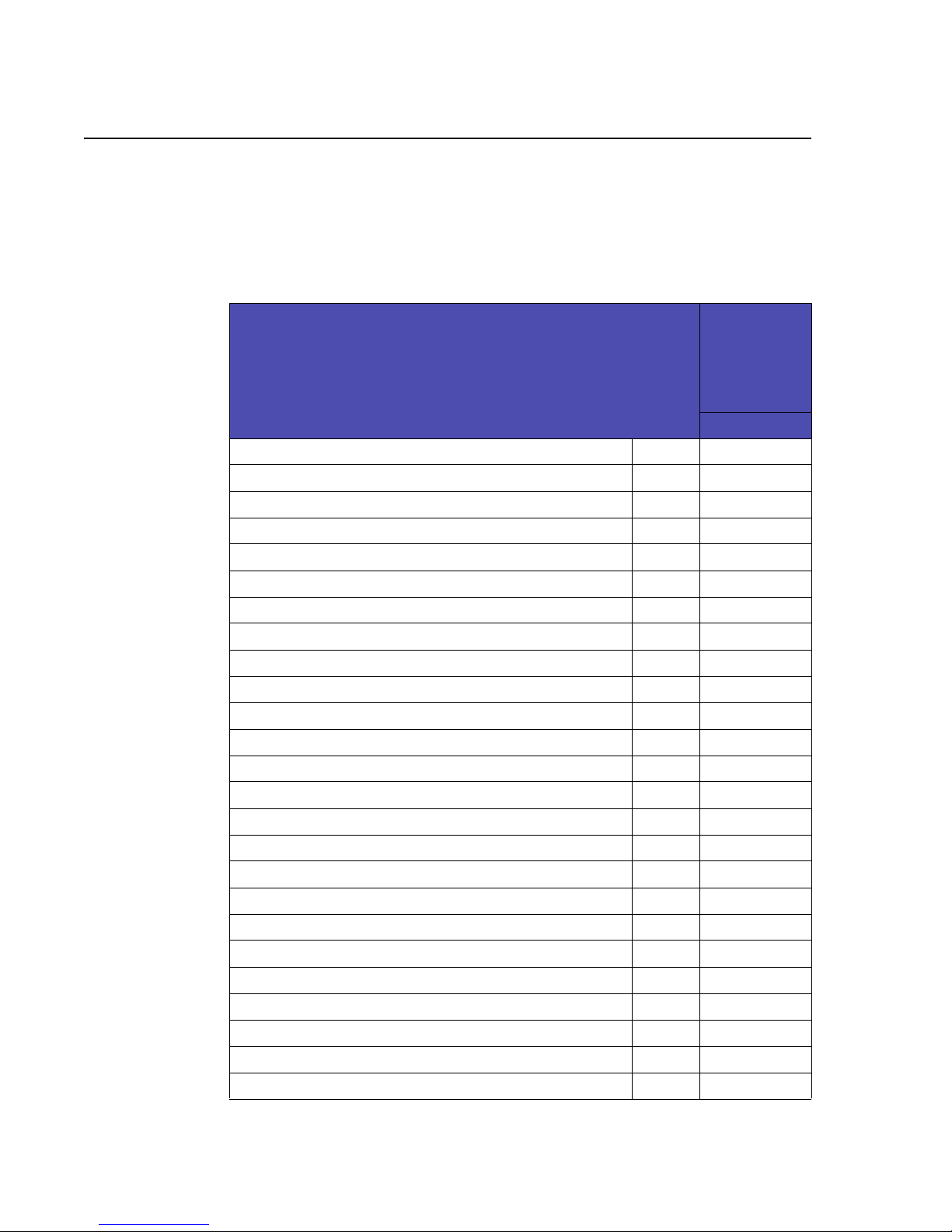
Unit 4: Printer Job Language Support
PRINTER JOB LANGUAGE SUPPORT
The following tables list PJL commands and identify printers that support them.
For detailed information about PJL commands, see Section 2, the Printer Job
Language section, in this manual. All commands may not have a full description.
Table 4-1: PJL Variables
Supported
Not Supported
Page numbers reference variable descriptions and are listed for supported
variables only.
Default values are listed for exceptions only.
Variable Name Page D512
AUTOCONT
AUTOSELECT
BINDING
BITSPERPIXEL
CLEARABLEWARNINGS
Printer Model
CONTEXTSWITCH
COPIES 2-10
CPLOCK
DENSITY
DISKLOCK
DUPLEX
ECONOMODE
FORMATTERNUMBER
FORMLINES 2-10
HOLD
HOLDKEY
HOLDTYPE
IMAGEADAPT
INTRAY1
INTRAY2
INTRAY3
INTRAY4
INTRAY5
INTRAY1SIZE
INTRAY2SIZE
Page 4-2 SATO D512 PCL Programming Manual

Unit 4: Printer Job Language Support
Table 4-1: PJL Variables (continued)
Supported
Not Supported
Page numbers reference variable descriptions and are listed for supported
variables only.
Default values are listed for exceptions only.
Variable Name Page D512
INTRAY3SIZE
INTRAY4SIZE
INTRAY5SIZE
IOBUFFER
IOSIZE
JOBATTR
JOBNAME 2-10
JOBOFFSET
LANG
LOWTONER
Printer Model
MANUALFEED
MEDIASOURCE
MEDIATYPE
MPTRAY
ORIENTATION 2-10
OUTBIN
PAGEPROTECT
PA PE R
PARALLEL
PA SS WO R D
PERSONALITY
POWERSAVE
POWERSAVETIME
PRINTQUALITY
QTY
RENDERMODE
REPRINT
RESOLUTION 2-10
RESOURCESAVE
RESOURCESAVESIZE
RET
TIMEOUT
SATO D512 PCL Programming Manual Page 4-3
Unit 4: Printer Job Language Support
Table 4-1: PJL Variables (continued)
Supported
Not Supported
Page numbers reference variable descriptions and are listed for supported
variables only.
Default values are listed for exceptions only.
Variable Name Page D512
USERNAME
WIDEA4
Table 4-2: Common Variables for PCL Emulation
Supported
Not Supported
Page numbers reference variable descriptions.
Variable Name Page D512
FONTNUMBER
Printer Model
Printer Model
FONTSOURCE
PITCH
PTSIZE
SYMSET
Table 4-3: Common Variables for PostScript Emulation
Supported
Not Supported
Page numbers reference variable descriptions.
Variable Name Page D512
JAMRECOVERY
PRTPSERRS
ADOBEMBT
Printer Model
Page 4-4 SATO D512 PCL Programming Manual
Unit 4: Printer Job Language Support
Table 4-4: Status Readback Commands
Supported
Not Supported
Page numbers reference command descriptions.
Command Name Page D512
Dinquire 2-12
Echo 2-13
Info 2-14
Inquire 2-15
Ustatus 2-16
Ustatusoff 2-17
Table 4-5: USTATUS Unsolicited Status Variables
Printer Model
Supported
Not Supported
Page numbers reference variable descriptions.
Variable Name Page D512
DEVICE 2-16
JOB 2-16
PAGE 2-16
TIMED 2-16
Printer Model
Table 4-6: Device Attendance Messages
Supported
Not Supported
Page numbers reference message descriptions.
Message Page D512
RDYMSG
OPMSG
STMSG
Printer Model
SATO D512 PCL Programming Manual Page 4-5

Unit 4: Printer Job Language Support
Page 4-6 SATO D512 PCL Programming Manual

1BARCODE COMMANDS
SATO D512 PCL Programming Manual Page 5-1

Unit 5: Bar Code Commands
BAR CODE COMMANDS
Table 5-1: PCL Emulation Escape Sequences
Command / Parameters Function / Result
ESC
or
ESC
ESC
or
ESC
ESC
or
ESC
(s#P
)s#P
(s#H
)s#H
(s#V
)s#V
Determines the location of human-readable text printed with the bar
code.
0 Use default value
1 Do not print text
4 Print text under bar code
5 Print text above bar code
Example:
ESC
Select Code 3 of 9 with human-readable text under the barcode. Because
the v and h parameters are not specified, their values default to:
v 0.4 inch
h automatically sized Roman Pillar bold
Selects the font used for human-readable text. The numeric value of # is
of the form CBA, where:
A = typeface 0–5
B = size 0 Automatic font size (default)
C = style 0 Default (bold)
Example:
ESC
Selects Code 3 of 9 with check digit with automatically sized Roman
Pillar Bold Italic text above the bar code. Because the v parameter is not
specified, it value defaults to:
v 0.7 inch
Selects the height of the bar in points (1/72 inch).
Except in symbologies where #V is a fixed value, the bar height can be
varied from a minimum of 3 points (0.04 inch, 1 mm) to a maximum of
960 points (13.33 inch, 33 cm).
Example:
ESC
Selects the Codabar symbology with a bar height of 0.5 inch. Because
the p and h parameters are not specified, their values default to:
p Do not print text
h Not applicable because of #p parameter value
(s4p24670T
Note: The valid range is 0 to 5,
regardless of the selection, the humanreadable is printed with Roman Pillar
Bold.
1 Bold
2 Bold Italic
3 Bold
4 Bold Italic
(5p504h24671T
(s36v24750T
Page 5-2 SATO D512 PCL Programming Manual

Unit 5: Bar Code Commands
Table 5-2: PCL Emulation Parameter List
Command Function / Parameter (#v units are in 1/72”
ESC
(s#T
or
ESC
)s#T
Typ e face # Bar Code Symbology #v #p
24600 UPC-A 74.4 4 N 11 Yes
24601 UPC-A + 2-digit supplemental 74.4 4 N 13 Yes
24602 UPC-A + 5-digit supplemental 74.4 4 N 16 Yes
24610 UPC-E 28.8 4 N 6 Yes
24611 UPC-E + 2-digit supplemental 28.8 4 N 8 Yes
24612 UPC-E + 5-digit supplemental 28.8 4 N 11 Yes
24620 EAN/JAN-8 50.4 4 N 7 Yes
24621 EAN/JAN-8 + 2-digit supplemental 50.4 4 N 9 Yes
24622 EAN/JAN-8 + 5-digit supplemental 50.4 4 N 12 Yes
24630 EAN/JAN-13 74.4 4 N 12 Yes
24631 EAN/JAN-13 + 2-digit supplemental 74.4 4 N 14 Yes
24632 EAN/JAN-13 + 5-digit supplemental 74.4 4 N 17 Yes
24640 Interleaved 2 of 5 28.8 1 N Even No
Select the bar code symbology.
Default Parameters
1
Characters
Encoded
2
Symbol
Length
3
3
3
3
3
3
3
3
3
3
3
3
Checksum
Character
24641 Interleaved 2 of 5 + check digit 28.8 1 N Odd Yes
24650 Industrial 2 of 5 28.8 1 N --- No
24651 Industrial 2 of 5 + check digit 28.8 1 N --- Yes
24660 Matrix 2 of 5 28.8 1 N --- No
24661 Matrix 2 of 5 + check digit 28.8 1 N --- Yes
24670 Code 3 of 9 28.8 1 M --- No
24671 Code 3 of 9 + check digit 28.8 1 M --- Yes
24672 Code 3 of 9 space encoding 28.8 1 M --- No
24673 Code 3 of 9 space encode +check digit 28.8 1 M --- Yes
24680 Code 3 of 9 extended 28.8 1 M --- No
24681 Code 3 of 9 extended + check digit 28.8 1 M --- Yes
24690 Code 93 28.8 1 M --- Yes
24691 Code 93 extended 28.8 1 M --- Yes
24700 Code 128 autoswitch 28.8 1 M --- Yes
1
For bar code symbologies, the default value of the #H text font parameter is CBA =
000 (automatically sized Roman Pillar bold).
2
Does not include checksum character.
3
Checksum character is always printed if human-readable text is specified.
* = Fixed value, cannot be changed
N = Numeric
M = Mixed
SATO D512 PCL Programming Manual Page 5-3

Unit 5: Bar Code Commands
Table 5-2: PCL Emulation Parameter List (continued)
Command Function / Parameter (#v units are in 1/72”
ESC
or
ESC
(s#T
)s#T
Select the bar code symbology.
Default Parameters
1
2
Typ e face # Bar Code Symbology #v #p
Characters
Encoded
Length
Symbol
24701 Code 128 A 28.8 1 M --- Yes
24702 Code 128 B 28.8 1 M --- Yes
24704 Code 128 C 28.8 1 M --- Yes
24710 UCC 128 28.8 5 M ---
24720 EAN 128 28.8 1 M --- Yes
24750 Codabar 28.8 1 M --- No
24751 Codabar +MOD 16 check digit 28.8 1 M --- Yes
24760 MSI 28.8 1 N --- No
24761 MSI + mod10 + mod10 check digits 28.8 1 N --- Yes
24762 MSI + mod10 + mod10 check digits 28.8 1 N --- Yes
24763 MSI + mod11 + mod10 check digits 28.8 1 N --- Yes
24770 POSTNET 5-digit ZIP code 9* 1* N 5 Yes
24771 POSTNET 9-digit ZIP code 9* 1* N 9 Yes
24772 POSTNET 11-digit Delivery Point Code 9* 1* N 11 Yes
24880 MaxiCode --- 1 Y 1’ square Yes
24850 PDF417 --- 1 Y --- Yes
1
For bar code symbologies, the default value of the #H text font parameter is CBA =
000 (automatically sized Roman Pillar bold).
2
Does not include checksum character.
3
Checksum character is always printed if human-readable text is specified.
* = Fixed value, cannot be changed
N = Numeric
M = Mixed
Checksum
Character
CURSOR POSITIONING
Cursor positioning is set as follows when printing with the Sato Bar Code Option:
• From the current cursor position, bar code printing begins at the bottom left corner of the
left bar.
• The cursor is located at the bottom right corner of the right bar when printing is complete.
• This cursor positioning applies both with and without accompanying human-readable text.
Page 5-4 SATO D512 PCL Programming Manual

Unit 5: Bar Code Commands
TWO-DIMENSIONAL BAR CODES
MAXICODE PCL 5 COMMANDS TO SUPPORT MAXICODE BAR CODES
Sato provides two methods to print MaxiCode bar codes. The final method uses two Sato unique
commands
ESC
&x#W and
ESC
&y#W.
B
AR CODE DESCRIPTOR
ESC
&X#W[DESCRIPTOR DATA]
This escape sequence is used to describe not only what bar code to print, but also all of the
parameter settings required to build the bar code. The first two bytes of this command always
designate the symbology. The remaining byte is then interpreted to specify the mode. # is the
number of bytes of descriptor data. The descriptor data for MaxiCode would be the binary string
00 02 01 (for mode 1), 00 02 02 (for mode 2), and so on.
T
RANSFER BAR CODE DATA ESC&Y#W[BAR CODE DATA]
This new PCL 5 command is used to transfer a raw block of bar code data to be encoded. The
bar code data is encoded according to what was specified in the last valid Bar Code Descriptor
command received. If no valid Descriptor is sent, then this command is ignored and the data is
flushed. # is the number of bytes of bar code data.
B
AR CODE DESCRIPTOR FOR MAXICODE
Below is the header definition of the bar code descriptor for MaxiCode:
Table 5-3: MaxiCode Descriptor Header Definition
Bytes MSB LSB
0–1 Symbology ID byte (00x) Symbology ID byte 2 (02x)
2–3 Mode Reserved
Symbology ID bytes 0 and 1: (Required = 00 02x)
These two bytes signify the symbology. For MaxiCode, these two bytes must
be 00x and 02x.
Mode: (Default = 02x)
This field designates what mode to use when interpreting the input data. Valid
modes are (in hex).
Table 5-4: MaxiCode Mode Values
Bytes MSB
02x Structured carrier message with numeric postal code
03x Structured carrier message with alphanumeric postal code
04x Standard symbol with standard error correction
05x Full symbol with enhanced error correction
06x Reader Program with standard error correction
SATO D512 PCL Programming Manual Page 5-5

Unit 5: Bar Code Commands
MaxiCode Notes
Depending on the mode, the input data sent with the Transfer Bar Code Data
command must follow the following rules:
Rule 1: For all modes the input data must start with a label-number field and
number-of-labels field. Both fields are one digit in length and are
terminated with either a comma or Group Separator (GS, ASCII 29,
hexadecimal 1D).
Rule 2: For modes 2 and 3 there are 3 extra fields that must follow the label
fields. These include the postal code, country code, and class of
service. Each field must be terminated with either a comma or GS.
Rule 3: A mode 2 postal code can be 0 to 9 digits.
Rule 4: A mode 3 postal code can be 0 to 6 alphanumeric characters (any
printable character in code set A as defined in AIM spec).
Rule 5: The country code must be 3 digits in length and thus padded with
leading zeros if necessary.
Rule 6: The class of service must be 3 digits in length and thus padded with
leading in zeros if necessary.
Rule 7: For modes 2 and 3 an optional ANSI Message Header (for example
[)>RS01GSyy) can be inserted prior to the postal code. (RS = record
separator, ASCII 30, hexadecimal 1D;yy is a two digit year). This
message is automatically moved to the secondary message. Neither
a group separator nor a comma should terminate this message.
An optional secondary message follow the class of service for modes 2
and 3. For modes 4, 5, and 6 the message follows the number-of-labels field.
Page 5-6 SATO D512 PCL Programming Manual

Unit 5: Bar Code Commands
MAXICODE EXAMPLES USING TRANSFER BAR CODE DATA COMMAND
Here are some MaxiCode examples of the ASCII data that would be sent with the Transfer Bar
Code Data Command:
Mode 2, separated with commas:
ESC
&y48W1,1,40361,840,001,This is the secondary message.
Mode 3, separated with commas:
ESC
&y48W1,1,ABC01,840,001,This is the secondary message.
Mode 3, separated with GS and commas plus optional ANSI Message
Header (yy=99):
ESC
&y45W1,1,[)RS01GS99ABC01GS840GS022GSsecondary message
Mode 4, separated with commas:
ESC
&y28W1,1, Here is a mode 4 message
H
UMAN-READABLE TEXT
Because two-dimensional bar codes are capable of encoding thousands of characters, humanreadable interpretation of the data may not be practical. Alternatively, descriptive text rather than
literal text may be printed with the symbol. If printed, any character size and font available may
be selected, and the text may be printed anywhere desired near the symbol. The text must not
interfere with the bar code symbol or the quiet zones.
F
UNCTIONAL PARAMETERS FOR MAXICODE (TYPEFACE SELECTION METHOD)
The data sent when using this second technique of printing MaxiCode symbols will follow the
same rules that exist for data sent using the Transfer Bar Code Data Command to print
MaxiCode symbols, with the following change to rule 1. (See “Rule 1” on page 2-6.) The input
data must start with a label-number field, a number-of-labels field, and a mode field. All three of
these fields are one digit in length and are terminated with either a comma or Group Separator
(GS, ASCII 29).
Example of MaxiCode commands using typeface selection:
ESC
(s24800T
ESC
&p105X1,1,3,152382802,840,001,[)
RS01GS961Z00004951GSUPSNGS06X610GS159GS1234567GS
1/1GS10GSYGS634 ALPHA
DRGSGSPITTBURGHGSPARS
Where:
ESC
=escape character decimal 27, hexadecimal 1B
RS=record separator decimal 30, hexadecimal 1E
GS=group separator decimal 29, hexadecimal 1D
SATO D512 PCL Programming Manual Page 5-7

Unit 5: Bar Code Commands
FUNCTIONAL PARAMETERS FOR PDF417
The #p parameter specifies the level of error correction to use: 0–8. In relation to the fields of the
Sato Bar Code Descriptor for PDF417, the following correspondences exist when using this
technique:
ECC Level Specified by #p parameter
Examples of PDF 417 commands:
ESC
(s0p24850TABCDEFG
Encodes the string “ABCDEFG” in a PDF417 symbol with error correction
level 0.
Page 5-8 SATO D512 PCL Programming Manual

1PRINTER LANGUAGE
CHANGE COMMANDS
• Setting the printer to SBPL
• Setting the printer to PCL
SATO D512 PCL Programming Manual Page 6-1
Unit 6: PRINTER LANGUAGE CHANGE COMMANDS
ESC+RN
ESC+RNESC+R
ESC+R
PCL Language Set Command
SETTING THE PRINTER TO SBPL LANGUAGE
This chapter discusses setting the printer to the SBPL language, and setting the printer to PCL
language.
Command to set SBPL Language
The SBPL command sets the printer to SBPL mode and causes all
subsequent data to be processed as SBPL data. The change is retained
even if the printer is turned off.
Syntax:
@PJL ENTER LANGUAGE=SBPL<CR><LF>
Response:
None
SETTING THE PRINTER TO PCL LANGUAGE
Command to set PCL Language
The PCL command sets the printer to PCL mode. The change is retained
even if the printer is turned off.
Command Function:
To set the printer language to PCL.
Command Structure:
<ESC>A
Page 6-2 SATO D512 PCL Programming Manual

Unit 6: PRINTER LANGUAGE CHANGE COMMANDS
<ESC>RN
<ESC>Z
SATO D512 PCL Programming Manual Page 6-3

Unit 6: PRINTER LANGUAGE CHANGE COMMANDS
This page intentionally left blank.
Page 6-4 SATO D512 PCL Programming Manual

1SATO CONTACTS
2
3
4

SATO GROUP OF COMPANIES
International Headquarters
SATO INTERNATIONAL PTE. LTD.
438A Alexandra Road #05-01/04,
Alexandra Technopark, Singapore 119967
Phone: 65-6271-2122 Fax: 65-6271-2151
Email: sales@sato-int.com
Website: www.satoworldwide.com
Asia Pacific & Oceania Region
SATO INTERNATIONAL ASIA PACIFIC PTE. LTD.
(Regional Headquarters)
438A Alexandra Road #05-01/04,
Alexandra Technopark, Singapore 119967
Phone: 65-6271-5300 Fax: 65-6273-6011
Email: sales@sato-int.com
Website: www.satoworldwide.com
SATO ASIA PACIFIC PTE. LTD.
438A Alexandra Road #05-01/04,
Alexandra Technopark, Singapore 119967
Phone: 65-6271-5300 Fax: 65-6273-6011
Email: sales@satoasiapacific.com
Website: www.satoworldwide.com, www.satoasiapacific.com
SATO SHANGHAI CO., LTD.
307 Haining Road, ACE Bldg., 10th Floor, Hongkou Area,
Shanghai 200080, China
Phone: 86-21-6306-8899 Fax: 86-21-6309-1318
Email: sales@satochina.com
Website: www.satochina.com
SATO AUTO-ID MALAYSIA SDN. BHD.
No.25, Jalan Pemberita U1/49, Temasya Industrial Park,
Section U1, 40150 Shah Alam, Selangor Darul Ehsan,
Malaysia
Phone: 60-3-7620-8901 Fax: 60-3-5569-4977
Email: sales@satosms.com.my
SATO AUTO-ID (THAILAND) CO., LTD.
292/1 Moo 1 Theparak Road, Tumbol Theparak,
Amphur Muang, Samutprakarn 10270, Thailand
Phone: 662-736-4460 Fax: 662-736-4461
SATO AUSTRALIA PTY LTD.
1/1 Nursery Avenue, Clayton Business Park, Clayton,
VIC 3168, Melbourne, Australia
Phone: 61-3-8814-5330 Fax: 61-3-8814-5335
SATO NEW ZEALAND LTD.
30 Apollo Drive, Mairangi Bay, Auckland , New Zealand
Phone: 64-9-477-2222 Fax: 64-9-477-2228
American Region
SATO INTERNATIONAL AMERICA, INC.
(Regional Headquarters)
10350-A Nations Ford Road, Charlotte, NC 28273, U.S.A.
Phone: 1-704-644-1650 Fax: 1-704-644-1662
Email: satosales@satoamerica.com
Website: www.satoworldwide.com, www.satoamerica.com
SATO AMERICA, INC.
10350-A Nations Ford Road, Charlotte, NC 28273, U.S.A.
Phone: 1-704-644-1650 Fax: 1-704-644-1662
Email: satosales@satoamerica.com
Website: www.satoworldwide.com, www.satoamerica.com
SATO LABELING SOLUTIONS AMERICA, INC.
Romeoville Division
1140 Windham Parkway, Romeoville, IL 60446, U.S.A.
Phone: 1-630-771-4200 Fax: 1-630-771-4210
Email: sales@satolabeling.com
Horticulture Division
930 Jimmy Ann Drive, Daytona Beach, FL 32117, U.S.A.
Phone: 1-386-274-5566 Fax: 1-386-274-5599
Email: sales@satolabeling.com
European Region
SATO INTERNATIONAL EUROPE N.V.
(Regional Headquarters)
Leuvensesteenweg 369, 1932 Sint-Stevens-Woluwe, Belgium
Phone: 32-2-788-80-00 Fax: 32-2-788-80-80
Email: info@be.satoeurope.com
Website: www.satoworldwide.com, www.satoeurope.com
SATO UK LTD.
Valley Road, Harwich, Essex CO12 4RR, United Kingdom
Phone: 49-6272-9201-0 Fax: 49-6272-9201-399
Email: enquiries@satouk.com
Website: www.satoworldwide.com, www.satouk.com
SATO LABELLING SOLUTIONS EUROPE GmbH
Ersheimer Straße 71, 69434 Hirschhorn, Germany
Phone: 44-1255-240000 Fax: 44-1255-240111
SATO FRANCE S.A.S.
Parc d'Activités, Rue Jacques Messager,
59 175 Templemars, France
Phone: 33-3-20-62-96-4 Fax: 33-3-20-62-96-55
SATO POLSKA SP. Z O.O.
ul. Wrocawska 123, Radwanice, 55-015 w. Katarzyna,
Poland
Phone: 48-71-381-03-60 Fax: 48-71-381-03-68
SATO IBERIA S.A.
Dels Corrals Nous, 35-39, Pol. Can Roqueta,
08202 Sabadell, Barcelona, Spain
Phone: 34-902-333-341 Fax: 34-902-333-349
• Extensive contact information of worldwide SATO
operations can be found on the Internet at
www.satoworldwide.com
6
 Loading...