

Version: 1.0
Date: Sept. 19, 2019
AS-9400
Barcode Scanner
User Guide
http://www.argox.com
service@argox.com

AS-9400
i
Note: All brands and trademarks are the property of their respective owners.
Note: The specifications contained herein are subject to change without notice.
User Guide
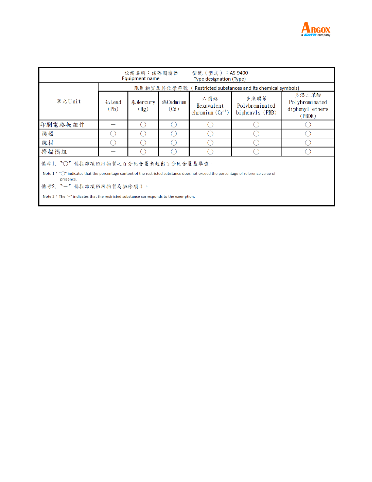
Regulatory Compliance
FEDERAL COMMUNICATIONS COMMISSION INTERFERENCE STATEMENT
This equipment has been tested and found to comply with the limits for a Class B digital device,
pursuant to part 15 of the FCC Rules. These limits are designed to provide reasonable protection
against harmful interference in a residential installation. This equipment generates, uses, and
can radiate radio frequency energy and, if not installed and used in accordance with the
instructions, may cause harmful interference to radio communications. However, there is no
guarantee that interference will not occur in a particular installation. If this equipment does cause
harmful interference to radio or television reception, which can be determined by turning the
equipment off and on, the user is encouraged to try to correct the interference by one or more of
the following measures:
Reorient or relocate the receiving antenna.
Increase the separation between the equipment and receiver.
Connect the equipment into an outlet on a circuit different from that to which the receiver is
connected.
Consult the dealer or an experienced radio/ TV technician for help.
CAUTION:
Any changes or modifications not expressly approved by the grantee of this device could void the
user's authority to operate the equipment.
AS-9400
ii
User Guide
警告使用者:
這是甲類的資訊產品,在居住的環境中使用時,可能會造成射頻干擾,在這種情況下,使用者會被
要求採取某些適當的對策。

AS-9400
iii
User Guide
DEFAULT SETTING ..................................................................................................................................................... 1
DURATION IN SCANNING .................................................................................................................................................. 2
POWER MODE ................................................................................................................................................................ 3
TRIGGER MODE .............................................................................................................................................................. 3
INTERVAL TIME................................................................................................................................................................. 5
BEEPER VOLUME ........................................................................................................................................................... 5
BEEP AFTER GOOD DECODE ......................................................................................................................................... 6
TERMINATOR .................................................................................................................................................................... 6
Contents
Factory Default Configuration ............................................................................................................................. 1
Default Configuration1 ......................................................................................................................................... 1
Default Configuration2 ......................................................................................................................................... 1
Default Configuration3 ......................................................................................................................................... 2
Default Configuration4 ......................................................................................................................................... 2
Default Configuration5 ......................................................................................................................................... 2
INDICATOR LIGHT FUNCTION ........................................................................................................................................... 7
LED AFTER GOOD DECODE ........................................................................................................................................... 7
MUTE ................................................................................................................................................................................ 8
BOOT PROMPT ................................................................................................................................................................. 8
SETUP CODE PROMPT..................................................................................................................................................... 8
TRANSMIT “NO READ” MESSAGE .................................................................................................................................... 9
PARAMETER SCANNING ................................................................................................................................................. 9
SEND SETTING CODE .................................................................................................................................................... 10
LINEAR CODE TYPE SECURITY LEVEL .......................................................................................................................... 10
Linear Security Level 1 .................................................................................................................................... 11
Linear Security Level 2 .................................................................................................................................... 11
Linear Security Level 3 .................................................................................................................................... 12
Linear Security Level 4 ...................................................................................................................................... 12
INVOICE FUNCTION ........................................................................................................................................................ 12
Automatic Filling of Value-added Tax Invoice ................................................................................................ 12
Invoice Type ........................................................................................................................................................ 13
TRANSMIT CODE ID CHARACTER ................................................................................................................................ 13
PREFIX/SUFFIX VALUES ............................................................................................................................................... 14
SCAN DATA TRANSMISSION FORMAT .......................................................................................................................... 16
SERIAL PARAMETERS ................................................................................................................................................... 17
Baud Rate ............................................................................................................................................................ 17
Parity ................................................................................................................................................................... 19
Software Handshaking ..................................................................................................................................... 20

AS-9400
iv
User Guide
COMMUNICATION MODE ................................................................................................................................................ 22
WIEGAND ....................................................................................................................................................................... 24
PS2 MODE ................................................................................................................................................................... 26
FLOODLIGHT CONTROL ................................................................................................................................................. 26
POSITIONING LIGHTS CONTROL (ONLY FOR 2D) ........................................................................................................... 27
SENSITIVITY LEVEL ........................................................................................................................................................ 27
CUSTOM SENSITIVITY .................................................................................................................................................... 28
STABILITY OF INDUCTION TIME ...................................................................................................................................... 28
OUTPUT INTERVAL OF THE SAME CODE ....................................................................................................................... 29
Decode Data Packet Format ........................................................................................................................... 20
Host Serial Response Time-out ...................................................................................................................... 21
Stop Bit Select ................................................................................................................................................. 21
Intercharacter Delay ........................................................................................................................................... 22
Host Character Time-out ................................................................................................................................. 22
Wiegand protocol type ....................................................................................................................................... 24
Wiegand 26 Protocol Output Mode .................................................................................................................. 25
1D IDENTIFIES TWO BARCODES ................................................................................................................................... 29
OUTPUT PRODUCT INFORMATION ................................................................................................................................. 30
OUTPUT CHARACTER SET TYPE ................................................................................................................................... 30
INPUT CHARACTER SET TYPE ................................................................................................................................ ....... 31
USB TYPE .................................................................................................................................................................. 32
KEYBOARD .................................................................................................................................................................. 32
Country/Language Keyboard ............................................................................................................................ 32
Time interval that keyboard outputs character ............................................................................................... 35
Quick Settings of Keyboard Output Time Interval .......................................................................................... 35
Letter case conversion ....................................................................................................................................... 36
Output Ctrl Combination Key ............................................................................................................................ 37
Keyboard Type .................................................................................................................................................... 37
EVENT REPORT ............................................................................................................................................................. 38
Boot Event ........................................................................................................................................................... 38
Trigger Event ....................................................................................................................................................... 38
SETTING CODE PASSWORD MODE ............................................................................................................................... 39
Enable Setting Code Password Mode ............................................................................................................. 39
Input Setting Code Password ........................................................................................................................... 39
Modify Setting Code Password ......................................................................................................................... 40
Logout Password .............................................................................................................................................. 40
DISABLE PASSIVE TRIGGER SCANNING .......................................................................................................................... 40
BARCODE GLOBAL SWITCH ........................................................................................................................................... 41
1D Global Switch .............................................................................................................................................. 41

AS-9400
v
User Guide
UPC/EAN ...................................................................................................................................................................... 42
2D Global Switch ................................................................................................................................................ 41
All Barcode Switch .............................................................................................................................................. 41
Enable/Disable UPC-A ....................................................................................................................................... 42
Enable/Disable UPC-E ..................................................................................................................................... 42
Enable/Disable EAN-8 ....................................................................................................................................... 43
Enable/Disable EAN-13 ................................................................................................................................... 43
Enable/Disable Bookland EAN(ISBN) ........................................................................................................... 44
Decode UPC/EAN Supplementals ................................................................................................................. 44
Transmit UPC-A Check Digit............................................................................................................................. 45
Transmit UPC-E Check Digit............................................................................................................................. 45
UPC-A Preamble ............................................................................................................................................ 46
UPC-E Preamble .............................................................................................................................................. 47
Convert UPC-E to UPC-A ................................................................................................................................ 48
EAN-8 Zero Extend ........................................................................................................................................ 48
Bookland ISBN Format .................................................................................................................................... 49
UPC/EAN Security Level ................................................................................................................................... 49
CODE 128 ...................................................................................................................................................................... 51
Enable/Disable Code 128 ................................................................................................................................ 51
Enable/Disable GS1-128 (formerly UCC/EAN-128) ...................................................................................... 51
Enable/Disable ISBT 128 ................................................................................................................................ 52
Lengths for Code 128 ....................................................................................................................................... 52
CODE 39 ........................................................................................................................................................................ 52
Enable/Disable Code 39 .................................................................................................................................... 52
Set Lengths for Code 39 ................................................................................................................................ 53
Code 39 Check Digit Verification .................................................................................................................... 54
Transmit Code 39 Check Digit ........................................................................................................................ 54
Enable/Disable Code 39 Full ASCII ................................................................................................ ............... 55
Code 39 Transport Start Character and Terminator ................................................................................ 55
Convert Code 39 to Code 32 (Italian Pharma Code) .................................................................................. 56
Code 32 Prefix ................................................................................................................................................. 56
CODE 93 ........................................................................................................................................................................ 57
Enable/Disable Code 93 .................................................................................................................................... 57
Set Lengths for Code 93 .................................................................................................................................... 57
CODE 11 ........................................................................................................................................................................ 58
Enable/Disable Code 11 .................................................................................................................................... 58
Set Lengths for Code 11 .................................................................................................................................. 58
Code 11 Check Digit Verification .................................................................................................................... 60
Transmit Code 11 Check Digits ...................................................................................................................... 60

AS-9400
vi
User Guide
INTERLEAVED 2 OF 5/ITF/ ............................................................................................................................................. 61
DISCRETE 2 OF 5/INDUSTRIAL 2 OF 5/IND25 ............................................................................................................... 64
MATRIX 25 ..................................................................................................................................................................... 65
STANDARD 25/IATA 25 ................................................................................................................................................. 67
Enable/Disable Interleaved 2 of 5 .................................................................................................................... 61
Set Lengths for Interleaved 2 of 5 Interleaved ............................................................................................. 61
I 2 of 5 Check Digit Verification ....................................................................................................................... 62
Transmit I 2 of 5 Check Digit ........................................................................................................................... 63
Convert I 2 of 5 to EAN-13 .............................................................................................................................. 63
Enable/Disable Discrete 2 of 5 ......................................................................................................................... 64
Set Lengths for Discrete 2 of 5 Discrete ........................................................................................................ 64
Enable/Disable Matrix 25 ................................................................................................ ................................... 65
Matrix 25 Check Digit Verification .................................................................................................................. 66
Transmit Matrix 25 Check Character ............................................................................................................... 66
Set Lengths for Matrix 25 ............................................................................................................................... 66
Enable/Disable Standard 25 ............................................................................................................................. 67
Standard 25 Check Digit Verification ............................................................................................................. 68
Transmit Check Character ................................................................................................................................ 68
Set Lengths for Standard 25 ........................................................................................................................... 68
CODABAR ....................................................................................................................................................................... 69
Enable/Disable Codabar .................................................................................................................................... 69
Set Lengths for Codabar .................................................................................................................................. 70
NOTIS Editing ................................................................................................................................................... 71
Start Character and Terminator ........................................................................................................................ 71
Letter Case Setting of Start Character and Teminator ................................................................................ 72
MSI/MSI PLESSEY ................................ ................................ ................................................................ ..................... 72
Enable/Disable MSI .......................................................................................................................................... 72
Set Lengths for MSI .......................................................................................................................................... 73
MSI Check Digits .............................................................................................................................................. 74
Transmit MSI Check Digit ................................................................................................................................ 74
MSI Check Digit Algorithm ............................................................................................................................... 75
GS1 DATABAR/RSS ..................................................................................................................................................... 75
Enable/Disable GS1 DataBar-14 .................................................................................................................... 75
Enable/Disable GS1 DataBar Limited.............................................................................................................. 76
Enable/Disable GS1 DataBar Expanded ........................................................................................................ 76
PDF417 ......................................................................................................................................................................... 77
Enable/Disable PDF417 .................................................................................................................................... 77
Read Multi-code .................................................................................................................................................. 77
Read Normal Phase/ Phase Reversal ........................................................................................................... 78

AS-9400
vii
User Guide
QR ................................................................................................................................................................................. 78
DATA MATRIX(DM) ........................................................................................................................................................ 80
MAXI CODE .................................................................................................................................................................... 82
AZTEC CODE .................................................................................................................................................................. 82
HAN XIN CODE ............................................................................................................................................................... 83
Enable/Disable QR ........................................................................................................................................... 78
Read Multi-code .................................................................................................................................................. 79
ECI Control ...................................................................................................................................................... 79
Enable/Disable Data Matrix(DM) ...................................................................................................................... 80
Read Multi-code .................................................................................................................................................. 80
Read Normal Phase/ Phase Reversal ............................................................................................................. 81
ECI Control ...................................................................................................................................................... 81
Enable/Disable Maxi Code ................................................................................................................................ 82
Enable/Disable Aztec Code .............................................................................................................................. 82
Enable/Disable Han Xin Code .......................................................................................................................... 83
Read Multi-code .................................................................................................................................................. 83
Read Normal Phase/ Phase Reversal ............................................................................................................. 84
ISSN .............................................................................................................................................................................. 84
PLESSEY ..................................................................................................................................................................... 85
1. APPENDIX .................................................................................................................................................................. 86
NUMERIC BAR CODES ................................................................................................................................................... 86
CANCEL ........................................................................................................................................................................ 87
SETTING CODE LENGTHS VIA SERIAL COMMANDS ...................................................................................................... 87
SETTING PREFIXES AND SUFFIXES VIA SERIAL COMMANDS ........................................................................................ 88
AIM CODE IDENTIFIERS AIM ......................................................................................................................................... 95
PARAMETER COMMAND ............................................................................................................................................... 96

AS-9400
1
User Guide
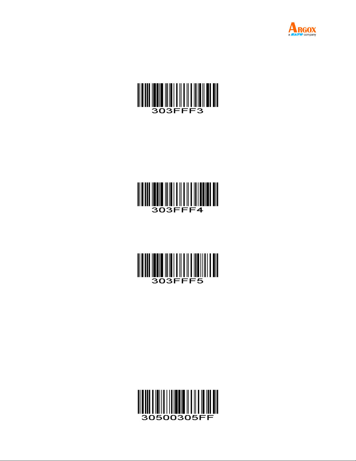
Default Setting
To restore Factory Default Configuration or Default Configuration 1-5, scan the appropriate bar code
below.
Set Factory Defaults - Scan this bar code to restore the factory default values listed in Table 4-6.
Factory Default Configuration
(0x00)
Note:Default configurations of the scan engine depend on factory default configuration.
Default Configuration1
The parameter is main for the POS,.
Communication Mode: Serial port
Trigger Mode: Key holding.
Terminator:Disable
(0x01)
Default Configuration2
The parameter is main for Self-help parameter configuration,
Communication Mode: USB KBW
Trigger Mode: Auto-induction
Terminator: Auto newline(\r\n)
(0x02)
AS-9400
2
User Guide
Default Configuration3
The parameter is main for scan engine parameters configuration
Communication Mode: USB KBW
Trigger Mode: Key holding
Terminator : Enter(\r)
Default Configuration4
Communication Mode: Serial port 9600
Trigger Mode: Key holding.
Terminator: Auto newline
2D barcode only open QR and DM.
Default Configuration5
Not yet enabled
(0x03)
(0x04)
(0x05)
Duration in Scanning
Parameter # 0x88
This parameter sets the maximum time decode processing continues during a scan attempt. It is
programmable in 0.1 second increments from 0.50 to 25.5 seconds.
To set a duration in scanning, scan the bar code below. Next scan threeNumeric Bar Codes in
appendixthat correspond to the desired on time. Single digit numbers must have a leading zero. For example,
to set an on time of 0.5 seconds, scan the bar code below, then scan the "0", "0" and "5" bar codes; to set an
on time of 10.5 seconds, scan the bar code below, then scan the "1", "0" and "5" bar codes. To change the
selection or cancel an incorrect entry, scan Cancel in appendix.
Duration in Scanning(Default: 3.0 sec.)

AS-9400
3
User Guide
Power Mode
Parameter # 0x80
This parameter determines the power mode of the engine.
In Low Power mode, the scan engine enters into a low power consumption Sleep power state
whenever possible (provided all WAKEUP commands were released). SeePower Management .
In Continuous Power mode, the scan engine remains in the Awake state after each decode attempt (see
Power Management).
The Sleep and Awake commands (see SLEEP and WAKEUP) can be used to change the power state in
either the Low Power mode or the Continuous Power mode.
Continuous Power
(0x00)
Low Power
(0x01)
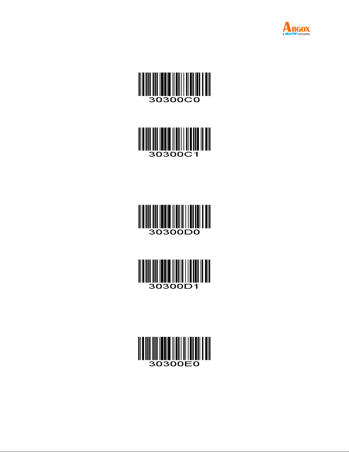
Trigger Mode
Parameter # 0x8A
(Level)Key Holding
Press the button to trigger the reading, release the button to end the reading. Reading success or reading
time over a single reading time will end the reading.
(Pulse)Single Key Trigger
Detects the change of the key level (Maintain 30ms, depending on the product )to start reading, and then
detects the change of the key level (Maintain 30ms, depending on the product )again to end reading. Reading
success or reading time over a single reading time will end the reading.
ContinuousMode
The reading engine performs continuous work. Reading success or reading time over a single reading
time will end the reading. More than the specified time will automatically trigger the next reading.
Automatic Induction Mode
In automatic induction mode,the scan engine detects the brightness of the surroundings. Trigger reading
when the brightness changes. Reading success or reading time over a single reading time will end the reading.
Regardless of the last success or failure to read, re-enter the detection of the surrounding environment
brightness.
Host
Through the command to trigger the scan engine to read, also through the command to trigger the scan
engine to end reading. Reading success or reading time over a single reading time will end the reading.
Note: Key Trigger(Level and Pulse) still valid in other modes

AS-9400
4
User Guide
*
% &
Level
(0X00)
Pulse
(0X02)
Continuous
(0X04)
#
Automatic Induction Mode
(0x09)
Host
(0X08)
(0x0A)
Button Continuous

AS-9400
5
User Guide
Interval Time
Parameter # 0x89
The interval time between two readings in continuous mode. Regardless of the last success or failure to
read, more than the specified time will automatically trigger the next reading.
Default: 500ms,unit: 100ms,range: 0-9900ms
To set a Interval Time, scan the bar code below. Next scan twoNumeric Bar Codes in appendixthat
correspond to the desired time-out. Single digit values must have a leading zero.For example, to set a time-out
of 0.5 seconds, scan the bar code below, then scan the “0” and “5” bar codes. To change the selection or
cancel an incorrect entry, scan Cancel in appendix..
Interval Time
(Default: 500ms.)
Beeper Volume
Parameter # 0x8C
To select a decode beep volume, scan the appropriate bar code.
Low
(0x02)
Medium
(0x01)
*High
(0x00)

AS-9400
6
User Guide
Beep After Good Decode
Parameter # 0x38
Scan this symbol to set the scan engine to beep after a good decode.
*Beep After Good Decode
(0x01)
Scan this symbol to set the scan engine not to beep after a good decode. The beeper still operates
during parameter menu scanning and indicates error conditions.
Do Not Beep After Good Decode
(0x00)
Terminator
Parameter # 0xF20x05
Add character format: Decode Data+Terminator.
* Disable
(0x00)
#
CR LF
(0x01)
%
CR
(0x02)
TAB
(0x03)

AS-9400
7
User Guide
CR CR
(0x04)
CR LF CR LF
(0x05)
Indicator Light Function
Parameter # 0xF2 0x0A
Scan the appropriate bar code below to set indicator light function.
Good Decode
(0x00)
Power LED
(0x01)
LED After Good Decode
Parameter # 0xF2 0x0B
To enable or disable LED after good decode, scan the appropriate bar code below.
Disable
(0x00)
Enable
(0x01)
AS-9400
8
User Guide
Mute
Parameter # 0xF2 0x0C
To enable or disable close all prompt, scan the appropriate bar code below.
Boot prompt
Parameter # 0xF2 0x0D
* Disable
(0x00)
Enable
(0x01)
Disable
(0x00)
* Enable
(0x01)
Setup Code Prompt
Parameter # 0xF2 0x0E
Disable
(0x00)

AS-9400
9
User Guide
* Enable
(0x01)
Transmit “No Read” Message
Parameter # 0x5E
Enable this option to transmit “NR” if a symbol does not decode during the timeout period or before the
trigger is released. Any enabled prefix or suffixes are appended around this message.
Enable No Read
(0x01)
When disabled, and a symbol cannot be decoded, no message is sent to the host.
*Disable No Read
(0x00)
Parameter Scanning
Parameter # 0xEC
To disable decoding of parameter bar codes, scan the bar code below. The Set Defaults parameter bar
code can still be decoded. To enable decoding of parameter bar codes, either scan Enable Parameter
Scanning below, Set Factory Defaults or set this parameter to 0x01 via a serial command.
*Enable Parameter Scanning
(0x01)
Disable Parameter Scanning
(0x00)

AS-9400
10
User Guide
Send Setting Code
Parameter # 0xF1 0x71
Enable Send Setting Code to transmit bar codes in the following format, in Code 128, to the host:
<FNC3>L<any length data>
<FNC3>B<12 characters of data>
Note that the special Code 128 character <FNC3> must appear at the beginning of this data. However, if
the appropriate data does not follow this as shown above, it does not transmit to the host device.
<FNC3>L<any length data>
<FNC3>B<12 characters of data>
Enable Send Setting Code
(0x01)
*Disable Send Setting Code
(0x00)
Linear Code Type Security Level
Parameter # 0x4E
The scan engine offers four levels of decode security for linear code types (e.g. Code 39, Interleaved 2 of
5). Select higher security levels for decreasing levels of bar code quality. As security levels increase, the scan
engine’s aggressiveness decreases.
Select the security level appropriate for your bar code quality.
AS-9400
11
Code Type
Length
Codabar
All
MSI
4 or less
D 2 of 5
8 or less
I 2 of 5
8 or less
User Guide
Linear Security Level 1
The following code types must be successfully read twice before being decoded:
*Linear Security Level 1
(0x01)
Table 3-1
Linear Security Level 2
All code types must be successfully read twice before being decoded.
Linear Security Level 2
(0x02)
AS-9400
12
Code Type
Length
MSI
4 or less
D 2 of 5
8 or less
I 2 of 5
8 or less
User Guide
Linear Security Level 3
Code types other than the following must be successfully read twice before being decoded. The
following codes must be read three times:
Linear Security Level 3
(0x03)
Table 3-2
Linear Security Level 4
All code types must be successfully read three times before being decoded.
Linear Security Level 4
(0x04)
Invoice Function
Open the invoice function, automatically shut down CODE128 code, if you need to read CODE128, can
open CODE128.
Automatic Filling of Value-added Tax Invoice
Parameter # 0xF2 0x08
Disable *
(0x00)

AS-9400
13
User Guide
Invoice Type
Parameter # 0xF2 0xAA
Enable
(0x01)
*Special Invoice
(0x00)
Plain Invoice
(0x01)
Transmit Code ID Character
Parameter # 0x2D
A code ID character identifies the code type of a scanned bar code. This can be useful when decoding
more than one code type. The code ID character is inserted between the prefix character (if selected) and the
decoded symbol.
Select no code ID character, a Symbol Code ID character, or an AIM Code ID character. The Symbol
Code ID characters are listed below; see AIM Code Identifiers.
A = UPC-A, UPC-E, EAN-8, EAN-13
B = Code 39, Code 32
C = Codabar
D = Code 128, ISBT 128, AIM128
E = Code 93
F = Interleaved 2 of 5/ITF, ITF14
G = Industrial 2 of 5, Standard 2 of 5
H = Code11
J = MSI, MSI/Plessey
K = UCC/EAN-128/GS1-128
L = Bookland EAN/ISBN, ISSN
M = Trioptic Code 39
N = Coupon Code
R = GS1 DataBar-14, GS1 DataBar Limited, GS1 DataBar Expanded, RSS
S = SETUP128
w = Deutsche14
l = Deutsche12
o = NEC25/COOP25

AS-9400
14
User Guide
V = Matrix 25
r = PDF417
u = DataMatrix(DM)
q = QR
a = Aztec Code
x = Maxi Code
v = Veri Code
c = HanXin
Prefix/Suffix Values
SymbolCode ID Character Code ID
(0x02)
AimCode ID Character AIM ID
(0x01)
*None
(0x00)
Parameter # P = 0x69, S1 = 0x68, S2 = 0x6A
A prefix and/or one or two suffixes can be appended to scan data for use in data editing. To set these
values, scan a four-digit number (i.e. four bar codes) that corresponds to ASCII values. See the Table 4-3 and
Numeric Bar Codes in appendix. To change the selection or cancel an incorrect entry, scan Cancel in
appendix.To set the Prefix/Suffix values via serial commands, see Setting Prefixes and Suffixes Via Serial
Commands.
NOTE In order to use Prefix/Suffix values, the Scan Data Transmission Format must be set.
Scan Prefix

AS-9400
15
User Guide
Scan Suffix 1
Scan Suffix 2
Data Format Cancel
AS-9400
16
User Guide
Scan Data Transmission Format
Parameter # 0xEB
To change the Scan Data Transmission Format, scan one of the eight bar codes corresponding to the
desired format.
*Data As Is
(0x00)
<DATA><SUFFIX 1>
(0x01)
<DATA><SUFFIX2>
(0x02)
<DATA><SUFFIX 1><SUFFIX 2>
(0x03)
<PREFIX><DATA >
(0x04)
<PREFIX><DATA><SUFFIX 1>
(0x05)

AS-9400
17
User Guide
<PREFIX><DATA><SUFFIX 2>
(0x06)
<PREFIX><DATA><SUFFIX 1><SUFFIX 2>
(0x07)
Serial Parameters
Baud Rate
Parameter # 0x9C
Baud rate is the number of bits of data transmitted per second.The scan engine's baud rate setting should
match the data rate setting of the host device.If not, data may not reach the host device or may reach it in
distorted form.
Baud Rate 1200
(0x03)
Baud Rate 2400
(0x04)
Baud Rate 4800
(0x05)
AS-9400
18
User Guide
*Baud Rate 9600
(0x06)
Baud Rate 19,200
(0x07)
Baud Rate 38,400
(0x08)
Baud Rate 57600
(0x09)
Baud Rate 115200
(0x0A)

AS-9400
19
User Guide
Parity
Parameter # 0x9E
A parity check bit is the most significant bit of each ASCII coded character. Select the parity type
according to host device requirements.
If you select ODD parity, the parity bit has a value 0 or 1, based on data, to ensure that an odd number of
1 bits is contained in the coded character.
Odd
(0x00)
If you select EVEN parity, the parity bit has a value 0 or 1, based on data, to ensure that an even number
of 1 bits is contained in the coded character.
Even
(0x01)
Select MARK parity and the parity bit is always 1.
Mark
(0x02)
Select SPACE parity and the parity bit is always 0.
Space
(0x03)
If no parity is required, select NONE.
*None
(0x04)

AS-9400
20
User Guide
Software Handshaking
Parameter # 0x9F
This parameter offers control of the data transmission process in addition to that offered by
hardware handshaking. Hardware handshaking is always enabled and cannot be disabled by the
user.
Disable ACK/NAK Handshaking
When this option is selected, the scan engine neither generates nor expects ACK/NAK handshaking
packets.
Disable ACK/NAK
(0x00)
Enable ACK/NAK Handshaking
When this option is selected, after transmitting data, the scan engine expects either an ACK or NAK
response from the host. The scan engine also sends ACKs or NAKs messages to the host.
The scan engine waits up to the programmable Host Serial Response Time-out to receive an ACK or
NAK. If the scan engine does not get a response in this time, it resends its data up to two times before
discarding the data and declaring a transmit error.
*Enable ACK/NAK
(0x01)
Decode Data Packet Format
Parameter # 0xEE
This parameter selects whether decoded data is transmitted in raw format (unpacketed), or transmitted
with the packet format as defined by the serial protocol.
If the raw format is selected, ACK/NAK handshaking is disabled for decode data.
*Send Raw Decode Data
(0x00)

AS-9400
21
User Guide
Send Packeted Decode Data
(0x01)
Host Serial Response Time-out
Parameter # 0x9B
This parameter specifies how long the scan engine waits for an ACK or NAK before resending. Also, if the
scan engine wants to send, and the host has already been granted permission to send, the scan engine waits
for the designated time-out before declaring an error.
The delay period can range from 0.0 to 9.9 seconds in 0.1 second increments. After scanning the bar
code below, scan two Numeric Bar Codes in appendix. Values less than 10 require a leading zero. To change
the selection or cancel an incorrect entry, scan Cancel in appendix.
Host Serial Response Time-out
(Default: 2.0 sec.)
Stop Bit Select
Parameter # 0x9D
The stop bit(s) at the end of each transmitted character marks the end of transmission of one character
and prepares the receiving device for the next character in the serial data stream. Set the number of stop bits
(one or two) to match host device requirements.
*1 Stop Bit
(0x01)
2 Stop Bits
(0x02)

AS-9400
22
User Guide
Intercharacter Delay
Parameter # 0x6E
The intercharacter delay gives the host system time to service its receiver and perform other tasks
between characters. Select the intercharacter delay option matching host requirements. The delay period can
range from no delay to 99 msec in 1 msec increments. After scanning the bar code below, scan two Numeric
Bar Codes in appendix to set the desired time-out. To change the selection or cancel an incorrect entry, scan
Cancel in appendix.
Intercharacter Delay
(Default: 0 sec.)
Host Character Time-out
Parameter # 0xEF
This parameter determines the maximum time the scan engine waits between characters transmitted by
the host before discarding the received data and declaring an error. The time-out is set in 0.01 second
increments from 0.01 seconds to 0.99 seconds. After scanning the bar code below, scan two Numeric Bar
Codes in appendixtoset the desired time-out. To change the selection or cancel an incorrect entry, scan
Cancel in appendix.
Host Character Time-out
(Default: 200 msec.)
Communication Mode
Parameter # 0xF2 0x01
* Serial Port,UART,TTL,RS232
(0x00)
# %
USB KBW
(0x01)
 Loading...