

Page 1

RFID USER GUIDE
(Alien C1 UHF)
PN 9001147B
Page 2

SATO America, Inc.
10350A Nations Ford Road
Charlotte, NC 28273
Main Phone: (704) 644.1650
Technical Support Hotline: (704) 644.1660
Technical Support Fax: (704) 644.1661
E-Mail: satosales@satoamerica.com
techsupport@satoamerica.com
www.satoamerica.com
Page 3
SCOPE
This document is to serve as a guide on how to create RFID data using Label Gallery Plus/
TruePro software. It will include menu selection and all relative command code sequences.
OVERVIEW
The Alien Technologies RFID Reader and antenna are integrated into printer among the
standard components. A data cable connects the main circuit board to the RFID Reader. The
Reader is, in turn, connected to the antenna by its own antenna cable. Through software
configuration and hardware installation, the printer is then capable of writing and verifying EPC
Class-1 RFID tags. Tag location and orientation within the label is critical to the performance of
the unit.
All “e” series, plug-in interfaces may be used with the RFID print engine, including Ethernet and
802.11b wireless interfaces.
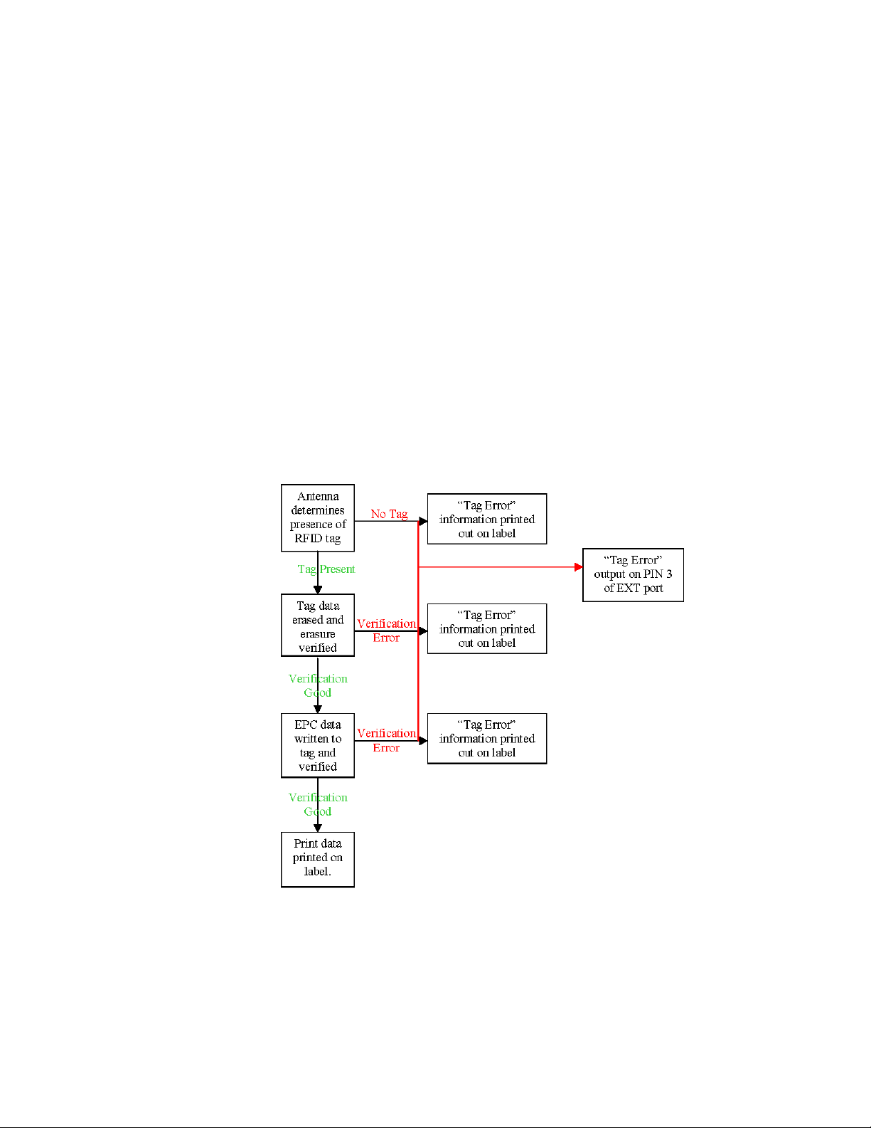
The following process details the steps involved in writing to the EPC tag:
SATO RFID User Guide PN 9001147B Page 1
Page 4
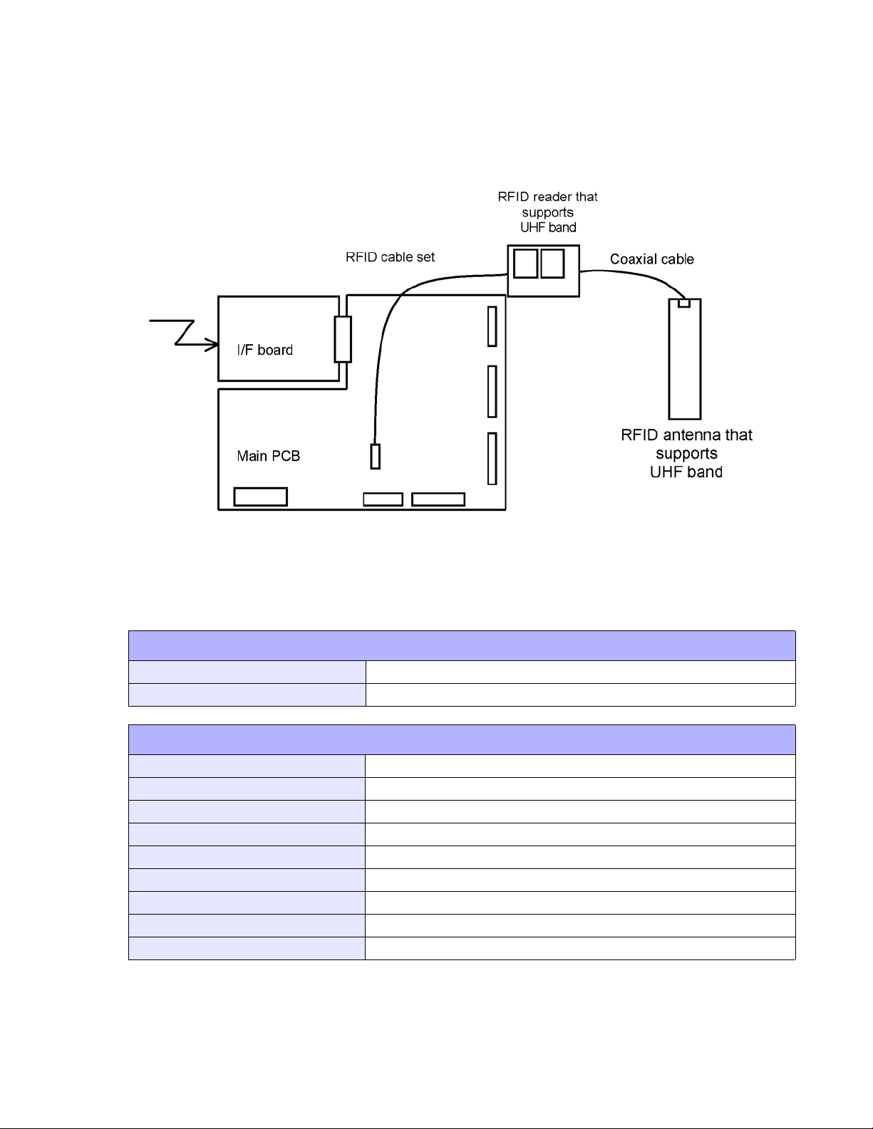
RFID HARDWARE CONFIGURATION
The RFID hardware kit is comprised of the: RFID Module, RFID Antenna w/coaxial cable, RFID
Cable Set. The figure below displays configuration:
RFID ANTENNA SPECIFICATIONS
Module 85.47 x 53.98 x 7.62 mm (sealed in a shield case)
Antenna 16 x 118 x 1.6 mm
RFID READER SPECIFICATIONS
Name ALR-9930 (module by Alien Technology)
Frequency 902-928 MHz
Communication System Frequency hopping spectrum dispersion
Transmission Output Maximum 1W (30 dBm), Uses less than 250mW
Transmission Output Control 14dB and 0.1 dB steps
Communications Protocol EPC global UHF, Class 1
Source Voltage 5-6 V +/- 3%
Demand Current Maximum 650 mA
Electrostatic Voltage Resistance ESD Class 2
SATO RFID User Guide PN 9001147B Page 2
Page 5

EXT CONNECTOR
The EXT Port pin-out information for the RFID has changed slightly to accomodate the addition
of a “tag error” output. The tag error output is available on PIN 3. The “Ribbon Out” output,
formerly found at PIN 3, has been combined with the “Label Out” output on PIN 1. PIN 1 will now
provide a “Media Out” (ribbon and/or label) error. The PIN 3 signal polarity is the same for “tag
Error” as it was for “Ribbon Out” previously.
PIN ASSIGNMENTS
PIN DESCRIPTION DIRECTION
1 Media Out - Pin goes low (0V) when label or ribbon is out. Output
2 Signal Ground Reference
RFID Tag Error - Pin goes low (0V) when a bad RFID tag is identified and
3
begins to feed from the printer.
Printer Error - Pin goes low (0V) when the printer detects an error condition
4
such as head open, receiving buffer full or when the user specified number of
RFID errors has been reached.
5 Print Start - The printer will print one label when this pin is pulled to ground. Input
End Print - Used to drive an applicator or other external device requiring
6
synchonization with the print cycle.
7 Reprint - Prints a duplicate of the last label when this signal is received. Input
8 Reserved. Input
9 Offline - Pin goes low (0V) when the printer is offline. Output
Ribbon Near End - Pin goes high when the amount of ribbon on the unwind
10
11 Reserved Output
12 +24 +/- 10% @ 2A - Power for external devices. Output
13 Vcc - +5V Output
14 Frame Ground Reference
shaft is approximately 46 feet (14 m). The ouput will be low when the ribbon
is gone.
Output
Output
Output
Output
NOTE: If backfeed is set to occur “After Print”, the RFID tag will be in the
improper location relative to the antenna and the tag will not be programmed.
SATO RFID User Guide PN 9001147B Page 3
Page 6

RFID SPECIFIC MENU ITEMS
The LCD menu items specific to RFID are located in the Service Mode menu area. To reach the
Service Mode menu area, power the printer on while pressing and holding the LINE and FEED
keys. Release the keys upon hearing the printer beep. Press the LINE key twice, and then the
FEED key to enter the Service Mode menu items.
The following LCD menus are specific to RFID operation:
RFID MENUS
DISPLAY DESCRIPTION
Sets the number of times the printer will attempt to re-encode
and re-print data following a Tag Error. The printer will enter the
error mode when the entered number of retries has been met.
The default is 00. The range is 00 to 99.
Sets the printer response after the “REPRINT CONT” has
been reached. When “STOP” is selected, the printer will enter
an error state that can be cleared by pressing the LINE key.
Selecting “AUTO” will allow the error to be cleared by the next
PRINT START signal from the applicator.
Sets the RFID Tag Error output for either a level signal or a
pulse signal. The default is Level.
When “PULSE” is selected in the previous menu, the length of
the pulse can be set through this menu item. The default is
100ms. The range is 100 to 500 ms increments.
Selecting “YES” prints the message “RFID TAG ERROR” and
a diagonal slash through the label. For the slash to print to the
size of the label, the Media Size command (<ESC>A1) must
be included in the data stream. Selecting “NO” prints only the
message “RFID TAG ERROR” at the top of the label. The
default is YES.
SATO RFID User Guide PN 9001147B Page 4
Page 7

LABEL GALLERY
Open Label Gallery Plus. The following main menu screen will appear.
Click on FILE of the upper task bar and then click on NEW from the menu options. The Label
Setup Wizard screen for Select Printer will display as shown below.
Click on the menu scroll-down arrow and select the RFID printer driver relative to the printer of
use. Make other screen selections as deemed necessary and then click on the NEXT button until
the Label Dimensions screen appaers. The Label Dimensions screen is shown below.
SATO RFID User Guide PN 9001147B Page 5
Page 8

Move the mouse cursor to each Label Dimension field and enter the required dimensions to
properly format for the print job at hand. Click on the FINISH button when complete and the
following Label Gallery screen will appear with a blank label present.
Click on DATA of the upper task bar and then select the RF DATA option. The following RF TAG
screen will appear.
SATO RFID User Guide PN 9001147B Page 6
Page 9

Click on the scoll-down arrow for the Type field and select the Alien - EPC (class 1) 64 bit menu
option or the type of inlay desired.
Next, click on the scoll-down arrow for the Data Type field and select either ASCII or Hex
Encoded String option.
ASCII Allows the data to be entered as full ASCII table and the
software changes over to HEX when sending it to the
printer. For a 64 bit tag selection, eight (8) digits must
be used and for a 96 bit selection, twleve (12) digits
must be used.
HEX Allows the data to entered using 0 through 9 and A
through F. The exact data is sent to the printer’s chip.
For a 64 bit tag selection, sixteen (16) digits must be
used and for 96 bit selection, twenty-four (24) digits
must be used.
Note that this data may also be substituted with a variable previously created in Label Gallery by
selecting the Variable option for the Data Source ratio.
EPC encoding translators may also be used by selecting that relative box on the screen. When
checked, select the type of EPC encoding you wish to use and then fill in the data values which
show up as shown on the following screen.
SATO RFID User Guide PN 9001147B Page 7
Page 10

Click on the OK button when complete and the label will show up on the next screen with the
RFID inlay outlined around the label. Refer to the screen below.
SATO RFID User Guide PN 9001147B Page 8
Page 11

Populate the label with label fields. Refer to the Label Galley Manual’s Help Files for assistance
as required.
Once complete, click on FILE on the upper task bar, select the Print option and then enter the
desired print quantity. The Print screen is displayed below.
SATO RFID User Guide PN 9001147B Page 9
Page 12

EPC CODE WRITE DESIGNATION COMMAND
FUNCTION
FORMAT
PARAMETER
EXAMPLE
NOTES
Writes EPC code in RFID supply that supports EPC code.
<ESC>IP0n.nnn
n = Data to be written (16 bytes fixed for 64 bit inlays) or (24 bytes
fixed for 96 bit inlays).
To write 64-bit EPC code “8000 0000 4000 0001” for label issuance in
RFID supply that supports EPC code:
<ESC>A
<ESC>V50<ESC>H50<ESC>BD3020654912345678904
<ESC>IP08000000040000001
<ESC>Q1
<ESC>Z
Printing of multiple tags (QTY > 1) is available with this command. If
data is written to an RFID tag, labels are printed after sent EPC data
and encoded EPC data are automatically checked.
If EPC code writing could not be carried out (i.e. bad tag), a tag error
label is printed and an output is sent via EXT Port, PIN 3.
Data other than 0 to 9 and A to F will be considered a command error.
If used without print data, this command will not cause a label to feed
in the case of a successful tag encode.
EPC CODE READ DESIGNATION COMMAND
FUNCTION
FORMAT
RETURN STATUS
FORMAT
RETURN STATUS LIST
EXAMPLE
NOTES
Reads information of RFID supply supporting EPC code.
<ESC>IP1
STX (02H) . EPC code . ETX (03H)
STX (02H) = Starting code: 1 byte.
EPC Code = EPC Code; 16 bytes fixed.
ETX (03H) = Ending code: 1 byte fixed.
<ESC>A<ESC>IP1<ESC>Z
If “8000 0000 4000 0001” is recorded in RFID supply that supply that
supports EPC code:
02 = Starting code
38 30 30 30 30 30 30 30 34 30 30 30 30 30 30 31 EPC
03 = Ending code.
NOTE: In actuality, all data is continuous without spaces.
This command cannot be combined with another command to
designate.
This command cannot be received during printing.
If the connection is closed before all status’ are returned to the host, the
tag data will not be correctly returned.
SATO RFID User Guide PN 9001147B Page 10
 Loading...