

Page 1
v.G1.5
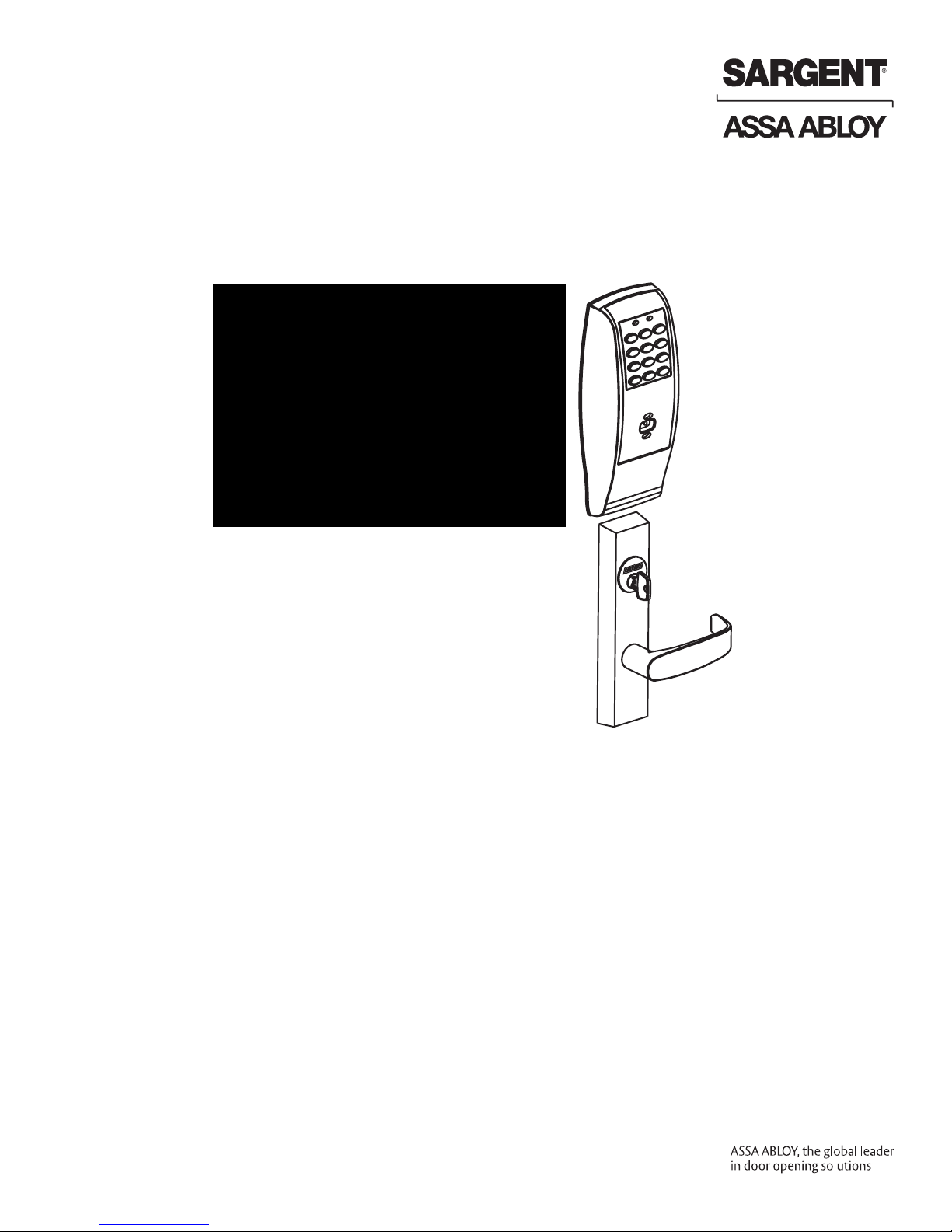
Profile
& LK Exit Device
Installation Instructions
A7856C
10/16
Copyright 2016, Sargent Manufacturing Company, an ASSA ABLOY Group company.
All rights reserved. Reproduction in whole or in part without the express written
permission of Sargent Manufacturing Company is prohibited.
Page 2

Page 3
Table of Contents
1
Warning ............................................................................3
2
General Description
3
Specifications
4
Features
5
Parts Breakdown
............................................................................ 4
................................................................... 4
.......................................................... 4
8877/8878 x ET x Profile Series Rim Exit Device
8977/8978 x ET x Profile Series Mortise Exit Device
Installation Instructions: Rim 8877/8878
6
Installation Instructions: Mortise 8977/8978
7
8
RF Technology Lock
9
Wiring Options
10
Operational Check
................................................................ 22
........................................................ 21
.......................................................... 27
........................ 9
............. 5
....... 7
................ 15
Warning
1
This device complies with Part 15 of the FCC Rules. Operation is subject to the following two conditions: (1) this
device may not cause harmful interference, and (2) this device must accept any interference received, including
interference that may cause undesired operation.
Note: This equipment has been tested and found to comply with the limits for a Class B digital device, pursuant to
Part 15 of the FCC Rules. These limits are designed to provide reasonable protection against harmful interference
in a residential installation.
This equipment generates, uses and can radiate radio frequency energy and if not installed and used in accordance
with the instructions, may cause harmful interference to radio communications. However, there is no guarantee that
the interference will not occur in a particular installation. If this equipment does cause harmful interference to radio
or television reception, which can be determined by turning the equipment off and on, the user is encouraged to try
to correct the interference by one or more of the following measures:
• Reorient or relocate the receiving antenna
• Increase the separation between the equipment and receiver
• Connect the equipment into an outlet on a circuit different from that to which the receiver is connected
• Consult the dealer or an experienced TV technician for help
This Class B digital apparatus complies with Canadian ICES-003.
Cet appareil numérique de la classe B est conforme avec la norme NMB-003 du Canada.
Copyright © 2016, Sargent Manufacturing Company, an ASSA ABLOY Group company. All rights reserved.
Reproductions in whole or in part without express written permission of Sargent Manufacturing Company is prohibited.
10/31/16
1-800-810-WIRE • www.sargentlock.com • A7856C
To comply with “Fire Listed” doors, the batteries must be replaced with alkaline batteries only.
!
Do not install batteries if controller is powered by external power supply.
Warning SARGENT Mfg. Co. locksets utilizing a door position switch (DPS)
!
are not rated for, or intended for use in life safety applications.
Changes or modifications to this unit not expressly approved by the party
responsible for compliance could void the user’s authority to operate the equipment.
Page 4

Profile Series v.G1.5 Rim Exit Device
General Description
2
The SARGENT Profile v.G1.5 Rim and Mortise Exit Devices are designed for areas which require stand-alone
authorized entry. They consist of a self-contained microprocessor-controlled keypad with non-volatile memory.
The keypad holds a total of 100(LK)/2000 (G1-LU, G1-PK, G1-PA, G1-TU, G1-TP, G1-TA) different user codes.
User codes 01 and 02 are utilized for Master and Supervisory Codes, respectively. SARGENT mortise locks are
designed with quality components to provide high security, performance and durability.
• The Profile v.G1.5 Series provides enhanced software and hardware features.
• New v.G1.5 controllers replace v.G1 controllers. Product is still ordered as “G1-” prefix.
Controllers are labeled “G1.5”.
• This product is operated by six (6) “AA” alkaline batteries.
Specifications
3
Profile Series Rim Exit
• Latch – 3/4” throw, stainless steel
• Outside motor driven Exit Trim (“ET”) lever
controlled by keypad
• Push bar retracts latch from inside
• Fire stop provided on all lever handle designs
• Profile Series exit devices furnished for 1-3/4”
doors
• UL Listed
• Accepts all SARGENT rim cylinders (8877 only)
• Key retracts latch (8877 only)
• Available in ET lever handle designs only
4
Features
• Non-volatile memory
• Motor driven, battery operated
• Battery operated with 6 “AA” Alkaline
• Low battery alert–4 chirps after code entry
• External remote “request to enter”
• Master, Emergency or Supervisory code will
unlock door when low battery has expired
• 100 (LK) or 2000 (G1-LU, G1-PK, G1-PA,
G1-TU, G1-TP, G1-TA) users
• Programming done at keypad or with a DTD
(Data Transfer Device) using SoloPlus™
software and a Laptop /PC (G1-TA and
G1-TP require software)
SoloPlus™ works with PalmPilot; SofLink™
Plus software not supported with DTD.
Profile Series Mortise Exit
• Latch – 3/4” throw, anti-friction, brass
• Outside motor driven Exit Trim (“ET”) lever
controlled by keypad
• Push bar retracts latch from inside
• Fire stop provided on all lever handle designs
• Profile Series exit devices furnished for
1-3/4” doors
• UL Listed
• Accepts all SARGENT mortise cylinders (8977 only)
• Key retracts latch (8977 only)
• Available in ET lever handle designs only
• RF Fob and Proximity Card, Tag, and
Fob are optional
• Operates utilizing any one to six digit code.
• Digits may be repeated and codes may start
with zero
• Cylinder override
• Entry of three wrong User Codes disables all
codes for ten seconds. Yellow LED on solid
• Piezo horn can be heard with each keystroke or
turned off by Master or Supervisory Code
• Last 15 transactions can be output to portable
print via infrared link (LK Only)
• Last 2000 (Except LK) transactions can be
output to PC via SofLink™ Plus Software
Copyright © 2016, Sargent Manufacturing Company, an ASSA ABLOY Group company. All rights reserved.
Reproductions in whole or in part without express written permission of Sargent Manufacturing Company is prohibited.
10/31/16
4 1-800-810-WIRE • www.sargentlock.com • A7856C
Page 5
Profile Series v.G1.5 Rim Exit Device
Parts Breakdown
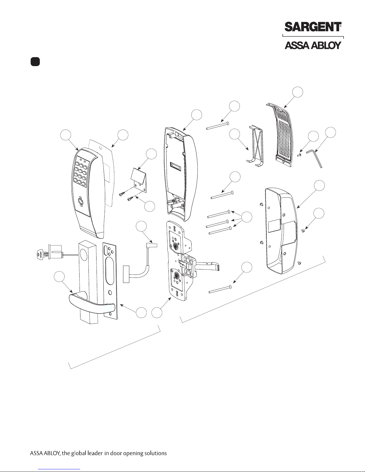
5
8877/8878 x ET x Profile Series Rim Exit Device
3
12
2
1
9
17
6
7
10
8
12
11
11
Inside
5
4
14
15
Outside
16
13
Items included with 8877 and 8878 Rim Exit Device:
• Outside Escutcheon with Keypad
• Outside motorized ET Trim Assembly
• Exit Device (Chassis & Rail Assembly)
• Rim cylinder for 8877
• Inside Escutcheon with Circuit Board and Battery Pack
• 6 “AA” alkaline batteries
• Screw Packs
1-800-810-WIRE • www.sargentlock.com • A7856C 5
Copyright © 2016, Sargent Manufacturing Company, an ASSA ABLOY Group company. All rights reserved.
Reproductions in whole or in part without express written permission of Sargent Manufacturing Company is prohibited.
10/31/16
Page 6

Profile Series v.G1.5 Rim Exit Device
Parts Breakdown 8877/8878 x ET x Profile Series Rim Exit Device (Continued)
ITEM PART NO.
1 52-2839 Outside Escutcheon (Prox Only) Assembly (G1-PA, G1-TA) 1
52-2474 Outside Escutcheon (Key Pad Only) Assembly (LK)
52-2838 Outside Escutcheon (Key Pad/Prox) Assembly (G1-LU, G1-PK, G1-TU, G1-TP)
52-2704 Key Pad and Proximity Assembly (G1-LU, G1-PK, G1-TU, G1-TP) 1
52-2432 Key Pad/Proximity Bezel Assembly w/ Harness (LK)
52-2706 Proximity Only Assembly (G1-PA, G1-TA) 1
68-1397 Outside Escutcheon Housing Only 1
52-0176 Outside Escutcheon End Cap 1
2 52-2460 Inside Escutcheon Assembly with 100 User Controller (LK) 1
52-2833 Inside Escutcheon Assembly with 2000 User Controller (G1-LU)
52-2834 Inside Escutcheon Assembly with Prox/Key Pad Controller (G1-PA, G1-PK)
52-2836 Inside Escutcheon Assembly (Key Pad Only) with RF Technology Controller (G1-TU)
52-2835 Inside Escutcheon Assembly (Key Pad/Prox or Prox Only) with RF Technology Controller
(G1-TA, G1-TP)
68-1396 Inside Escutcheon Housing Only 1
52-0175 Inside Escutcheon End Cap Only 1
52-2441 100 User Controller Assembly (LK) 1
52-2783 2000 User Controller Assembly (G1-LU)
52-2784 2000 User Controller Assembly (G1-PA, G1-PK)
52-2786
52-2785 2000 User (Key Pad Only) Controller Assembly w/ RF Technology (G1-TU)
3 52-0170 Battery Cover 1
52-2309 Battery Cover – RF Technology (G1-TU,G1-TP, G1-TA)
4 01-1212 Security Screw 1
5 01-0297 Security Tool 1
6 52-0033 Fire Stop Plate 1
7 01-1500 Fire Stop Screws #8 x 1/2” Type “AB” Phillips Pan Head Self Tap 2
8 52-0253 Battery Keeper 1
52-0344 Battery Keeper – RF Technology (G1-TU, G1-TP, G1-TA)
Consult Factory
9
Consult Factory
10
11 01-4451 ET Through-bolts 2
12 77-0685 Escutcheon Through-bolts 2
13 68-4261 Center Case Assembly LHRB & RHRB (Std.)
68-4263 Center Case Assembly LHRB (12-) & RHRB (12-) 2
14 68-0406 Chassis Cover 1
15 97-0052 Chassis Cover Screws 4
52-2425 Screw Pack (Includes item numbers 5,6,7,15) 1
Copyright © 2016, Sargent Manufacturing Company, an ASSA ABLOY Group company. All rights reserved.
16 52-0263 Gasket, ET 1
Reproductions in whole or in part without express written permission of Sargent Manufacturing Company is prohibited.
17 68-1400 Gasket, Escutcheon 1
10/31/16
6 1-800-810-WIRE • www.sargentlock.com • A7856C
01-0803 Battery Alkaline (“AA” Cell) (Not Shown) 6
2000 User (Key Pad/Prox or Prox Only) Controller Assembly w/ RF Technology (G1-TA, G1-TP)
Motorized ET Lever Trim (with Key and Cylinder) 1
Motor and Harness Assembly 1
DESCRIPTION REQ’D
Page 7
Profile Series v.G1.5 Mortise Exit Device
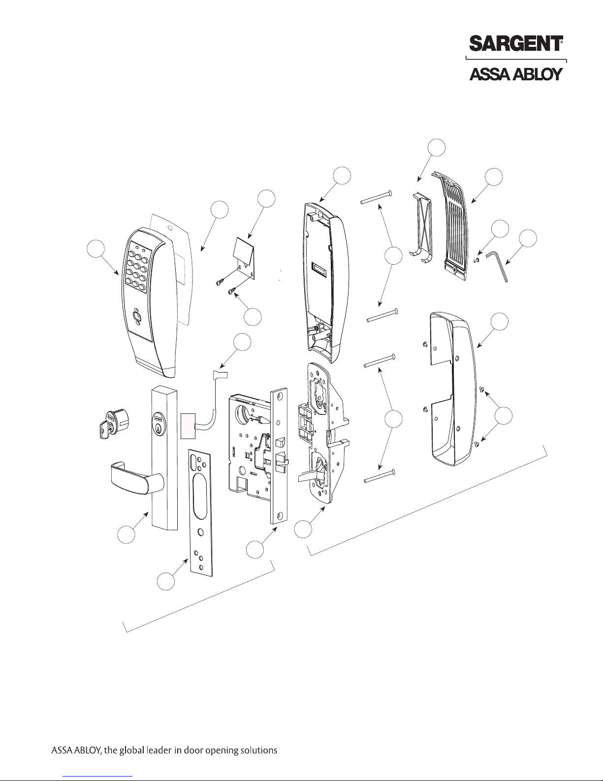
Parts Breakdown (continued)
8977/8978 x ET x Profile Series Mortise Exit Device
8
2
6
3
19
4
5
1
7
11
13
12
16
17
10
18
Outside
15
Inside
14
Items included with 8977 and 8978 Mortise Exit Device:
• Outside Escutcheon with Keypad
• Outside Motorized ET Trim Assembly
• Exit Device (Chassis, Rail Assembly and Mortise Lock)
• Mortise Cylinder for 8977
• Inside Escutcheon with Circuit Board and Battery Pack
• 6 “AA” alkaline batteries
• Screw Packs
1-800-810-WIRE • www.sargentlock.com • A7856C 7
Copyright © 2016 Sargent Manufacturing Company, an ASSA ABLOY Group company. All rights reserved.
Reproductions in whole or in part without express written permission of Sargent Manufacturing Company is prohibited.
10/31/16
Page 8
Profile Series v.G1.5 Mortise Exit Device
Parts Breakdown 8977/8978 x ET x Profile Series Mortise Exit Device (Continued)
ITEM PART NO.
1 52-2839 Outside Escutcheon (Prox Only) Assembly (G1-PA, G1-TA) 1
52-2838 Outside Escutcheon (Key Pad/Prox) Assembly (G1-LU, G1-PK, G1-TU, G1-TP)
52-2704 Key Pad and Proximity Assembly (G1-LU, G1-PK, G1-TU, G1-TP) 1
52-2432 Key Pad/Proximity Bezel Assembly w/ Harness (LK)
52-2706 Proximity Assembly (G1-PA, G1-TA) 1
68-1397 Outside Escutcheon Housing Only 1
52-0176 Outside Escutcheon End Cap Only 1
2 52-2460 Inside Escutcheon Assembly with 100 User Controller (LK) 1
52-2833 Inside Escutcheon Assembly with 2000 User Controller (G1-LU)
52-2834 Inside Escutcheon Assembly with Prox/Key Pad Controller (G1-PA, G1-PK)
52-2836 Inside Escutcheon Assembly (Key Pad Only) with RF Technology Controller (G1-TU)
52-2835 Inside Escutcheon Assembly (Key Pad/Prox or Prox Only) with RF Technology Controller
(G1-TA, G1-TP)
68-1396 Inside Escutcheon Housing Only 1
52-0175 Inside Escutcheon End Cap Only 1
52-2441 Enclosure Assembly (LK) 1
52-2783 Enclosure Assembly (G1-LU) 1
52-2784 Key Pad/Prox or Prox Only Controller Assembly (G1-PA, G1-PK) 1
52-2786
52-2785 2000 User (Key Pad Only) Controller Assembly w/ RF Technology (G1-TU) 1
3 52-0170 Battery Cover 1
52-2309 Battery Cover – RF Technology (G1-TU,G1-TP, G1-TA) 1
4 01-1212 Security Screw 1
5 01-0297 Security Tool 1
6 52-0033 Fire Stop Plate 1
7 01-1500 Fire Stop Screws #8 x 1/2” Type “AB” Phillips Pan Head Self Tap 2
8 52-0253 Battery Keeper 1
52-0344 Battery Keeper – RF Technology (G1-TU, G1-TP, G1-TA)
9 52-2425 Screw Pack (Includes item numbers 5, 6, 7, 12, 13) (not shown) 1
Consult Factory
10
Consult Factory
11
12 01-4451 ET Through-bolts 2
13 77-0685 Escutcheon Through-bolts 2
14 68-2172 Center Case Assembly LHRB (Standard and 12-) 1
68-2173 Center Case Assembly RHRB (Standard and 12-) 1
15 99-2401 Mortise Lock LHRB 1
99-2402 Mortise Lock RHRB 1
16 68-0407 Chassis Cover 1
17 97-0052 Chassis Cover Screws 4
18 68-1400 Chassis Gasket 1
Copyright © 2016 Sargent Manufacturing Company, an ASSA ABLOY Group company. All rights reserved.
Reproductions in whole or in part without express written permission of Sargent Manufacturing Company is prohibited.
19 52-0263 ET gasket 1
10/31/16
01-0803 Batteries - Alkaline (“AA” Cell) (not shown) 6
8 1-800-810-WIRE • www.sargentlock.com • A7856C
2000 User (Key Pad/Prox or Prox Only) Controller Assembly w/ RF Technology (G1-TA, G1-TP)
Motorized ET Lever Trim 1
Motor and Harness Assembly 1
DESCRIPTION REQ’D
1
Page 9
Profile Series v.G1.5 Rim Exit Device
Installation Instructions: 8877/8878 Rim Type Exit Device
6
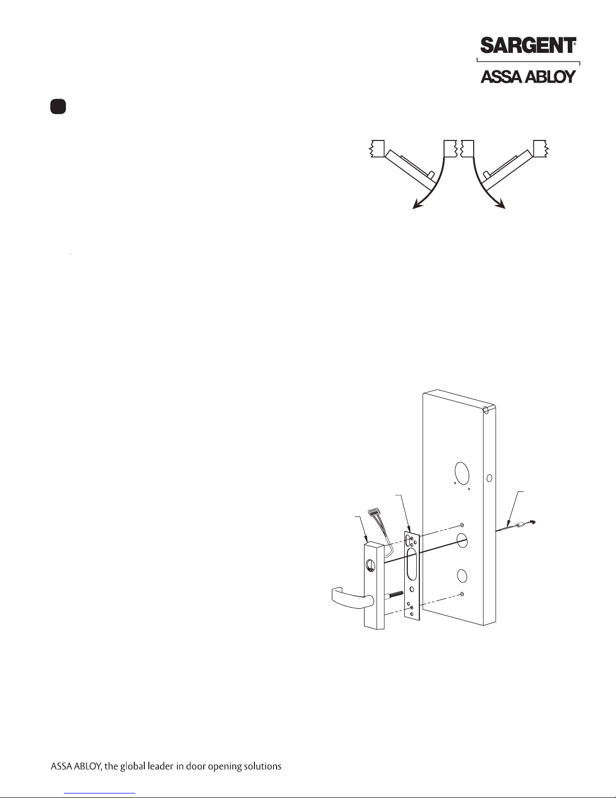
Step #1 – Prepare Door
A. Verify Hand and Bevel of Door
• This device is non-handed.
• Door should be fitted and hung.
• Verify box label for size of exit device and function.
B. Door Preparation
If using a mullion, install prior to installing hardware.
Doors should be pre-prepped.
Prepare door according to appropriate template:
• Exit installation instructions A6770
• Door Manufacturer’s Template 4640 (Metal and Wood)
Note: Wood door has additional cutout if installation includes a cylinder.
Step #2 – Position Exit Trim (ET)
For exterior applications, use ET gasket (P/N 52-0263)
to seal between ET escutcheon and outside door surface.
1A. For wood doors: Route ET wire harness through the cylinder
hole, out the other side, and through the wire run channel to
the controller cutout.
1B. For metal doors: Route ET wire harness
through the cylinder hole and door
and out the controller cutout.
2. Position and hold ET trim on the door.
3. Connector from ET harness connects
to connector from chassis (Fig. 2)
Exit trim Gasket
(Exterior Applications)
Left Hand
Reverse Bevel
LHRB
Inside
Outside
Fig. 1
Right Hand
Reverse Bevel
RHRB
ET Wire Harness
(from motor)
Outside of Door
Exit trim
Fig. 2
1-800-810-WIRE • www.sargentlock.com • A7856C 9
Copyright © 2016, Sargent Manufacturing Company, an ASSA ABLOY Group company. All rights reserved.
Reproductions in whole or in part without express written permission of Sargent Manufacturing Company is prohibited.
10/31/16
Page 10

Profile Series v.G1.5 Rim Exit Device
Outside of Door
Inside of Door
Fig. 4B
Step #3 – Mount Exit Device Chassis (Inside Trim)
1. Route ET harness along track cutout for wood doors and
through access hole for metal doors.
2. Position exit chassis carefully.
Do not pinch the wire harness.
3. Engage ET spindle in hub of exit device chassis.
4. Secure the exit chassis with through-bolts
to the ET trim using (2) 1/4 -20 x 2-3/8”
flat head machine screws.
Inside of Door
(2) 1/4 x 2-3/8” Flathead
Machine Screws
ET Motor
Harness
Step #4 – Install Cylinder and Secure Chassis
For devices without cylinder, skip this step.
1. Insert cylinder into ET control (Fig. 4A).
2. Mate cylinder tailpiece into hub of exit device chassis.
3. Make sure ET harness is clear of cylinder and cylinder tailpiece.
4. Secure cylinder to exit chassis using (2) #12-24 x 1-7/8”
connecting screws (Fig 4B).
5. Fasten exit chassis to door using:
• (4) #10 wood screws for wood doors (or)
• (4) #10-24 machine screws for metal doors.
6. Position cylinder so that the SARGENT
logo is right-side up (Fig. 4C).
Exit Chassis
Fig. 3
Inside of Door
(4) #10 Wood or
#10-24 Machine
Screws
(2) #12-24 x 1-7/8”
Flat Head Screws
(Connecting Cylinder)
Fig. 4C
Incorrect
Fig. 4A
Correct
Copyright © 2016, Sargent Manufacturing Company, an ASSA ABLOY Group company. All rights reserved.
Reproductions in whole or in part without express written permission of Sargent Manufacturing Company is prohibited.
10/31/16
10 1-800-810-WIRE • www.sargentlock.com • A7856C
Fig. 4B
Page 11

Profile Series v.G1.5 Rim Exit Device
Step #5 – Exterior Door Options
A. Fire Stop Plate (P/N 52-0033)
Fire-rated doors require a fire stop plate on the
outside of the door (Fig.5A).
1. Drill (2) 1/8" x 1-1/4" deep holes in the door if not
already present.
Refer to template for fire-stop prep locations.
2. Attach with flap up and out using (2) #8 x 1/2”
self-tapping screws for wood
and metal doors.
B. Weather Conduit (P/N 52-2847)
Ribbon Cable Hole
Install weather conduit on NON FIRE-RATED
exterior doors only.
1. Carefully insert the weather conduit
into the ribbon cable hole on
the inside of the door (Fig 5B).
2. Place the O-ring around the
weather conduit on the outside
and up against the door (Fig. 5C).
Outside of Door
O-Ring
Fig.5C
Step #6 – Gasket Installation (for Exterior Doors)
For exterior applications, use a gasket between
escutcheon and outside door surface:
1. Carefully remove the backing from the gasket.
2. Apply gasket to escutcheon carefully.
a. Starting in one place, press the adhesive side
of the gasket firmly against the escutcheon.
b. Work around the escutcheon, pressing the sticky side
of the gasket firmly against the escutcheon edge.
c. The gasket should be aligned so that all edges
of the escutcheon are covered.
4. Attach escutcheon to the door.
Fig.5B
Fig. 5A
Outside of Door
Fig. 6A
Fig. 6B
1-800-810-WIRE • www.sargentlock.com • A7856C 11
Copyright © 2016, Sargent Manufacturing Company, an ASSA ABLOY Group company. All rights reserved.
Reproductions in whole or in part without express written permission of Sargent Manufacturing Company is prohibited.
10/31/16
Page 12

Profile Series v.G1.5 Rim Exit Device
Step #7 – Install Outside Escutcheon
For 12- fire rated exit devices, feed keypad
ribbon cable/connector from outside of door
through the gasket then
Fire
Stop
Plate
Weatherseal
Gasket
Ribbon
Cable
fire stop plate (Fig. 7).
For non-fire 12- exit devices, feed keypad
ribbon cable/connector through gasket then
through the conduit hole in door.
Outside of Door
Fig. 7
Step #8 – Connect and Position Outside Escutcheon Wires
Images shown represent installation without gasket. If gasket is necessary, refer to Step #6.
Before the controller is attached to the door:
1. Attach the reader assembly ribbon cable to the inside face of the controller assembly (side that
faces towards the door when mounted (Fig. 8B).
Note: Install ribbon cable with side marked TOP facing up. (Fig. 8A).
2. Attach the ground wire to the bottom of the controller assembly (E1, Fig. 8A).
3. Connect the exit connector to the bottom of the controller (TB1, Fig. 8B).
If Hardwiring is required, go to “Hardwire Wiring Options” on page 14.
4. Place extra wire inside door hole and/or outside escutcheon,
being careful not to pinch wires.
Connectors go on only one way.
Do not offset connectors,
and make sure they are
completely seated.
Outside
escutcheon
Reader Cable
1
2
Ground Wire
Outside Escutcheon
Copyright © 2016, Sargent Manufacturing Company, an ASSA ABLOY Group company. All rights reserved.
Reproductions in whole or in part without express written permission of Sargent Manufacturing Company is prohibited.
10/31/16
Fig. 8A
12 1-800-810-WIRE • www.sargentlock.com • A7856C
3
Reader Cable
Ground
Wire
1
P1
1
2
TB1
Motor
Connector
TB1
3
Power/Data
E3
Connector
2
TB2
RedBlack
3
Fig. 8B
Page 13

Profile Series v.G1.5 Rim Exit Device
Step 9 – Install and Secure Inside Escutcheon
1. Secure the inside escutcheon using two #8-32
screws through top and bottom of the
escutcheon (Fig. 9).
Thread into outside escutcheon.
2. Straighten escutcheons and tighten securely,
being careful to avoid pinching wires.
Battery Cover
Step #10 – Install and Remove Batteries*
Battery Keeper
Security
Screw
Security Tool
(P/N 01-0297, Included
Fig. 9
A. Install Batteries and Keeper
1. Place (6) “AA” batteries into the compartment, being careful to properly align polarity (Fig. 10A).
2. To install battery keeper, insert the tabs on the bottom of the keeper into the battery compartment slots
and press the keeper tightly against batteries and inserting tabs into bottom slots.
• For RF technology, use RF Technology lock information 20.
IMPORTANT: * Do not install batteries if controller is powered by external power supply.
• Test for proper operation before closing door.
B. Remove Battery Keeper
To remove the battery keeper, pull the keeper away from the batteries (Fig. 10B).
+
-
Battery Keeper
+
+
Tip Out
-
+
Bottom Tabs
(Battery Keeper)
Fig. 10A
Keeper Tabs
Fig. 10B
1-800-810-WIRE • www.sargentlock.com • A7856C 13
Copyright © 2016, Sargent Manufacturing Company, an ASSA ABLOY Group company. All rights reserved.
Reproductions in whole or in part without express written permission of Sargent Manufacturing Company is prohibited.
10/31/16
Page 14

Step #11 – Install Inside Cover
1. Attach inside cover to escutcheon making
sure to line up tabs with retaining
slots in cover.
2. Secure with security screw using
provided security tool Fig. 11).
Profile Series v.G1.5 Rim Exit Device
Tabs
Retaining Slots
Fig. 11
For information about the RF Technology versions (G1-TU, G1-TP, G1-TA),
refer to “RF Technology Lock” on page 21.
For information about Wiring, refer to “Wiring Options” starting on page 22.
For information about the Testing,
refer to “Operational Check” on page 27.
Step #12 – Install Rail Assembly
Attach rail assembly according to Exit Installation Instructions A6770.
Copyright © 2016, Sargent Manufacturing Company, an ASSA ABLOY Group company. All rights reserved.
Reproductions in whole or in part without express written permission of Sargent Manufacturing Company is prohibited.
10/31/16
14 1-800-810-WIRE • www.sargentlock.com • A7856C
Page 15

Profile Series v.G1.5 Mortise Exit Device
7
Installation Instructions: 8977/8978 Mortise Exit Device
Step #1 – Prepare Door
A. Verify Hand and Bevel of Door
• This device is non-handed.
• Door should be fitted and hung.
• Verify box label for size of exit device and function.
B. Door Preparation
Prior to installation, all holes must be free of burrs, debris and sharp edges.
Prepare door according to appropriate template:
• Exit installation instructions A6770
• Wood door template A7457 ships with product.
• Door manufacturer’s template 4641 (metal and wood)
Left Hand
Reverse Bevel
“LHRB”
Inside of DoorOutside of Door
Inside
Outside
Fig. 1A
Right Hand
Reverse Bevel
“RHRB”
Hole for Ribbon Cable from
Controller to Keypad
Inside of Cylinder Hole
Thumb Turn Lever Hole
Lever Handle Hole
Mortised
Pocket
Pre-drilled and/or
Tapped Holes (2 places)
Through-bolt Hole
Outside Cylinder Hole
(76 and 78 Functions)
Lever Handle Hole
Copyright © 2016 Sargent Manufacturing Company, an ASSA ABLOY Group company. All rights reserved.
Reproductions in whole or in part without express written permission of Sargent Manufacturing Company is prohibited.
1-800-810-WIRE • www.sargentlock.com • A7856C 15
10/31/16
Page 16

Profile Series v.G1.5 Mortise Exit Device
Step #2 - Install (ET) Exit Trim and Mortise Lock
1. For exterior applications, use ET gasket (52-0263)
to seal between ET escutcheon and outside
door surface (Fig. 2A).
2. Slide mortise lock into door and securely
fasten with (2) flat head screws (Fig. 2B).
3. Route ET harness through square wire
cutout and out other side of door.
4. Place ET control on door with spindle
inserted through mortise lock (Fig. 2A).
Outside of Door
Outside of Door
1
ET gasket
(part number
52-0263)
3
Fig. 2A
Showing Wood Door Template
Without Cylinder
4
Fig. 2B
Showing Wood Door Template
With Cylinder
Copyright © 2016 Sargent Manufacturing Company, an ASSA ABLOY Group company. All rights reserved.
Reproductions in whole or in part without express written permission of Sargent Manufacturing Company is prohibited.
10/31/16
16 1-800-810-WIRE • www.sargentlock.com • A7856C
2
Page 17

Profile Series v.G1.5 Mortise Exit Device
Outside of Door
Inside of Door
Fig. 4B
Step #3 - Install Exit Chassis
1. Route ET harness along track cutout for wood doors or through
access hole for metal doors (Fig. 3A).
2. Mount exit chassis carefully. Do not pinch harness wires.
3. Position exit chassis on door with lever arm under
rear section of mortise lock (Fig. 3B).
4. Secure chassis and ET with (2) 1/4-20 x
2-3/8” flat head machine screws (Fig. 3A).
4. Fasten exit chassis to door using:
• (4) #10 wood screws for wood doors (or)
• (4) #10-24 machine screws for metal doors.
Inside of Door
(4) #10 Wood or
#10-24 Machine
Screws
Latchbolt
Fig. 3A
Fig. 3C
Step #4 – Install Cylinder and Secure Chassis
For devices without cylinder, skip this step.
1. Insert cylinder into ET control (Fig. 4A).
2. Mate cylinder tailpiece into hub of exit device chassis.
3. Make sure ET harness is clear of
cylinder and cylinder tailpiece.
4. Secure cylinder to exit chassis
using (2) #12-24 x 1-7/8”
connecting screws (Fig 4B).
5. Position cylinder so that the SARGENT
logo is right-side up (Fig. 4C).
Chassis
Lever
Fig. 3B
Lever arm
Inside of Door
(2) #12-24 x 1-7/8”
Connecting Screws
Correct
Incorrect
Fig. 4C
Fig. 4A
Fig. 4B
1-800-810-WIRE • www.sargentlock.com • A7856C 17
Copyright © 2016 Sargent Manufacturing Company, an ASSA ABLOY Group company. All rights reserved.
Reproductions in whole or in part without express written permission of Sargent Manufacturing Company is prohibited.
10/31/16
Page 18

Profile Series v.G1.5 Mortise Exit Device
Step #5 – Exterior Door Options
A. Fire Stop Plate (P/N 52-0033)
Fire-rated doors require a fire stop plate on the outside of the door (Fig.5A).
1. Drill (2) 1/8" x 1-1/4" deep holes in the door if not already present.
Refer to template for fire-stop prep locations.
2. Attach with flap up and out using (2)
#8 x 1/2” self-tapping screws for
wood and metal doors.
B. Weather Conduit (P/N 52-2847)
Ribbon Cable Hole
Install weather conduit on NON FIRE-RATED
exterior doors only.
1. Carefully insert the weather conduit
into the ribbon cable hole on
the inside of the door (Fig 5B).
2. Place the O-ring around the
weather conduit on the outside
and up against the door (Fig. 5C).
Outside of Door
O-Ring
Fig.5C
Step #6 – Gasket Installation (for Exterior Doors)
For exterior applications, use a gasket between
escutcheon and outside door surface:
1. Carefully remove the backing from the gasket.
2. Apply gasket to escutcheon carefully.
a. Starting in one place, press the adhesive side
of the gasket firmly against the escutcheon.
b. Work around the escutcheon, pressing the
sticky side of the gasket firmly against the
escutcheon edge.
c. The gasket should be aligned so that all edges
of the escutcheon are covered.
4. Attach escutcheon to the door.
Fig.5B
Outside of Door
Fig. 6A
Fig. 5A
Copyright © 2016 Sargent Manufacturing Company, an ASSA ABLOY Group company. All rights reserved.
Reproductions in whole or in part without express written permission of Sargent Manufacturing Company is prohibited.
10/31/16
18 1-800-810-WIRE • www.sargentlock.com • A7856C
Fig. 6B
Page 19

Profile Series v.G1.5 Mortise Exit Device
Step #7 – Install Outside Escutcheon
For 12-fire rated exit devices, feed keypad
ribbon cable/connector from outside of
door through the gasket then fire stop
Fire
Stop
Plate
Weatherseal
Gasket
Ribbon
Cable
plate (Fig. 7).
For non fire-12-exit devices, feed keypad
ribbon cable/connector through gasket
then through the conduit hole in door.
Outside of Door
Fig. 7
Step #8 – Connect and Position Outside Escutcheon Wires
Images shown represent installation without gasket. If gasket is necessary, refer to Step #6.
Before the controller is attached to the door:
1. Attach the reader assembly ribbon cable to the inside face of the controller assembly (side that
faces towards the door when mounted (Fig. 8B).
Note: Install ribbon cable with side marked TOP facing up. (Fig. 8A).
2. Attach the ground wire to the bottom of the controller assembly (E1, Fig. 8A).
3. Connect the exit connector to the bottom of the controller (TB1, Fig. 8B).
If Hardwiring is required, go to “Hardwire Wiring Options” on page 14.
4. Place extra wire inside door hole and/or outside escutcheon,
being careful not to pinch wires.
Connectors go on only one way.
Do not offset connectors,
and make sure they are
completely seated.
Outside
escutcheon
Reader Cable
1
2
Ground Wire
Outside Escutcheon
Fig. 8A
3
Reader Cable
Ground
Wire
P1
1
1
2
TB1
Motor
Connector
TB1
3
1-800-810-WIRE • www.sargentlock.com • A7856C 19
Power/Data
E3
Connector
2
TB2
Fig. 8B
RedBlack
Copyright © 2016 Sargent Manufacturing Company, an ASSA ABLOY Group company. All rights reserved.
Reproductions in whole or in part without express written permission of Sargent Manufacturing Company is prohibited.
10/31/16
Page 20

Profile Series v.G1.5 Mortise Exit Device
Step 9 – Install and Secure Inside Escutcheon
1. Secure the inside escutcheon using two #8-32
screws through top and bottom of the
escutcheon (Fig. 9).
Thread into outside escutcheon.
2. Straighten escutcheons and tighten securely,
being careful to avoid pinching wires.
Battery Cover
Battery Keeper
Security
Screw
Security Tool
(P/N 01-0297, Included
Fig. 9A
Step #10 – Install and Remove Batteries*
A. Install Batteries and Keeper
1. Place (6) “AA” batteries into the compartment, being careful to properly align polarity (Fig. 10A).
2. To install battery keeper, insert the tabs on the bottom of the keeper into the battery compartment slots
and press the keeper tightly against batteries and inserting tabs into bottom slots.
• For RF technology, use RF Technology lock information “RF Technology Lock” on page 20.
IMPORTANT: * Do not install batteries if controller is powered by external power supply.
• Test for proper operation before closing door.
B. Remove Battery Keeper
To remove the battery keeper, pull the keeper away from the batteries (Fig. 10B).
+
-
Battery Keeper
+
+
Tip Out
-
+
Bottom Tabs
Copyright © 2016 Sargent Manufacturing Company, an ASSA ABLOY Group company. All rights reserved.
Reproductions in whole or in part without express written permission of Sargent Manufacturing Company is prohibited.
10/31/16
20 1-800-810-WIRE • www.sargentlock.com • A7856C
(Battery Keeper)
Fig. 10A
Keeper Tabs
Fig. 10B
Page 21

Step #11 – Install Inside Cover
1. Attach inside cover to escutcheon making
sure to line up tabs with retaining
slots in cover.
2. Secure with security screw using
provided security tool (Fig. 11).
For information about the RF Technology versions (G1-TU, G1-TP, G1-TA),
refer to “RF Technology Lock” in next section.
For information about Wiring, refer to “Wiring Options” starting on page 21.
Profile Series v.G1.5 Mortise Exit Device
Tabs
Retaining Slots
Fig. 11
For information about the Testing,
refer to “Operational Check” on page 26.
Step #12 – Install Rail Assembly
Attach rail assembly according to Exit Installation Instructions A6770.
RF Technology Lock
8
Installation for the RF Technology Lock for
G1-TU, G1-TA, G1-TP is, for the most part,
installed as described in section 6.
In addition:
The antenna board must be carefully
moved to access the upper through-bolt
screw. Care should be taken to prevent
damage to the antenna retaining tabs
during this process (Fig. 12).
1. Press the two tabs away from the
antenna board and lift the board
off the mounting posts.
2. Insert the flat head through-bolt and
secure the escutcheon in place.
3. After tightening the top through-bolt,
replace the antenna board by placing
it on the mounting posts and pressing
into the retaining tabs.
Antenna
Board
Mounting
Posts
Flathead
Through-bolt
Antenna
Board
Antenna Board
Retaining Tabs
Fig. 12
Copyright © 2016 Sargent Manufacturing Company, an ASSA ABLOY Group company. All rights reserved.
Reproductions in whole or in part without express written permission of Sargent Manufacturing Company is prohibited.
10/31/16
21 1-800-810-WIRE • www.sargentlock.com • A7856C
Controller
Assembly
Page 22

Profile Series v.G1.5/LK Exit Device
Wiring Options
9
Hardwiring options include one or a combination of Forced/Propped Door, Hard Power and/or Remote
Unlock (REX). Refer to the examples on the following pages:
1. Forced/Propped Door Option (DM-).
2. Hard Power and Remote Unlock (91-).
3. Hard Power and Remote Unlock (-91), with Forced Propped Door (DM-).
Important
1. Caution: Disconnect all input power before beginning installation to prevent electrical shock and
equipment damage.
2. Installer must be a trained, experienced service person.
3. All wiring must comply with applicable local electrical codes, ordinances and regulations.
Installation Notes
1. With new applications, an ElectroLynx® door harness with 8 and 4 pin connectors will be
pre-installed inside door by Assa Abloy door manufacturer when specified during ordering process.
2. Wiring to pigtail harness is per facility wiring requirement.
ElectroLynx® connector terminations and wire colors all match.
3. If door does not have an ElectroLynx® type door harness, cut connectors off product and hard-wire,
or consult factory for appropriate mating harness.
ElectroLynx® Connector System Notes
The system is designed to be installation friendly with connectors
from the electric hinge through the door to the rail. The only wiring
required is to the loose wires on the pigtail harness
assembly on the frame side of the electric hinge.
IMPORTANT:
The plug and receptacle connectors are designed to mate and lock
together as shown in the figure. Plug the connectors into each other
with the locking mechanism aligned as indicated.
Do NOT force connectors on any other way.
ElectroLynx®
As part of their promise to provide innovative, fast and effective, and higher security
solutions to their customers, ASSA ABLOY Group companies offer ElectroLynx, a
universal quick-connect system that simplifies the electrification of the door opening.
ElectroLynx® is a registered trademark of ASSA ABLOY, Inc.
Receptical
Locking Mechanism
Plug
1-800-810-WIRE • www.sargentlock.com • A7856C 22
Copyright © 2016, Sargent Manufacturing Company, an ASSA ABLOY Group company. All rights reserved.
Reproductions in whole or in part without express written permission of Sargent Manufacturing Company is prohibited.
10/31/16
Page 23

Profile Series v.G1.5/LK Exit Device
ElectroLynx Lock Wire Connections
A
Door Position Switch (DPS)
Install the SARGENT 3287 Door Status Switch according to
instructions included in the kit.
Wire the 3287 Door Status Switch to the ElectroLynx frame harness and to the door status wires:
1. Connect the common wire of the switch to the common wire
of the harness.
2. Connect the normally open wire of the switch to the door
position wire of the harness.
Note: The third wire (normally closed) of the 3287 Door
Status Switch is not used for this type of system.
Before the controller is attached to the door (Fig. 1A):
1. Attach the reader cable to the controller.
2. Attach the connector from the lock into the bottom
of the circuit board (TB2, Fig. 3B).
3. Plug the ground wire into the bottom of the controller assembly (E1, Fig. 3B).
4. Route the connector from the raceway through the top opening between the controller and the escutcheon, along the battery keeper, back under the bottom opening between the controller and escutcheon and
attach at the bottom of the controller.
Note: Connectors go on only one way.
Do not offset connectors and make sure they are completely seated.
D
B
C
A
Fig. 1
Inside
Escutcheon
(Front)
Inside
4
1
1
3
2
2
Inside of Door
Escutcheon
(Back)
4
Fig. 1A
4
Copyright © 2016, Sargent Manufacturing Company, an ASSA ABLOY Group company. All rights reserved.
Reproductions in whole or in part without express written permission of Sargent Manufacturing Company is prohibited.
10/31/16
1-800-810-WIRE • www.sargentlock.com • A7856C 23
Page 24

Option #1 – Forced / Propped Door (DM-)
Installation
1. ElectroLynx® System Wiring Instructions (Fig. 1, 1A and Fig. 2):
a. Look for the mating part on ASSA ABLOY doors and frames.
b. Plug in all connectors during product installation (Fig. 2).
c. Hard wire door status switch as shown
2. Non-ElectroLynx® System Wiring Instructions (Fig. 1 and Fig. 2):
a. Cut the 4-pin connector off the Forced/Propped harness and hard wire to
non-ElectroLynx® two conductor door harness.
b. DM- requires two conductors.
c. Hard wire door harness to power transfer device.
d. Hard wire door status switch to power transfer device.
Profile Series v.G1.5/LK Exit Device
C
D
Door Status Switch
*Wire for switch contact closure
when door is opened - Typical
locations shown in Fig. 1
D
Door
B
A
Outside
Escutcheon
Fig. 1
1 - Red
2 - Black
3 - White (C)
4 - Green (*NC)
QC4A Electric Hinge
C B
With 4-pin connectors and pigtail harness
Inside
Escutcheon
(TB1) Motor
Connector
A
Ground
Forced/Propped Door
Tab E3
4-pin
Connector
Connector J4
4 - Tan
3 - Pink
DM- Prefix (52-3409)
Forced/Propped Door Harness
ElectroLynx Door Harness
With 8 and 4-pin connectors
(Harness location dependent on door type)
(TB2) Remote/Power
Unlock Connector
321
Forced/Propped Door Option
ElectroLynx Wiring System
1 - Red
2 - Black
Copyright © 2016, Sargent Manufacturing Company, an ASSA ABLOY Group company. All rights reserved.
Reproductions in whole or in part without express written vpermission of Sargent Manufacturing Company is prohibited.
10/31/16
3 - White
4 - Green
24 1-800-810-WIRE • www.sargentlock.com • A7856C
Fig. 2
Page 25

Profile Series v.G1.5/LK Exit Device
Option #2 – Remote Power and Remote Unlock (91-)
Installation
1. ElectroLynx® System Wiring Instructions (Fig. 1, 1A and Fig. 3):
D
B
C
A
a. Look for the mating part on ASSA ABLOY doors and frames.
b. Plug in all connectors during product installation (Fig. 3).
c. Hard wire hard power and/or remote unlock (REX) (Fig. 3).
2. Non-ElectroLynx® System Wiring Instructions (Fig. 1 and Fig. 3):
a. Cut the 8-pin connector off the Remote Power/Unlock
harness and hard wire to non-ElectroLynx® door harness.
b. Remote power requires three conductors and
remote unlock requires two conductors.
c. Hard wire door harness to power transfer device.
d. Hard wire door status switch to power transfer device.
*IMPORTANT: (6) “AA” batteries MUST be removed from
controller when using 3267 power supply.
Note: Refer to 3267 Power
Supply
Instruction Sheet A7477
120VAC L/N/G
* 3267 9VDC
Power Supply
Normally Open
Momentary Switch
(Remote Unlock
REX Option)
-9VDC
+9VDC
EGND
Fig. 1
Escutcheon
1 - Black
2 - Red
3 - White (NO)
4 - Green
5 - Orange (C)
6 - Blue
7 - Brown
8 - Yellow
Door
Outside
* Inside
Escutcheon
A
(TB1) Motor
Connector
Ground Tab E3
Fig. 3A
Remote Powering and Remote Unlocking
ElectroLynx Wiring System
(TB2) Remote/Power
Unlock Connector
+9V
(-)
REX
REX
1 - Red
2 - Black
Data Out
3 - White
4 - Orange
5 - Blue
1 2 3 4 5 6 7 8
91-Prefix (52-3010)
Remote Power and
Unlocking Harness
Data In
RTS
6 - Brown
7 - Yellow
EGND
8 - Green
1 - Black
2 - Red
3 - White (NO)
4 - Green
5 - Orange (C)
6 - Blue
7 - Brown
8 - Yellow
QC4A Electric Hinge
C B
With 8-pin connectors,
8 wires and pigtail harness
1-800-810-WIRE • www.sargentlock.com • A7856C 25
ElectroLynx Door Harness
With 8 and 4-pin connectors - Harness location is
dependent
on door type
Copyright © 2016, Sargent Manufacturing Company, an ASSA ABLOY Group company. All rights reserved.
Reproductions in whole or in part without express written permission of Sargent Manufacturing Company is prohibited.
10/31/16
Page 26

Profile Series v.G1.5/LK Exit Device
Option #3 – Hard Power/Remote Unlock (91-) Combined With Forced/Propped Door (DM-)
Installation
1. ElectroLynx® System Wiring Instructions (Fig. 1, 1A and Fig. 3):
D
B
C
A
a. Look for the mating part on ASSA ABLOY doors and frames.
b. Plug in all connectors during product installation (Fig. 3).
c. Hard wire hard power and/or remote unlock (REX) (Fig. 3).
2. Non-ElectroLynx® System Wiring Instructions (Fig. 1 and Fig. 3):
a. Cut the 8 and 4-pin connectors off the Remote Power/Unlock
harness and hard wire to non-ElectroLynx® door harness.
b. Remote power requires three conductors; and remote unlock
and DM- require two conductors.
c. Hard wire door harness to power transfer device.
d. Hard wire door status switch to power transfer device.
*IMPORTANT: (6) “AA” batteries MUST be removed from
controller when using 3267 power supply.
1 - Black
2 - Red
3 - White (NO)
4 - Green
5 - Orange (C)
6 - Blue
7 - Brown
8 - Yellow
120VAC L/N/G
* 3267 9VDC
Power Supply
Note: Refer to 3267 Power
Supply
Instruction Sheet A7477
-9VDC
+9VDC
EGND
Normally Open
Momentary Switch
(Remote Unlock
REX Option)
D
Fig. 1
Outside
Escutcheon
1 - Black
2 - Red
3 - White (NO)
4 - Green
5 - Orange (C)
6 - Blue
7 - Brown
8 - Yellow
1 - Red
2 - Black
3 - White (C)
4 - Green (*NC)
Door
* Inside
Escutcheon
A
(TB1) Motor
Connector
Ground Tab E3
Fig. 3A
Remote Powering and Remote Unlocking
ElectroLynx Wiring System
(TB2) Remote/Power
Unlock Connector
1 - Red
2 - Black
3 - White
4 - Green
+9V
(-)
REX
REX
Data Out
Data In
4 - Orange
5 - Blue
6 - Brown
321
RTS
7 - Yellow
1 2 3 4 5 6 7 8
1 - Red
2 - Black
3 - White
4 - Tan
3 - Pink
EGND
8 - Green
Copyright © 2016, Sargent Manufacturing Company, an ASSA ABLOY Group company. All rights reserved.
Reproductions in whole or in part without express written vpermission of Sargent Manufacturing Company is prohibited.
10/31/16
Door Status Switch
*Wire for switch contact closure
when door is opened - Typical
locations shown in Fig. 1
QC4A Electric Hinge
C B
With 8-pin connectors,
8 wires and pigtail harness
26 1-800-810-WIRE • www.sargentlock.com • A7856C
ElectroLynx Door Harness
With 8 and 4-pin connectors - Harness location is
dependent
on door type
Page 27

Profile Series v.G1.5/LK Exit Device
10
Operational Check
For devices with cylinders, insert key into cylinder and rotate.
Check to see if:
1. The key retracts the latch (if applicable).
Key should rotate freely.
2. Depress inside rail to retract latch.
3. Enter 1234* to unlock outside lever handle and retract latch.
4. If the lock is prox only (G1-PA) or RF Technology with Prox (G1-TA),
refer to keypad programming instructions A7716B or A7857.
~½”
1-800-810-WIRE • www.sargentlock.com • A7856C 27
Copyright © 2016, Sargent Manufacturing Company, an ASSA ABLOY Group company. All rights reserved.
Reproductions in whole or in part without express written permission of Sargent Manufacturing Company is prohibited.
10/31/16
Page 28

SARGENT Manufacturing Company
100 Sargent Drive
New Haven, CT 06511 USA
800-810-WIRE (9473) • www.sargentlock.com
Founded in the early 1800s, SARGENT® is a market leader in locksets, cylinders, door closers, exit devices,
electro-mechanical products and access control systems for new construction, renovation, and replacement applications.
The company’s customer base includes commercial construction, institutional, and industrial markets.
Copyright © 2016, Sargent Manufacturing Company, an ASSA ABLOY Group company. All rights reserved.
Reproduction in whole or in part without the express written permission of Sargent Manufacturing Company is prohibited.
ASSA ABLOY is the global leader in door opening solutions, dedicated to
satisfying end-user needs for security, safety and convenience.
A7856C-10/16
 Loading...