

Sargent SE LP10 7000 Series Installation Instructions Manual
7000
Series M1/ELR
A8239A
05/18
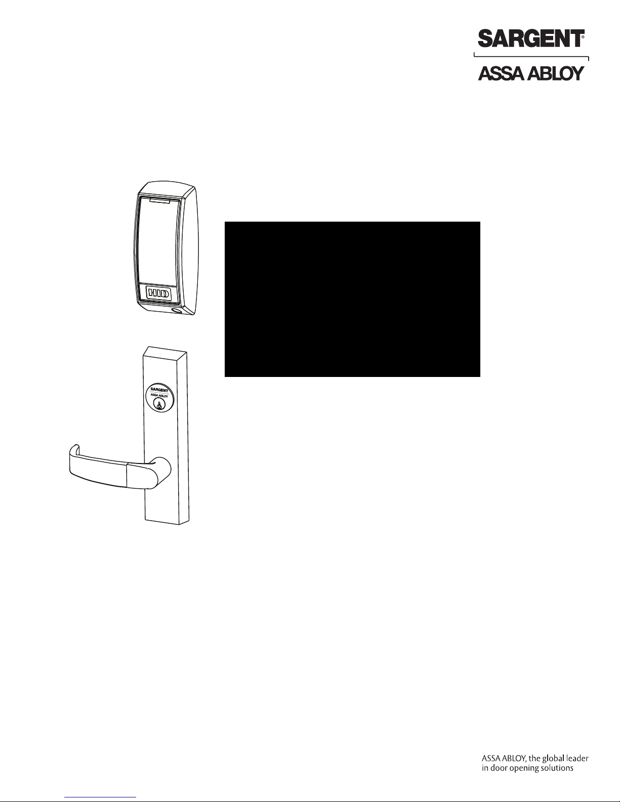
Multi-Point Lock
SE LP10
Reader
with
Installation Instructions
Copyright © 2018, Sargent Manufacturing Company, an ASSA ABLOY Group company.
All rights reserved. Reproduction in whole or in part without the express written
permission of Sargent Manufacturing Company is prohibited.

Table of Contents
1
Warning ...................................................................................3
2
General Description .................................................................4
3
Technical Specifications .........................................................4
4
Regulatory Specifications .......................................................4
5
Wiring Diagrams ......................................................................5
6
Parts Breakdown .....................................................................7
7
Installation Instructions .......................................................10
8
Concealed Door Position Switch Instructions (3287) ..........16
9
Mechanical Operational Check .............................................17
Electrical Operational Check .................................................17
10
1
Warning
This device complies with Part 15 of the FCC Rules. Operation is subject to the following two conditions: (1) this device
may not cause harmful interference, and (2) this device must accept any interference received, including interference that
may cause undesired operation.
Note: This equipment has been tested and found to comply with the limits for a Class B digital device, pursuant to Part
15 of the FCC Rules. These limits are designed to provide reasonable protection against harmful interference in a residential installation.
This equipment generates, uses and can radiate radio frequency energy and if not installed and used in accordance with
the instructions, may cause harmful interference to radio communications. However, there is no guarantee that the interference will not occur in a particular installation. If this equipment does cause harmful interference to radio or television
reception, which can be determined by turning the equipment off and on, the user is encouraged to try to correct the
interference by one or more of the following measures:
• Reorient or relocate the receiving antenna
• Increase the separation between the equipment and receiver
• Connect the equipment into an outlet on a circuit different from that to which the receiver is connected
• Consult the dealer or an experienced TV technician for help
This Class B digital apparatus complies with Canadian ICES-003.
Cet appareil numérique de la classe B est conforme avec la norme NMB-003 du Canada.
Contains FCC ID: U4A-SCSEHF
Contains IC: 6982A-SCSEHF
The term “IC:” before the radio certification number only signifies that Industry Canada technical specifications were
met. This Class B digital apparatus meets all requirements of the Canadian Interference Causing Equipment Regulations.
Operation is subject to the following two conditions: (1) this device may not cause harmful interference, and (2)
this device must accept any interference received, including interference that may cause undesired operation.
Cet appareillage numérique de la classe B répond à toutes les exigences de l’interférence canadienne causant des
règlements d’équipement. L’opération est sujette aux deux conditions suivantes: (1) ce dispositif peut ne pas causer
l’interférence nocive, et (2) ce dispositif doit accepter n’importe quelle interférence reçue, y compris l’interférence qui
peut causer l’opération peu désirée.
Changes or modifications to this unit not expressly approved by the party
responsible for compliance could void the user’s authority to operate the equipment.
Observe precautions for handling electrostatic sensitive devices.
!
Any retrofit or other field modification to a fire rated opening can potentially impact the fire rating of the opening, and
SARGENT Manufacturing makes no representations or warranties concerning what such impact may be in any specific
situation. When retrofitting any portion of an existing fire rated opening, or specifying and installing a new fire-rated
opening, please consult with a code specialist or local code official (Authority Having Jurisdiction) to ensure compliance
with all applicable codes and ratings.
Copyright © 2018, Sargent Manufacturing Company, an ASSA ABLOY Group company. All rights reserved.
Reproductions in whole or in part without express written permission of Sargent Manufacturing Company is prohibited.
05/31/18
3
A8239A • 800-810-WIRE (9473) • www.sargentlock.com
SE LP10 7000 Series Multi Point Lock
2
General Description
The SARGENT SE LP10 brings a new level of flexibility to our Integrated Wiegand access control solutions
for 7000 series multipoint locks. Featuring multiCLASS SE® Technology from HID Global®, the SE LP10
is ideal for mixed credential environments and enables easy migration to higher security credentials and
mobile access. Backed by SARGENT’s Grade 1 hardware, SE LP10 multipoint locks include an external
Door Position Switch (DPS) for door position monitoring, and other monitoring options, such as latchbolt
and lever monitoring, are available as add-ons. The SE LP10 reader provides visual (LED) and audible
indicators of lock state (locked/unlocked).
3
Technical Specifications
All SE LP10 Multi Point Locks
• Fire rated devices available
• Multi point lock furnished for 1-3/4” doors
• Fail safe or fail secure available
• Door Position Switch (DPS 3287) supplied
for monitoring
• 24VDC motor-operated ET Trim available
• Wire from EAC Panel to door must be shielded
with a drain terminated at EAC Panel controller
SE LP10 7000 Series Multi Point Lock
• Cylinder override available for 7000 CVR with
106 Series Auxiliary Control
4
Regulatory Specifications
• Outside lever can be controlled by multiple credential formats:
• 2.4 GHz credential compatibility
• Secure Identity Object
(Bluetooth Smart)
• 13.56 MHz credential compatibility:
• Secure Identity Object™ (SIO) on iCLASS Seos,
iCLASS SE/SR, MIFARE DESFire EV1 and MIFARE Classic
(on by default)
• Standard iCLASS Access Control Application, ISO14443A
(MIFARE) CSN, ISO14443B CSN, and ISO15693 CSN
• ISO14443A/B (PIV-compatible Transparent FASC-N read)
available with SE LP10-F
• NFC-enabled mobile phones
• 125 kHz credential compatibilty:
®
• HID Prox
, AWID, EM4102
™
(SIO) on Mobile IDs
SE LP10 M1 - ELR
12VDC System (ELR)
• Reader Draw = 200mA
(Reader is always 12VDC)
• 12VDC ELR Module Draw = 850mA
• Total System Draw = 1050mA
Wiring methods shall be in accordance with the National Electrical Code (ANSI/NFPA70), CSA 22.1, Canadian Electrical
Code (CEC), Part I, Safety Standard for Electrical Installations, local codes, and the authorities having jurisdiction.
Copyright © 2018, Sargent Manufacturing Company, an ASSA ABLOY Group company. All rights reserved.
Reproductions in whole or in part without express written permission of Sargent Manufacturing Company is prohibited.
SE LP10 M1 Non - ELR
12VDC / 24 VDC System (Non-ELR)
• Reader Draw = 200mA
(Reader is always 12VDC)
• Actuator Draw = 400mA inrush / 15mA
continuous @12 / 24 VDC
• Total System Draw = 600mA @ 12 / 24VDC
05/31/18
4
A8239A• 800-810-WIRE (9473) • www.sargentlock.com
SE LP10 7000 Series Multi Point Lock
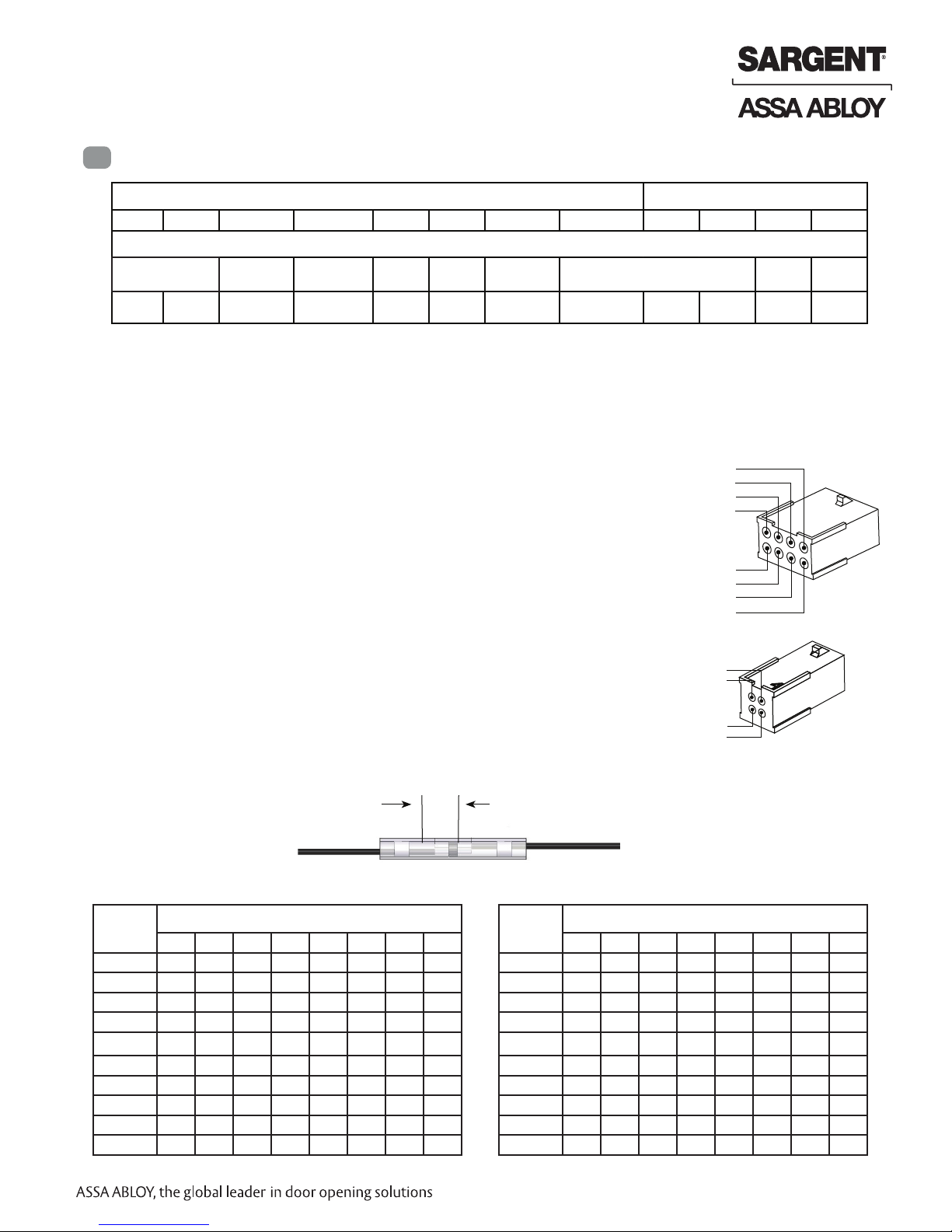
5
Wiring Diagrams
1-Black 2-Red 3-White 4-Green 5-Orange 6-Blue 7-Brown 8-Yellow 1-Violet 2-Gray 3-Pink 4-Tan
8 PIN CONNECTOR
4 PIN CONNECTOR
12VDC
(Reader)
NEG POS DATA_1 DATA_0 NO COM EGND
*Diagrams on following pages
WIEGAND WIEGAND RX RX EGND TAMPER
OPEN
COLLECTOR
The SE LP10 reader can be configured for various modes of LED and beeper operation. HID programming
cards are supported to configure the behavior for LED and beeper activity. Call 1-800-810-WIRE (9473) for
details. Along with the programming cards, the TAMPER wire can be connected within the panel and the
lock in order to enable some of the listed features.
Default Operation Mode:
• Red LED ‘ON’ when powered.
• Presenting a 13.56 MHz or 125 kHz credential causes LED to briefly
turn green and then return to red state.
• Presenting a FIPS 201 PIV credential causes LED to turn amber as
credential is authenticated. Reader emits a short beep when
credential is successfully read. Reference *Diagram #1.
Optional Operation Mode:
Connect selected TAMPER wire from reader to ElectroLynx cable pin 8.
Note: For fire rated doors solder sleeve (P/N 52-1373) to be applied to
desired lead 2.5” from base of reader. See diagram for application.
Connect Yellow TAMPER wire from ElectroLynx cable to desired EAC panel
control line.
As appropriate, use configuration card to activate desired mode on reader.
12/24 VDC
(LOCK RELAY)
NEG POS DPS DPS
PIN8 (Yellow – TAMPER)
PIN 6 (Blue – RX COM)
PIN 4 (Green – Data 0)
PIN 2 (Red – Reader POS)
PIN 1 (Black – Reader NEG)
PIN 3 (White – Data 1)
PIN 5 (Orange – RX NO)
PIN 7 (Brown - EGND)
PIN 4 (Tan – DPS COM)
PIN 2 (Gray – Lock POS)
PIN 1 (Violet – Lock NEG)
PIN 3 (Pink – DPS NC)
DPS
(NC)
DPS
(COM)
Note: When Yellow TAMPER wire is tied directly into EAC panel relay, no AC signals should be applied on wire or door reader performance will be impacted.
Overlap wires as shown. Use heat gun to set wires.
Wire Gauge Charts
Total
One-Way
Length of
Wire Run (ft)
1/4A 1/2A 3/4A 1A 1-1/4A 1-1/2A 2A 3A
100 20 18 16 14 14 12 12 10
150 18 16 14 12 12 12 10 —
200 16 14 12 12 10 10 — —
250 16 14 12 10 10 10 — —
300 16 12 12 10 10 — — —
400 14 12 10 — — — — —
500 14 10 10 — — — — —
750 12 10 — — — — — —
1,000 10 — — — — — — —
1,500 10 — — — — — — —
Load Current @ 12VDC
Strip 1/4”
Wire Gauge Charts
Total
One-Way
Length of
Wire Run (ft)
5
A8239A • 800-810-WIRE (9473) • www.sargentlock.com
1/4A 1/2A 3/4A 1A 1-1/4A 1-1/2A 2A 3A
100 24 20 18 18 16 16 14 12
150 22 18 16 16 14 14 12 10
200 20 18 16 14 14 12 12 10
250 18 16 14 14 12 12 12 10
300 18 16 14 12 12 12 10 —
400 18 14 12 12 10 10 — —
500 16 14 12 10 10 — — —
750 14 12 10 10 — — — —
1,000 14 10 10 — — — — —
1,500 12 10 — — — — — —
Load Current @ 24VDC
Copyright © 2018, Sargent Manufacturing Company, an ASSA ABLOY Group company. All rights reserved.
Reproductions in whole or in part without express written permission of Sargent Manufacturing Company is prohibited.
05/31/18
SE LP10 7000 Series Multi Point Lock
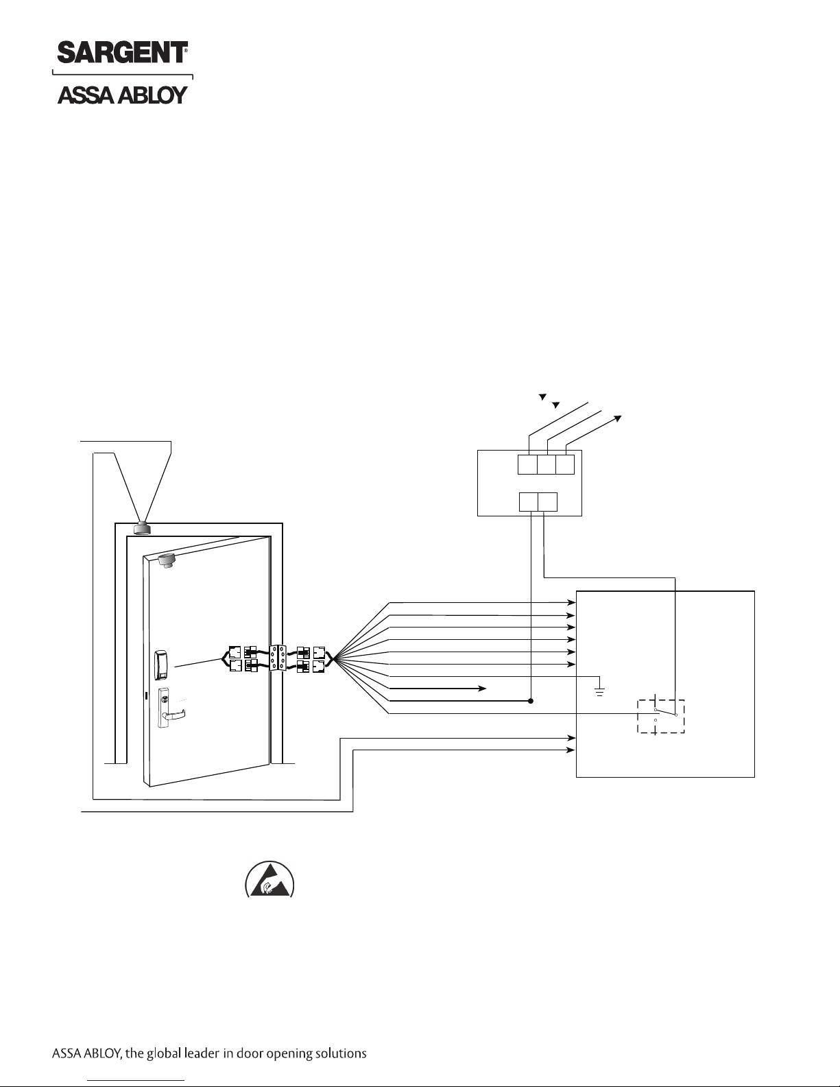
Typical SE LP10 Application Diagram (12/24VDC System)
DIAGRAM #1 – MODE 1: RED LED ‘ON’ WHEN POWERED
Standard Application Shown - For Alternative Applications Contact 1-800-810-WIRE (9473)
Reader Requires 5 to 16VDC Filtered and Regulated
12VDC System / 24VDC System
• Reader Draw = 200mA@12VDC
• Actuator Draw = 1A inrush / 600mA during retraction / 250 mA maintained
in dogged position @ 24VDC
Black (Hot)
White (Neutral)
Green (Gnd)
Input
H N G
12/24VDC
- +
SE LP10
Requires 12VDC
Green (NC)
White (C)
3287 Door
Position Switch
Lock body
Power Supply
(By Others)
120 VAC
READER NEG - Black, 1
QC12 Electric
Hinge From
SE LP10
Copyright © 2018, Sargent Manufacturing Company, an ASSA ABLOY Group company. All rights reserved.
Reproductions in whole or in part without express written permission of Sargent Manufacturing Company is prohibited.
McKinney
12 Conductor
ElectroLynx Harness
From McKinney
*IMPORTANT: Pin 7 must be tied to earth ground in the access control panel.
Failure to follow proper ESD safe grounding procedures could lead to equipment failure.
READER POS - Red, 2
DATA 1 - White, 3
DATA 0 - Green, 4
RX (NO) - Orange, 5
RX (COM) - Blue, 6
*EGND- Brown, 7
TAMPER - Yellow, 8
LOCK NEG - Violet, 9
LOCK POS - Gray, 10
Not Used
(-)
12/24VDC
(+)
DATA 1
DATA 0
RX (NO)
RX (COM)
DPS
DPS
Fail Safe
Operation
(NO) Fail
Secure
Operation
Electronic
Access Control
Panel
(By Others)
Use (NC) for
Lock
Relay
05/31/18
6
A8239A• 800-810-WIRE (9473) • www.sargentlock.com
 Loading...