

Page 1
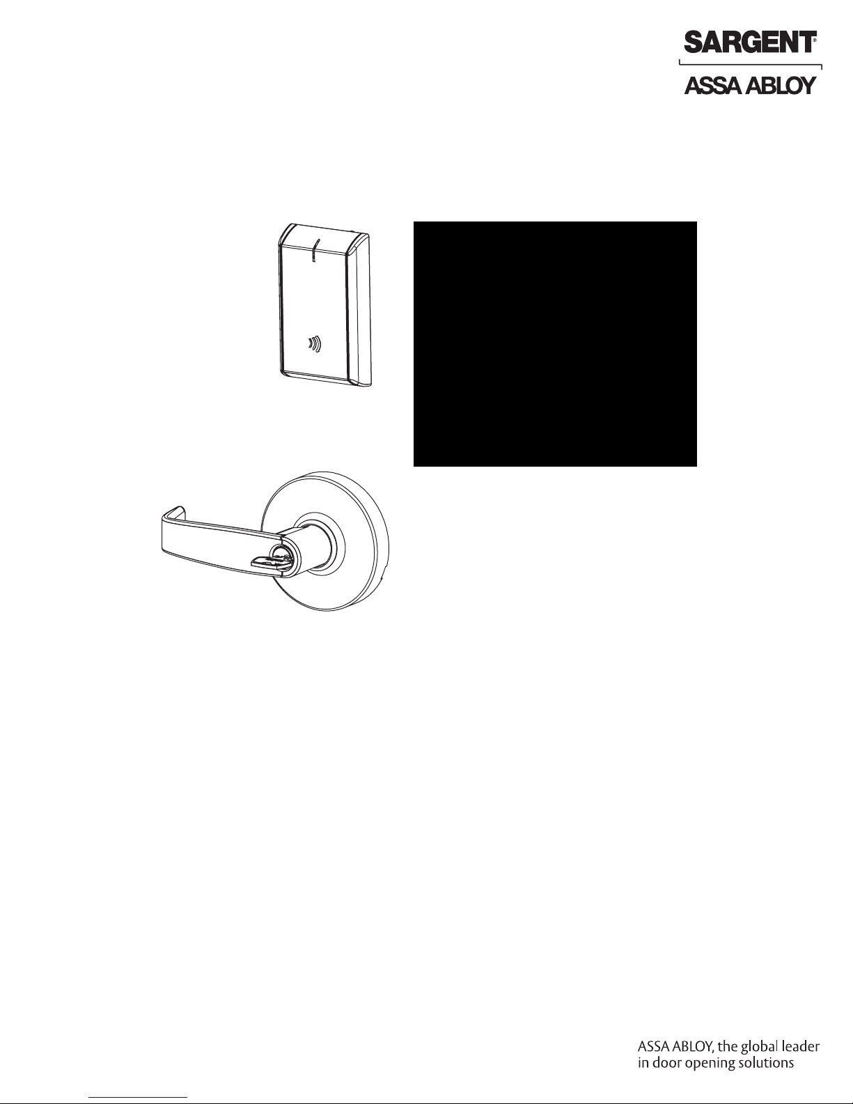
IN220
PoE
Cylindrical Lock
Installation Instructions
A8203A
04/16
Copyright 2016, Sargent Manufacturing Company, an ASSA ABLOY Group company.
All rights reserved. Reproduction in whole or in part without the express written
permission of Sargent Manufacturing Company is prohibited.
Page 2

Page 3
Table of Contents
1
Warning ...................................................................................3
2
General Description .................................................................4
3
Specifications ..........................................................................4
4
System Overview .....................................................................4
5
Parts Breakdown .....................................................................5
6
Installation Wiring ...................................................................7
7
Lock Installation ....................................................................11
Operational Check ................................................................23
8
1
Warning
FCC:
This equipment has been tested and found to comply with the limits for a Class B digital device, pursuant to Part 15 of the FCC Rules.
These limits are designed to provide reasonable protection against harmful interference in a residential installation. This equipment
generates, uses, and can radiate radio frequency energy and, if not installed and used in accordance with the instructions, may cause
harmful interference to radio communications. However, there is no guarantee that interference will not occur in a particular installation.
If this equipment does cause harmful interference to radio or television reception, which can be determined by turning the equipment off
and on, the user is encouraged to try to correct the interference by one or more of the following measures:
• Reorient or relocate the receiving antenna.
• Increase the separation between the equipment and receiver.
• Connect the equipment into an outlet on a circuit different from that to which the receiver is connected.
• Consult the dealer or an experienced radio/TV technician for help.
Changes or modifications to this device not expressly approved by ASSA ABLOY
could void the user’s authority to operate the equipment.
Industry Canada:
This Class B digital apparatus meets all requirements of the Canadian Interference Causing Equipment Regulations.
Operation is subject to the following two conditions: (1) this device may not cause harmful interference, and (2) this device must accept
any interference received, including interference that may cause undesired operation.
Cet appareillage numérique de la classe B répond à toutes les exigences de l’interférence canadienne causant des règlements
d’équipement. L’opération est sujette aux deux conditions suivantes: (1) ce dispositif peut ne pas causer l’interférence nocive, et (2) ce
dispositif doit accepter n’importe quelle interférence reçue, y compris l’interférence qui peut causer l’opération peu désirée.
“This equipment complies with FCC radiation exposure limits set forth for an uncontrolled environment. This equipment should be
installed and operated with minimum distance 20cm between the radiator and your body. This transmitter must not be co-located or
operating in conjunction with any other antenna or transmitter.”
Under Industry Canada regulations, this radio transmitter may only operate using an antenna of a type and maximum (or lesser)
gain approved for the transmitter by Industry Canada. To reduce potential radio interference to other users, the antenna type and
its gain should be so chosen that the equivalent isotropically radiated power (e.i.r.p.) is not more than that necessary for successful
communication.
Conformément à la réglementation d’Industrie Canada, le présent émetteur radio peut fonctionner avec une antenne d’un type et
d’un gain maximal (ou inférieur) approuvé pour l’émetteur par Industrie Canada. Dans le but de réduire les risques de brouillage
radioélectrique à l’intention des autres utilisateurs, il faut choisir le type d’antenne et son gain de sorte que la puissance isotrope
rayonnée équivalente (p.i.r.e.) ne dépasse pas l’intensité nécessaire à l’établissement d’une communication satisfaisante.
Any retrofit or other field modification to a fire rated opening can potentially impact the fire rating of the opening, and SARGENT
Manufacturing makes no representations or warranties concerning what such impact may be in any specific situation. When retrofitting
any portion of an existing fire rated opening, or specifying and installing a new fire-rated opening, please consult with a code specialist
!
or local code official (Authority Having Jurisdiction) to ensure compliance with all applicable codes and ratings.
To avoid possible damage from electrostatic discharge (ESD), some basic precautions should be used when handling
electronic components:
• Minimize build-up of static by touching and/or maintaining contact with unpainted metal surfaces such as
Copyright © 2016, Sargent Manufacturing Company, an ASSA ABLOY Group company. All rights reserved.
Reproductions in whole or in part without express written permission of Sargent Manufacturing Company is prohibited.
door hinges, latches, and mounting plates especially when mounting electronic components such as readers
and controllers onto the door
• Leave components (reader and controller) protected in their respective anti-static bags until ready
for installation
• Do not touch pins, leads or solder connections on the circuit boards
02/28/16
1-800-810-WIRE • www.sargentlock.com • A8203A
Page 4
IN220 Cylindrical Lock
2
General Description
The SARGENT IN220 Cylindrical lock combines superior aesthetics with the energy efficiency and
streamlined architecture of Power-over-Ethernet (PoE) access control. PoE-enabled access control
allows facilities to leverage existing network infrastructure for enhanced security and easier, more
cost-effective installations. Featuring multiCLASS SE
®
technology, it supports multiple credential
types, including mobile devices, for a future-proof solution that is convenient and secure.
3
Hardware Specifications
• Complete lockset with on-board memory
• ADA compliant
• Easily retrofits existing (cylindrical lock)
door preps
• Latch - 1/2” standard 3/4” throw fire-rated
double doors (optional) (41- prefix)
• Lock furnished for 1-3/4” doors.
For other thicknesses, consult factory.
• May be used for indoor and outdoor applications
• ANSI/BHMA A156.25 Listed Grade 1 Compliant
• Outside lever controlled by contactless reader
or mechanical cylinder
• Deadlocking latch - Stainless steel, non handed
NOTE: A weather-protective gasket is required for outdoor applications.
4
Electronic Specifications
• HID® multiCLASS SE® technology offers support
for the following credentials:
• 2.4 GHz credential compatibility:
™
• Secure Identity Object
Mobile IDs (Bluetooth Smart)
• 13.56 MHz credential compatibility:
• iCLASS®
• iCLASS SE® (SIO-enabled)
• iCLASS Seos
®
• SIO on MIFARE® Classic
• SIO on MIFARE® DESfire® EV1
• MIFARE® Classic
(SIO) on
• Input Power: PoE Class 1 Device, as defined by
IEEE 802.3af, requires less than 3.84 watts
over structured cabling
• Multiple time zone and holiday access scheduling
• First-in unlock or automatic unlock configuration,
based on specified time schedule
• 2,400 users per lock; 10,000 event audit trail
• Privacy button
• Power Requirements: 55VDC, 90mA
• UL Listed* - UL 294 Indoor Use
• CUL Listed - S319: Class 1
• UL 294 Access Control Performance Ratings:
• DESfire® EV1
• NFC-enabled mobile phones
Destructive Attack Level I
Line Security Level I
• 125 kHz credential compatibilty:
• HID Prox
®
Endurance Level IV
Standby Power Level I
*UL testing was conducted on product powered by
UL Listed model 9001GR/AC injector; manufactured
by Microsemi Corp.
Copyright © 2016, Sargent Manufacturing Company, an ASSA ABLOY Group company. All rights reserved.
Reproductions in whole or in part without express written permission of Sargent Manufacturing Company is prohibited.
04/30/16
4 1-800-810-WIRE • www.sargentlock.com • A8203A
Page 5
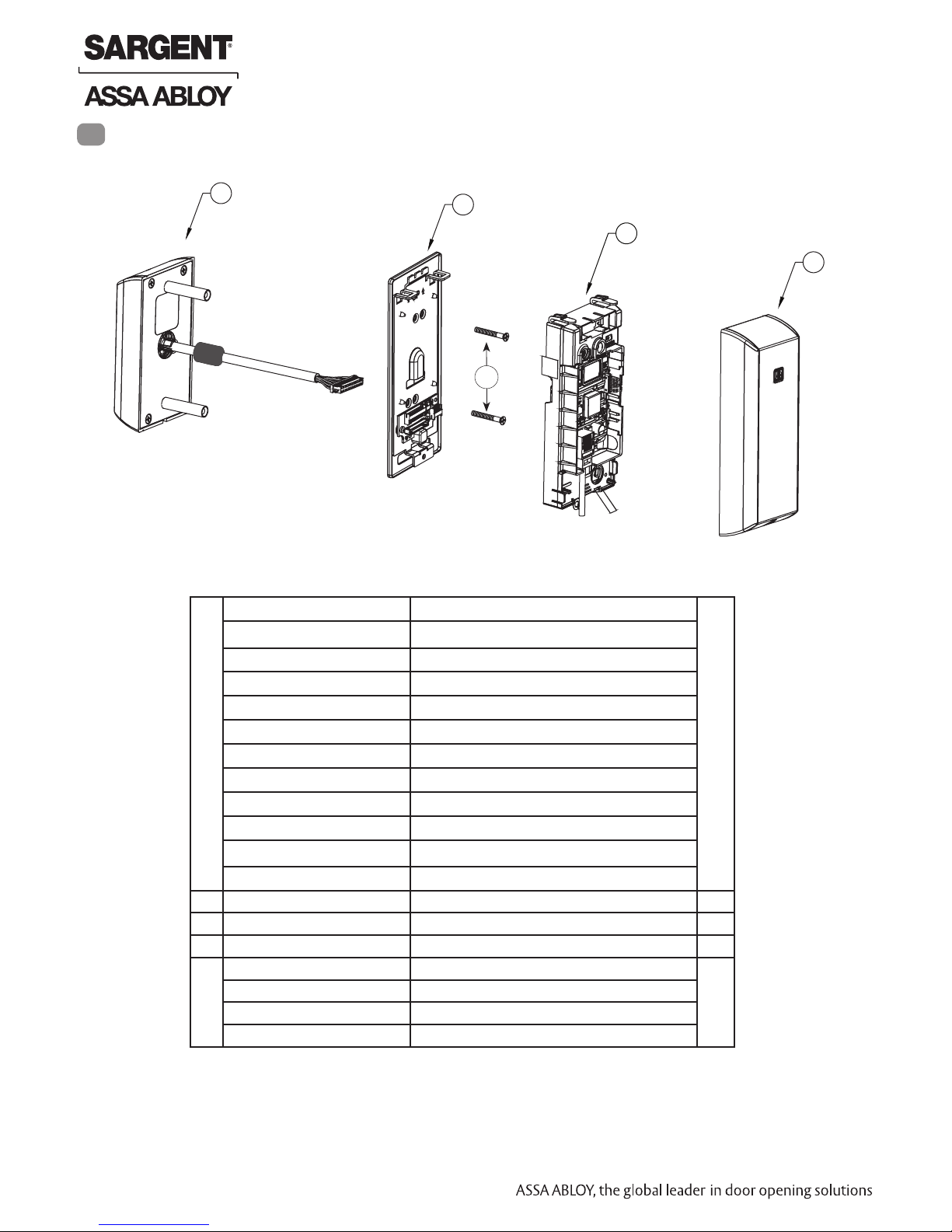
IN220 Cylindrical Lock
5
Parts Breakdown
1*
2
3
4
2a
PART NO./ORDER
ITEM
1 IN-220-EM01-[B*]IP-B Reader assembly - black plastic 1
STRING
IN-220-EM01-[B*]IP-W Reader assembly - white plastic
DESCRIPTION
QTY.
IN-220-EM01-[B*]IP-MB-xxx** Reader assembly - black plastic with metal trim
IN-220-EM01-[B*]IP-MW-xxx** Reader assembly - white plastic with metal trim
IN-220-EM01-[B*]IPS-B Reader assembly - black plastic
IN-220-EM01-[B*]IPS-W Reader assembly - white plastic
IN-220-EM01-[B*]CP-B Reader assembly - FeliCa - black plastic
IN-220-EM01-[B*]CP-W Reader assembly - FeliCa - white plastic
IN-220-EM01-[B*]CP-MB-xxx** Reader assembly - FeliCa - black plastic with metal trim
IN-220-EM01-[B*]CP-MW-xxx** Reader assembly - FeliCa - white plastic with metal trim
IN-220-EM01-[B*]IPS-MB-xxx** Reader assembly - black plastic with metal trim
IN-220-EM01-[B*]IPS-MW-xxx** Reader assembly - white plastic with metal trim
2 IN-220-EM04 Mounting plate assembly 1
2a Through-bolts (#8-32 x 1 1/4”) 2
3 IN-220-EM03 Controller assembly 1
4 IN-220-EM02-B Inside cover assembly - black plastic 1
IN-220-EM02-W Inside cover assembly - white plastic
IN-220-EM02-MB-xxx** Inside cover assembly - black plastic with metal trim
IN-220-EM02-MW-xxx** Inside cover assembly - white plastic with metal trim
*Specifying B indicates Bluetooth® Smart option when ordering
Copyright © 2016, Sargent Manufacturing Company, an ASSA ABLOY Group company. All rights reserved.
Reproductions in whole or in part without express written permission of Sargent Manufacturing Company is prohibited.
** Specify finish
04/30/16
5 1-800-810-WIRE • www.sargentlock.com • A8203A
Page 6

Parts Breakdown (Continued)
5
4
3
2
1
IN220 Cylindrical Lock
12
11
*
8
7
6
9
10
5
4
PART NO./ORDER
ITEM
1 --- Outside Lever (Reference Catalog for Available Styles) 1
2 10-0043 Lever Retainer Key (In Screw Pack 10-2052) 1
3 --- Cylinder Assembly (Reference Catalog for Available Cylinders) 1
4 --- Rose (Reference Catalog for Avalable Styles) 2
5 10-0792 Spacer Bushing 2
6 10-3049 Outside Rose Spring Assembly 1
7 10-3407 Lock body Assembly 10G77 (Standard Cylinder) 1
13
8 10-0847 Adapter Plate/Spacer (Only Included With 1-3/8” Thick Doors) 1
9 10-3192 Latch Assembly 1
10 10-2052 Screw Pack 2
11 10-3048 Inside Rose Spring Assembly 1
12 --- Inside Lever (Reference Catalog for Available Styles) 1
13 52-5373 DPS (Door Position Switch) Kit 1
14 A8203A Instructions (this manual) 1
*Adapter Plate/Spacer (10-0847)
is only shipped with orders
that specify 1-3/8” doors.
Copyright © 2016, Sargent Manufacturing Company, an ASSA ABLOY Group company. All rights reserved.
Reproductions in whole or in part without express written permission of Sargent Manufacturing Company is prohibited.
STRING
10-3412 Lock body - LFIC
10-3417 Lock body - SFIC
DESCRIPTION
Tools Required:
• #2 Phillips screwdriver
• Flat head screwdriver
• Security allen wrench
QTY.
04/30/16
6 1-800-810-WIRE • www.sargentlock.com • A8203A
Page 7
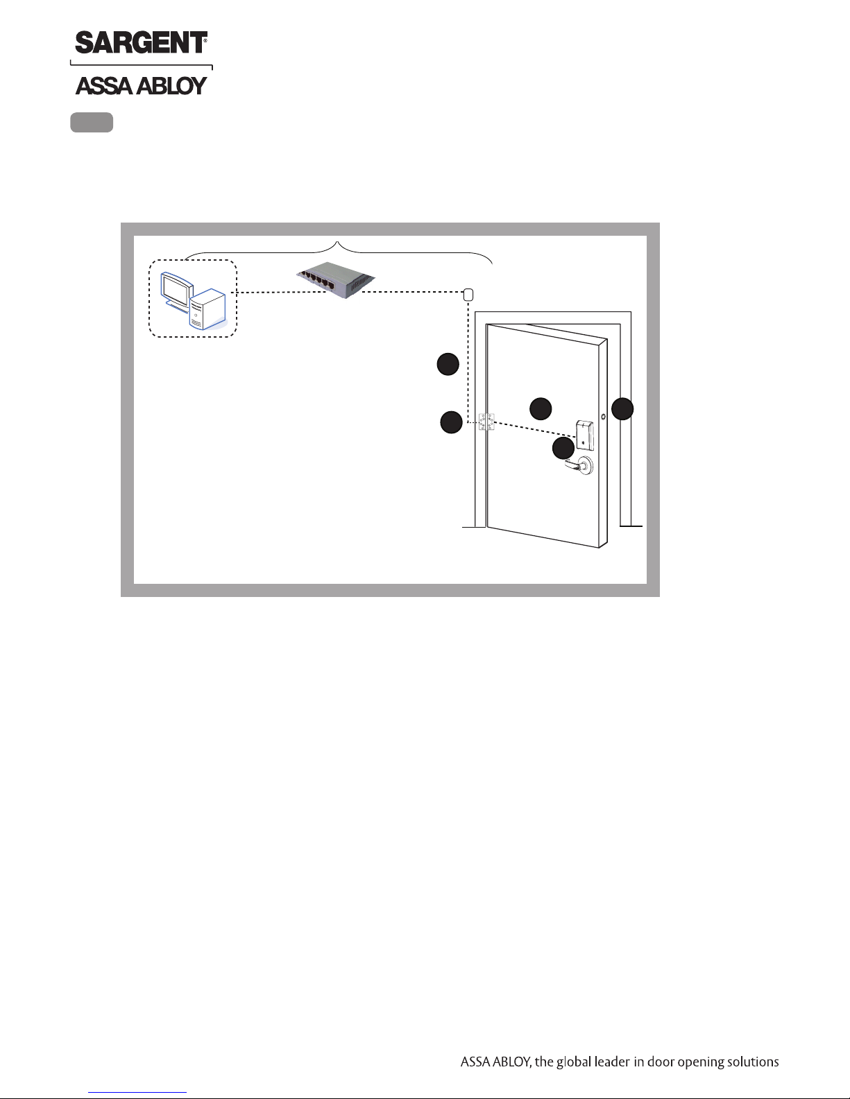
6
Installation Wiring
Overview
SARGENT IN220 PoE Typical Application
Network Switch (802.3af)
IN220 Cylindrical Lock
Network Cable
Surface Mount RJ45
LMT: Lock Management Tool
A. PoE frame harness assembly
B. PoE data hinge from McKinney
(patent pending)
C. PoE door harness* from McKinney
D. IN220 PoE Lock
E. DPS: Door Position Switch
(Needed on Cylindrical and Exits only)
* Door width determines length
A
B
C
D
E
Copyright © 2016, Sargent Manufacturing Company, an ASSA ABLOY Group company. All rights reserved.
Reproductions in whole or in part without express written permission of Sargent Manufacturing Company is prohibited.
04/30/16
7 1-800-810-WIRE • www.sargentlock.com • A8203A
Page 8
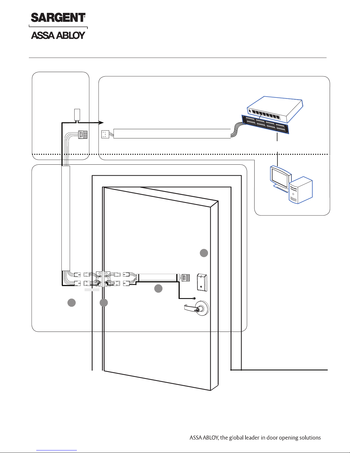
Installation Wiring (Continued)
IN220 Cylindrical Lock
Supplied by CI
Crimp Connector
Ceiling
24AWG
Stranded
Drain
Wire for
Earth
Ground in
15' Frame
Harness
Frame-Side
Harness
Assembly
(15' length)
Cable
drain wire
concealed in
shrink tubing
B-Splice
RJ45-M
24 AWG , 100ohm
Cable: Cat 5e or higher
Molex-M
Molex-F
A
Certified Integrator (CI) supplies and terminates
the B-Splice connector and the
male RJ45 connector from harness to
end user provided facility cable
To building or electrical ground
RJ45-F Jack
Cable: Cat 5e or higher
24 AWG
Cable: Cat 5e,
26 AWG stranded,
100ohm
Molex-F
Molex-M
C
B
Ring Terminal
Secured to Lock
Mounting Plate
Ground
RJ45-M
Patch Cable
Patch Panel to
PoE Switch
D
PoE
Lock
Supplied by End User
PoE Switch
PoE Switch is
Terminated to
Earth Ground
Patch Panel
Approved Software
Notes:
• Connectors go on only one
way. They cannot be placed
in an incorrect position.
• Do not force and do not
offset connectors.
• Be sure they are completely
seated (flush).
• PoE power source cannot
be connected to a receptacle controlled by a switch
Copyright © 2016, Sargent Manufacturing Company, an ASSA ABLOY Group company. All rights reserved.
Reproductions in whole or in part without express written permission of Sargent Manufacturing Company is prohibited.
04/30/16
8 1-800-810-WIRE • www.sargentlock.com • A8203A
Wiring to TIA/EIA 568-B Standard
Page 9

Installation Wiring (Continued)
A
Frame Harness Installation
IN220 Cylindrical Lock
Supplied by CI
Crimp Connector
Ceiling
24AWG
Stranded
Drain
Wire for
Earth
Ground in
15' Frame
Harness
Frame-Side
Harness
Assembly
(15' length)
Cable
drain wire
concealed in
shrink tubing
B-Splice
RJ45-M
Cable: CAT 5e or higher
Molex-M
Components and wire harness supplied by McKinney. Suggested installation:
Cut end / ceiling-side PoE harness:
TIA/EIA 568-B Standard Wiring
5
4
24 AWG 100ohm
Hinge side of PoE (Frame) harness:
1. Feed cut end of harness into hole on hinge-side through single access hole.
2. Push one connector back through the hole and feed into the other access hole.
6
3
2
1
7
8
1
pin
8
pin
8
1
Do not confuse pair numbers with pin numbers. A pair number is
used for reference only (eg: 10BaseT Ethernet uses pairs 2 & 3). The
pin numbers indicate actual physical locations on the plug and jack.
Each of the hinge-side harness connectors should end up threaded through
a different access hole and matched to the same size pin connector from
the door harness:
• 4-pin male molex connector
• 6-pin male molex connector with ground wire
PIN Wire Pair
1 White/Orange 2
2 Orange 2
3 White/Green 3
4 Blue 1
5 White/Blue 1
6 Green 3
7 White/Brown 4
8 Brown 4
Number
PoE Data Hinge
Frame
4-pin M
6-pin M
4-pin F
6-pin F
Copyright © 2016, Sargent Manufacturing Company, an ASSA ABLOY Group company. All rights reserved.
Reproductions in whole or in part without express written permission of Sargent Manufacturing Company is prohibited.
04/30/16
B
9 1-800-810-WIRE • www.sargentlock.com • A8203A
PoE Hinge
4-pin F
Hinge-side harness connectors:
• 4-pin female molex connector
• 6-pin female molex connector with ground wire
Lock-side harness connectors:
• 4-pin female molex connector
• 6-pin female molex connector with ground wire
6-pin F
Page 10

C
PoE Door Harness
Order of installation may vary. Refer to appropriate sections for instructions.
Hinge-side harness connectors:
• 4-pin male Molex connector
• 6-pin male Molex connector with ground wire
Lock-side harness connectors:
• Ring terminal
• Male RJ45 connector (crimped after cable is fed through door)
Notes:
• Connectors go on only one way. They cannot be plugged to incorrect position.
• Do not force and do not offset connectors.
• Be sure they are completely seated (flush).
IN220 Cylindrical Lock
4-pin F
6-pin F 6-pin F
D
PoE Lock
PoE Hinge
4-pin F
4-pin M
6-pin M
Drain Wire
PoE Door Harness
Cable: CAT 5e,
26 AWG stranded,
100ohm
Order of installation may vary. Refer to appropriate sections for instructions.
1. Prop door open.
2. Using the ring terminal, carefully route the assembly through the door
channel to the lock.
IN220 PoE Lock
RJ45-M
Copyright © 2016, Sargent Manufacturing Company, an ASSA ABLOY Group company. All rights reserved.
Reproductions in whole or in part without express written permission of Sargent Manufacturing Company is prohibited.
04/30/16
10 1-800-810-WIRE • www.sargentlock.com • A8203A
Page 11

7
Lock Installation
1 Prepare Door
A. Verify Hand and Bevel of Door
Stand on outside of locked door when determining door hand.
IN220 Cylindrical Lock
LH
Left Hand
Hinges Left
Open Inward
B. Verify Product Label
C. Prepare Door
Prior to installation, all holes must be free of burrs, debris and sharp edges.
Prepare door according to appropriate template (see website www.intelligentopenings.com).
• Field Template: A8149 (ships with product)
• Door Manufacturer’s Template: 4712
Cable Hole
Raceway for Lock
Body Harness
Through-bolt Hole
LHRB
Left Hand
Reverse Bevel
Hinges Left
Open Outward
Fig. 1A
Through-bolt
Holes
External
DPS
holes
Lever Handle
Hole
Cylindrical
Pocket and
Latch Holes
RH
Right Hand
Hinges Right
Open Inward
Inside of DoorOutside of Door
RHRB
Right Hand
Reverse Bevel
Hinges Right
Open Outward
Cable Hole
Raceway for
Cat 5e (PoE)
Raceway for Lock
Body Harness
Through-bolt
Hole
Copyright © 2016, Sargent Manufacturing Company, an ASSA ABLOY Group company. All rights reserved.
Reproductions in whole or in part without express written permission of Sargent Manufacturing Company is prohibited.
04/30/16
11 1-800-810-WIRE • www.sargentlock.com • A8203A
Pre-drilled
Tap Holes
Fig. 1B Wood Door Preparation
Page 12

IN220 Cylindrical Lock
2 Install Strike
Install strike in the door frame (Fig. 2).
(2) #8-32 x 3/4"
3 Install Latchbolt
1. Install latch with beveled bolt facing the strike.
2. Attach with two screws but DO NOT tighten completely at this time.
See step 8 - Secure Lock to Door.
IMPORTANT: Latch bevel must match door bevel and
deadlocking latch must stop on strike when door is closed.
Centerline of Latch
Latch Screws
Front and Strike
Fig. 2
Inside of Door
PoE Harness
(Cat 5e and
ground)
Strike
Fig. 3B
Deadlocking Latch
IMPORTANT:
• Door must remain open during installation.
Use door stop.
Fig. 3A
4 Install Door Position Switch (DPS)
1. Push wires through raceway toward lock prep.
2. Push DPS firmly into place by hand.
Note: DO NOT TAP SWITCH WITH ANY TOOL.
3. Install magnet into door frame. Push firmly into place by hand.
See A7983.
4. To connect DPS to lock controller per diagram, refer to the wiring in
Step #14 section 3.
(Door Position Switch)
DPS
CAUTION: if DPS is not installed or is installed
improperly, door status monitoring features will
Copyright © 2016, Sargent Manufacturing Company, an ASSA ABLOY Group company. All rights reserved.
Reproductions in whole or in part without express written permission of Sargent Manufacturing Company is prohibited.
not function.
Fig. 4
Inside of Door
04/30/16
12 1-800-810-WIRE • www.sargentlock.com • A8203A
Page 13

5
Lock Adjustments
A. Lock Preset:
• Lock body holes: 12 and 6 o’clock (Fig. 5).
The lock is shipped “preset” and does not require adjustment for 1-3/4” thick doors.
Outside of Door
IN220 Cylindrical Lock
Fig. 5
Door thickness:
1-3/4” thick
NOTE: Adjusting for a thicker door requires removal of the outside lever, scalp and
spacer bushing; see following sections.
If preset lock does not require adjustment, proceed to Step 7 - Install Lock
Copyright © 2016, Sargent Manufacturing Company, an ASSA ABLOY Group company. All rights reserved.
Reproductions in whole or in part without express written permission of Sargent Manufacturing Company is prohibited.
04/30/16
13 1-800-810-WIRE • www.sargentlock.com • A8203A
Page 14

6 Through-Bolt and Door Thickness Adjustment (If Required)
A. Remove Outside Lever
1. Insert key, rotate 45° clockwise and hold.
2. Depress lever retainer with push pin tool (provided).
3. Pull lever outward.
Outside of Door
IN220 Cylindrical Lock
B. How To Change Cylinder (If Necessary)
1. With outside lever in hand, use standard pliers
to pull out cylinder retainer.
2. Remove key and cylinder from lever.
3. Insert new cylinder.
4. Secure by pressing cylinder retainer flush with the lever.
Washers required for
30- prefix (10 Line Lever)
to accept Schlage cylinder
(no cylinder provided)
Cylinder
Spacer
Cylinder
Retainer
Fig. 6B
Fig. 6A
Key
Outside
Lever
Cylinder
Push Pin Tool
Copyright © 2016, Sargent Manufacturing Company, an ASSA ABLOY Group company. All rights reserved.
Reproductions in whole or in part without express written permission of Sargent Manufacturing Company is prohibited.
04/30/16
14 1-800-810-WIRE • www.sargentlock.com • A8203A
Page 15

C. Through-Bolt and Door Thickness Adjustment
1. (If necessary) remove outside lever, scalp and spacer
bushing (Fig. 6C).
IN220 Cylindrical Lock
Spacer Bushing
Scalp
Outside Lever
2. Rotate mounting plate to either align with through-bolt holes in
door, or adjust for proper door thickness (Fig. 6D).
Refer to markings on through-bolt post (Fig. 6C Detail).
1-3/4” Thick Doors
2” Thick Doors
Fig. 6C Detail
Fig. 6C
3. Re-install spacer bushing to align with back
of lever, scalp, and lever (Fig. 6D).
Copyright © 2016, Sargent Manufacturing Company, an ASSA ABLOY Group company. All rights reserved.
Reproductions in whole or in part without express written permission of Sargent Manufacturing Company is prohibited.
04/30/16
15 1-800-810-WIRE • www.sargentlock.com • A8203A
Fig. 6D
Page 16

7 Install Lock
1. From outside of door, feed lock body harness into the lock body hole (Fig. 7A).
For metal door: Feed harness through inside of door (not shown).
2. Continue to feed harness into raceway (towards top of door), exiting raceway
hole on inside of door (Fig. 7B).
3. Slide lock body into cross-bore hole from outside of door.
4. Lock body must engage both the latch unit prongs and tail piece (Fig. 7C).
IMPORTANT:
• Door must remain open during installation (use door stop).
• Lock body must be centered in the door.
• Tuck excess wires into raceway to avoid pinching wires.
NOTE: Cable lengths exaggerated for illustrative purposes.
IN220 Cylindrical Lock
Fig. 7B Detail
Inside of Door
PoE
Harness
(Cat 5e)
Outside of Door
Ground Ring
Terminals
Fig. 7A
Copyright © 2016, Sargent Manufacturing Company, an ASSA ABLOY Group company. All rights reserved.
Reproductions in whole or in part without express written permission of Sargent Manufacturing Company is prohibited.
04/30/16
16 1-800-810-WIRE • www.sargentlock.com • A8203A
Fig. 7C Detail
Page 17

IN220 Cylindrical Lock
8 Secure Lock To Door
1. Feed wire and connector:
• For wood door, feed connectors and wires through the door
and up the wire run channel (Fig. 8A).
• For metal door (not shown), feed connectors and wires into
the lockbody hole and out the controller hole.
2. Position ground lug between (top) #10-32x1-1/4” through-bolt
and rose assembly (Fig. 8A).
NOTE: Proper placement of ground wire (Fig. 8A, B) will prevent
pinching/damage to the ground wire.
3. Secure rose assembly with (2) #10-32x1-1/4” through-bolts.
4. Secure latch by fully tightening (2) #6 x 3/4” self-tapping screws
(refer to previous section 3 - Install Latchbolt).
NOTE: Cable lengths exaggerated for illustrative purposes.
Inside of
Door
Ground
Wire
9 Assemble Inside Trim
1. Verify spacer bushing is inserted horizontally and
aligned with lever (Fig. 9).
2. Place rose over shaft of lock body against the
surface of the door; hand-tighten, turning clockwise.
3. Attach lever. Push until engaged.
Fig. 8A
Fig. 8B Detail
Inside of Door
Rose
Fig. 9
1-800-810-WIRE • www.sargentlock.com • A8203A 17
Inside lever
Copyright © 2016, Sargent Manufacturing Company, an ASSA ABLOY Group company. All rights reserved.
Reproductions in whole or in part without express written permission of Sargent Manufacturing Company is prohibited.
04/30/16
Page 18

IN220 Cylindrical Lock
10 Outside Reader and Inside Mounting Plate Installation
1. Orient the reader so the LED lens is at the top.
2. Feed the reader harness through the door (from outside to inside).
3. Install the reader to the outside of door by aligning the mounting posts with the door preparation holes.
Hold the reader flush against door while ensuring proper alignment.
Outside of Door
LED
Reader Assembly
with Harness
Copyright © 2016, Sargent Manufacturing Company, an ASSA ABLOY Group company. All rights reserved.
Reproductions in whole or in part without express written permission of Sargent Manufacturing Company is prohibited.
04/30/16
18 1-800-810-WIRE • www.sargentlock.com • A8203A
Fig. 10A
Page 19

IN220 Cylindrical Lock
10 Outside Reader Installation (Continued)
4. Next feed the cables/connectors through the inside mounting assembly (and gasket if required*).
5. Secure the mounting assembly while ensuring proper alignment of outside reader and partially tighten
the (2) through-bolts on the inside of the door to secure the reader (Fig. 10B).
NOTE: Cable lengths exaggerated for illustrative purposes.
Inside of Door
Gasket*
Mounting Plate
Fig. 10B
6. Secure both ground lugs with #6-32 machine screw (Fig.10C).
Through -
bolts
Fig. 10C
*Gasket is required for outdoor installations.
If installing with gasket; separate gasket from mounting plate to feed cables/connectors
through holes as indicated (Fig. 10B).
Once cables/connectors are fed through, reattach gasket to mounting plate.
1-800-810-WIRE • www.sargentlock.com • A8203A 19
Copyright © 2016, Sargent Manufacturing Company, an ASSA ABLOY Group company. All rights reserved.
Reproductions in whole or in part without express written permission of Sargent Manufacturing Company is prohibited.
04/30/16
Page 20

11 Installation of Connectors
CAUTION - Do not touch or allow debris to enter connector contacts.
Secure the following connectors to their respective terminals (Fig. 11A, B):
A. Secure the 4-pin DPS connector.
B. Secure the 10-pin lock body assembly connector.
IMPORTANT: Do not run wires through bottom hole in plate (Fig. 11A, B)
- it will damage wires and the controller connector. Route wires around
flange, do not route wires through the flange hole (Fig. 11B).
Secure Mounting Plate
1. Tuck excess cable into wire hole on inside of door.
2. Secure the mounting assembly while ensuring proper
alignment of outside reader and fully tighten the (2) through bolts on the inside of the door to secure the reader and plate
to the door.
Ground
Lugs
IN220 Cylindrical Lock
DPS (4-pin)
A
B
Reader
(24-pin)
Fig. 11A
C
Lock
Body
(10-pin)
C. Secure the 24-pin card reader connector (Fig. 11B).
D. Crimp* RJ45 to Cat 5e cable from hinge (Fig. 11C).
*For more detail, refer to section (5) ‘Installation Wiring’,
“A - Frame Harness Installation”.
Board-to-Board
TIA/EIA 568-B Standard Wiring
PIN Wire Pair
5
6
4
7
3
2
1
8
1
pin
8
pin
8
1
1 White/Orange 2
2 Orange 2
3 White/Green 3
4 Blue 1
5 White/Blue 1
6 Green 3
7 White/Brown 4
8 Brown 4
Number
Do not confuse pair numbers with pin numbers. A pair number is
used for reference only (eg: 10BaseT Ethernet uses pairs 2 & 3). The
pin numbers indicate actual physical locations on the plug and jack.
Connector
Crimp* to RJ45-M
Connector
RJ45-M
Fig. 11B
Cat 5e cable
from hinge
Fig. 11C
Copyright © 2016, Sargent Manufacturing Company, an ASSA ABLOY Group company. All rights reserved.
Reproductions in whole or in part without express written permission of Sargent Manufacturing Company is prohibited.
04/30/16
20 1-800-810-WIRE • www.sargentlock.com • A8203A
Page 21

IN220 Cylindrical Lock
12
Installation of Inside Module Component Assembly
1. Insert top tabs of controller into slots on mounting plate (Fig. 12A, B).
2. Ensure proper alignment of board-to-board connectors while pivoting bottom
of controller toward door until tab on bottom snaps securely into place on
mounting plate.
CAUTION: To avoid possible damage to board-to-board connectors,
care should be taken when securing controller to mounting
plate. If there is resistance when securing, detach controller
to determine cause before re-attaching controller.
3. Connect RJ45 male connector to female RJ45 on controller board (Fig. 12B).
Fig. 12A
Fig. 12B
4. Remove pull tab from its position
beneath the coin cell by pulling
on tab in direction of arrows
printed on tab (Fig. 11B).
1-800-810-WIRE • www.sargentlock.com • A8203A 21
Copyright © 2016, Sargent Manufacturing Company, an ASSA ABLOY Group company. All rights reserved.
Reproductions in whole or in part without express written permission of Sargent Manufacturing Company is prohibited.
04/30/16
Page 22

13
Inside Cover Installation
1. Assemble cover by hooking top edge on inside
mounting plate.
2. Carefully press bottom of cover toward door without
pinching any wires.
3. Secure cover utilizing security allen wrench.
IN220 Cylindrical Lock
Fig. 13
Inside
Cover
Security Allen
Screw
Copyright © 2016, Sargent Manufacturing Company, an ASSA ABLOY Group company. All rights reserved.
Reproductions in whole or in part without express written permission of Sargent Manufacturing Company is prohibited.
04/30/16
22 1-800-810-WIRE • www.sargentlock.com • A8203A
Page 23

IN220 Cylindrical Lock
8
Operational Check
1. Insert key into cylinder and rotate (Fig. 14A).
There should be no friction against lock case, wire
harness or any other obstructions.
2. Check that the key retracts the latch.
3. The key should rotate freely.
4. Try the inside lever; ensure it retracts latch.
5. Use a valid credential* set up with the Lock
Configuration Tool to unlock outside lever and
retract latch.
Refer to Network and Lock Configuration
Tool user manual (WFMN1) for information on
how to configure and program locks.
Fig. 14A
Note: The credential should approach the inscription
on the reader as indicated (Fig. 14B) to ensure
the credential is read properly.
Do not wave credential.
Fig. 14B
1-800-810-WIRE • www.sargentlock.com • A8203A 23
Copyright © 2016, Sargent Manufacturing Company, an ASSA ABLOY Group company. All rights reserved.
Reproductions in whole or in part without express written permission of Sargent Manufacturing Company is prohibited.
04/30/16
Page 24

SARGENT Manufacturing
100 Sargent Drive
New Haven, CT 06511 USA
800-810-WIRE (9473) • www.sargentlock.com
HID and iCLASS are registered trademarks of HID Global Corporation.
Founded in the early 1800s, SARGENT® is a market leader in locksets, cylinders, door closers, exit devices,
electro-mechanical products and access control systems for new construction, renovation, and replacement applications.
The company’s customer base includes commercial construction, institutional, and industrial markets.
Copyright © 2016, Sargent Manufacturing Company, an ASSA ABLOY Group company. All rights reserved.
Reproduction in whole or in part without the express written permission of Sargent Manufacturing Company is prohibited.
ASSA ABLOY is the global leader in door opening solutions, dedicated to
satisfying end-user needs for security, safety and convenience.
A8203A - 04/16
 Loading...