

Page 1
INSTALLATION INSTRUCTIONS for
™
RDL Lever Lock with Simplí
Roseless Trim (Patents Pending)
FOR INSTALLATION ASSISTANCE CALL SARGENT AT 1-800-727-5477 / www.sargentlock.com
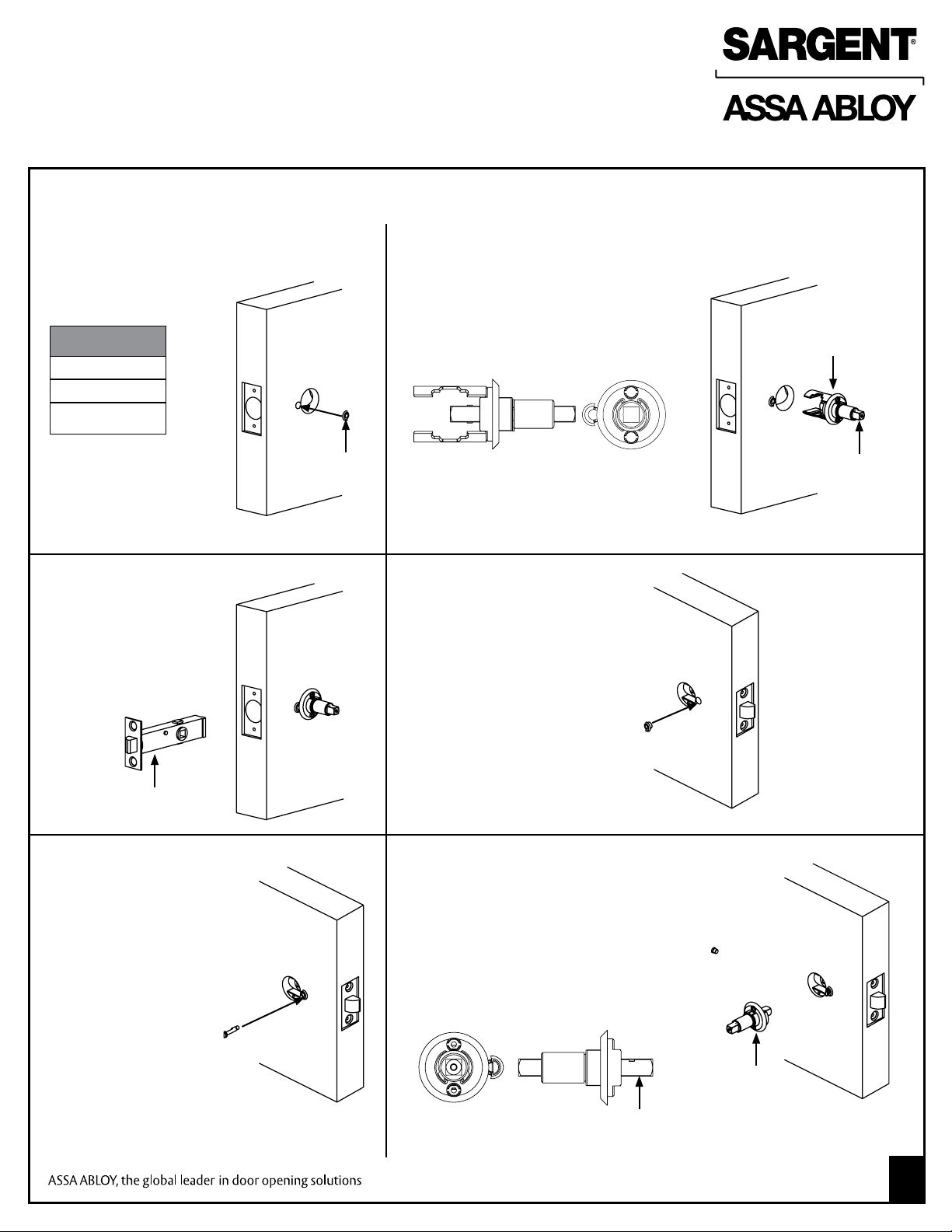
Installing an RDL Lock
STEP 1
Insert outside bushing as shown
(65 function only)
Tools Required:
Phillips Screwdriver
T20 Torx Wrench
Lever Base Tool
(Provided)
STEP 3
Insert latch assembly
• Position the threaded
hole on the latch
assembly towards the
inside of the door
(65 function only)
Outside
of Door
Outside
Bushing
STEP 2
Insert outside mounting plate assembly
• Ensure that the spindle is pre-assembled
to the mounting plate assembly
• Orient the bushing to avoid interference
as shown (65 function only)
STEP 4
Insert inside bushing as shown
(65 function only)
Outside Mounting
Plate Assembly
Spindle of
Outside
Mounting
Plate
Assembly
Latch
Assembly
STEP 5
Assemble privacy button
to latch assembly
(65 function only)
• Thread the privacy
button into the threaded
hole of the latch assembly
through the inside bushing
Note: Loosening the pre assembled #6-32 screws on
the outside mounting plate may improve alignment for
thicker doors.
STEP 6
• Verify the spindle is assembled to the
mounting plate assembly
• Position and secure inside mounting
plate assembly with two #6-32 screws
provided (not shown)
• Orient the bushing and privacy pin
as shown to avoid interference
(65 function only)
Spindle
Copyright © 2010, Sargent Manufacturing Company, an ASSA ABLOY Group company.
All rights reserved. Reproduction in whole or in part without the express written permission
of Sargent Manufacturing Company is prohibited.
Mounting
Plate
Assembly
A8046:B 9-01-10
1
Page 2
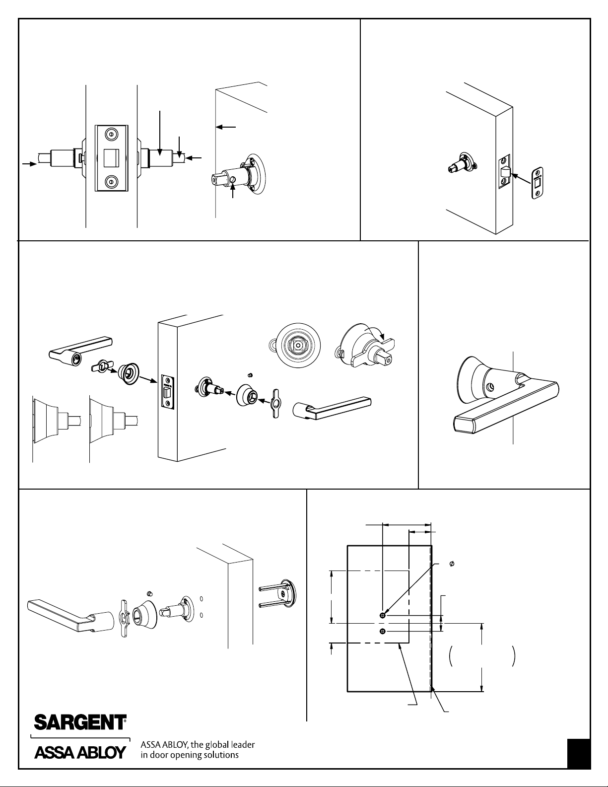
STEP 7
2-3/4" Standard
2-3/8" (20-)
BACKSET
2X
.250
± .016
THRU
.900
± .016
38"
FROM
FINISHED FLOOR
SUGGESTED HEIGHT
1.250
MIN
6"
MIN
3"
MIN
OUTSIDE
OF DOOR
SUITABLE REINFORCEMENT IN
AREA SHOWN TO PREVENT
BOWING OF DOOR SURFACES
C
L
OF
BEVEL
Rotate and verify the set screw hole in both mounting plate assemblies
face the hinge and push both spindles into the latch assembly hubs.
Mounting Plate
Assembly
STEP 8
Position the outside front onto the latch
assembly and secure with provided screws
spindle
Front Edge
of Door
Set screw hole on
lever bushing must
face the hinge
STEP 9
Assemble the inside and outside collars by threading to the mounting plate with
provided tool
• Orient the bushing to collar as shown (65 function only)
STEP 10
Assemble the inside and outside
levers with provided set screw
(not shown)
• Test assembly
• Install Strike
X
Note: Collars must lie ush against the door
Dummy Trim Assembly Shown
Use assembly steps 2, 6, 9 & 10 for
dummy trim installation
Edge of Door
Template for RDLU93 & RDLU94
Notes: For use with
RDLU93 & RDLU94
functions only.
Copyright © 2010, Sargent Manufacturing Company, an ASSA ABLOY Group company.
All rights reserved. Reproduction in whole or in part without the express written permission
of Sargent Manufacturing Company is prohibited.
A8046:B 9-01-10
2
 Loading...