

Page 1
A7455B
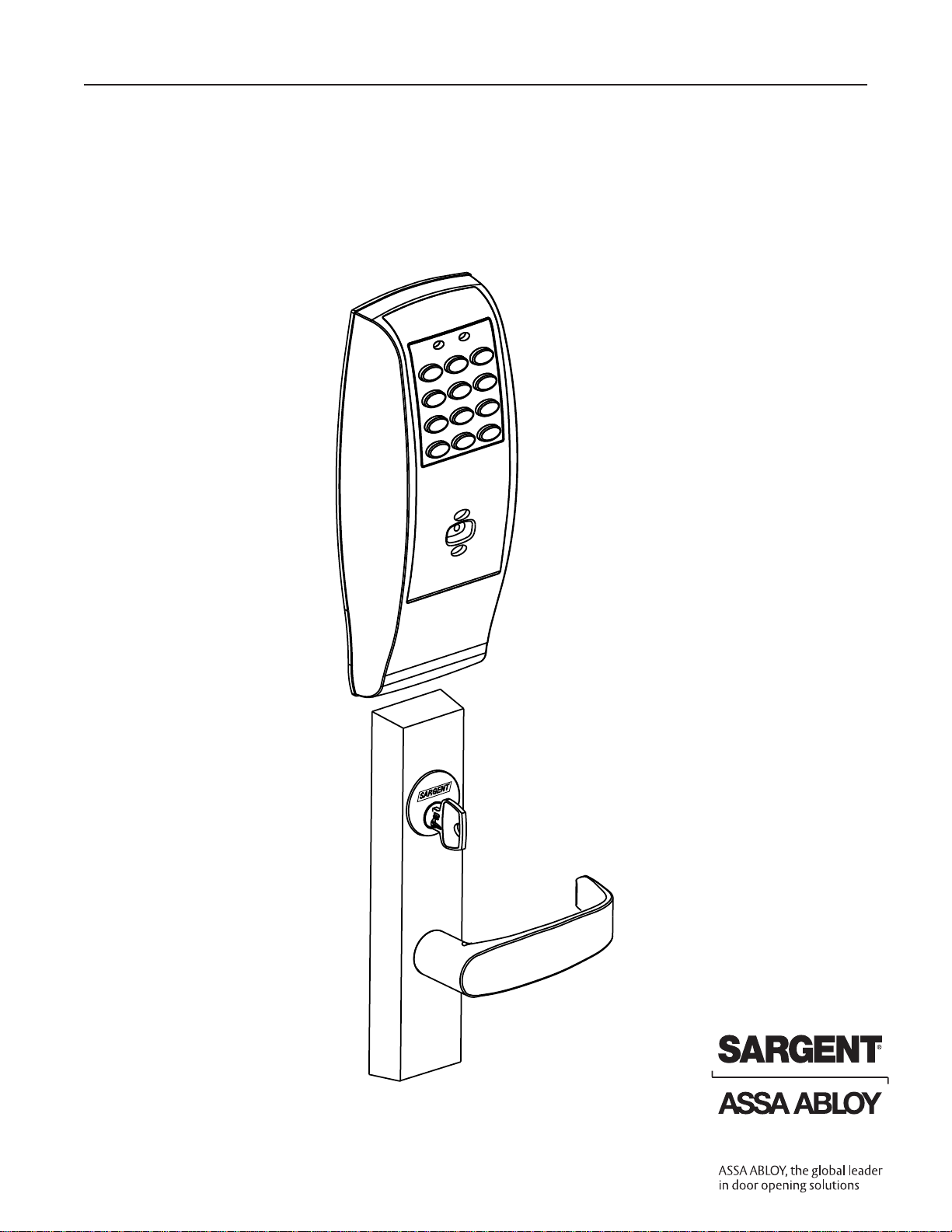
Installation Instructions For
Profile Series Exit Device
Copyright © 2003, 2008, Sargent Manufacturing Company, an ASSA ABLOY Group company.
All rights reserved. Reproduction in whole or in part without the express written permission of
Sargent Manufacturing Company is prohibited.
FOR ASSISTANCE, CONTACT SARGENT AT 800-727-5477 or www.sargentlock.com
Page 2
800-810-WIRE (9473) • www.sargentlock.com • A7455B
Profile Series Exit Device
Copyright © 2003, 2008, Sargent Manufacturing Company, an ASSA ABLOY Group company. All rights reserved.
Reproduction in whole or in part without the express written permission of Sargent Manufacturing Company is prohibited.
Table of Contents
Page
Warning and Items Supplied . . . . . . . . . . . . . . . . . . . 1
Parts Breakdown . . . . . . . . . . . . . . . . . . . . . . . . . . 2-3
Rim Installation Instructions . . . . . . . . . . . . . . . . . 4-7
Mortise Installation Instructions . . . . . . . . . . . . . 8-11
Operational Check . . . . . . . . . . . . . . . . . . . . . . . . . . 12
Basic Programming Instructions . . . . . . . . . . . . 12-21
Chain Programming . . . . . . . . . . . . . . . . . . . . . . . . . 22
Transaction Log . . . . . . . . . . . . . . . . . . . . . . . . . . . . 23
Supplemental - Individual Door Log Sheet . . . . . . . 24
1
2
3
4
5
6
7
8
9
Page 3
1
800-810-WIRE (9473) • www.sargentlock.com • A7455B
Profile Series Exit Device
Copyright © 2003, 2008, Sargent Manufacturing Company, an ASSA ABLOY Group company. All rights reserved.
Reproduction in whole or in part without the express written permission of Sargent Manufacturing Company is prohibited.
This device complies with Part 15 of the FCC Rules. Operation is subject to the following two
conditions: (1) this device may not cause harmful interference, and (2) this device must accept
any interference received, including interference that may cause undesired operation.
Note: This equipment has been tested and found to comply with the limits for a Class B digital
device, pursuant to Part 15 of the FCC Rules. These limits are designed to provide reasonable
protection against harmful interference in a residential installation. This equipment generates,
uses and can radiate radio frequency energy and if not installed and used in accordance with the
instructions, may cause harmful interference to radio communications. However, there is no
guarantee that the interference will not occur in a particular installation. If this equipment does
cause harmful interference to radio or television reception, which can be determined by turning
the equipment off and on, the user is encouraged to try to correct the interference by one or more
of the following measures:
• Reorient or relocate the receiving antenna
• Increase the separation between the equipment and receiver
• Connect the equipment into an outlet on a circuit different from that to which the receiver
is connected
• Consult the dealer or an experienced TV technician for help
This Class B digital apparatus complies with Canadian ICES-003.
Cet appareil numÈrique de la classe B est conforme ‡ la norme NMB-003 du Canada.
Warning
1
Warning: Changes or modifications to this
unit not expressly approved by the party
responsible for compliance could void the
user's authority to operate the equipment.
Warning
!
To comply with “Fire Listed” doors, the batteries must be replaced with alkaline batteries only.
Items Supplied with Exit Device
Items included in your 8877 and 8977 Series Exit Device
carton:
• Outside Escutcheon with Keypad
• Outside motorized Trim Assembly
• Exit Device
• Mortise cylinder for 8977
• Rim cylinder for 8877
• Inside Escutcheon with Circuit Board and Battery Pack
• 6 “A” alkaline batteries
• Screw Pack
Items included in your 8878 and 8978 Series Exit Device
Carton:
• Outside Escutcheon with Keypad
• Outside Motorized Trim Assembly
• Exit Device
• Inside Escutcheon with Circuit Board and Battery Pack
• 6 “A” alkaline batteries
• Screw Pack
Page 4
2
800-810-WIRE (9473) • www.sargentlock.com • A7455B
Profile Series Exit Device
Copyright © 2003, 2008, Sargent Manufacturing Company, an ASSA ABLOY Group company. All rights reserved.
Reproduction in whole or in part without the express written permission of Sargent Manufacturing Company is prohibited.
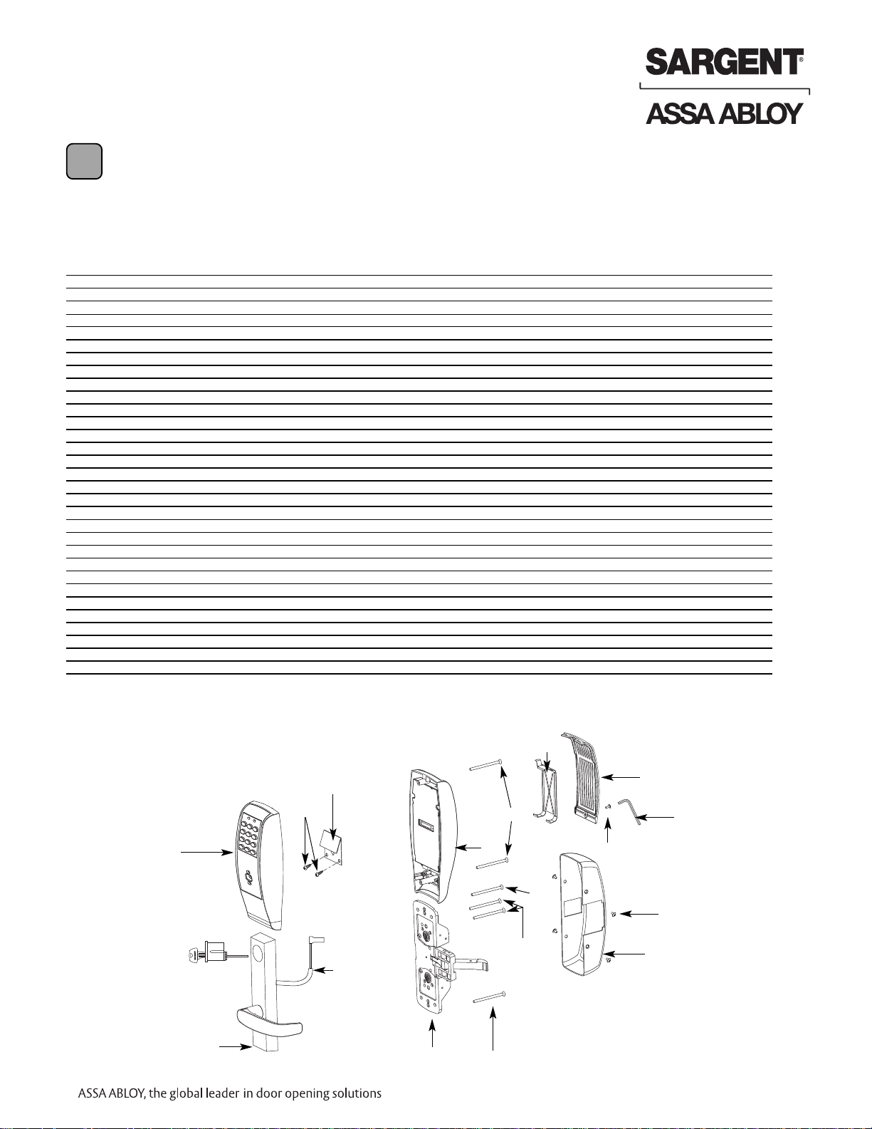
Parts Breakdown
2
Door
QER .ON NOITPIRCSED REBMUNTRAP METI ’D
1)AP( ylbmessA noehctucsE edistuO5742-251
1 )KP,UL ,KL( ylbmessA noehctucsE edistuO4742-251
1)KP ,UL ,KL( ylbmessA ytimixorP dna daP yeK2342-25
1)AP( ylbmessA ytimixorP1342-25
1ylnO gnisuoH noehctucsE edistuO7931-86
1ylnO paC dnE noehctucsE edistuO6710-25
2 52-2460 Inside Escutcheon Assembly with 100 User Controller (LK) 1
2 52-2461 Inside Escutcheon Assembly with 500 User Controller (LU) 1
2 52-2462 Inside Escutcheon Assembly with Prox / Key Pad Controller (PA/PK) 1
1ylnO gnisuoH noehctucsE edisnI6931-86
1ylnO paC dnE noehctucsE edisnI5710-25
1ylbmessA rellortnoC )KL(1442-25
1ylbmessA rellortnoC )UL(8442-25
1ylbmessA rellortnoC )AP/KP(5542-25
01-0803 Battery Alkaline (“AA” 6)lleC
1 revoC yrettaB0710-253
1wercS ytiruceS2121-104
1looT ytiruceS7920-105
1etalP potS eriF3300-256
7 01-1500 Fire Stop Screws #8 x 1/2” Type “AB” Phillips Pan Head Self Tap 2
1repeeK yrettaB3520-259
1)51 ,7 ,6 ,5 srebmun meti sedulcnI( kcaP wercS5242-2501
1mirT reveLTE dezirotoMyrotcaF tlusnoC11
1ylbmessA ssenraH dna rotoM6552-2521
2stloB-urhTTE1544-1031
2 stloB-urhT noehctucsE5860-7751
1)-21 dna dradnatS( BRHL ylbmessA esaC retneC2712-8661
1)-21 dna dradnatS( BRHR ylbmessA esaC retneC3712-8661
1BRHL kcoL esitroM1042-9971
1BRHR kcoL esitroM2042-9971
1revoC sissahC7040-8681
4swercS revoC sissahC2500-7991
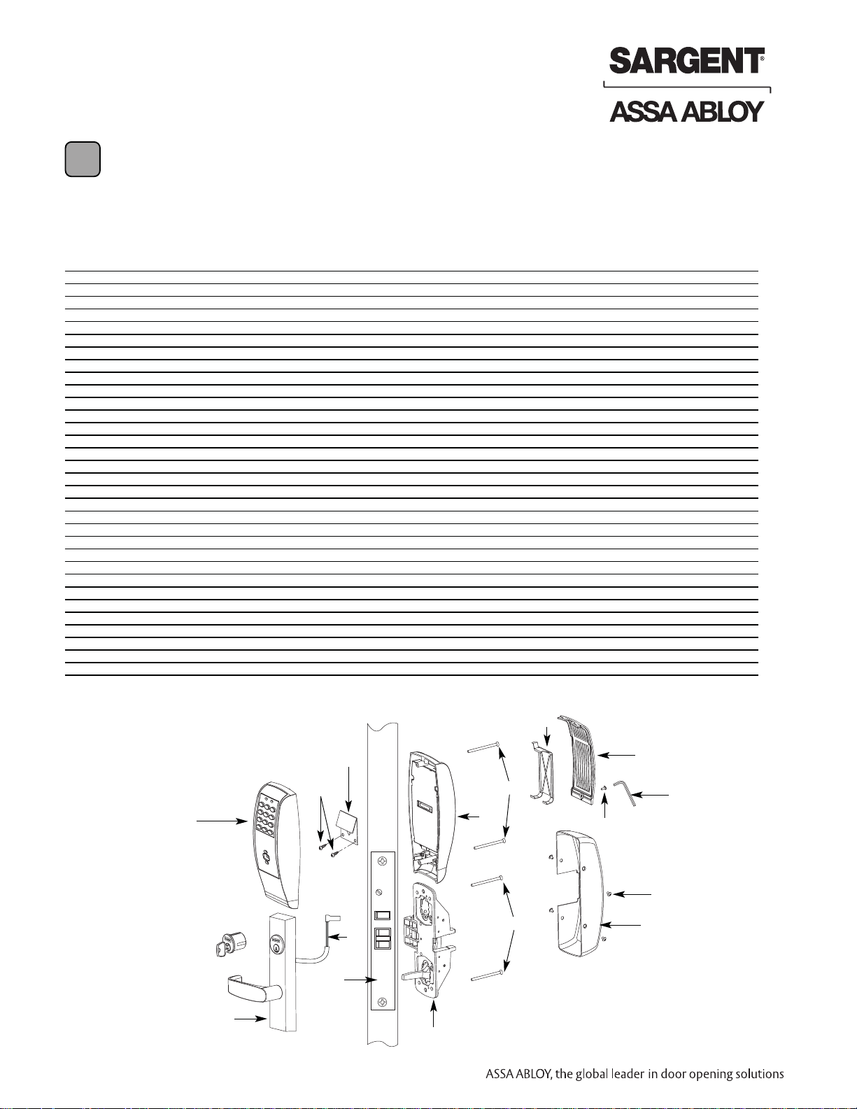
8977/8978 x ET x Lever Design
Profile Series Mortise Exit Device
1
2
11
17
12
7
6
16
3
5
4
18
19 (X4)
9
15
13
Page 5
3
800-810-WIRE (9473) • www.sargentlock.com • A7455B
Profile Series Exit Device
Copyright © 2003, 2008, Sargent Manufacturing Company, an ASSA ABLOY Group company. All rights reserved.
Reproduction in whole or in part without the express written permission of Sargent Manufacturing Company is prohibited.
Parts Breakdown (Continued)
2
QER .ON NOITPIRCSED REBMUNTRAP METI ’D
1)AP( ylbmessA noehctucsE edistuO5742-251
1)KP,UL ,KL( ylbmessA noehctucsE edistuO4742-251
1)KP ,UL ,KL( ylbmessA ytimixorP dna daP yeK2342-25
1)AP( ylbmessA ytimixorP1342-25
1ylnO gnisuoH noehctucsE edistuO7931-86
1paC dnE noehctucsE edistuO6710-25
2 52-2460 Inside Escutcheon Assembly with 100 User Controller (LK) 1
2 52-2461 Inside Escutcheon Assembly with 500 User Controller (LU) 1
2 52-2462 Inside Escutcheon Assembly with Prox / Key Pad Controller (PA/PK) 1
1ylnO gnisuoH noehctucsE edisnI6931-86
1ylnO paC dnE noehctucsE edisnI5710-25
1ylbmessA rellortnoC )KL(1442-25
1ylbmessA rellortnoC )UL(8442-25
1ylbmessA rellortnoC )KP/AP(5542-25
1revoC yrettaB0710-253
1wercS ytiruceS2121-104
1looT ytiruceS7920-105
1etalP potS eriF3300-256
7 01-1500 Fire Stop Screws #8 x 1/2” Type “AB” Phillips Pan Head Self Tap 2
01-0803 Battery Alkaline (“AA” 6 )lleC
1repeeK yrettaB3520-259
1)51 ,7 ,6 ,5 srebmun meti sedulcnI( kcaP wercS5242-2501
1mirT reveLTE dezirotoMyrotcaF tlusnoC11
1ylbmessA ssenraH dna rotoM6552-2521
2stloB-urhTTE1544-1031
2swercS gniniateR rednilyC4700-3141
2stloB-urhT noehctucsE5860-7751
1).dtS( BRHR & BRHL ylbmessA esaC retneC1624-8661
1)-21( BRHR & )-21( BRHL ylbmessA esaC retneC3624-86
1revoC sissahC6040-8671
4swercS revoC sissahC2500-7981
8877/8878 x ET x Lever Design
Profile Series Rim Exit Device
1
2
11
12
7
6
16
3
5
4
13 (X2)
14 (X2)
13
9
15
18 (X4)
17
Page 6
4
800-810-WIRE (9473) • www.sargentlock.com • A7455B
Profile Series Exit Device
Copyright © 2003, 2008, Sargent Manufacturing Company, an ASSA ABLOY Group company. All rights reserved.
Reproduction in whole or in part without the express written permission of Sargent Manufacturing Company is prohibited.
Rim Installation Instructions for Rim Type
Exit Device 8877/8878
3
Inside
Outside
Left Hand
Reverse Bevel
"LHRB"
Right Hand
Reverse Bevel
"RHRB"
NOTE: BEFORE STARTING
• This device is non handed
• Door should be fitted and hung
• Verify box label for size of exit device,
function and hand
• Install mullion in frame, if used
Step #1 – Exit Hardware & Door Prep
Prep Door according to Exit installation instructions A6770
Step #2 – Installation of Outside and Inside Trim
2. Inside Trim
• Route “ET” harness along track cutout for wood doors and
access hole for metal doors
• Mount exit chassis carefully. DO NOT PINCH HARNESS WIRES
• “ET” spindle will engage into the hub of exit device chassis
• Secure chassis with (2) 1/4-20 x 2 3/8" flat head
machine screws
1. Outside Trim
• Route harness through under cut of cylinder hole
and out to other side of door
• Mount “ET” control onto door
4. Securing Cylinder
• Secure cylinder to exit chassis using
(2) #12-24 x 1 7/8" connecting screws
• Fasten exit chassis to door using (4) #10 wood
screws or #10-24 machine screws
3. Cylinder Installation
• Insert cylinder into “ET” control
• Mate cylinder tailpiece into hub of exit device
chassis
• Make sure “ET” harness is clear of cylinder and
cylinder tailpiece
(#34)
Cylinder
ET Control
Wire
harness
Center line for
(2) 1/4 - 20 x 2 3/8’’
flat head
machine screws
Wire harness
(2) 1/4-20 x 2-3/8’’
Flat head
machine screws
secures ET
Exit Chassis
(2) #12-24 x 1-7/8’’
Flat head
connecting
screws for
cylinders
(4) #10 Wood
screws or #10-24
machine screws
Outside
of door
Inside
of door
Outside
of door
Inside
of door
Page 7
5
800-810-WIRE (9473) • www.sargentlock.com • A7455B
Profile Series Exit Device
Copyright © 2003, 2008, Sargent Manufacturing Company, an ASSA ABLOY Group company. All rights reserved.
Reproduction in whole or in part without the express written permission of Sargent Manufacturing Company is prohibited.
Step #3 – Apply Fire Stop Plate (Required for 12-)
Installation Instructions (Continued)
Inside of
door
Outside of
door
CL of 1-1/2" Dia.
(2) Self tapping
screws #8 x 1/2"
long for wood
& metal doors
(2) 1/8" Dia. Holes can be
drilled if the door is
not supplied with them
Slot
1-1/2'' DIA.
1-1/2''
7/8''
NOTE: Fire stop plate is required
on all fire rated doors
1. Fire stop plate for 12-devices
• Fire stop plate required in all fire rated doors (12-)
• Drill (2) 1/8" diameter holes if the door is not supplied with them
• Secure fire stop plate to door with (2) #8 x 1/2" self tapping screws
Page 8
6
800-810-WIRE (9473) • www.sargentlock.com • A7455B
Profile Series Exit Device
Copyright © 2003, 2008, Sargent Manufacturing Company, an ASSA ABLOY Group company. All rights reserved.
Reproduction in whole or in part without the express written permission of Sargent Manufacturing Company is prohibited.
Wires & connector
go through fire
stop plate
Rim Installation Instructions (Continued)
Step #4 – Installation of Outside and Inside Escutcheon
1.
Insert wires and connector from the
outside of the door, through the fire
stop plate (if required)
• For non-12- exit devices, feed wire
harness from keypad assembly through
hole in door
• Straighten keypad
escutcheon and tighten
the #8-32 x 1-1/4"
pan head screw
Outside
of door
IInside
of door
Page 9

7
800-810-WIRE (9473) • www.sargentlock.com • A7455B
Profile Series Exit Device
Copyright © 2003, 2008, Sargent Manufacturing Company, an ASSA ABLOY Group company. All rights reserved.
Reproduction in whole or in part without the express written permission of Sargent Manufacturing Company is prohibited.
Rim Installation Instructions (Continued)
Step #5 Battery Installation/Optional Gasket
-
+
-
+
-
+
-
+
+
-
+
-
Step #6 Rail Assembly
Attach rail assembly according to exit installation instructions A6770
Page 10

8
800-810-WIRE (9473) • www.sargentlock.com • A7455B
Profile Series Exit Device
Copyright © 2003, 2008, Sargent Manufacturing Company, an ASSA ABLOY Group company. All rights reserved.
Reproduction in whole or in part without the express written permission of Sargent Manufacturing Company is prohibited.
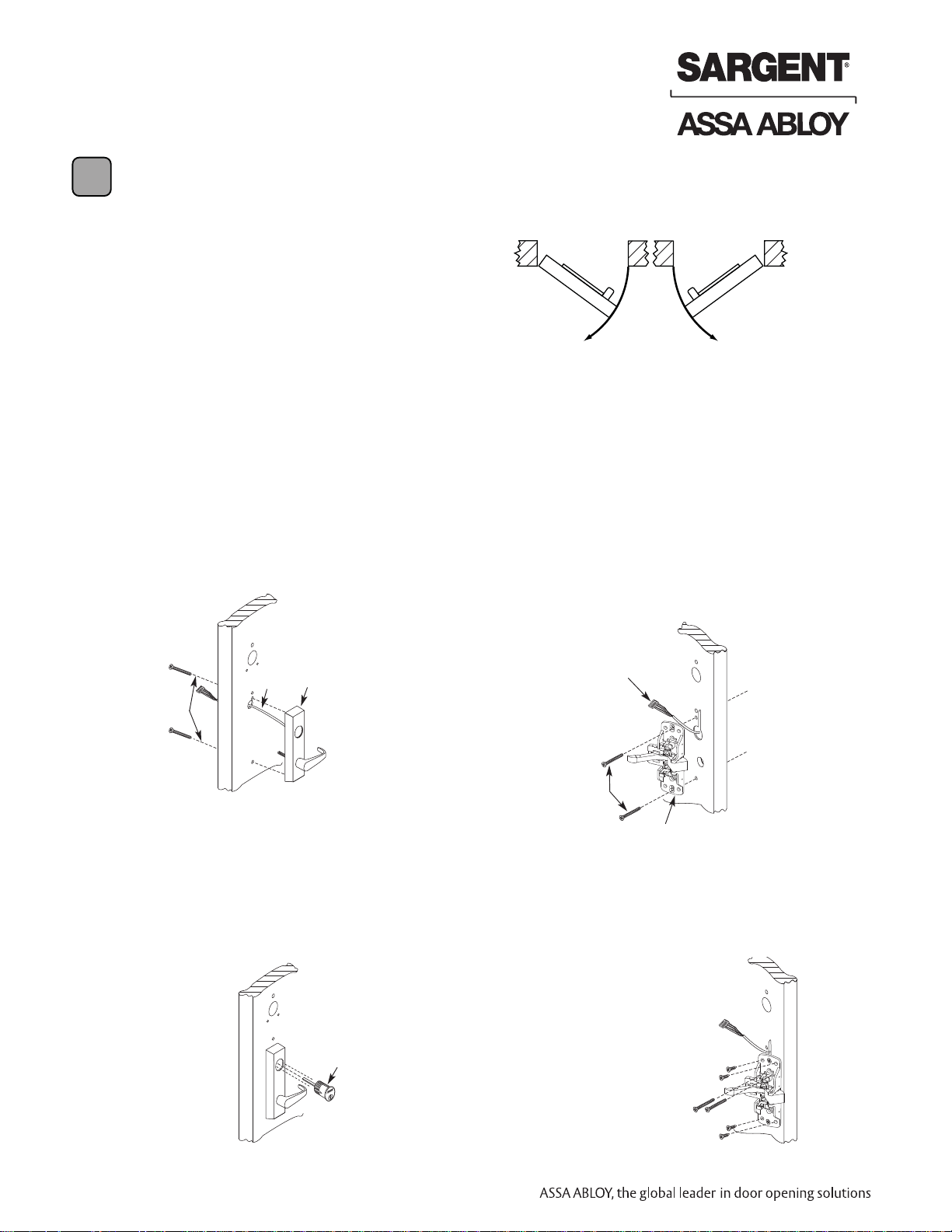
Installation Instructions for Mortise Type Exit
Device 8977/8978
Inside
Outside
Left Hand
Reverse Bevel
"LHRB"
Right Hand
Reverse Bevel
"RHRB"
NOTE: BEFORE STARTING
• Check hand of door - this
device is not reversible
• Door should be fitted and hung
• Verify box label for size of exit
device, function and hand
4
Step #1 - Exit Hardware & Door Prep
Prep door according to Exit installation instructions A6705
Page 11

9
800-810-WIRE (9473) • www.sargentlock.com • A7455B
Profile Series Exit Device
Copyright © 2003, 2008, Sargent Manufacturing Company, an ASSA ABLOY Group company. All rights reserved.
Reproduction in whole or in part without the express written permission of Sargent Manufacturing Company is prohibited.
Mortise Installation Instructions (Continued)
Step #2 – Install Outside & Inside Trim
Outside of door
Inside of door
(2) Flat
head
wood
screws
ET Spindle
ET Control
Wire
harness
Mortise lock
Connector
Exit Chassis
Centerline for
(2) 1/4 - 20 x 2-3/8’’
flat head
machine
screws
(2) 1/4 - 20 x 2 3/8’’
Flat head
machine screws
Wire
harness
Outside of
door
Inside of
door
Cylinder
set
screw
Cylinder
Correct Incorrect
Chassis
Lever
Latchbolt
Lever arm
(4) #10 Wood
screws
or #10-24
machine
screws
Figure 1
1. Exit Chassis:
• Route “ET” harness along track cutout for wood
doors and access hole for metal doors.
• Mount exit chassis carefully. Do not pinch
harness wires
• Position exit chassis on door so that lever arm is
under rear section of mortise lock lever. Then lift
up until latchbolt is completely retracted.
• Fasten exit chassis to door using (4) #10 wood
screws or #10-24 machine screws
2. Outside Trim
• Route harness through wire cutout and out to
other side of door
• Place “ET” control onto door
• Insert (2) 1/4-20 x 2-3/8 Flat head screws
• “ET” spindle will engage into mortise lock
3. Cylinder Installation
• Insert cylinder into “ET” control. Back out the
cylinder set screw in mortise lock
• Thread cylinder clockwise into mortise lock
until the cylinder sits flush and correct in
“ET” control (see figure 1)
• Tighten cylinder set screw
Page 12

10
800-810-WIRE (9473) • www.sargentlock.com • A7455B
Profile Series Exit Device
Copyright © 2003, 2008, Sargent Manufacturing Company, an ASSA ABLOY Group company. All rights reserved.
Reproduction in whole or in part without the express written permission of Sargent Manufacturing Company is prohibited.
Step #3 – Apply Fire Stop Plate (Required for 12-)
Inside of
door
Outside of
door
CL OF 1-1/2" Dia.
(2) Self tapping
screws #8 x 1/2"
long for wood &
metal doors
(2) 1/8" Dia. holes can
be drilled if the door is
not supplied with them
Slot
1-1/2'' Dia.
1-1/2''
7/8''
NOTE: Fire stop plate is required
on all fire rated doors
1. Fire stop plate for 12-devices
• Fire stop plate required in all fire rated doors (12-)
• Drill (2) 1/8" diameter holes if the door is not supplied with them
• Secure fire stop plate to door with (2) #8 x 1/2" self tapping screws
Mortise Installation Instructions (Continued)
Page 13

11
800-810-WIRE (9473) • www.sargentlock.com • A7455B
Profile Series Exit Device
Copyright © 2003, 2008, Sargent Manufacturing Company, an ASSA ABLOY Group company. All rights reserved.
Reproduction in whole or in part without the express written permission of Sargent Manufacturing Company is prohibited.
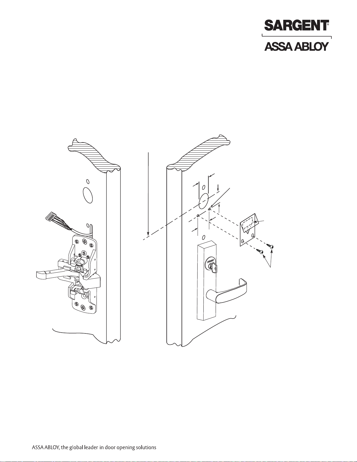
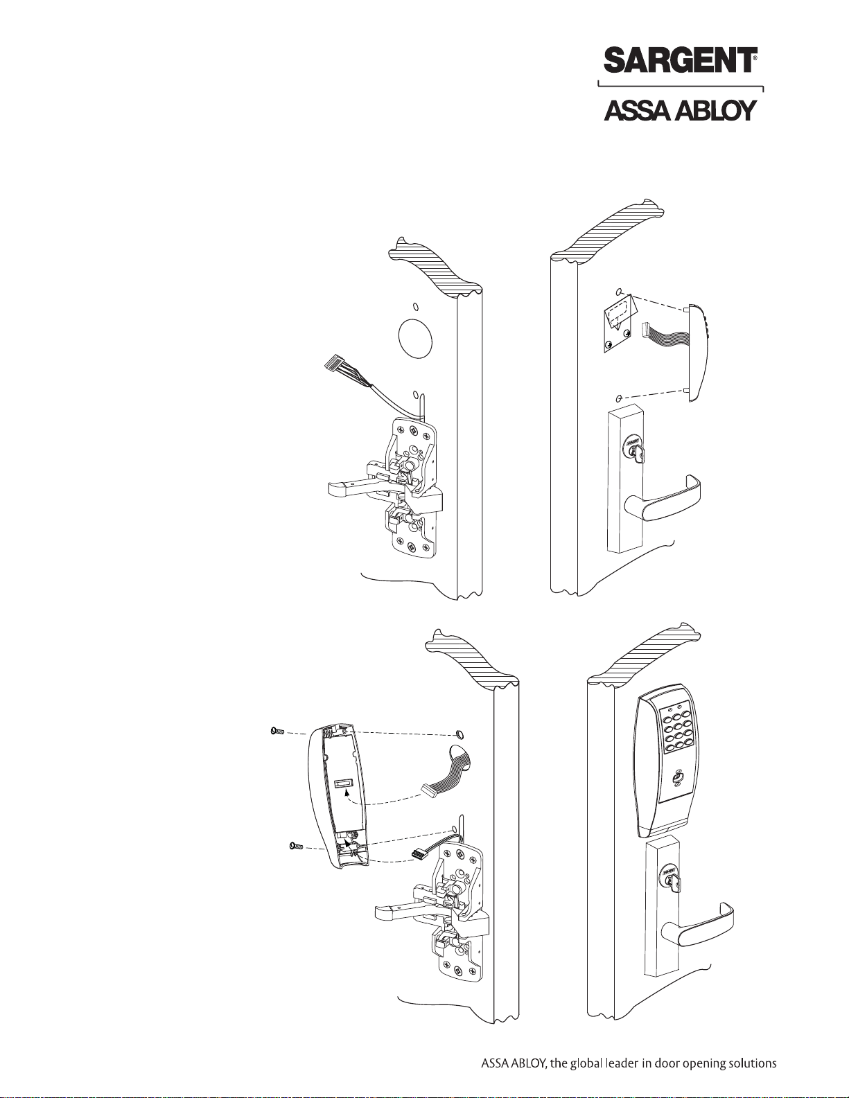
Step #4 – Outside Keypad Escutcheon
Mortise Installation Instructions (Continued)
Outside
of door
1. Insert Wires and Connector
• From the outside of the door through
the Fire Stop Plate (if required)
• For non 12- exit devices feed wire
harness from keypad assembly
through hole in door
• Straighten keypad escutcheon
and tighten the #8-32 x 1-1/4"
pan head screw
Inside
of door
Wires & Connector
go through fire
stop plate
Step #5 – Rail Assembly
Attach rail assembly according to Exit installation instructions A6705
Page 14

12
800-810-WIRE (9473) • www.sargentlock.com • A7455B
Profile Series Exit Device
Copyright © 2003, 2008, Sargent Manufacturing Company, an ASSA ABLOY Group company. All rights reserved.
Reproduction in whole or in part without the express written permission of Sargent Manufacturing Company is prohibited.
The Keypad Lock can support 100 (LK) / 500 (LU, PK, PA) users. Each user is assigned a
User Number in addition to the code used for entry.
Example:
USER USER USER CODE
TYPE NUMBER (2-6 DIGITS)
Master 01 1 2 3 4
Emergency 02 2 2 2 2
Supervisor 03 3 0 3 0 3 0
Standard 04-97 (LK) 2 6 5
04-500 (LU, PK, PA))
Programming Instructions for Keypad Operations
Only
6
Operational Check
5
• Place key into cylinder and rotate key
• The key will retract the latchbolt, the key should rotate freely
• Inside rail retracts latchbolt
• Enter 1234* to unlock outside lever handle and retract latchbolt
• If a card or prox is used, present them as shown below. Microprox Tags are presented
like cards.
Key/Cylinder, Code
Verification
Presentation of Card
or Tag
Presentation of Fob
Insert into dish
Page 15

13
800-810-WIRE (9473) • www.sargentlock.com • A7455B
Profile Series Exit Device
Copyright © 2003, 2008, Sargent Manufacturing Company, an ASSA ABLOY Group company. All rights reserved.
Reproduction in whole or in part without the express written permission of Sargent Manufacturing Company is prohibited.
Programming Instructions for
Keypad Operations Only
6
• Soflink™ Plus must be used with (PA) controller for programming
• The Master Code is always User “01”. The Master Code assigns the Emergency and
Supervisory Codes. It is also used for programming. Users are deleted through the Master
Programming Code only
• The Emergency Code is always User “02”. The Emergency Code has an unlock time of
10 seconds and entry when low battery expiration occurs
• The Supervisory Code is always User “03”. The Supervisory Code allows temporary lockout
of selected users, changes duration of unlock time, requests infrared interrogation output,
may add additional User Codes
• The first User Code will be User “04” or higher. User numbers do not have to be used or
entered sequentially
To Begin Programming:
The Lock Controller is preset at the factory with Master Code “1234”.
Entering 1234
*
will unlock the lock allowing the lever handle to retract the latchbolt.
Initial Set-Up Procedures:
• The following are typical procedures to follow when setting up your Exit Keypad
• If a mistake is made during any of procedures, depress the “*” several times until
the yellow LED goes out
• If no keystroke is made in a 30sec time frame the programming up to that point
will default and you will have to start over
LK Programming
To determine which programming steps to use for your lock see the example
below:
If your label has an LK, then use the programming below.
If your label has an LU or PK, turn to the next set of programming.
Change the Master Code
sknilb DEL wolleY*4321 #99
50# 1# Yellow LED blinks
ylkciuq sknilb DEL wolleY*edoC retsaM weN
ylwols sknilb DEL wolleY*edo
C retsaM weN
)eton ees ,dilos fI( tuo seog DEL wolleY*
This example uses the Factory Default 1234*, yours may differ.
It is recommended not to use the factory default master code.
-
+
-
+
-
+
-
+
+
-
+
-
LK
Page 16

14
800-810-WIRE (9473) • www.sargentlock.com • A7455B
Profile Series Exit Device
Copyright © 2003, 2008, Sargent Manufacturing Company, an ASSA ABLOY Group company. All rights reserved.
Reproduction in whole or in part without the express written permission of Sargent Manufacturing Company is prohibited.
To Enter the Emergency Code
sknilb DEL wolleY*edoC retsaM #99
sknilb DEL wolleY#2 #05
ylkciuq sknilb DEL wolleY*)stigid 6-1( ycneg
remE
)eton ees ,dilos fI( ylwols sknilb DEL wolleY*)stigid 6-1( ycnegremE
tuo seog DEL wolleY*
Emergency Code defaults to a 10 second unlock time
• Factory Default Emergency Code is 4321
To Change the Supervisor Code
sknilb
DEL wolleY*edoC retsaM #99
sknilb DEL wolleY#3 #1 #05
ylkciuQ sknilb DEL wolleY*)stigid 6-1( yrosivrepu
S
)eton ees ,dilos fI( ylwolS sknilb DEL wolleY*)stigid 6-1( yrosivrepuS
tuo seog DEL wolleY*
Enter A User Code
99# Master Code* or Supervisory Code* Yellow LED blinks
50# 1# (User Number 04-100)# Yellow LED blinks
ylkciuq
sknilb DEL wolleY*)stigid 6-1( edoC resU
)eton ees ,dilos fI( ylwols sknilb DEL wolleY*)stigid 6-1( edoC resU
tuo seog DEL wolleY*
Enter A Passage (Maintained) Code
sknilb DEL wolleY*edoC retsaM #99
50# 0# (User Number 04-100)# Yellow LED blinks
ylkciuQ sknilb DEL wolleY*)stigid 6-1(
edoC resU
)eton ees ,dilos fI( ylwols sknilb DEL wolleY*)stigid 6-1( edoC resU
tuo seog DEL wolleY*
Enter A One Time User Code
99# Master Code* or Supervisory Code* Yellow LED blinks
50# 5# (User Number 04-100)# Yellow LED blinks
yl
kciuQ sknilb DEL wolleY*)stigid 6-1( edoC resU
)eton ees ,dilos fI( ylwols sknilb DEL wolleY*)stigid 6-1( edoC resU
tuo seog DEL wolleY*
To Deactivate / Reactivate "Beep" With Key Stroke
99# Supervisory or Master Code* Yellow LED blinks
30# 0# 0# (Off) (1# = On) Yellow LED blinks
ylkciuq sknilb DEL wolleY*
)eton ees ,dilos fI( ylwols sknilb DEL
wolleY *
tuo seog DEL wolleY*
Note: If turning Beep OFF, Not audible on last two steps.
To Clear the Entire Memory
sknilb DEL wolleY*edoC retsaM #99
sknilb DEL wolleY#00000 #00000 #64
yl
kciuq sknilb DEL wolleY*
knilb ot snigeb dna dilos seog DEL wolleY *
)eton ees ,dilos fI( tuo seog DEL
wolleY*
This deletes ALL Codes, including Master, Emergency and Supervisory. The Master Code is set
back to 1234*, Door Number to 0001 and Unlock Time to 5 seconds. If the Master Code is not
known, Factory Assistance will be required to clear the memory. Call 1-800-810-9473.
Page 17

15
800-810-WIRE (9473) • www.sargentlock.com • A7455B
Profile Series Exit Device
Copyright © 2003, 2008, Sargent Manufacturing Company, an ASSA ABLOY Group company. All rights reserved.
Reproduction in whole or in part without the express written permission of Sargent Manufacturing Company is prohibited.
For additional information, see “Transaction Log”.
To LED
location
Infrared
Printer
(52-2069)
Door Name 5666
Seq User Trans
0 001 —
1 003 —
2 003 —
3 020 —
4 003 —
Transaction
Number
Transaction
Type
User
Number
Door
Name
Note: Seq. # 0 is the
programming request
to output the entries.
Sequence numbers
1-9 are the actual
entries.
Hold an infrared printer up to the infrared LED
(as shown). An HP82240B Infrared Printer
can be used to download information from the
keypad to a printout.
To Program Door Name into Keypad
sknilb DEL wolleY*edoC retsaM #99
43# Door Name (up to 5 digits)# Yellow LED blinks
ylkciuq sknilb DEL wolleY#0
)eton ees ,dilos fI( ylwols sknilb DEL
wolleY*
tuo seog DEL wolleY*
*
To Interrogate Transaction Log
99# Supervisory or Master Code* Yellow LED blinks
sknilb DEL wolleY #0 #0 #07
ylkciuq sknilb DEL wolleY*
)eton ees ,dilos fI( tuo seog DEL wolleY*
When done printing, the green LED will turn off
and the yellow LED will blink slowly.
tuo seog DEL wolleY *
To Reset / Clear Transaction Log
sknilb DEL wolleY*edoC retsaM #99
sknilb DEL wolleY#
00000 #00000 #67
ylkciuq sknilb DEL wolleY*
ylwols sknilb DEL wolleY*
)eton ees ,dilos fI( tuo seog DEL
wolleY *
To Delete A User
sknilb DEL wolleY*edoC retsaM #99
50# 1# (User Number 04-100)# Yellow LED blinks
ylkciuq sknilb DEL wolleY*
)eton ees ,dilos fI( ylwols sknilb DEL wolleY*
tuo seog DEL wolleY*
Var ies
Page 18

16
800-810-WIRE (9473) • www.sargentlock.com • A7455B
Profile Series Exit Device
Copyright © 2003, 2008, Sargent Manufacturing Company, an ASSA ABLOY Group company. All rights reserved.
Reproduction in whole or in part without the express written permission of Sargent Manufacturing Company is prohibited.
To Enable/Disable A User
sknilb DEL wolleY*edoC retsaM #99
56# 0# (Enable) or 1# (Disable)
sknilb DEL wolleY#)001-40 .oN resU(
ylkciuq sknilb DEL wolleY*
)eton
ees ,dilos fI( ylwols sknilb DEL wolleY*
tuo seog DEL wolleY*
To Set Unlock Time
sknilb DEL wolleY*edoC retsaM #99
sknilb
DEL wolleY#0 #)ces 99-1( #11
ylkciuq sknilb DEL wolleY*
)eton ees ,dilos fI( ylwols sknilb DEL wolleY*
tuo seog DEL wolleY*
The Unlock Time is adjustable for Momentary Operation. A 5 second unlock time is
recommended to extend battery life. Once the unlock time is entered, it is the same for
ALL users except 02.
Status Indicators
No Green LED after code is entered once, but flashes after 3 consecutive entries- Invalid Code
4 Long beeps after code is entered - Low Battery.
4 long beeps after code is entered, 4 more long beeps -Voltage (batteries) to low to operate
Enter Emergency Code to gain 1 entry.
LU and PK Programming
To determine which programming steps to use for your lock see the example
below:
If your label has a LU or PK then use the programming below.
If your label has a LK turn to LK programming.
Change the Master Code
sknilb DEL wolleY*4321 #99
sknilb DEL wolleY#1 #05
ylkciuq sknilb DEL wolleY*edoC retsaM weN
)eton ee
s ,dilos fI( ylwols sknilb DEL wolleY*edoC retsaM weN
tuo seog DEL wolleY*
This example uses the Factory Default 1234*, yours may differ.
It is recommended not to use the factory default master code.
To Enter the Emergency Code
sknilb DEL wolleY*edoC ret
saM #99
sknilb DEL wolleY#2 #05
ylkciuq sknilb DEL wolleY*)stigiD 6-1( ycnegremE
)eton ees ,dilos fI( yl
wols sknilb DEL wolleY*)stigiD 6-1( ycnegremE
tuo seog DEL wolleY*
Emergency Code default to a 10 second unlock time
• Factory Default Emergency Code is 4321
-
+
-
+
-
+
-
+
+
-
+
-
LU PK
Page 19

17
800-810-WIRE (9473) • www.sargentlock.com • A7455B
Profile Series Exit Device
Copyright © 2003, 2008, Sargent Manufacturing Company, an ASSA ABLOY Group company. All rights reserved.
Reproduction in whole or in part without the express written permission of Sargent Manufacturing Company is prohibited.
To Change the Supervisor Code
sknilb DEL wolleY*edoC retsaM #99
sknilb DEL wolleY#3 #1 #05
ylkciuq sknilb DEL wolleY*)stigid 6-1( yr
osivrepuS
)eton ees ,dilos fI( ylwols sknilb DEL wolleY*)stigid 6-1( yrosivrepuS
tuo seog DEL wolleY*
Enter A User Code
s
knilb DEL wolleY*edoC retsaM #99
50# 1# (User Number 04-500)# Yellow LED blinks
ylkciuq sknilb DEL wolleY*)stigid 6-1( edoC resU
)eton ees ,dilos fI(
ylwols sknilb DEL wolleY*)stigid 6-1( edoC resU
tuo seog DEL wolleY*
Enter A Passage (Maintained) Code
sknilb DEL wolleY*edoC retsaM #99
50# 0# (User Number 04-500)# Yellow LED blinks
ylkciuq sknilb DEL wolleY*)stigid 6-1( edoC resU
)eton ees ,dilos fI( ylwols sknilb DEL wolleY*)stigid 6-1( edoC resU
tuo seog DEL wolleY*
Enter A One Time User Code
sknilb DEL wolleY*edoC retsaM #99
50# 5# (User Number 04-500)# Yellow LED blinks
ylkciuq sknilb DEL wolleY*)st
igid 6-1( edoC resU
)eton ees ,dilos fI( ylwols sknilb DEL wolleY*)stigid 6-1( edoC resU
tuo seog DEL wolleY*
Enter a Card, Tag or Fob User
sknilb DEL wolleY*edoC retsaM #99
50# 1# (User Number 04-500)# Yellow LED blinks
ylkciuq sknilb DEL wolleY*
)eton ees ,dilos fI( ylwols sknilb
DEL wolleY*
Present Card, Tag or Fob BEEP / Yellow LED blinks
ylwols sknilb DEL wolleY*
tuo seog DEL wolleY*
Enter a User Code + Card, Tag or FOB
sknilb DEL wolleY*edoC retsaM #99
50# 1# (User Number 04-500)# Yellow LED blinks
ylkciuq
sknilb DEL wolleY*)stigid 6-1( edoC resU
)eton ees ,dilos fI( ylwols sknilb DEL wolleY*)stigid 6-1( ed
oC resU
Present Card, Tag or Fob BEEP / Yellow LED blinks
ylwols sknilb DEL wolleY*
tuo seog DEL wolleY*
Page 20

18
800-810-WIRE (9473) • www.sargentlock.com • A7455B
Profile Series Exit Device
Copyright © 2003, 2008, Sargent Manufacturing Company, an ASSA ABLOY Group company. All rights reserved.
Reproduction in whole or in part without the express written permission of Sargent Manufacturing Company is prohibited.
To Clear the Entire Memory
sknilb DEL wolleY*edoC retsaM #99
sknilb DEL wolleY#00000 #00000 #64
ylkciuq sknilb DEL wolleY*
wols ne
ht ,.ces 01 rof tsaf yrev sknilb DEL wolleY*
tuo seog DEL wolleY*
Turn OFF Audio Beep verification on every Key Depression
sknilb DEL wolleY*edoC retsaM #99
30# 0# 0# (Off) (1# = On) Yellow LED blinks
ylkciuq sknilb DEL wolleY*
)eton ees ,dilos fI( ylwols sknilb DEL wolleY*
tuo seog DEL wolleY*
Turn ON Yellow LED verification on every Key Depression
sknilb DEL wolleY*edoC retsaM #99
30# 1# 1# (On) (0# = Off) Yellow LED blinks
ylkciuq sknilb DEL wolleY*
)eton ees ,dilos fI( ylwols sknilb DEL wolleY*
tuo seog DEL wolleY*
Set Time
sknilb DEL wolleY*edoC retsaM #99
41# hh:mm# (24hr Format) 0# Yellow LED blinks
ylkciuq sknilb DEL wolleY*
)eton ees ,dilos fI( ylwols sknilb DEL wolleY*
tuo seog DEL wolleY*
24Hr Format = 1PM = 13, 2PM = 14.......10PM = 22, Midnight = 00 Example 13:15 = 1:15PM
Daylight Savings Time
sknilb DEL wolleY*edoC retsaM #99
30# 13# 1# (On) (0# = Off) Yellow LED blinks
ylkciuq sknilb DEL woll
eY*
)eton ees ,dilos fI( ylwols sknilb DEL wolleY*
tuo seog DEL wolleY*
Set Date (Today’s Date)
sknilb DEL wolleY*edoC retsaM #99
42# mmddyy# D.O.W.# (Sunday=1) Yellow LED blinks
ylkciuq sknilb DEL wolleY*
)eton ees ,dilos fI( ylwols sknilb DEL wolleY*
tuo seog DEL wolleY*
D.O.W. = Day of week
Page 21

19
800-810-WIRE (9473) • www.sargentlock.com • A7455B
Profile Series Exit Device
Copyright © 2003, 2008, Sargent Manufacturing Company, an ASSA ABLOY Group company. All rights reserved.
Reproduction in whole or in part without the express written permission of Sargent Manufacturing Company is prohibited.
To LED
location
Infrared
Printer
(52-2069)
Hold printer up to the infrared LED (as
shown). An HP82240B Infrared Printer can be
used to download information from the keypad
to a printout.
Set Unlock Time
sknilb DEL wolleY*edoC retsaM #99
sknilb DEL wolleY #0 #).ces 99-1( #11
ylkciuq sknilb DEL wolleY*
)eto
n ees ,dilos fI( ylwols sknilb DEL wolleY*
tuo seog DEL wolleY*
The Unlock Time is adjustable for momentary operation. A 5 second unlock time is recommended to extend battery life. Once the unlock time is entered, it is the same for ALL users except 02.
To Enable/Disable A User
sknilb DEL wolleY*edoC retsaM #99
56# 0# (Enable) or 1# (Disable)
skn
ilb DEL wolleY#)005-40 .oN resU(
ylkciuq sknilb DEL wolleY*
)eton ees ,dilos fI( ylwols sknilb DEL woll
eY*
tuo seog DEL wolleY*
To Delete A User
sknilb DEL wolleY*edoC retsaM #99
50# 1# (User Number 04-500)# Yellow LED blinks
ylkciuq sknilb DEL wolleY*
)eton ees ,dilos
fI( ylwols sknilb DEL wolleY*
tuo seog DEL wolleY*
To Interrogate Transaction Log Using IR Printer (52-2069)
sknilb DEL wolleY*edoC retsaM #99
sknilb DEL wolleY#
0 #0 #07
ylkciuq sknilb DEL wolleY*
derarfni ot retnirp tnioP ,tsaf neerG ,knilb wolleY*
LED. The printer will start to record the
transactions. When done printing, the Green LED
will turn off and the Yellow LED blinks slow.
Transactions STOP.
tuo seog DEL
wolleY*
For additional
information, see
“Transaction Log”.
Page 22

20
800-810-WIRE (9473) • www.sargentlock.com • A7455B
Profile Series Exit Device
Copyright © 2003, 2008, Sargent Manufacturing Company, an ASSA ABLOY Group company. All rights reserved.
Reproduction in whole or in part without the express written permission of Sargent Manufacturing Company is prohibited.
To Erase Transaction Log
sknilb DEL wolleY*edoC retsaM #99
sknilb DEL wolleY#00000 #00000 #67
ylkciuq sknilb DEL wolleY*
)eton e
es ,dilos fI( ylwols sknilb DEL wolleY*
tuo seog DEL wolleY*
Note: If the Yellow LED becomes solid rather than blinking, a mistake has been made.
Depress the * Button until the Yellow LED goes out and start programming again.
Status Indicators
3 very rapid beeps after User Code entered - Invalid User Code
4 long beeps after User Code entered - Low Battery Indication
4 long beeps after User Code entered, 4 more long beeps - Voltage too low to operate. Enter
Master or Emergency Code to gain 1 entry
1 beep after User Code entered - disabled user
4 beeps after User Code entered - deadbolt thrown
3 beeps after User Code entered - user lockout
Alternating red/green LED — Awaiting second entry of Code/Card, Tag or Fob user
PA Programming
To determine which programming steps to use for your lock see the example
below:
If your label has a PA and no keypad or front bezel then use the
programming below.
If your label has an LK turn to LK Programming.
If your label has an LU or PK turn to LU or PK Programming
In a Prox Only (PA) configuration, all programming must be completed using SofLink™ Plus
Software. The Software includes a convenient Software User’s Manual, to be used as a
programming guide.
-
+
-
+
-
+
-
+
+
-
+
-
PA
Comm Enable
Push Button
Page 23

21
800-810-WIRE (9473) • www.sargentlock.com • A7455B
Profile Series Exit Device
Copyright © 2003, 2008, Sargent Manufacturing Company, an ASSA ABLOY Group company. All rights reserved.
Reproduction in whole or in part without the express written permission of Sargent Manufacturing Company is prohibited.
Reprogramming
1. With Card selected as a "CommEnable" User Type programmed with SofLink Plus
Software. When this is done, presenting the "CommEnable" prox card to the lock will
allow the unit to wake up and initiate the communications channel to the PC without
the
need to press the CommEnable push button. Follow "First Time Programming" procedure,
except skip step 5.
2. With Card previously programmed (other than CommEnable User Type). Follow
"First Time Programming" procedure.
First Time Programming
(Using any HID Card and the PA controller
Comm Enable push button)
Note: Card can also be a Fob or Prox Tag
1. Create / Open Door File for PA Lock
2. Connect lock to PC (or PDP) using
connectors and cable
3. On PC - Click "Send to Door"
On PDP – Click "Up/Down"
4. Wake up the PA lock by presenting a HID
Card at the PA prox assembly.
5. Within a couple seconds
press and hold the
PA controller Comm Enable push button for
2 seconds, then release the button
6. On PC or PDP, click “OK”
7. Click OK. If there was an error, check
connections and repeat process starting at
Step 2.
8. *The Card will NOT
signal the lock for 45
seconds from the start of the downloading
process. After this time expires, the card
should function as indicated by its User
Type.
Message appears on PC "Please
enter your communication code at
the controller and then click OK."
Do NOT
click OK at this point
PA prox assembly - Green LED
flashes and lock beeps several
times
The PC or PDP starts transfering
the door file to the PA lock. When
finished, PC Displays "Transfer
Complete"
Page 24

22
800-810-WIRE (9473) • www.sargentlock.com • A7455B
Profile Series Exit Device
Copyright © 2003, 2008, Sargent Manufacturing Company, an ASSA ABLOY Group company. All rights reserved.
Reproduction in whole or in part without the express written permission of Sargent Manufacturing Company is prohibited.
Using Master Code 4732 and above information, the lock would be programmed as follows:
99# 4732* 50# 1# 05# 875* 875* 3# 12# 2226* 2226* 2# 08# 5444* 5444* 1# 50# 3367* 3367*
If all user codes are type 1, it is not necessary to enter the type number with each entry.
The format now simplifies to:
99# Master or Supervisor Code* User Number a# User code a* User Code a* UNb# UCb* UCb*
UNc# UCc* UCc*....... UN_# UC_* UC_**
An example with three user codes is shown below:
Using Master Code 45988 and above information, the lock would be programmed as follows:
99# 45988* 07# 77* 77* 15# 67832* 67832* 91# 7568* 7568**
To chain the User Number delete procedure:
99# Master Code* User Number a#** UNb#** UNc#**....... UN_#****
Using the information from the above example:
99# 45988* 07#** 15#** 91#****
Type User Number User Code
107 77
1 15 67832
1 91 7568
Chain Programming
7
When programming multiple User Numbers and Codes into the LK, LU or PK Keypad Lock, it is
not necessary to leave and re-enter the programming Mode (50) for each entry. Multiple entries
may be chained together and the three different types of user codes (Standard, Passage and
One Time) may be mixed.
The format to be used is as follows where:
“T” is the Type of user code with “1” Standard, “2” Passage and “3” One Time.
“UN_” is User Number (04-99)
“UC_” is User Code (2 to 6 digits) which correlates with the User Number
99# Master or Supervisor Code* 50# Type# User Number a# User Code a*
User Code a* T# UNb# UCb* UCb* T# UNc# UCc* UCc* ...... T# UN_# UC_* UC_**
An example with four user codes is shown below:
Type User Number User Code
578501
6222213
4445802
7633051
-
+
-
+
-
+
-
+
+
-
+
-
LK LU PK
Page 25

23
800-810-WIRE (9473) • www.sargentlock.com • A7455B
Profile Series Exit Device
Copyright © 2003, 2008, Sargent Manufacturing Company, an ASSA ABLOY Group company. All rights reserved.
Reproduction in whole or in part without the express written permission of Sargent Manufacturing Company is prohibited.
Door Name
• If SofLink™ Plus is used, door name must be changed via PC
Sequence Number
• Single digit - 0-9
• Latest transaction - 0
• Oldest transaction - 9
User Number
• Three digits - 001 through 099
• User numbers assigned at time of programming
Transaction Descriptions
• Will vary
Optional Equipment
• Printer Paper (6 Rolls) - 52-0034 used for infrared
printers
• Infrared Printer - 52-2069 - used to download the
user and transaction type.
• Remote Unlocking - 52-2071 - used for remote
unlocking of low profile mortise lock. When the
deadbolt is thrown and the remote unlocking feature
is used, both the latchbolt and deadbolt can be
retracted by turning the lever handle.
Transaction Log
8
To output the last 15 or 1000 transactions, enter 99 # Supervisory or
Master Code *70 # 0 # 0 # **.
• Examples on this page are for
the 100 user, 15 transaction unit
To LED
location
Infrared
Printer
(52-2069)
Door Name 5666
Seq User Trans
0001
—
1 003 —
2 003 —
3 020 —
4 003 —
Transaction
Number
Transaction
Type
User
Number
Door
Name
Note: Seq. # 0 is the programming
request to output the entries.
Sequence numbers 1-9 are
the actual entries.
Hold an infrared printer up to the infrared
LED (as shown). An HP82240B Infrared
Printer can be used to download information
from the keypad to a printout.
-
+
-
+
-
+
-
+
+
-
+
-
LK
Var ies
Page 26

24
800-810-WIRE (9473) • www.sargentlock.com • A7455B
Profile Series Exit Device
Copyright © 2003, 2008, Sargent Manufacturing Company, an ASSA ABLOY Group company. All rights reserved.
Reproduction in whole or in part without the express written permission of Sargent Manufacturing Company is prohibited.
Supplemental – Individual “Door” Log Sheet (LK, LU, PK and PA)
Lock Model:
Door Name:
Location:
Table 1: Main Codes - User Programmed “Door” Log
Function User Number Default Code User Programmed Code
Master Code 01 1234*
Emergency Code 02 4321*
Supervisory Code 03
Table 2: User Programmed “Door” Log
User Name User Type User Number User Code Card/Fob#, Notes
*Note: If entire memory is cleared, you must reprogram Emergency code. The Master code
resets back to 1234*.
Page 27

25
800-810-WIRE (9473) • www.sargentlock.com • A7455B
Profile Series Exit Device
Copyright © 2003, 2008, Sargent Manufacturing Company, an ASSA ABLOY Group company. All rights reserved.
Reproduction in whole or in part without the express written permission of Sargent Manufacturing Company is prohibited.
Notes:
Page 28

A7455B-12/08
SARGENT Manufacturing
100 Sargent Drive
New Haven, CT 06511 USA
800-727-5477 • www.sargentlock.com
Founded in the early 1800s, SARGENT®is a market leader in locksets, cylinders, door closers, exit devices,
electro-mechanical products and access control systems for new construction, renovation, and replacement applications.
The company’s customer base includes commercial construction, institutional, and industrial markets.
Copyright © 2003, 2008 Sargent Manufacturing Company, an ASSA ABLOY Group company. All rights reserved.
Reproduction in whole or in part without the express written permission of Sargent Manufacturing Company is prohibited.
ASSA ABLOY is the global leader in door opening solutions, dedicated to
satisfying end-user needs for security, safety and convenience.
 Loading...