

Sargent Profile Series Installation Instructions Manual
v.G1.5
Profile Series
Dorm Lock
Installation Instructions
A7861C
11/17
Copyright 2017, Sargent Manufacturing Company, an ASSA ABLOY Group company.
All rights reserved. Reproduction in whole or in part without the express written
permission of Sargent Manufacturing Company is prohibited.
Table of Contents
Warning ...................................................................................2
1
2
General Description .................................................................3
3
Specifications ..........................................................................3
4
Features ...................................................................................3
5
Parts Breakdown .....................................................................4
6
Installation Instructions ..........................................................6
7
RF Technology Lock ...............................................................15
8
Hardwire Wiring Options .......................................................16
9
Operational Check .................................................................21
Warning
1
This device complies with Part 15 of the FCC Rules. Operation is subject to the following two conditions: (1) this
device may not cause harmful interference, and (2) this device must accept any interference received, including
interference that may cause undesired operation.
Note: This equipment has been tested and found to comply with the limits for a Class B digital device, pursuant to
Part 15 of the FCC Rules. These limits are designed to provide reasonable protection against harmful interference in
a residential installation.
This equipment generates, uses and can radiate radio frequency energy and if not installed and used in accordance
with the instructions, may cause harmful interference to radio communications. However, there is no guarantee that
the interference will not occur in a particular installation. If this equipment does cause harmful interference to radio or
television reception, which can be determined by turning the equipment off and on, the user is encouraged to try to
correct the interference by one or more of the following measures:
• Reorient or relocate the receiving antenna
• Increase the separation between the equipment and receiver
• Connect the equipment into an outlet on a circuit different from that to which the receiver is connected
• Consult the dealer or an experienced TV technician for help
This Class B digital apparatus complies with Canadian ICES-003.
Cet appareil numérique de la classe B est conforme avec la norme NMB-003 du Canada.
To comply with “Fire Listed” doors, the batteries must be replaced with alkaline batteries only.
!
Do not install batteries if controller is powered by external power supply.
Warning SARGENT Mfg. Co. locksets utilizing a door position switch (DPS)
!
are not rated for, or intended for use in life safety applications.
Changes or modifications to this unit not expressly approved by the party
responsible for compliance could void the user’s authority to operate the equipment.
Copyright © 2017, Sargent Manufacturing Company, an ASSA ABLOY Group company. All rights reserved.
Reproductions in whole or in part without express written permission of Sargent Manufacturing Company is prohibited.
11/11/11
1-800-810-WIRE • www.sargentlock.com • A7861C
Profile Series v.G1.5 Mortise Dorm Lock
2
General Description
The SARGENT Profile Series v.G1.5 Mortise Dorm Lock is designed to prevent residents from being locked
out of their rooms. The resident presents a proximity card and/or pin code, which works as a toggle to unlock
(overriding the deadbolt if thrown) or relock the outside lever. When entering a room, the deadbolt locks the
outside lever. When exiting the room, retracting the deadbolt unlocks the outside lever.
If the outside lever is locked and the deadbolt is not thrown, rotating the inside lever will unlock the outside
lever (via the lockbody’s inside monitor switch).
The resident must present their prox card and/or pin code to relock the door.
It is a self-contained microprocessor-controlled keypad with non-volatile memory. The keypad holds a total
of 100 (LK)/2000 (G1-LU, G1-PK, G1-PA, G1-TU, G1-TP, G1-TA) different user codes. User codes 01 and 02 are
utilized for Master and Supervisory Codes, respectively. SARGENT mortise locks are designed with quality
components to provide high security, performance and durability.
This product is operated by six (6) “AA” alkaline* batteries.
3
Specifications
• Latch - Stainless steel
• Deadbolt - Stainless steel
• Guardbolt - Stainless steel, non handed
• Handed - Easily field reversible without
disassembling the lock body
• Case - 12 gauge heavy duty wrought steel
• Outside lever controlled by any combination
of keypad, proximity or RF technology
• Inside lever retracts latch and deadbolt
• Locks furnished for 1-3/4" doors. Can be furnished
for other door sizes upon request.(Consult factory)
• U.L. Listed (3 hr.)
4
Features
• Non-volatile memory
• Motor driven, battery operated
• Battery operated with 6 “AA” Alkaline
• Low battery alert: 4 chirps after code entry
• External remote “Request to Enter”
• Master, Emergency or Supervisory code will
unlock door when low battery has expired
• Programming done at keypad or with a DTD
(Data Transfer Device) using SoloPlus™
software and a Laptop/PC (G1-TA and
G1-TP require software)
SoloPlus™ works with PalmPilot; SofLink™
Plus software not supported with DTD.
*To comply with “Fire Listed” doors, the batteries must be replaced with alkaline batteries only.
!
• RF Fob and Proximity Card, Tag, and
Fob are optional
• Operates utilizing any one to six digit code
• Digits may be repeated and codes may
start with zero
• Cylinder override
• Entry of three wrong User Codes disables all
codes for ten seconds. Yellow LED on solid
• Piezo horn can be heard with each keystroke
or turned off by Master or Supervisory Code
• Last 2000 (Except LK) transactions can be
output to PC via DTD/SoloPlus™ Software
Copyright © 2017, Sargent Manufacturing Company, an ASSA ABLOY Group company. All rights reserved.
Reproductions in whole or in part without express written permission of Sargent Manufacturing Company is prohibited.
1-800-810-WIRE • www.sargentlock.com • A7861C 3
11/30/17
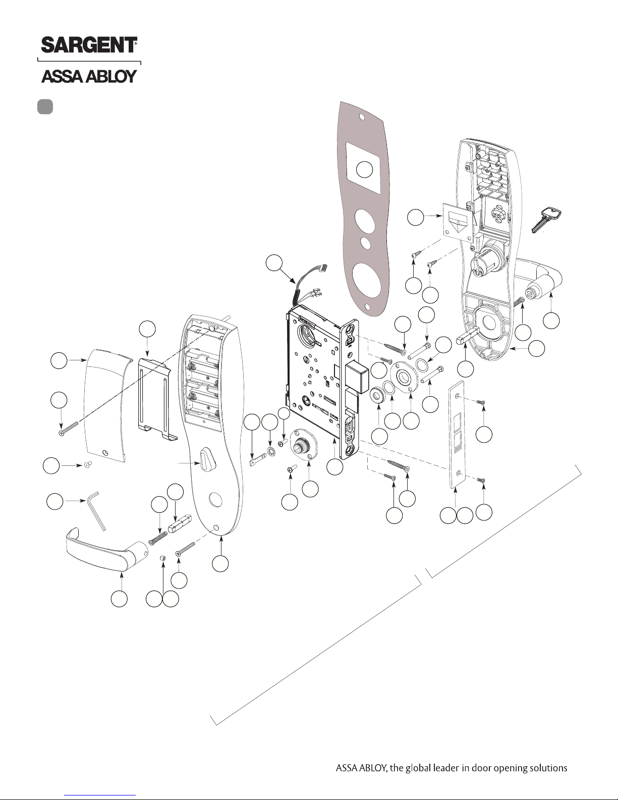
Parts Breakdown
Prole Series v.G1.5
5
Parts Breakdown
5
3
3
34
Profile Series v.G1.5 Mortise Dorm Lock
35
12
12
32
13
13
13
13
26
26
21
22
21
24
24
16
22
16
33
17
17
30
30
1
1
11
11
15
9
8
9
8
17
7
16
16
17
15
15
4
4
5
5
14
14
31
31
23
23
24
24
22
22
21
21
25
25
26
26
18/19
18 19
20
20
20
20
Outside
2
2
11
11
20
29
17
27/28
20
Inside
Copyright © 2017, Sargent Manufacturing Company, an ASSA ABLOY Group company. All rights reserved.
Reproductions in whole or in part without express written permission of Sargent Manufacturing Company is prohibited.
11/30/17
4 1-800-810-WIRE • www.sargentlock.com • A7861C
Profile Series v.G1.5 Mortise Dorm Lock
Parts Breakdown (Continued)
ITEM PART No. DESCRIPTION REQ’D
1 82-4190 Outside Escutcheon with Cylinder Hole and Key Pad, or Key
Pad/Prox (G1-LU, G1-PK, G1-TU, G1-TP)
82-4191 Outside Escutcheon without Cylinder Hole and Key Pad or Key
Pad/Prox (G1-LU, G1-PK, G1-TU, G1-TP)
82-4192 Outside Escutcheon with Cylinder Hole and Prox Only (G1-PA,
G1-TA)
82-4193 Outside Escutcheon without Cylinder Hole and Prox Only (G1-
PA, G1-TA)
82-0493 Outside Escutcheon Housing Only without Cylinder Hole
82-0495 Outside Escutcheon Housing Only with Cylinder Hole 1
52-2432 Keypad/Proximity Bezel Assembly w/ Harness (LK) 1
52-2706 Proximity Only Bezel Assembly with Harness (G1-PA, G1-TA) 1
52-2704 Key Pad/Proximity Bezel Assembly with Harness (G1-LU, G1-PK,
G1-TU, G1-TP)
2 82-3837 Inside Escutcheon with Thumb Turn and 100 User Controller (LK) 1
82-3838 Inside Escutcheon without Thumb Turn and 100 User Controller
(LK)
82-4182 Inside Escutcheon with Thumb Turn and 2000 User Controller
(G1-LU)
82-4183 Inside Escutcheon without Thumb Turn and 2000 User Controller
(G1-LU)
82-4184 Inside Escutcheon with Thumb Turn Prox/Key Pad Controller
(G1-PA, G1-PK)
82-4185 Inside Escutcheon without Thumb Turn Prox/Key Pad Cont.
(G1-PA, G1-PK)
82-4186 Inside Escutcheon with Thumb Turn & 2000 User Controller with
RF Technology (G1-TU)
82-4187 Inside Escutcheon without Thumb Turn & 2000 User Controller
with RF Technology (G1-TU)
82-4188 Inside Escutcheon with Thumb Turn & Keypad/Prox or Prox Only
Controller (G1-TA, G1-TP)
82-4189 Inside Escutcheon without Thumb Turn & Keypad Prox or Prox
Only Controller (G1-TA, G1-TP)
82-0492 Inside Escutcheon Housing Only without Thumb Turn 1
82-0494 Inside Escutcheon Housing Only with Thumb Turn 1
52-2440 100 (LK) User Key Pad Controller Assembly 1
52-2783 2000 (G1-LU) User Controller Assembly 1
52-2784 2000 User (G1-PA, G1-PK) Controller Assembly 1
52-2786 2000 User Keypad/Prox Controller Assembly with RF Technology
(G1-TA, G1-TP)
52-2785 2000 User Keypad Controller Assembly with RF Technology
(G1-TU)
3 52-0170 Battery Cover 1
52-2509 Battery Cover – RF Technology (G1-TU,G1-TP, G1-TA) 1
1
1
1
1
1
1
1
1
1
1
1
1
1
1
1
1
1
ITEM PART No. DESCRIPTION REQ’D
4 01-1212 Security Screw 1
5 01-0297 Security Tool 1
7 82-0507 Thumb Turn 1
8 77-0772 Spindle (Thumb Turn) 1
9 01-0844 Washer (Thumb Turn) 1
10 01-0543 Spring Grip Fastener (Thumb Turn) 1
11 77-0168 Through-bolts #8-32 x 1 7/8" Flat Head Screw 2
12 52-0033 Fire Stop Plate 1
13 01-1500 Fire Stop Screws #8 x 1/2" Type “AB” Phillips Pan Head
14 82-3088 Inside Spindle Adapter & Plate Assembly
15 01-1495 Screw #8-32 x 1/2"
16 82-0368 Inside Spindle/Outside Spindle
17 82-0347 Inside Spring/Outside Spring
18 82-0081 Face Plate no Dead Bolt
19 82-0084 Face Plate with Dead Bolt
20 01-1028 Face Plate Screws Machine 8-32 x 1/4"
21 01-2299 Lock Body Screws/Wood Door #12 x 1 1/4"
22 01-1019 Lock Body Screws/Metal Door 12-24 x 1/2"
23 82-0184 Cap Nut
24 01-0079 Washer
25 82-3082 Plate Assembly
26 81-0723 Post
27 01-1472 Lever Handle Screw, A, E & F Lever
28 01-1174 Lever Handle Screw, B, J, L, P & W Lever
29 Reference Profile Series catalog for available lever handles
30 Reference Profile Series catalog for available lever handles
31 G1-8276-hand-finish
G1-8277-hand-finish
G1-8278-hand-finish
G1-8279-hand-finish
32 01-0803 Battery Alkaline (“AA” cell - not shown)
33 52-0253 Battery Keeper
52-0344 Battery Keeper – RF Technology (G1-TU, G1-TP, G1-TA)
34 10-0649 Gasket, weatherseal
Self Tap
Lockbody Assembly with deadbolt & cylinder
Lockbody Assembly with deadbolt only (no cylinder)
Lockbody Assembly with cylinder only (no deadbolt)
Lockbody Assembly without deadbolt & without cylinder
1
2
1
2
2
2
1
1
2
2
2
1
2
1
2
1
1
1
6
1
1
1-800-810-WIRE • www.sargentlock.com • A7861C 5
Copyright © 2017, Sargent Manufacturing Company, an ASSA ABLOY Group company. All rights reserved.
Reproductions in whole or in part without express written permission of Sargent Manufacturing Company is prohibited.
11/30/17
Profile Series v.G1.5 Mortise Dorm Lock
6
Installation Instructions
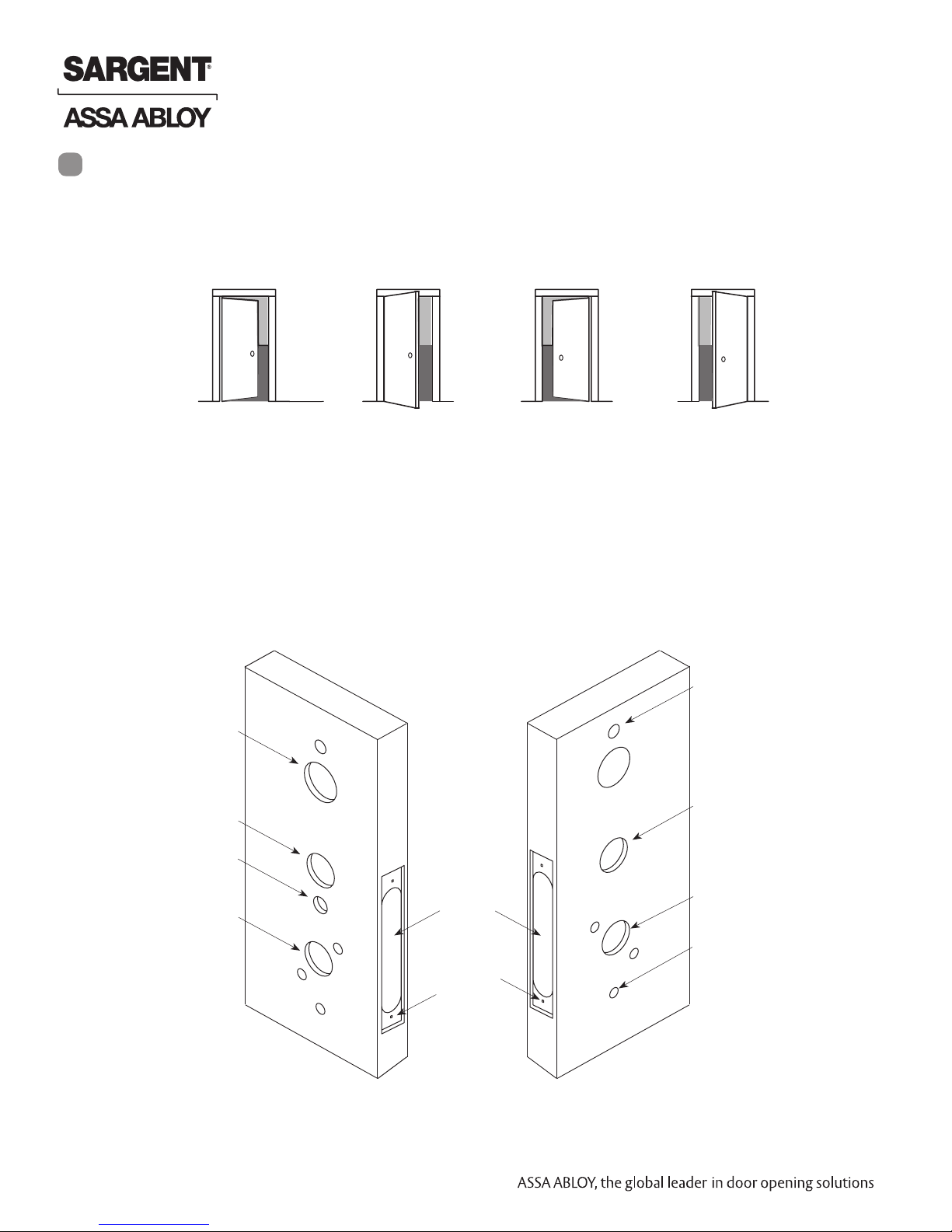
Step #1 – Verify Hand and Bevel of Door
A. Verify Hand and Bevel of Door
Stand on outside/locked side of door when determining the door hand
LH
Left Hand
Hinges Left
Open Inward
LHRB
Left Hand
Reverse Bevel
Hinges Left
RH
Right Hand
Hinges Right
Open Inward
Open Outward
Fig. 1A
B. Prepare Door
Prep door according to Instruction Sheet A7457 and appropriate template:
Manufacturer Door Template: 4533
Outside of DoorInside of Door
Ribbon Cable Hole
(Controller to Keypad)
Inside Cylinder Hole
Thumb Turn Lever Hole
RHRB
Right Hand
Reverse Bevel
Hinges Right
Open Outward
Through-bolt Hole
Outside Cylinder Hole
(76 and 78 Functions)
Lever Handle Hole
Copyright © 2017, Sargent Manufacturing Company, an ASSA ABLOY Group company. All rights reserved.
Reproductions in whole or in part without express written permission of Sargent Manufacturing Company is prohibited.
11/30/17
Fig. 1B Wood Door Preparation
6 1-800-810-WIRE • www.sargentlock.com • A7861C
Mortised
Pocket
Pre-drilled
and/or
Tapped Holes
(2 places)
Lever Handle Hole
Through-bolt Hole
Profile Series v.G1.5 Mortise Dorm Lock
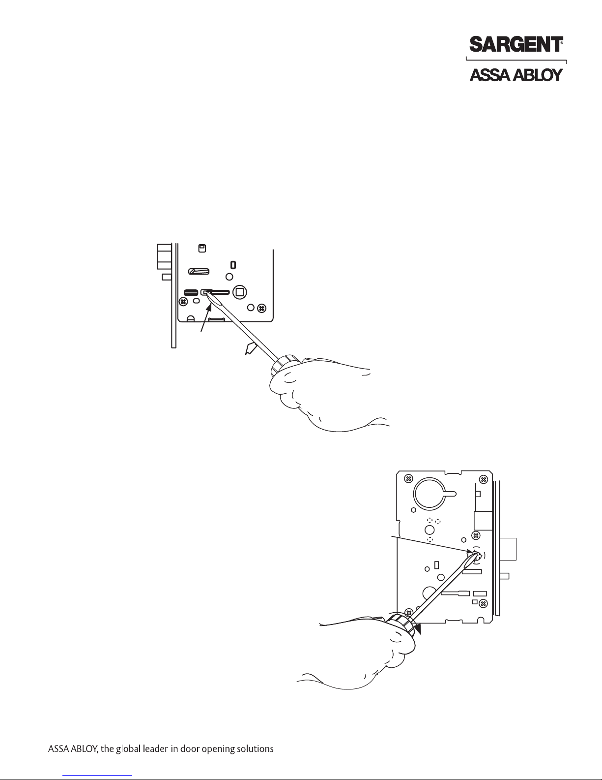
Step #2 – How to Change Hand of Lockbody
A. Reverse Lock Hand
Red surface of locking piece must face the outside/locked side of door. To rotate locking piece (Fig. 2A):
1. Position lock body with red surface of locking piece visible.
2. Insert blade type screwdriver into locking piece slot to rotate locking piece toward back of lock body.
3. Rotate the locking piece 180° until RED surface is on opposite side.
Note: Red indicates locked side (outside).
Right Hand
Lock Shown
Locking Slide
Red on Locked Side
Push In
Fig. 2A
B. Reverse Latch Hand
Beveled surface of latchbolt must face strike (Fig. 2B).
The deadlatch is self adjusting.
To change the hand of the latchbolt:
1. Insert the blade of a slotted screwdriver (>1/4")
into the spade shape slot behind latch.
2. Rotate the screwdriver 90° to push latchbolt out
until back of bolt clears lock case front.
3. Rotate latchbolt 180° until the latchbolt
drops back into the lock body.
Note: Latch cannot be unscrewed.
Spade
Shaped
Slot
Latchbolt
Deadlatch
Fig. 2B
1-800-810-WIRE • www.sargentlock.com • A7861C 7
Copyright © 2017, Sargent Manufacturing Company, an ASSA ABLOY Group company. All rights reserved.
Reproductions in whole or in part without express written permission of Sargent Manufacturing Company is prohibited.
11/30/17
 Loading...