

Sargent 2600 Series Instructions For Installation Manual

Instructions For
Installation and Programming
2600 Series
Low-Energy Swing Door
Operator
Push and Pull Applications
A7311D

1
TABLE OF CONTENTS
DOOR OPERATOR COMPONENTS . . . . . . . . . .2
WARNINGS AND GUIDELINES . . . . . . . . . . . . . .3
FEATURES AND FUNCTIONS . . . . . . . . . . . . . . .4
INSTALLATION PROCEDURE . . . . . . . . . . . . . . 4
Tools Required . . . . . . . . . . . . . . . . . . . . . . . .4
Identify Door Application . . . . . . . . . . . . . . . .4
Push Application Installation . . . . . . . . . . . 5-7
Pull Application Installation . . . . . . . . . . .8-10
Initial Electrical Connections . . . . . . . . . . . .11
Power Requirements/Connections . . . . . . .11
External Fire Alarm Connection . . . . . . . . . .12
Battery Alarm Wiring . . . . . . . . . . . . . . . . . .13
DETAILED PROGRAMMING . . . . . . . . . . . . . . . .14
Initial Set Up and Programming . . . . . . . . . .14
Programming with the Control Unit . . . . . . .14
Display and Program Buttons . . . . . . . . .14-16
Restore Factory Settings . . . . . . . . . . . . . . .15
Test the Unit . . . . . . . . . . . . . . . . . . . . . . . . .16
Display LED’s . . . . . . . . . . . . . . . . . . . . . . . .17
Programming a Control Point . . . . . . . . .18-19
Sealed Control Points . . . . . . . . . . . . . . . . .20
Control Points . . . . . . . . . . . . . . . . . . . . 21-24
Control Points Affecting Speed
and Closing Force . . . . . . . . . . . . . . . . . . .25
Programming Suggestions . . . . . . . . . . . . . .25
BATTERY OPERATION . . . . . . . . . . . . . . . . . . . .26
Fire Door Use . . . . . . . . . . . . . . . . . . . . . . . .26
Battery Tests . . . . . . . . . . . . . . . . . . . . . . . .26
Power Failure In Fire Door Mode . . . . . . . . .27
Fire Adapter . . . . . . . . . . . . . . . . . . . . . . . . .27
FUNCTIONS . . . . . . . . . . . . . . . . . . . . . . . . . . . .27
ELECTRICAL WIRING . . . . . . . . . . . . . . . . . . . .27
Control Unit Input/Output Connections
and Functions . . . . . . . . . . . . . . . . . . . . . .27
Typical Applications . . . . . . . . . . . . . . . . 28-31
HAND HELD PROGRAMMER . . . . . . . . . . . . . . .32
RESTORING TO FACTORY SETTINGS WITH
THE HAND HELD PROGRAMMER . . . . . . . .33
TROUBLESHOOT COMMON PROBLEMS . . . . .34
Common Problems . . . . . . . . . . . . . . . . . . .34
Error (E) Codes . . . . . . . . . . . . . . . . . . . . . . .34
2
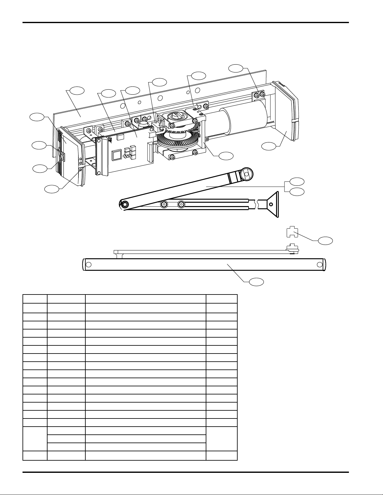
DOOR OPERATOR COMPONENTS
1
2
3
4
5
6
7
8
9
11
11
10
9
8
7
5
6
15
3
1
2
4
2651
2652
12
13
14
16
2660
ITEM PART NO. DESCRIPTION REQ.
1 63-3603 Main Switch 1
2 63-3600 Mode Selector Switch 1
3 63-0607 End Cover 1
4 63-3592 LED Electronics Assembly 1
5 63-3606 Control Unit Assembly 1
6 63-3604 Transformer Assembly 1
7 63-3599 Position Sensor 1
8 63-3605 Side Motor Mount 1
9 63-3602 Motor and Drive Gear Assembly 1
10 63-0606 End Cover 1
11 63-3601 Back Motor Mount 1
12 63-3593 Standard Arm—2651 1
13 63-3594 Extended Arm—2652 1
14 63-3595 Track Type Arm—2660 (Non-Handed) 1
15 63-0608 Mounting Plate 1
63-0603 Spindle Extension 3/8”
16 63-0604 Spindle Extensions 3/4” 1
63-0605 Spindle Extensions 2 3/8”
17 63-3596 Battery Pack (not shown) 1
3
WARNING
The SARGENT 2600 Series Low-Energy Door Operator is intended to be used in low-energy handicap
applications. Guidelines for low-energy can be found in ANSI Standard A156.19, American National Standard for
Power Assist and Low-Energy Power Operated Doors.
Generally speaking, low-energy doors move slowly, and therefore generate minimal levels of kinetic energy.
SARGENT recommends that the hold-open time for a low-energy door be not less than 10 seconds. Also, local fire
codes requirements for hold-open time should be taken into consideration.
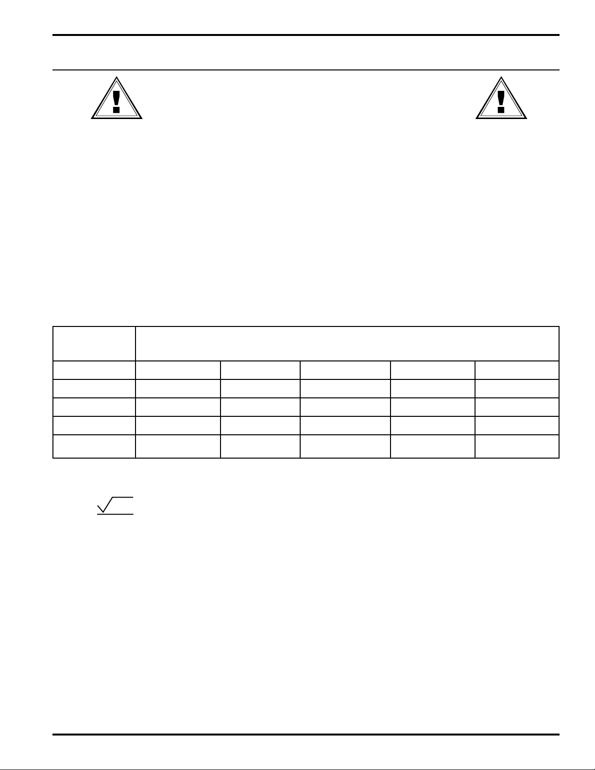
Minimum opening and closing times for doors of various widths and weights are summarized in the table below.
Minimum Opening Time to Back Check or 80 deg or
Minimum Closing Time from 90 deg to Latch Check or 10 deg
Doors of other weights and widths can be calculated using the formula:
T= D W Where: T = Time in sec
133 lb-ft D = Door width in inches
W = Door weight in lb
CLOSING FORCE MUST NOT EXCEED 15 LB FOR A LOW-ENERGY APPLICATION. IF CLOSING FORCE
EXCEEDS 15 LB, THE DOOR WILL NOT MEET THE REQUIREMENTS OF ANSI STANDARD A156.19, AMERICAN
NATIONAL STANDARD FOR POWER ASSIST AND LOW ENERGY POWER OPERATED DOORS.
LATCHING SPEED MUST BE SUCH THAT THE DOOR TAKES AT LEAST 1.5 SEC TO MOVE FROM LATCHING
SPEED STARTING POINT TO FULLY CLOSED.
WHEN INSTALLATION IS COMPLETE, SET CONTROL POINT 15 TO 1, FIRE DOOR MODE. WHEN A FIRE ALARM
IS ACTIVATED, THE DOOR IS OPENED MANUALLY AND CLOSED UNDER POWER. IF THIS SETTING IS NOT 1,
THE DOOR WILL NOT ACHIEVE UL COMPLIANCE.
WARNINGS AND GUIDELINES
“D” Door
Width in “W” Door Weight in Pounds
Inches
100 125 150 175 200
30 3.0 sec 3.0 sec 3.0 sec 3.0 sec 3.5 sec
36 3.0 sec 3.5 sec 3.5 sec 4.0 sec 4.0 sec
42 3.5 sec 4.0 sec 4.0 sec 4.5 sec 4.5 sec
48 4.0 sec 4.5 sec 4.5 sec 5.0 sec 5.5 sec

4
• Programmable door weight up to 275 lbs. (125 Kg)
• All functions are programmable at the Operator or using an optional hand held programmer.
• Door can be activated by a delayed or non delayed impulse (See wiring)
• Battery backup for closing during fire or loss of power
• Adjustable hold open time 0-60 seconds
• Push and go manual opening (Intended to assist physically challenged only)
• Built in 12 or 24 VDC power supply for external locking devices(800mA max @ 24VDC)
• Lock control relay NO/NC operation
• Concealed wiring, standard
PUSH APPLICA TION
PULL APPLICATION
PUSH APPLICA TION
PULL
APPLICATION
Identify your type of application. This value will be necessary for programming. The 2600 Series Swing Door
Operator can be installed in any of four applications:
CONTROL
POINT
14 = 0
CONTROL
POINT
14 = 1
Identify Door Application
GO TO APPLICABLE INSTALLATION INSTRUCTIONS ...
FEATURES AND FUNCTIONS
NOTE: DOOR STOP IS REQUIRED TO
ENSURE PROPER OPERATION
OF THE DOOR OPERATOR.
INSTALLATION PROCEDURE
Tools Required
• Electric drill • 2 Flat blade screwdrivers
• 6 mm Allen wrench - Supplied
• 4 mm Allen wrench - Supplied
• #2 Phillips head screwdriver
• #7 drill
• #12-24 tap for metal doors
5
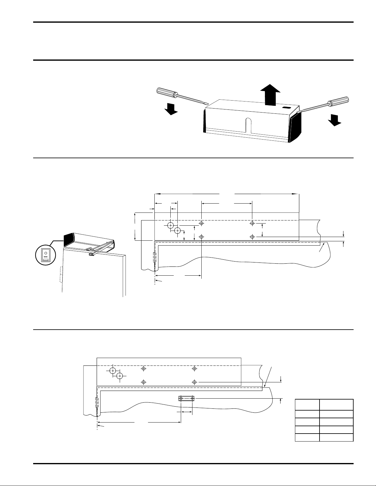
Step #2: Drill and tap four #12 holes with a #12 x 24 tap and mount the mounting plate to the door frame
using four #12 x 24 flat head screws. The conduit end of the mounting plate is to be positioned near the hinge
side of the frame.
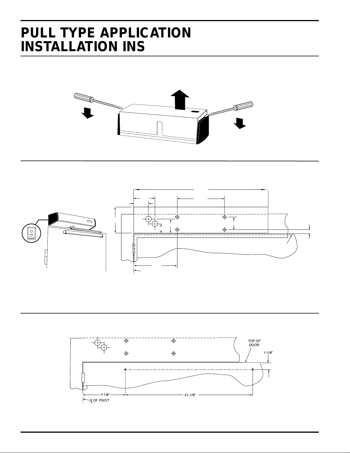
Step #1: Carefully remove the cover using two flat screwdriver as shown.
Operator Housing Removal
PUSH Application Mounting
Plate Hole Locations
7-7/8"
2-3/32"
2-7/16"
3-3/8"
3/4"
FROM TOP
OF FRAME
TOP OF
DOOR
22-7/8"
4-1/2"
7-1/4"
2"
2-1/2"
C OF PIVOT
L
Opening Angle Max. 100°
2651/2652 Shown
PUSH TYPE APPLICATION
INSTALLATION INSTRUCTIONS
Step #3: Drill and tap (two places) door arm foot or slide track holes with a #7 drill. Tap holes 12 x 24.
PUSH Type Arm Application
13-1/16"
1-3/4"
TOP OF
DOOR
DIM. "A"
C OF PIVOT
L
DIM “A” SPINDLE
EXTENSION
1-9/16" ——
1-15/16" 63-0603
2-3/8" 63-0604
3-15/16" 63-0605
6
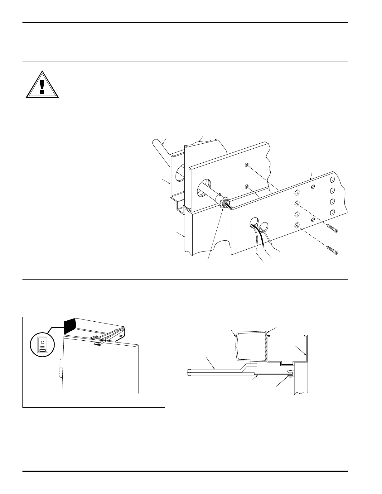
Step #4: Pull conduit and exter nal
component wires through frame and cutout
in mounting plate. Allow at least 10 inches
of exposed wire for electrical connections.
CONDUIT
FRAME
DOOR
WALL
WHITE (+)
BLACK (–)
GREEN (GND)
END OF CONDUIT MUST
NOT PROTRUDE PAST
THE SURFACE
MOUNTING
PLATE
WARNING: Ensure that 115VAC
power is OFF before touching wires.
Step #5: Mount the door operator to the mounting plate with four M8x25 screws and washers provided.
Note: Mount the operator with the power switch end cap toward the door hinge.
MOUNTING
PLATE
DOOR
FRAME
DOOR
OPERATOR
PUSH ARM
EXTENSION ARM
DOOR ARM FOOT
PUSH TYPE APPLICATIONS
INSTALLATION INSTRUCTIONS
7
• Attach the push arm to the door operator spindle
using the longer 8mm bolt and lock washer provided
• Attach the door arm foot with two screws
• Position the door arm foot 90 degrees with the door
in the closed position and tighten with two 4mm
screws
90°
HINGE
DOOR ARM FOOT
DOOR
PUSH TYPE APPLICATION
INSTALLATION INSTRUCTIONS
Step #6: Mount the push arm.
8
Step #1: Carefully remove the cover using two flat screwdriver as shown.
Operator Housing Removal
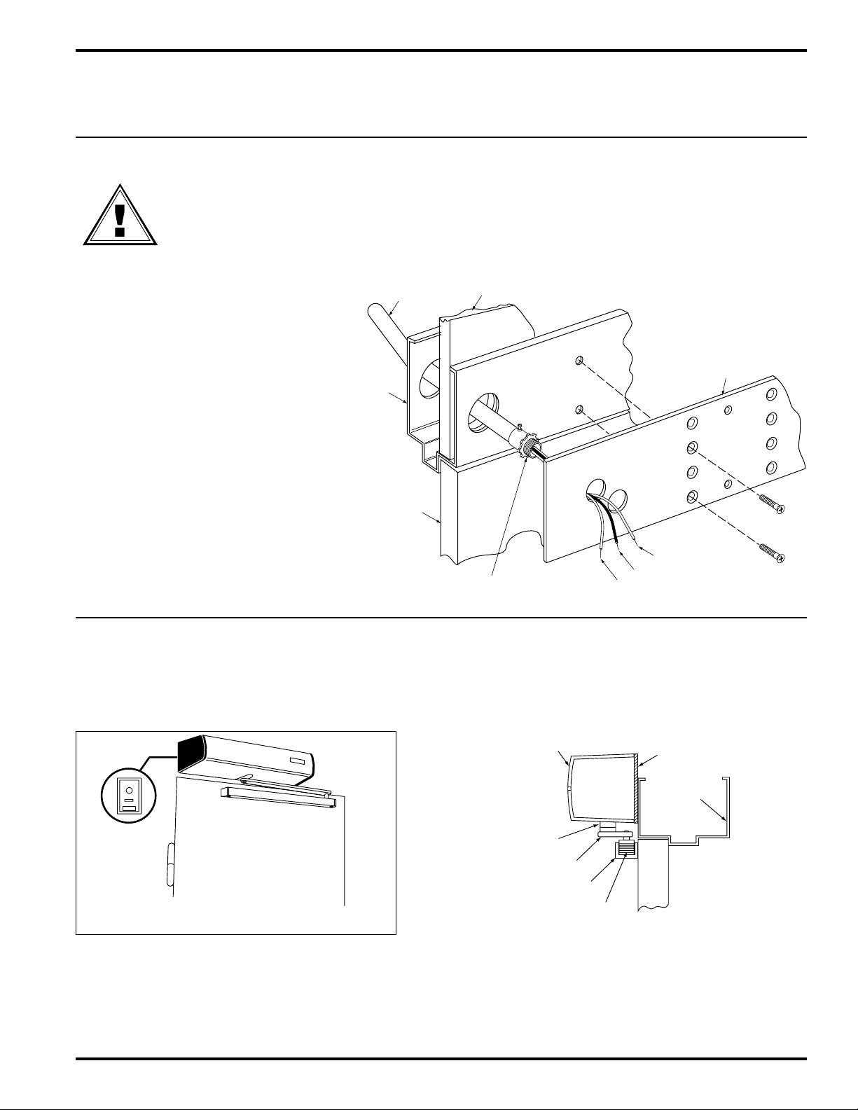
PULL Application Mounting Plate Hole Locations
Opening Angle Max. 100°
2660 Shown
Step #2: Drill and tap four #12 holes with a #12 x 24 tap and mount the mounting plate to the door frame using
four #12 x 24 flat head screws. The conduit end of the mounting plate is to be positioned near the hinge side of the
frame.
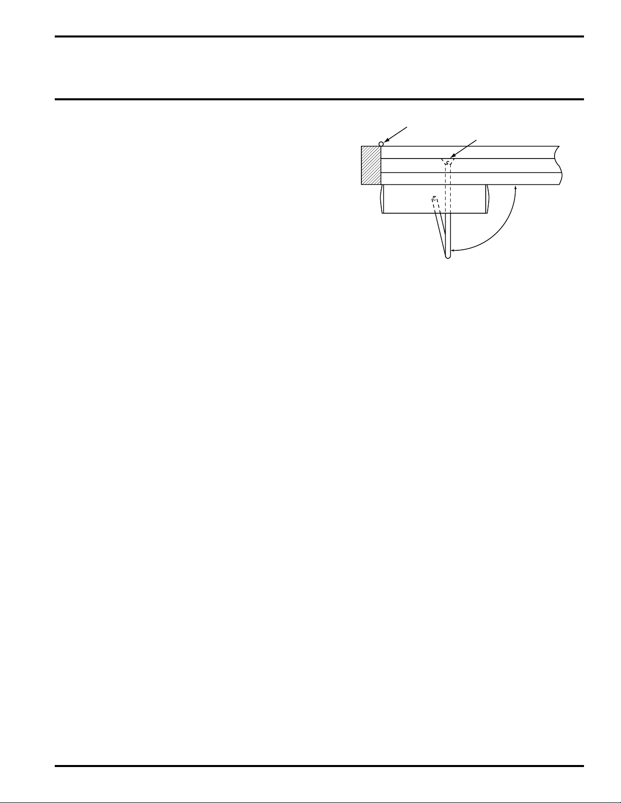
Step #3: Drill and tap (two places) door arm foot or slide track holes with a #7 drill. Tap holes 12 x 24.
PULL Type Arm Application
7-1/8"
21-1/8"
1-1/8"
TOP OF
DOOR
C OF PIVOT
L
PULL TYPE APPLICATION
INSTALLATION INSTRUCTIONS
7-7/8"
2-3/32"
2-7/16"
3-3/8"
3/4"
FROM TOP
OF FRAME
TOP OF
DOOR
22-7/8"
4-1/2"
7-1/4"
2"
2-1/2"
C OF PIVOT
L
9
WARNING: Ensure that 115VAC
power is OFF before touching wires.
Step #4: Pull conduit and exter nal
component wires through frame and
cutout(s) in mounting plate. Allow at
least 10 inches of exposed wire for
electrical connections.
CONDUIT
FRAME
DOOR
WALL
WHITE (+)
BLACK (–)
GREEN (GND)
END OF CONDUIT MUST
NOT PROTRUDE PAST
THE SURFACE
MOUNTING
PLATE
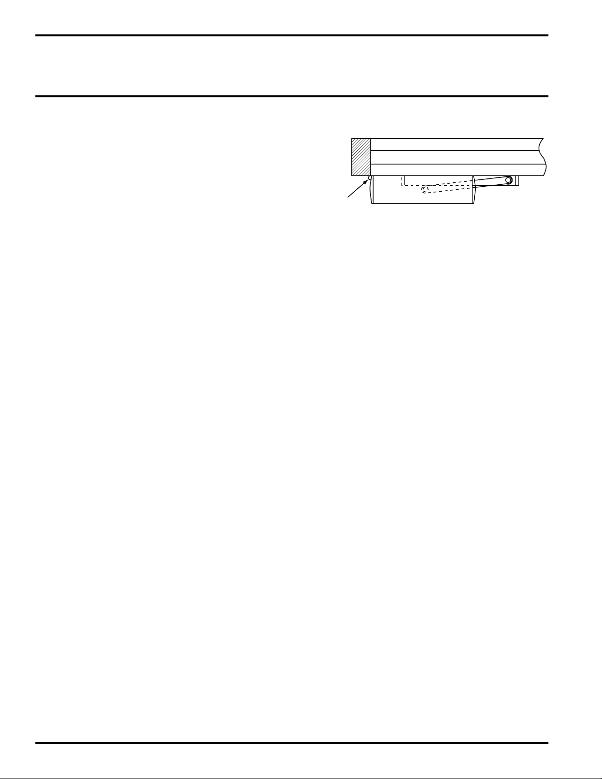
Step #5: Mount the door operator to the mounting plate with four M8x25 screws and washers provided.
Note: Mount the operator with the power switch end cap toward the door hinge.
DOOR
FRAME
MOUNTING
PLATE
DOOR
OPERATOR
PULL ARM
SPACER
(IF REQUIRED)
TRACK
ROLLER
(CAP NOT SHOWN)
PULL TYPE APPLICATION
INSTALLATION INSTRUCTIONS
10
• Attach the slide track with two Phillips screws
provided
• Place door arm roller into track
• Line up key way of door arm to the operator spindle
• Attach the door arm to the operator spindle using the
longer 8mm bolt provided
HINGE
DOOR
PULL TYPE APPLICATION
INSTALLATION INSTRUCTIONS
Step #6: Mount or slide track.
 Loading...