

Page 1
SARGENT®1331 DOOR CLOSER INSTALLATION
Frame
Unreinforced
Door stop
Mortise nut
Drill 3/8" Dia
hole for mortise
nut body
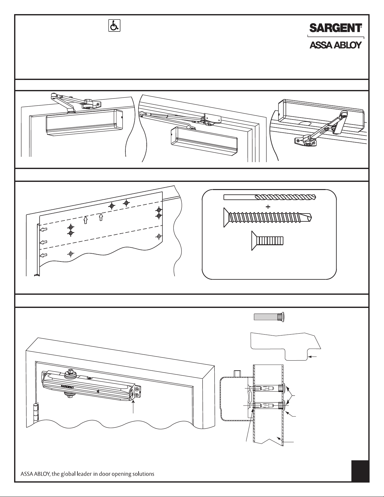
INSTRUCTIONS WITH JUH (HOLD OPEN) ARMS
Strength Adjustable From Size 1 Thru 6
CAUTION: FAILURE TO INSTALL OR ADJUST PROPERLY MAY RESULT IN INJURY OR DAMAGE.
FOR ASSISTANCE, CALL SARGENT AT 1-800-727-5477 or www.sargentlock.com
Choose From 1 of the 3 Applications Below
JH Standard Arm JPH9 Parallel Arm JH Top Jamb Arm
Use Standard & Parallel Full Size Templates Provided
NOTE: With swing clear hinges, use data sheets provided.
* 1/4" Variance allowed for retrofit of existing closers
With fasteners provided, secure closer body to door with
power adjustment away from hinge.
OR
Pre-drill - 3/32” holes
for self tapping screws or #16 drill for
#12-24 tap for machine screws
Using optional mortise nuts when through-bolting
Frame
Door stop
Mortise nut
Power Adjustment
Drill 3/8" dia.
hole for mortise
nut body
Drill 1/4" dia. hole
for screws
Copyright©2008, Sargent Manufacturing Company,anASSAABLOY Group company. All rights
reserved. Reproduction in whole or in part without the express written permission of Sargent
Unreinforced
door
Manufacturing Company is prohibited.
A7742A
1
Page 2
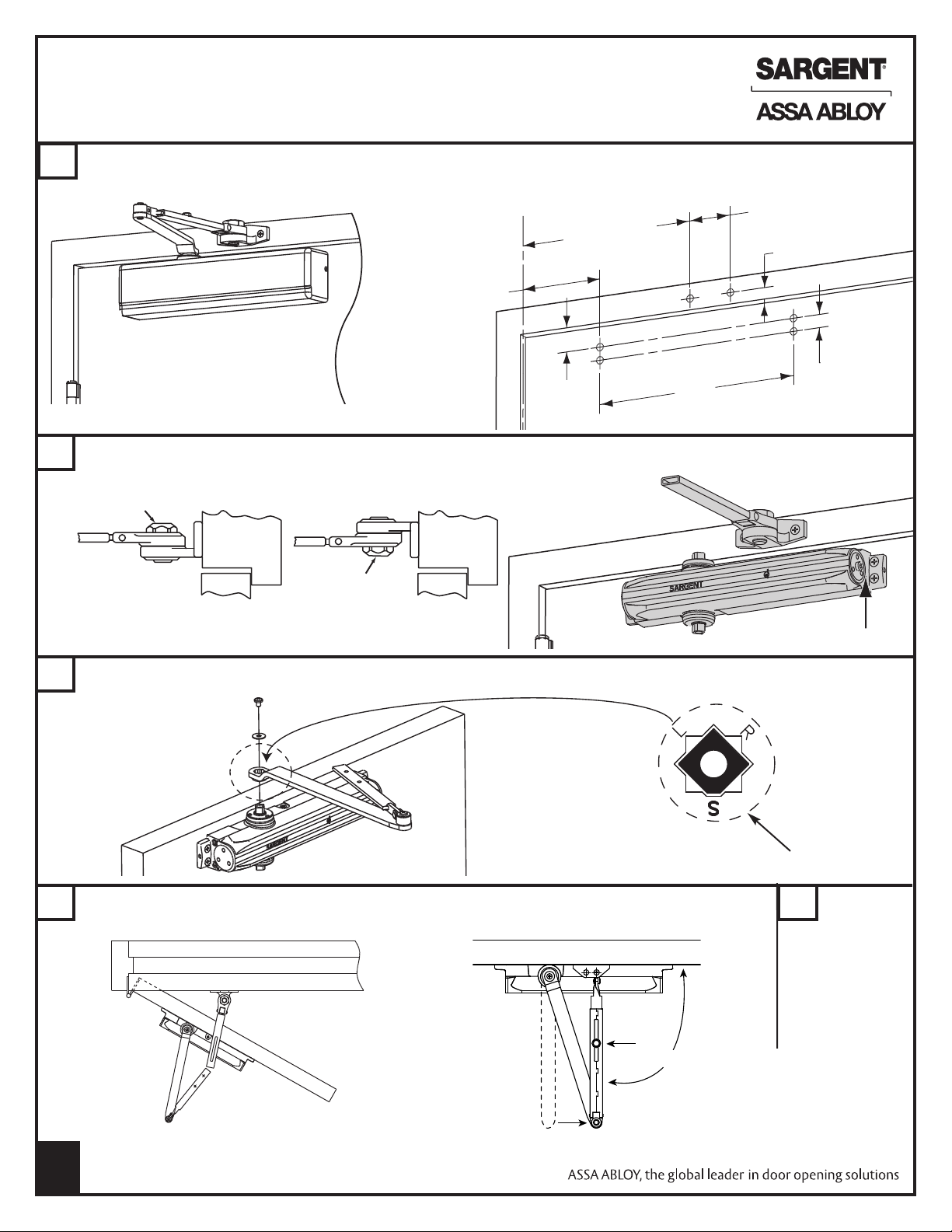
1331 STANDARD APPLICATION JH
-
-
-
-
-
-
-
-
-
-
Frame Frame
Nut faces down
Nut faces up
Left hand
door shown
Right hand
door shown
HOLD OPEN ARM INSTRUCTIONS
Determine maximum degree of door opening required. Use a #16 drill. Drill and tap door and frame for 12-24 machine screws.
1
When using the included self tapping screw, predrill with a 3/32" drill. *Provides maximum power for heavy or drafty doors
2-
1/2"
120° - 12”)
*(
180° - 10-1/8"
*(120° - 6-12")
180° - 4-5/8"
1"
With provided fasteners, install foot to frame and secure closer body to door with power adjustment away from hinge
2
On both right and left hand doors, secure main arm to top spindle with screw and washer provided. Align flat mark as shown
3
1-3/8"
Right hand shown, left hand similar.
12"
3/4"
Power adjustment
Flat mark
Open door and insert foot into main arm. Close door fully, and while pushing arm as shown in picture,
4
tighten arm bolt
Arm
Bolt
90°
Copyright©2008, Sargent Manufacturing Company,anASSAABLOY Group company. All
rights reserved. Reproduction in whole or in part without the express written permissionof
Sargent Manufacturing Company is prohibited.
2 7
A7742A
5
See page 5
for closer
adjustment
and cover
installation.
Page 3
1331 JPH9 PARALLEL HOLD OPEN INSTRUCTIONS
F
rame
Door
IMPORTANT
Nut faces
down for
left hand
and faces
up for right
hand door
Cover
Use 1331-D Drop
bracket if door
rail is too narrow
2-1/2" Min.
1331D
Drop plate used when
top rail is less than 2 1/2"
1
Determine maximum degree of door opening required.
Use a #16 drill. Drill and tap door and frame for 12-24 machine
screws. When using the included self tapping screws, predrill
with a 3/32" drill.
*Provides maximum power for
heavy or drafty doors
Right hand shown, left hand opposite.
With fasteners provided, install foot to frame
2
with nut as shown and closer body to door
with power adjustment toward hinge
Center line
of hinge
3/4"
3-1/2"
1/2"
2-1/2"
12"
Center line
*(120° - 3-3/4")
180° - 1-3/8"
*(120° - 9-1/2")
180° - 7-1/8"
5/8"
1-1/4"
1-7/8"
of hinge
Center line
of hinge
3
Open door and insert foot into main arm. Close door fully, while holding elbow 1-1/4" from door. Tighten arm bolt
4
5
See page
5 for
adjustment
and cover
installation
Left Hand
Door
Drop Plate
Flat
mark
Right Hand
Door
With wrench on bottom
spindle, preload/index by
turning spindle as shown
and secure main arm to top
spindle with flat mark as
indicated at left with screw
and washer
1-1/4"
Arm bolt
Accessory Information
581-1 Blade Stop Spacer Kit
Metal spacer for use on 1/2"
blade stops on aluminum
store fronts
Copyright©2008, Sargent Manufacturing Company,anASSAABLOY Group company. All rights
reserved. Reproduction in whole or in part without the express written permission of Sargent
Manufacturing Company is prohibited.
A7742A
Page 4

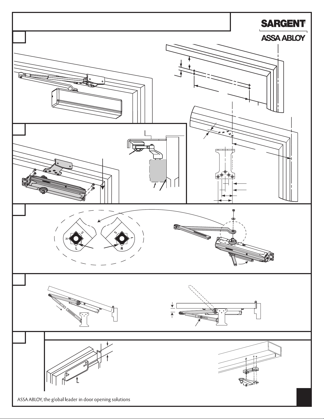
1331 JH TOP JAMB PARALLEL HOLD
Nut faces down
Nut faces up
Right hand
door shown
Left hand
door shown
OPEN INSTRUCTIONS
Determine maximum degree of door opening required. Use a #16 drill. Drill and tap door and frame for
1
12-24 machine screws. When using provided self tapping screws, predrill with a 3/32" drill.
*Provides maximum power for heavy or drafty doors
3/4"
2-1/2"
Right hand door shown, left hand door similar
2
With provided fasteners, install foot to door as shown and closer body to frame with power adjustment away from hinge
Hinge edge
Power Adjustment
12"
*(120° - 12-3/8")
180° - 10-1/8"
Center line
of hinge
*(120° - 6-3/4")
180° - 4-5/8"
1/2"
2-1/4"
3
On both right and left hand doors, secure main arm to spindle with screw and washer provided. Align flat mark as shown
4
Open door and insert foot into main arm. Close door fully, and while pushing arm as shown in picture, tighten arm bolt
Arm
Bolt
Flat mark
Accessories
90°
See page 5 for adjustment and cover installation
5
Copyright©2008, Sargent Manufacturing Company,anASSAABLOY Group company. All
rights reserved. Reproduction in whole or in part without the express written permissionof
Sargent Manufacturing Company is prohibited.
4
A7742A
Page 5

CLOSER ADJUSTMENT AND COVER INSTALLATION
HE 1331 IS FACTORY ADJUSTED FOR MOST APPLICATIONS, HOWEVER,
T
ADDITIONAL ADJUSTMENT MAY BE REQUIRED DUE TO ACTUAL CONDITIONS
MINIMUM RECOMMENDED DOOR CLOSING TIME FOR DOORS OPENED TO 90° IS 6 SECONDS.
5
Use 1/8" hex (Allen) wrench to adjust valves as needed.
SWEEP AND LATCHING SPEEDS:
Turn valves clockwise to slow down or counterclockwise to speed up door movement
BACKCHECK:
To regulate the intensity of backcheck action, turn valve clockwise to increase or counterclockwise to decrease checking
CAUTION: SET VALVE FOR SLIGHT CUSHIONING EFFECT. CLOSER CAN BE DAMAGED IF THE CHECKING ACTION IS
TOO ABRUPT. NEVER USE THE BACKCHECK AS A DOOR STOP. ALWAYS USE A DOOR STOP TO STOP THE DOOR
IF ADJUSTMENTS ARE INEFFECTIVE, CHECK INDEXING AS SHOWN IN STEP 3 AND
CHECK FOR CORRECT TEMPLATING
Sweep (Closing)
Speed
up
Slow
down
Spring power adjustment
1/8" HEX wrench
Latching speed
1/8"
speed range
Backcheck
range
range
CLOSING POWER:
Certain applications may require closing power adjustment:
If the door will not latch properly, increase power by turning
the power adjustment clockwise in full turn increments.
If the door is hard to open, reduce power by turning the power
adjustment counter-clockwise in full turn increments.
COVER INSTALLATION
6
Move insert if needed. Install cover
with two #6- 32 X 5/16" machine
screws as shown.
7
ADJUSTMENT HOLD OPEN ARM
Slight tightening or loosening of hold open nut changes holding
position of door.
NOTE: To protect wall, trim and closer, use a door stop located 5°
beyond hold open positions, but not beyond the max. door opening shown on instructions.
Sweep
Backcheck
Latch
Insert
Use 15/16"
wrench to
adjust nut
Hold
open
nut
Copyright©2008, Sargent Manufacturing Company,anASSAABLOY Group company. All rights
reserved. Reproduction in whole or in part without the express written permission of Sargent
Manufacturing Company is prohibited.
A7742A
5
Page 6

F
rame
Door
IMPORTANT
Nut faces
down for
left hand
and faces
up for right
hand door
Cover
Use 1331-D Drop
bracket if door
rail is too narrow
2-1/2" Min.
1331D
Drop plate used when
top rail is less than 2 1/2"
Copyright©2008, Sargent Manufacturing Company,anASSAABLOY Group company. All
rights reserved. Reproduction in whole or in part without the express written permissionof
Sargent Manufacturing Company is prohibited.
6 3
A7742A
Page 7

-
-
-
-
-
-
-
-
-
-
Copyright©2008, Sargent Manufacturing Company,anASSAABLOY Group company. All rights
reserved. Reproduction in whole or in part without the express written permission of Sargent
Manufacturing Company is prohibited.
A7742A
Page 8

-
-
-
-
-
-
Frame
Unreinforced
Door stop
Mortise nut
Drill 3/8" Dia
hole for mortise
nut body
Copyright©2008, Sargent Manufacturing Company,anASSAABLOY Group company. All
rights reserved. Reproduction in whole or in part without the express written permissionof
Sargent Manufacturing Company is prohibited.
8
A7742A
 Loading...