

Page 1
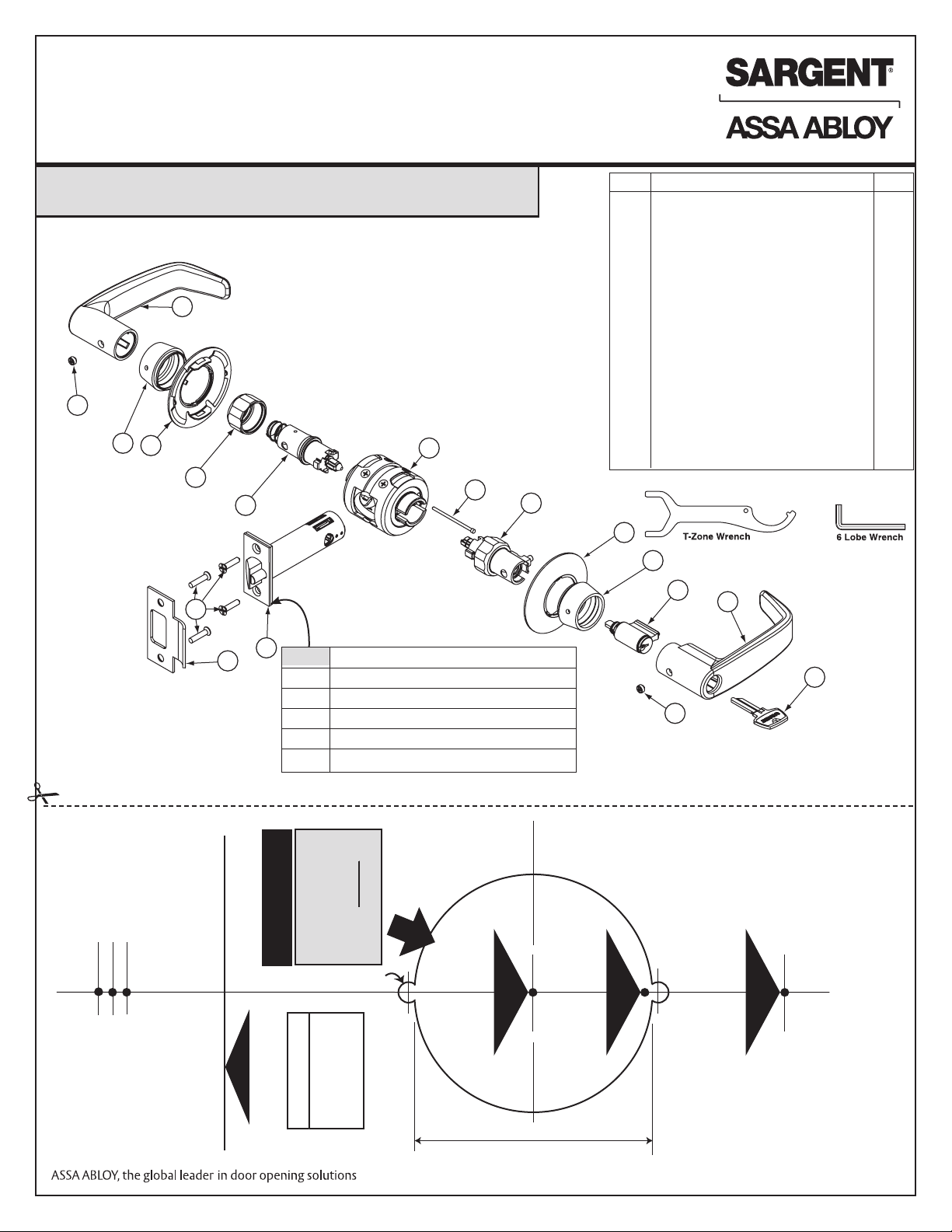
INSTALLATION INSTRUCTIONS FOR
Mark for 1" hole
at center of
door thickness
FOLD HERE
IMPORTANT
Place fold on
HIGH EDGE
of beveled door
Mark center for
2-1/8" crossbore
hole at correct
backset
IMPORTANT
2"
1-3/4"
2-3/4" (70 mm) BACKSET
3-3/4" (95 mm) BACKSET
5" (127 mm) BACKSET
11 Line U.S. Patent No. 6,626,018
FOR ASSISTANCE, CONTACT SARGENT AT 800-727-5477 or www.sargentlock.com
To view helpful video installation tips, scan the Microsoft® Tags with
your mobile phone. Download the free mobile app at http://gettag.mobi.
1
2
4
3
5
14
6
13
15
Code stamp
location
Code Latchbolt Functions
A 15
B 04, 05, 13, 15-3, 16, 17, 30, 37, 38
C 65
D 44, 50, 54
K 24
7
8
Item Description Qty.
1 Inside Lever 1
2 6 Lobe Security Set Screw, 2
1/4-28 x 11/64" 2
3 Rose 2
4 Rosette 2
5 Inner Collar 1
6 Inner Sleeve 1
7 Bearing Assembly 1
8 Aligning Pin 1
9 Outer Sleeve (with captive Collar) 1
10 Cylinder 1
11 Outside Lever 2
12 Keys 1
13 Latch Assembly 4
14 Screw, Flat Hd, #8-32 x 3/4" 1
15 Strike (800 shown)
9
3
4
10
11
12
2
2-1/4" (57mm)
2" (51mm)
1-3/4" 44mm)
Mark for
1" hole (25mm)
at center of
door thickness
LATCHBOLTS ARE NOT INTERCHANGEABLE.
IMPORTANT
Mark center for
2-1/8" crossbore
hole at correct
backset
2 x 5/32" (4 mm) Dia
2-3/4" (70 mm)
HIGH EDGE
Place fold on
IMPORTANT
FOLD HERE
of beveled door
2-1/8" (54 mm) Diameter
NOTE– CONSULT FACTORY FOR
CORRECT TEMPLATE INFORMATION
FOR 11G93, 11G94 AND 11G94-2
FUNCTIONS
BACKSET
BACKSET
3-3/4" (95 mm)
5" (127 mm) BACKSET
Copyright © 2013 SARGENT Manufacturing. All rights
reserved. Reproduction in whole or in part without
the express written permission of SARGENT
Manufacturing is prohibited.
A7469K
Page 2
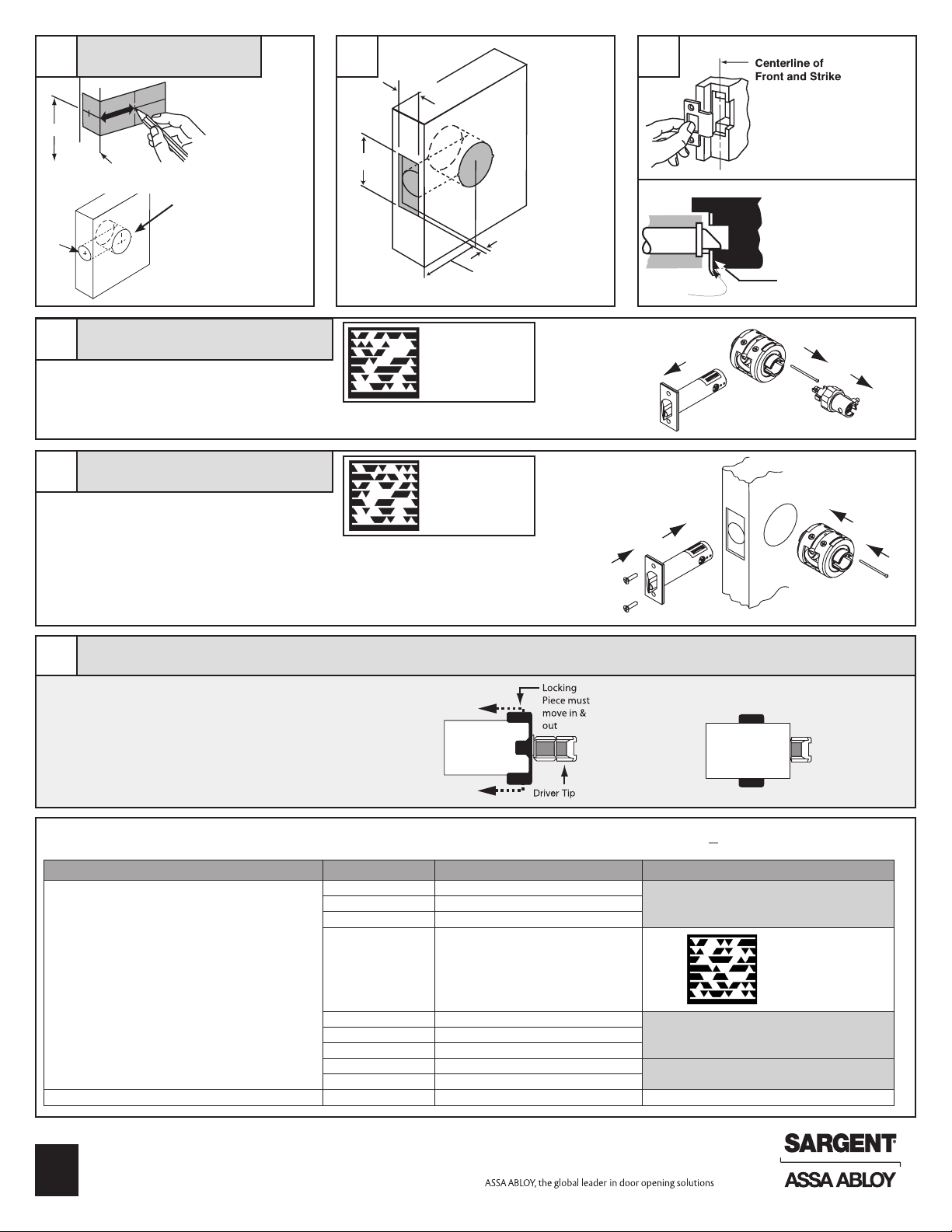
Door Preparation
Outside
Sleeve
"Spring loaded"
1
38"
• Fold template on
door and mark
hole centers
2 3
1-1/8"
•
Mark centerline on jamb
•
Mark outline of strike
Finished
floor
1"
4
5
High edge of
beveled door
2-1/8" Hole
• Bore 2-1/8"
• Bore 1" hole
Lock Disassembly
1. Unthread collar and remove OUTSIDE sleeve
2. Remove aligning pin from bearing assembly
3. Separate latch from bearing assembly
Latchset Installation
Hold door open with door stop
1. Insert bearing assembly
2. Insert latch assembly
3. Insert aligning pin from secure side (outside)
of door
4. Install latch plate screws. Do not tighten
completely until lock installation is finished
2-1/4"
• Cut rectangular front recess
Scan to see a video of
this installation step.
Scan to see a video of
this installation step.
5/32" DEEP
RECESS
DESIRED BACKSET
Inside
•
Cut recess for latch bolt
•
Install strike; secure with
two screws
IMPORTANT
Guardbolt stops on strike
STRIKE
3
INSIDE
Inside
2
4
when door is closed
GUARDBOLT
2
Outside
1
OUTSIDE
Outside
1
3
Function Specific Instructions - Sleeve Assembly
6
IMPORTANT: Sleeves with colored driver tips require that the slotted cam be
rotated allowing the spring loaded locking piece to move freely in and out of
the outside sleeve
Driver Tips with red markings must match up before assembling lock
PLEASE NOTE — Some driver tips have two color markings for function
identification
11G54 - green 11U65 - blue
11G24 - yellow 11G05 - only red
Outside
Sleeve
See Specific Instructions Per Function. Identify Function On Box (Example: 11G05)
For functions not shown proceed to step 7
Outside Sleeve Function Number Function Description Inside Sleeve
04 Storeroom/Closet
16 Classroom Security/Apartment
17 Utility/Asylum
Align driver tips matching the painted sections
24 Entry
See A7608B 50 Hotel/Motel See A7608B
65 Privacy/Bathroom
38 Classroom Security
54 Dormitory
Note: Outside sleeve has collar
attached
Outside
Sleeve
position
Follow Step 705 Entrance/Ofce
Scan to see a video of
this installation step.
Follow Step 744 Service Station
Follow Step 7
Copyright © 2013 SARGENT Manufacturing. All rights reserved. Reproduction in whole or in
part without the express written permission of SARGENT Manufacturing is prohibited.
2
A7469K
Page 3

Sleeve Installation
7
1. With driver tips aligned, insert outside
sleeve first. Dimple must face door edge
2. Thread outside collar by hand.
Tighten to bearing assembly with wrench
3. Insert inside sleeve. Dimple must face door edge
4. Thread inside collar by hand. Tighten to bearing
assembly with wrench
Caution: If excessive wrench
torque is required, stop and
check alignment of driver tips
Cam Orientation
8
1. Lock lever by button if applicable
2. Turn slotted cam until lever catch button can
be depressed
Scan to see a video of
this installation step.
Scan to see a video of
this installation step.
Inside
4
3
2
DIMPLE
1
CAM
NOTE: Dark colored cams on the inside designate for
use with standard cylinders. Silver colored cams on the
inside designate for use iwth I/C & R/C cylinders.
DIMPLE
Outside
Correct Cam Orientation for Standard Cylinder
45º
ANGLE
Rose Installation
9
1. Slide rose over sleeves aligning tabs on rose with slots
on bearing assembly
2. Hand tighten rosettes to door surface
LEVER CATCH SLOT
LEVER CATCH BUTTON
CYLINDER TAIL PIECE SLOT
Caution: If excessive wrench
torque is required, stop and
check for cross-threading
Note: Rosettes must be tightened simultaneously to ensure
proper centering of lock on door.
Scan to see a video of
this installation step.
Correct Cam Orientation for IC/RC Cylinders
45º
ANGLE
(See also A7471 instructions)
LEVER CATCH SLOT
LEVER CATCH BUTTON
CYLINDER TAIL PIECE SLOT
4
Inside
Slots for tabs on rose
Rosette
b
2 Rose
(within sleeve)
Copyright © 2013 SARGENT Manufacturing.
All rights reserved. Reproduction in whole or
in part without the express written permission
of SARGENT Manufacturing is prohibited.
A7469K
3
Rosette
Outside
3
Page 4

Function Specific Directions - Lever Installation
For functions not shown proceed to step 10
Inside Sleeve Function Function Description Outside Sleeve
05 Entrance/Ofce
Lock lever by button
Rotate cam until lever catch button can be
depressed, holding cam in rotated position
24 Entry
44 Service Station
65 Privacy/Bathroom
04 Storeroom/Closet
17 Utility/Asylum
16 Classroom Security/ Apartment Rotate cam until lever catch button can be depressed
30 Communicating
Rotate cam until lever catch button
can be depressed, holding cam in
rotated position
Rotate cam counterclockwise until it stops. Then rotate back 45° until
lever catch button can be depressed.
Scan to see a
video of this
installation step.
Rotate cam counterclockwise until it stops.
Lock lever by button 54 Dormitory
See A7608B 50 Hotel/Motel See A7608B
Lever Installation
10
1. For conventional cylinder, place cylinder into lever. Insert
key and turn 45° CLOCKWISE to align cylinder tailpiece
with deep slot in cam (see slotted cam illustration in step
8). For removable or interchangeable core, see separate
instruction sheet (A7471).
2. Install outside lever. Push on until lever catch engages
Note: If outside lever won't secure in place, rotate key clockwise until lever catch is released.
3. Secure with 6 lobe security set screw until flush with
lever surface
4. Install inside lever. On 17 and 30 function, push on until
lever catch engages.
5. Secure with 6 lobe security set screw until flush with
lever surface
6. Complete tightening of two latchbolt screws
7. Check operation of levers and latchbolt before closing door
38 Classroom Security
Scan to see a video of
this installation step.
Rotate cam counterclockwise until
it stops. Then rotate back 45° until
lever catch button can be depressed.
Rotate cam counterclockwise until it stops. Then rotate back 45° until
lever catch button can be depressed.
Inside
Scan to see a
video of this
installation step.
Outside
11G38 Classroom Security Function
11
Function Description: Inside lever
is always unlocked. Inside key locks/
unlocks outside lever. When inside key
locks outside lever, outside key retracts
the latchbolt but cannot unlock the
outside lever.
Cylinder Removal (Conventional)
12
1. Remove 6 lobe security set screw
2. Insert key and rotate 45° clockwise to release lever catch
3. Depress lever catch and remove lever
Please Note: Removable and interchangeable core cylinders do not require
removing the lever to install. See separate instruction sheet (A7471).
Copyright © 2013 SARGENT Manufacturing. All rights reserved. Reproduction in whole or in
part without the express written permission of SARGENT Manufacturing is prohibited.
4
A7469K
Inside rose is marked with
“Lock” and direction arrows
to indicate locking direction
INSIDE:
Rotate key CLOCKWISE TO LOCK.
Rotate key COUNTER-CLOCKWISE
TO UNLOCK
Lever
catch
Note: If outside lever remains locked,
rotate key on inside lever 360 degrees
counterclockwise, and then rotate key
on outside lever 360 degrees clockwise.
OUTSIDE:
Rotate key COUNTER
CLOCKWISE TO LOCK.
Rotate key
CLOCKWISE TO UNLOCK.
Inside
13
Outside
11U65 Outside Lever
Removal
1. Remove 6 lobe security set screw
2. Lock outside lever by pushing in button on
inside lever.
3. Rotate slot on outside lever with flat blade screwdriver
45° to release lever catch and hold in place
4. Depress lever catch and remove lever
 Loading...