

Page 1
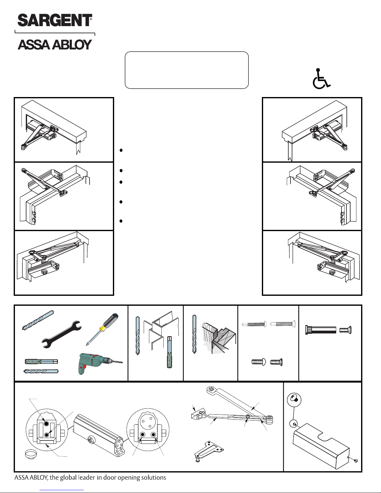
Installation Instructions
80-9311-0011-021 Rev 2
Non Hold Open Models
Adjustable
(Sizes 1 thru 6)
1130 Series
Non Handed Door Closer
Regular Arm
Installation
See Page 2
Right Hand Door - RH
Left Hand Reverse - LHR
Top Jamb
Installation
See Page 5
Left Hand Door - LH
Right Hand Reverse - RHR
An Incorrectly installed or improperly adjusted
door closer can cause property damage or
personal injury. These installation instructions
should be followed to avoid the possibility of
misapplication or misadjustment.
CAUTION
CAUTION
Doors should be hung on ball bearing or
anti-friction hinges.
A separate door stop is recommended.
Door and frame must be properly
reinforced.
Adjust closing time speed between 3 and 7
seconds from 90° to 0°.
These door closers should NOT be
installed on the exposed side (weather
side) of exterior doors.
Regular Arm
Installation
See Page 2
Top Jamb
Installation
See Page 5
Right Hand Door - RH
Left Hand Reverse - LHR
1131
Left Hand Door - LH
Right Hand Reverse - RHR
Parallel Arm
Installation
See Pages
Left Hand Door - LH
Right Hand Reverse - RHR
Spring Power Adjustment
Screw 1131 Series
3 & 4
Standard Components
"BC" Valve
Closer Body
1-6
Closer
Size
Pinion Cap
Stamp
"L"Valve
#7
Metal Wood
1/4-20
3/16"
Regular Arm/Top
Jamb Shoe
Connecting Rod
Soffit Plate
"S"Valve
Copyright © 2016, Sargent Manufacturing Company, an ASSA ABLOY Group company, All rights reserved. Reproduction
in whole or in part without the express written permission of Sargent Manufacturing Company is prohibited.
RU Soffit Plate
Used with Parallel
Arm Closers Only
Parallel Arm
Installation
See Pages
Self Drilling Screws
Wood and Metal
For Wood drill 3/16 hole
Machine Screws
#7 Drill, 1/4-20 Tap
Arm Assembly
Main Arm
Forearm
Screw
Arm Slide
3 & 4
Right Hand Door - RH
Left Hand Reverse - LHR
(Optional)
Sleeve Nut and Bolt
Drill 9/32 thru from Closer Side
3/8 Drill other side
Optional Components
Co
ver
A7674C
Page 2
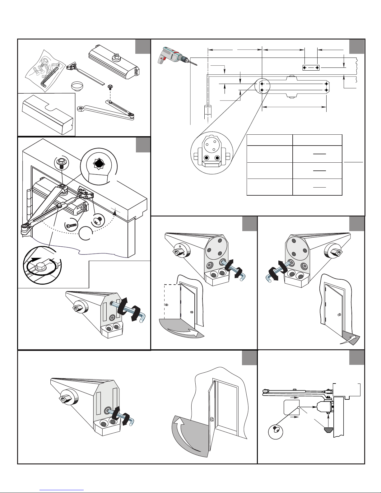
1130 Series
Non Hold Open Door Closers — Regular Arm
80-9311-0011-021 Rev 2
Parts
Cover
Optional
1
A
1-1/4
(32)
3/4
(19)
Right Hand Shown
Opening
6
(152)
9-1/16
(230)
Dimension "A"
3
L
D
L
R
Y
Z
S
C
A
B
Sweep
90°
E
S
To 100°
101° to 120°
121° to 180°
*
Door/Wall/Hardware/Jamb
*
conditions permitting
4
Latch
7
(178)
6
(152)
3-1/2
(89)
1-3/4
(44)
3
2
7/8
(22)
Inches
(mm)
5
F
1131 Spring
Power Adjust
(If Necessary)
Backcheck
G
P
BC
Stronger
A
Stronger
+
Weaker
-
+
Slower
S
L
-
Faster
+
Faster
+
Slower
-
Pinion Cap
6
or Optional Cover
L
S
7
or
Caution:
Don't completely
close valve
Weaker
(2)
-
— 2 —
A7674C
Page 3

1130 Series
Non Hold Open Door Closers — Parallel Arm
80-9311-0011-021 Rev 2
Parts
Door
Opening
To 100°
101° to 130°
131° to 180°
*
Door/Wall/Hardware/Jamb
*
conditions permitting
A
9-1/4
(235)
7-3/4
(197)
5-3/4
(146)
Co
ver
Optional
B
7-5/8
(194)
6-1/8
(156)
4-1/8
(105)
1
Right Hand Shown
Inches
(mm)
Top of
Door
7/16
(11)
2-3/4
(70)
9-1/16
(230)
2
(50)
3/8
(10)
Frame
3/4
(19)
A
1/2
(13)
B
3-1/4
(83)
2
C
L
Close Valves
Latch
3
Sweep
Slower
L
S
-
Slower
-
L
S
4
Remove Arm
from Spindle
Place Arm on
Spindle
R
o
5
t
a
t
e
See Step 6 on Page 4
— 3 —
A7674C
Page 4

1130 Series
Non Hold Open Door Closers — Parallel Arm
80-9311-0011-021 Rev 2
Right Hand
Door
or
Left Hand
Door
Flat
Arm Screw
L
R
S
Z
Y
B
Y
Z
S
R
6
Open Valves
7
Assemble Arm
8
L
A
Flat
Caution:
Do Not Back
Valve Out
Completely
Spring Power
9
Adjust 1131
(If necessary)
10
Sweep
11
1-1/2
(38)
Latch
Faster
+
Slower
-
Slower
S
Stronger
Weaker
Stronger
BC
Weaker
+
-
13
+
-
Pinion Cap
or Optional Cover
(2)
PA
12
L
S
Backcheck
L
-
Faster
+
14
or
Caution:
Don't completely
close valve
— 4 —
A7674C
Page 5

1130 Series
Parts
Cover
Optional
A
B
Z
S
R
L
C
E
90°
Y
D
Non Hold Open Door Closers — Top Jamb Arm
80-9311-0011-021 Rev 2
1
Inches
(mm)
9-1/16
(230)
1-1/2
(38)
1-3/4
(44)
Door/Wall/Hardware/Jamb
*
conditions permitting
3/4
(19)
6
(152)
Right Hand Shown
A
1/2
(13)
3
Opening
To 100°
101° to 120°
121° to 180°
*
Sweep
Dimension "A"
7-1/2
(191)
6
(152)
3-1/2
(89)
A longer connecting
rod is required
for reveals greater
than 3" (76)
4
Latch
Reveal
C
L
2
Top of
Door
5
G
P
Backcheck
Stronger
A
+
Weaker
-
F
1131 Spring
Power Adjust
(If Necessary)
Stronger
BC
+
Slower
S
L
-
Faster
+
Faster
Pinion Cap
6
or Optional Cover
+
Slower
-
(2)
L
S
7
or
Caution:
Don't completely
close valve
Weaker
-
— 5 —
A7674C
Page 6

1130 Series Adjustments Page
For installation assistance, contact SARGENT at 800-810-WIRE (9473)
Copyright © 2016, Sargent Manufacturing Company, an ASSA ABLOY Group company. All rights reserved.
Reproduction in whole or in part without the express written permission of Sargent Manufacturing Company is prohibited.
80-9311-0011-021 Rev 2
Sweep
(Use 1/8" Hex Wrench for these Adjustments)
Slower
S
L
-
Faster
+
Spring Power
Adjust 1131
PA
Faster
+
Slower
Latch
L
-
Stronger
+
Weaker
-
Backcheck
S
Adjustment Chart
TYPE
OF
DOOR
INST.
Regular Arm
Top Jamb
Parallel Arm
INTERIOR
1131
Regular Arm
Top Jamb
Parallel Arm
EXTERIOR
Stronger
BC
30 FULL (360°) TURNS MAXIMUM AVAILABLE
*
+
Weaker
-
*
3/16 POWER
FULL 360° TURNS OF
70°
10°
CLOSED
Number of Turns Required
MAXIMUM DOOR SIZE
34”
(0.85M)
2
5
ADJUSTMENT WRENCH
= 8 Turns As Shipped
36”
(0.90M)
3
3
40”
(1.00M)
4
5
5
8
6
8
8
11
44”
(1.10M)
10
11
11
16
48”
(1.20M)
12
14
14
19
(Use 3/16" Hex Wrench for this Adjustment)
To identify your model:
Size
Code
1-6
BE
Date
Code
1- 6=1131
Arm Placement in Shoe
— 6 —
7-1/2 % Stronger
+
or
or
7-1/2 % Weaker
-
A7674C
 Loading...