

Page 1
INSTALLATION INSTRUCTIONS FOR
38" fr
Finished Floor
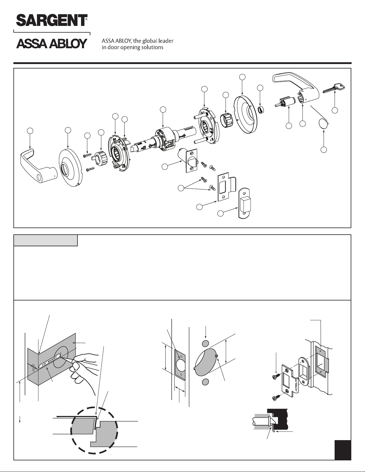
10 Line Lever Lock
For installation assistance, contact SARGENT at 800-727-5477
www.sargentlock.com
(Patents Pending)
Tools
#2 Phillips screwdriver
Push pin (provided)
7/16” drill bit
1/8” drill bit
2-1/8” bore
1” bore
1
Parts
1. Inside lever
2. Scalp (2)
3. Screws – mounting plate
(2) #6 x 3/4” self-tapping
4. Spacer bushing (2)
* Used with 68 Function only
2
Door Preparation
5
6
4
3
Inside of Door
5. Inside rose assembly
6. Screws – through-bolt
(2) #10-32 x 1-1/4”
7. Lockbody
8. Outside rose assembly
9. Cylinder spacer
2
8
4
7
Outside of Door
(secured side)
14
15
16
17
9
11
10
13
10. Cylinder
11. Outside lever
12. Key
13. Push pin
14. Latch
15. Screws – latch & strike
(4) #8-32 x 3/4”
16. Strike
17. Strike box
12
• All doors should be properly reinforced for lock support. If support is not provided, contact door manufacturer.
• For all metal door preparations use template A4375, EXCEPT for functions 10G70 or 10G71 which uses template 4409
(provided), or functions 10U93, 10U94 and 10U94-2 which require template A4375.
• For all wood door preparations use template A6719, EXCEPT for functions 10G70 & 10G71 which uses template 4409
(provided), or functions 10U93, 10U94 and 10U94-2 which requires template A4375.
• Template information is available on our website, www@sargentlock.com.
• Mark and Drill Holes
IMPORTANT:
Fold template onto high
edge of door bevel
• Final Door Prep • Frame Prep for Strike
1"
(25mm)
7/16" (11mm) hole
Centerline of
latch front and
strike
hole
Template
2-1/4"
2-1/8"
(54mm)
hole
Screws (2)
#8-32 x 3/4"
(57mm)
Door
Bevel
FRAME
5/32"
(4mm)
1-1/8"
(29mm)
Strike
om
Backset
must match lock
(2-3/8" or 2-3/4")
DOOR
IMPORTANT: Deadlocking latch must
stop on strike when door is closed
© SARGENT Manufacturing Company A7133J
1
Page 2
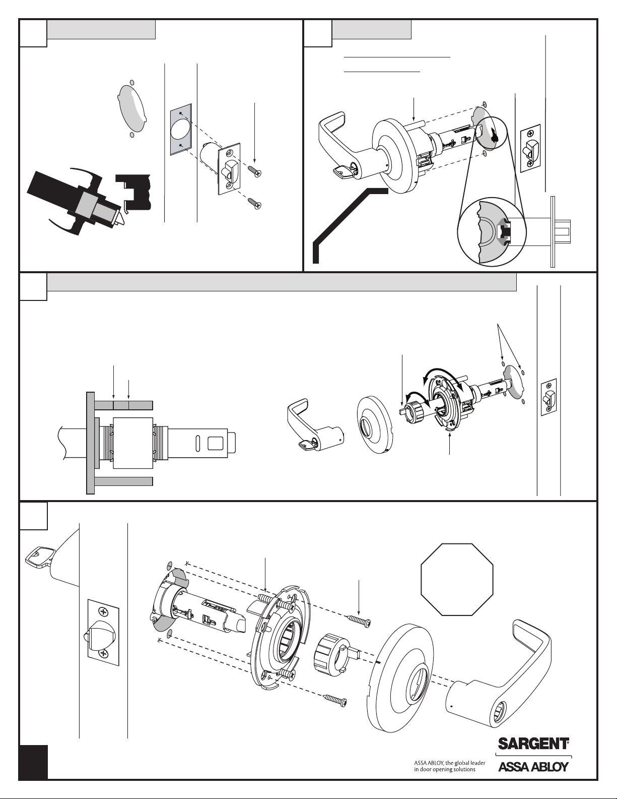
Door
frame
bladed screwdriver at notch
1
Preset thrubolt locations –
for different locations see
instructions to the right
Outside
of Door
Install loosely;
tighten after step #3
Screws (2)
#8-32 x 3/4”
Please note: Doors without a beveled edge need to be
adjusted to center the latch - adjust per step 2A.
2
Through-bolt and door thickness adjustment other than preset
2A
• Remove – outside lever (usually keyed), scalp and spacer bushing
• Rotate – mounting plate to either align with through-bolt holes in door
or adjust for proper door thicknesses (see markings on through-bolt)
• Reinstall – spacer bushing (to align with back of lever), scalp and lever
1-3/4" thick door
2" thick door
Preset Lock Latch Installation
• Through-bolt Location – 12 and 6 o’clock
• Door Thickness – 1-3/4” thick
• See Step 2A for other door conditions
Outside
of Door
Through-bolt
holes
Spacer bushing
3
Screws (2)
10-32 x 1-1/4"
Screws (2)
#6 x 3/4"
Scalp to be removed with flat
Mounting plate
with through-bolts
Test
for proper
operation
before
closing
door
2
A7133J © SARGENT Manufacturing Company
Page 3

Lever and Cylinder Removal
Rotate key 45ϒ
and hold
Remove/Reuse
6 Pin Tailpiece
Plastic Core
Construction
Core
7-pin –
in box
6-pin –
in core
Keyed
Keyed
Cylinder
Washers
(only 30-prefix)
Cylinder
Outside
lever
Key
Cylinder
spacer
4
7-pin –
in box
Keyed
Cylinder
Remove/Reuse
6 Pin Tailpiece
Plastic Core
7-pin –
in box
6-pin –
in core
Keyed
Keyed
Cylinder
7-pin –
in box
Keyed
Cylinder
Standard Cylinder
Rotate key 45ϒ
and hold
Depress lever retainer
with push pin tool
Standard Cylinder Installation
IMPORTANT:
Before cylinder installation 10G16, 10G30,
10G37, 10G38 and 10G54 functions
lock, must be timed/preset by rotating
cam (within the the lever support tube)
completely counterclockwise.
Interchangeable and Removable Core Cylinder
• Remove cylinder and tailpiece, using
control key (stamped “C”)
• Insert Phillips #2 screw driver into
C
Control key*
cylinder opening making contact with
lever retainer.
• Pull lever retainer horizontally towards
door hinge and remove lever.
*Note- 1 Bitted cylinders utilize a control
key cut 113511
Lever retainer
Interchangeable or Removable Core Installation
• Remove construction core
or plastic core
If keyed – use Control Key
(stamped “C”) rotate 15
degrees and pull
C
• IMPORTANT:
Remove tailpiece from construction
core and insert into new cylinder
Remove
Construction
Core
Remove/Reuse
6 Pin Tailpiece
Plastic Core
Construction
Core
7-pin –
in box
Install
New/Final
Cylinder
Cylinder
6-pin –
in core
Keyed
Keyed
Cylinder
Correct key orientation
during assembly
• Install Cylinder
Insert cylinder with control key (stamped “C”)
into lever; rotate 15 degrees and remove key
C
© SARGENT Manufacturing Company A7133J
New Cylinder
3
Page 4

Remove 10G13
• Remove inside (non-rigid) lever with standard
push pin
• Insert long push pin into inside lockbody tube
and push to release spring loaded lever catch
plug assembly for the outside lever
• Remove the outside lever with lever catch plug
assembly attached
Install 10G70 & 10G71
• Power Required: 24Volt DC, .25 amps,
wiring information provided
• Wires must be protected from
abrasion
• Important- See correct door template
4409 provided or on the
website at www@sargentlock.com.
Function Description:
10G70 Fail Secure
Power OFF unlocks outside lever
Power ON locks outside lever
Key retracts latch at all times
10G71 Fail Secure
Power ON unlocks outside lever
Power OFF locks outside lever
Key retracts latch at all times
Install 10U94/10U94-2
Install 10U93
Screw
1/4 x 20
Cup
washer
2 holes to align with
2 tabs on rose
Screws (2) #6 x 3/4"
Rose
Scalp to be removed
with flat bladed screwdriver
4
A7133J © SARGENT Manufacturing Company
Tab
Screws (2)
#8-32 x 3/4"
2 holes to align with
2 tabs on rose
Screws (2) 10-32 x 1-1/4"
Screws (2) #6 x 3/4"
Rose
Scalp to be removed
with flat bladed screwdriver
 Loading...