

Page 1
INSTALLATION MANUAL
Color CCD Camera
THIS INSTALLATION SHOULD BE MADE BY A QUALIFIED
SERVICE PERSON AND SHOULD CONFORM TO ALL LOCAL
CODES.
Please read this manual before installing and using this unit, and always follow the instructions
in it for proper use. Please also read the separate INSTRUCTION MANUAL before using the unit
for proper use.
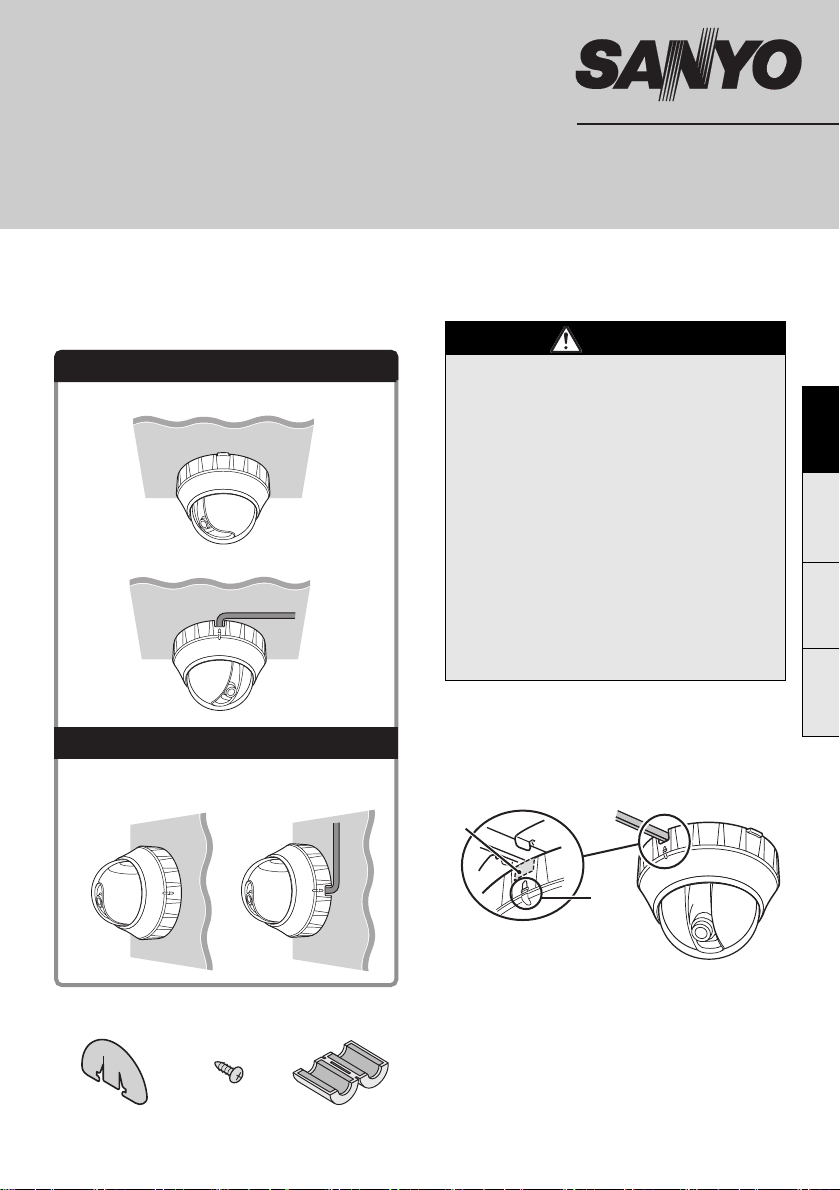
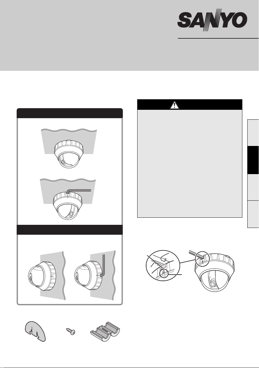
This unit can be installed on the ceiling or wall.
Ceiling Installed (see page 1)
(In-ceiling routing)
(Surface routing)
• Be careful when opening holes for installing
the unit. Work with the power and video
cables pulled out for easy installation.
• Make sure to properly perform waterproofing
for the ceiling or wall where you are installing
the unit.
• Make sure that the surface in the installation
location has no unevenness and is strong
enough to bear the total weight of the unit.
• Install this unit in an environment where the
temperature range stays between -10°C
and +40°C (no condensation allowed).
• As a precaution against static electricity
damage, touch a nearby metal object (door
knob, etc.) to dissipate static electricity in
your body before touching this unit.
VCC-P9575P
Important
EnglishFrançaisDeutsch中文简体
Wall Installed (see page 3)
(In-wall routing) (Surface routing)
b Accessories
1 Cover sheet 2 Screw
3 Clamping
core x2
b When routing the cables on ceiling or wall
surfaces:
Twist off the knockout piece (B) above the rib
mark (A) with a pair of pliers, etc. and pass the
connection cables through the hole.
B
A
b Replacement timing of major parts
If the unit is used continuously, parts will become worn
and deteriorated depending on the environment of use.
It is recommended that parts be replaced
approximately every 2 years (approximately 1,200,000
times) in order to maintain unit performance.
• Motor, cables used in mechanical parts, gears, etc.
Page 2

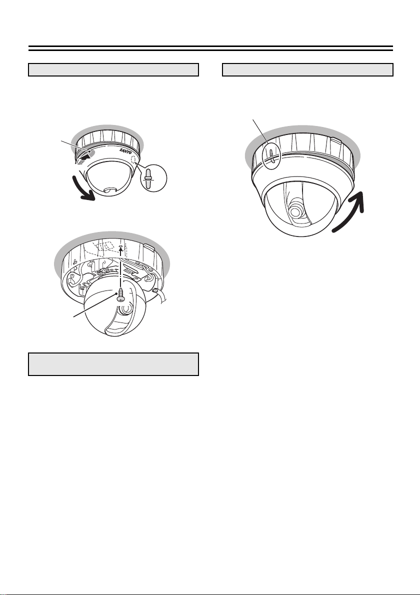
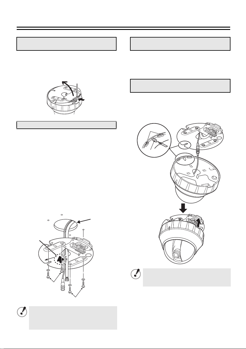
Installing on the Ceiling
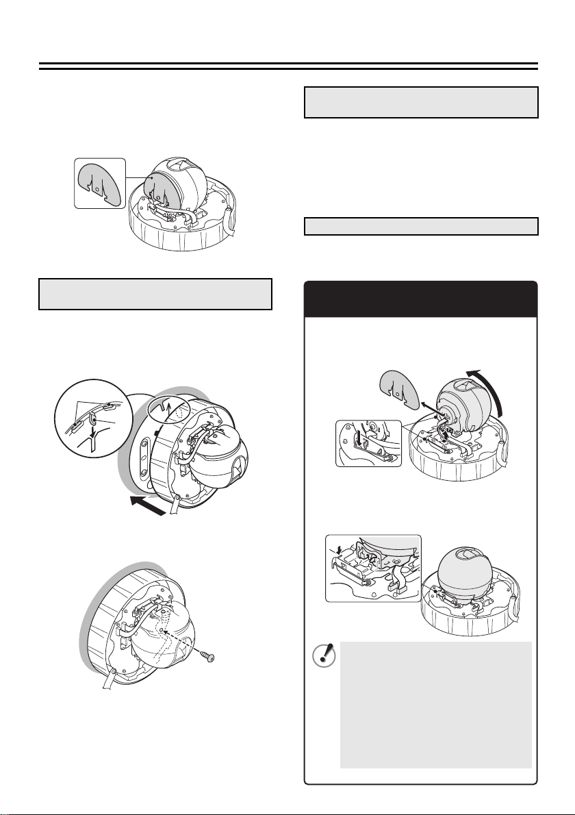
1. Remove the base plate from the
camera unit
Pushing the base plate lock (A), open the
base plate in the arrowed direction.
A
2. Install the base plate
Pass the connection cables through the
1
cable hole on the base plate.
Position the arrow (2) on the base plate
2
in the direction of the lens.
Set the base plate on the ceiling and
3
tighten it securely using suitable screws
and washers (B).
• Length: 35 mm or more
• Diameter: 3.5 to 5.0 mm
• Height of screw head: 5 mm or less
(washer included)
1
3. Connect the cables from the ceiling
Push the excess of connected cables into
the ceiling. For details on the connections,
see page 5.
4. Mount the camera unit to the base
plate
Aligning the ribs (C) and hook (D) on the
camera unit with the slot on the base plate,
push the camera unit until it clicks.
C
D
2
B
B
Make sure to tighten the screws properly.
Using screws of sizes other than
specified may cause the unit to fall.
Make sure that the camera unit and base
plate fit perfectly.
1
Page 3
5. Remove the dome cover
7. Install the dome cover
While pressing down the cabinet section
1
(F) on the opposite side of the rib mark
(E), open the dome cover in the arrowed
direction.
F
Push
Tighten the camera unit securely using
2
the supplied screw (G).
E
G
6. Adjust/Check the video image from
the camera
Align the rib marks (H) and push the dome
cover until it clicks.
H
b Set up the camera remotely (see page 7).
b Check the settings screen or camera
angle on a portable monitor (see page 7).
2
Page 4
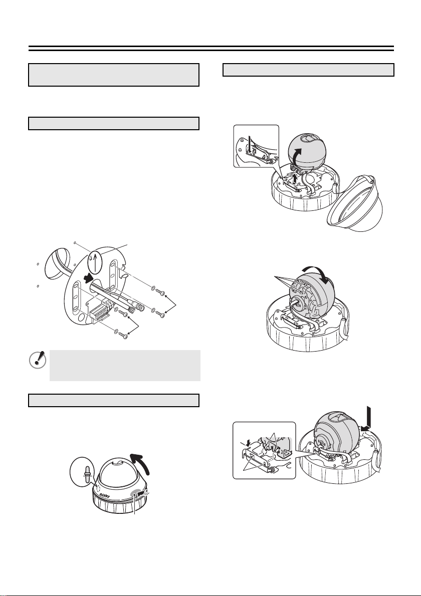
Installing on the Wall
1. Remove the base plate from the
camera unit
See “Installing on the Ceiling” (see page 1).
2. Install the base plate
Pass the connection cables through the
1
cable hole on the base plate.
Set the base plate on the wall with the
2
arrow (↑) pointing upward. Then, secure
the base plate using the screws and
washers (B) (4 places).
• Length: 35 mm or more
• Diameter: 3.5 to 5.0 mm
• Height of screw head: 5 mm or less
(washer included)
2
B
B
Make sure to tighten the screws properly.
Using screws of sizes other than
specified may cause the unit to fall.
3. Remove the dome cover
4. Change the camera position
Push the spring (E) and set free the hooks
1
from the base chassis. Lift and turn the
camera in the arrowed directions so that
the back of the camera becomes visible.
E
Rotate the camera so that the position of
2
the locks (F) is upside down.
F
Align the locks (G) with the slots (H) on
3
the base chassis, push the spring (J),
and mount the camera.
Keep the flat cable away from the chassis.
While pressing down the cabinet section (D)
on the opposite side of the rib mark (C),
open the dome cover in the arrowed
direction.
C
Push
D
G
J
H
3
Page 5
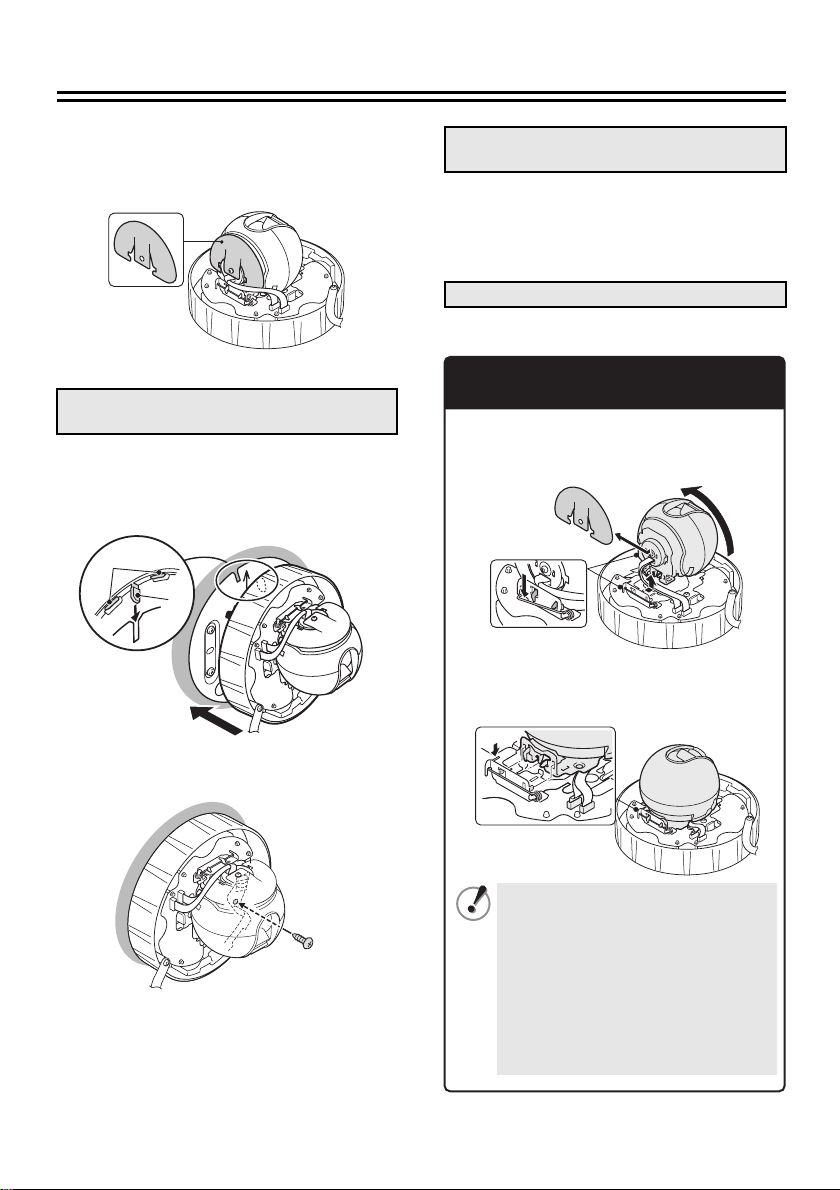
Peel off the release-coated paper of the
4
supplied cover sheet and cover the back
of the camera completely with the sheet,
aligning the hole with the central shaft.
5. Mount the camera unit to the base
plate
Aligning the ribs (K) and hook (L) on the
1
camera unit with the slot on the base
plate, push the camera unit until it
clicks.
K
L
6. Adjust/Check the video image from
the camera
b Set up the camera remotely (see page 7).
b Check the settings screen or camera
angle on a portable monitor (see page 7).
7. Install the dome cover
See “Installing on the Ceiling” (see page 2).
When Moving the Camera from
Wall to Ceiling
1 Remove the cover sheet, being careful not
to distort it.
2 Push the spring and release the camera.
3
Mount the camera by following the opposite
procedure from that indicated in “
the camera position
” (see page 3).
4. Change
Tighten the camera unit securely using
2
the supplied screw (M).
• Check that the flat cable is not
M
caught between the chassis.
• When removing the cover sheet, be
careful not to deform the sheet.
Deformation of the sheet (such as
large wrinkle or bend on the sheet)
may cause the sheet to contact
inside the dome cover when it is
re-attached, which may prevent
normal operation of the camera.
4
Page 6

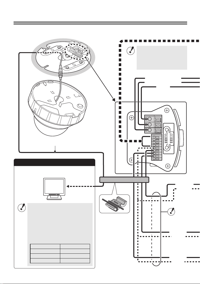
Connections
Do not connect the power cord until all other connections have been completed.
All connection cables
should be 24 AWG or
higher with a maximum
length of no more than
600 m.
<AC 24 V/DC 12 V (+)>
<AC 24 V/DC 12 V (–)>
RG-6U, 300 m max.
<GND>
Monitor Connection
For the connection, use a RG-6U coaxial
cable.
• Using different cables from those
specified here may attenuate the
video and/or sync signals and
interfere with correct transmission.
• RG-59U coaxial cables can be
used when distance between
devices is short, but not in duct or
aerial routing.
Cable type Length
RG-59U (3C-2V) 150 m max.
RG-6U (5C-2V) 300 m max.
RG-11U (7C-2V) 350 m max.
<AL OUT>
<GND>
<AL IN1>
<GND>
<AL IN2>
<GND>
5
Page 7
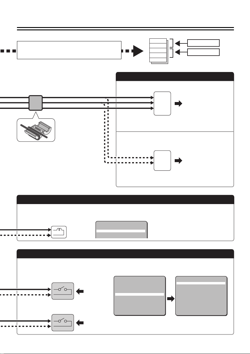
1
Connection for a communication
device for remote operation
CAT5(+)
CAT5(–)
485 (A)
485 (B)
GND
Receiver
Controller
Power Supply Connection
b With AC 24 V
~
~
GND
For the connections, use cables thicker than 18 AWG.
b With DC 12 V
To prevent electromagnetic
interference
• On the cable for power supply
Be sure to attach the supplied
clamping core to the cables as
illustrated.
Check that +/- polarity is correct.
+
–
For the connections, use cables thicker than 18 AWG.
Alarm Signal Output
If a lamp is connected to this cable, it will light up when an alarm signal is received or when the
built-in motion sensor detects movement.
ALARM SETTING
ALARM IN
·ALARM OUT
MOTION
uAREA
1 y
NO
OFF
SET y
Alarm Signal Input
For details, see “Specifying Alarm Input” in the INSTRUCTION MANUAL.
b With Alarm Input 1 (“1” is selected)
SET y
1 y
SEQ y
SET y
SET y
SET y
SET y
SET y
OFF
END
Alarm
input signal
b With Alarm Input 2 (“2” is selected)
Alarm
input signal
CAMERA
PRESET POSITION
AUTO MODE
AUTO RETURN
·ALARM
PASSWORD
LANGUAGE
OPTION
PRESET
MENU
6
ALARM SETTING
·ALARM IN
ALARM OUT
MOTION
uAREA
uSENSITIVITY
ZOOM
uZOOM TIME
DURATION
ALARM SIGN
PRESET
MENU
1 y
NO
OFF
SET y
SET y
OFF
5S
5S
OFF
OFF
BACK
Page 8
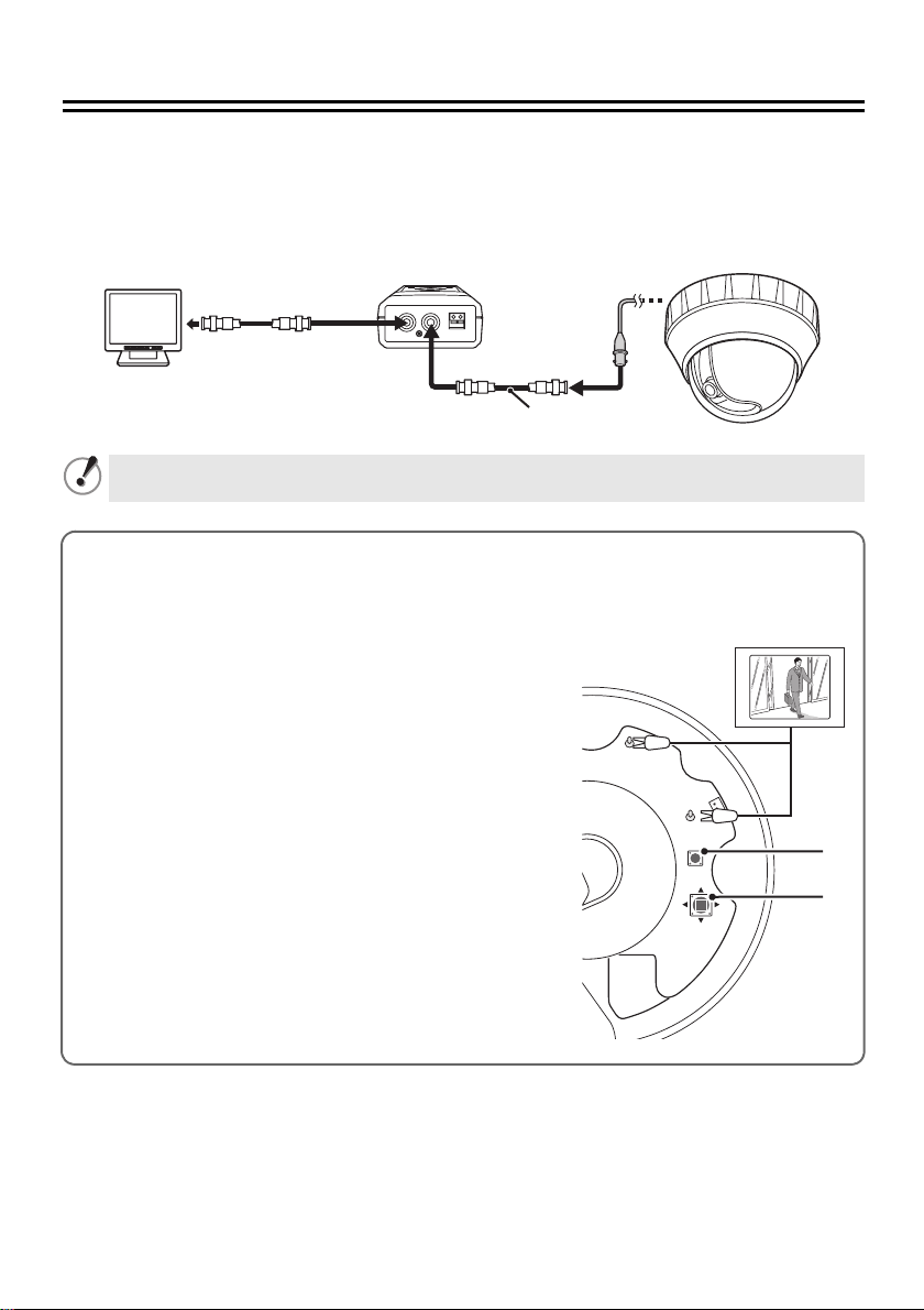
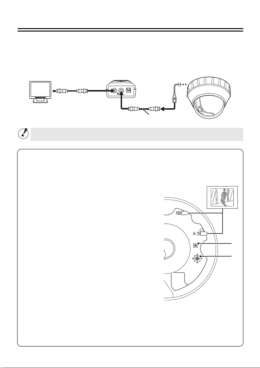
Adjusting the Camera
bSetting up the camera remotely
Use of the separately ordered Camera Control Unit (VAC-70) is recommended for setting and adjustment of
this camera. The Camera Control Unit allows you to adjust the camera angle (pan/tilt, zoom) as well as
perform advanced settings from the main menu. For details, see the instruction manual for the Camera
Control Unit
Checking the settings screen or camera angle on a portable monitor
(These checks are unnecessary when using the separately ordered Camera Control Unit (VAC-70).)
Connect the MONITOR OUT pin and the GND pin on the circuit board to a monitor using an alligator clip cable.
Do not forget to remove the cable after you have finished checking.
A dedicated MONITOR OUT connector is provided for portable monitors.
b To check the settings screen and make changes
1) Hold down the SET button (1) for over a second.
2) Select a menu by pressing the Select button (2) up and
3) Select the setting item and value by pressing the Select
b To check the camera angle and make changes
1) Press the Select button up, down, left, and right during
2) Press the SET button, then press the Select button left
• The active operation switches over between pan/tilt and zoom
.
VAC -7 0
Video in
VIDEO OUT CAMERA
DC IN 3V
Ð+
BNC type
RG-6U coaxial cable
300 m max.
Do not forget to disconnect the Camera Control Unit once you have finished setting/adjustment.
The main menu appears.
GND
down, then press the SET button.
MONITOR
LEFT
OUT
SET
UP
RIGHT
DOWN
button left and right.
live mode (with no menu displayed).
You can set the camera angle (pan: d or c, tilt: j or l).
and right.
You can set the zoom (wide: d, tele: c).
each time you press the SET button.
1
2
7
Page 9
MANUEL D’INSTALLATION
1
Caméra CCD couleurs
CETTE INSTALLATION DOIT ETRE EFFECTUEE PAR UNE
PERSONNE QUALIFIEE DU SERVICE TECHNIQUE ET DOIT
ETRE CONFORME A TOUS LES CODES LOCAUX.
Avant d’installer et d’utiliser cet appareil, veuillez lire avec attention le présent manuel et
respectez toujours les instructions d’utilisation fournies. Lisez aussi le MANUEL
D’INSTRUCTIONS avant d’utiliser l’appareil correctement.
Cet appareil s’installe aussi bien au plafond que sur un mur.
Plafond installé (voir page 1)
(Câblage dans le plafond)
(Câblage en surface)
• Attention lorsque vous percez des trous pour
installer l’appareil. Travaillez avec les câbles
d’alimentation et vidéo sortis pour faciliter
l’installation.
• Lors de l’installation de l’appareil, veillez à
bien imperméabiliser le plafond ou le mur
d’installation.
• Assurez-vous que la surface du lieu
d’installation ne présente aucune irrégularité
et est assez solide pour supporter le poids
total de l’appareil.
• Installez cet appareil dans un environnement
où la plage de températures reste entre
-10°C et +40°C (aucune condensation
autorisée).
• Pour éviter tout dommage électrostatique,
touchez un objet métallique (poignée de porte,
etc.) pour diffuser l’électricité statique dans
votre corps avant de toucher l’appareil.
VCC-P9575P
Important
EnglishFrançaisDeutsch中文简体
Mur installé (voir page 3)
(Câblage dans le mur) (Câblage en surface)
b Accessoires
Plaque de
couverture
2 Vis
3 Noyau de
serrage x2
b Lors du câblage sur le plafond ou le mur :
Ôtez la partie à retirer (B) au-dessus du repère
de nervure (A) avec des pinces et faites passer
les câbles de branchement dans le trou.
B
A
b Intervalles de remplacement des pièces
principales
Si l’appareil est utilisé en continu, les pièces s’usent et
se détériorent en fonction de l’environnement dans
lequel elles sont utilisées.
Il est conseillé de remplacer les pièces environ tous
les 2 ans (approximativement 1 200 000 utilisations)
pour conserver la performance de l’appareil.
• Moteur, câbles utilisés dans les pièces mécaniques,
engrenages, etc.
Page 10
Installation au plafond
1. Enlevez la plaque de base du
groupe caméra
Ouvrez la plaque de base dans la direction
indiquée par la flèche en appuyant sur le
dispositif de blocage de la plaque de
base (A).
A
2. Installez la plaque de base
Faites passer les câbles de
1
branchement à travers le trou prévu à
cet effet dans la plaque de base.
Placez la flèche (2) représentée sur la
2
plaque de base dans la direction de
l’objectif.
Posez la plaque de base au plafond et
3
fixez-la au moyen de vis et de rondelles
adaptées (B).
• Longueur : 35 mm au moins
• Diamètre : 3,5 à 5,0 mm
• Hauteur de la tête de vis : 5 mm maxi
(rondelle incluse)
3. Connectez les câbles à partir du
plafond
Poussez l’excès de câbles connectés dans le
plafond. Pour les détails sur les
branchements, voir page 5.
4. Posez le groupe caméra sur la
plaque de base
Alignez les nervures (C) et le crochet (D) du
groupe caméra avec la fente de la plaque de
base. Appuyez sur le groupe caméra jusqu’à
entendre un clic.
C
D
1
2
B
B
Assurez-vous de bien serrer les vis.
Si vous utilisez des vis d’une taille
différente de celle prescrite, l’appareil
peut tomber.
Assurez-vous que le groupe caméra et la
plaque de base sont parfaitement
emboîtés.
1
Page 11

5. Ôtez le couvercle du dôme
7. Installation du couvercle du dôme
Tout en appuyant sur la section (F) se
1
trouvant à l’opposé du repère de nervure
(E), ouvrez le couvercle du dôme dans la
direction indiquée par la flèche.
F
Pousser
Fixez bien le groupe caméra au moyen
2
de la vis fournie (G).
E
G
6. Ajustez/Contrôlez l’image vidéo
de la caméra
Alignez les repères des nervures (H) et
appuyez sur le couvercle du dôme jusqu’à
entendre un clic.
H
b Configurez la caméra à distance
(voir page 7).
b Contrôlez l’écran des réglages ou l’angle
de la caméra sur un moniteur portable
(voir page 7).
2
Page 12

Installation sur le mur
1. Enlevez la plaque de base du
groupe caméra
Consultez « Installation au plafond »
(voir page 1).
2. Installez la plaque de base
Faites passer les câbles de
1
branchement à travers le trou prévu à
cet effet dans la plaque de base.
Placez la plaque de base sur le mur en
2
tournant la flèche (↑) vers le haut. Puis
fixez la plaque de base au moyen des vis
et des rondelles (B) (4 emplacements).
• Longueur : 35 mm au moins
• Diamètre : 3,5 à 5,0 mm
• Hauteur de la tête de vis : 5 mm maxi
(rondelle incluse)
2
B
4. Changement de position de la
caméra
Poussez le ressort (E) et débloquez les
1
crochets du châssis de la base. Soulevez
et tournez la caméra dans la direction de
la flèche, de manière que l’arrière de la
caméra devienne visible.
E
Tournez la caméra de manière que les
2
verrous (F) soient à l’envers.
F
B
Assurez-vous de bien serrer les vis.
Si vous utilisez des vis d’une taille
différente de celle prescrite, l’appareil
peut tomber.
3. Ôtez le couvercle du dôme
Tout en appuyant sur la section (D) se
trouvant à l’opposé du repère de nervure (C),
ouvrez le couvercle du dôme dans la
direction indiquée par la flèche.
C
Pousser
D
Alignez les verrous (G) sur les fentes (H)
3
du châssis de la base, poussez le
ressort (J) et montez la caméra.
Maintenez le câble plat à l’écart du châssis.
G
J
H
3
Page 13
Retirerez le papier de protection de la
4
plaque de couverture fournie et couvrez
complètement l’arrière de la caméra
avec la plaque, en alignant le trou sur
l’axe central.
6. Ajustez/Contrôlez l’image vidéo de
la caméra
b Configurez la caméra à distance
(voir page 7).
b Contrôlez l’écran des réglages ou l’angle
de la caméra sur un moniteur portable
(voir page 7).
7. Installation du couvercle du dôme
Consultez « Installation au plafond »
(voir page 2).
5. Posez le groupe caméra sur la
plaque de base
Alignez les nervures (K) et le crochet (L)
1
du groupe caméra avec la fente de la
plaque de base. Appuyez sur le groupe
caméra jusqu’à entendre un clic.
K
L
Fixez bien le groupe caméra au moyen
2
de la vis fournie (M).
M
Lors du déplacement de la
caméra du mur au plafond
1 Retirez la plaque de couverture, en vous
assurant de ne pas la tordre.
2 Poussez le ressort et libérez la caméra.
3
Montez la caméra en inversant la procédure
indiquée au point «
position de la caméra
• Assurez-vous que le câble plat n’est
pas pris dans le châssis.
• Lors de son retrait, veuillez à ne pas
déformer la plaque de couverture.
Une déformation de la plaque (par
exemple un pli) peut provoquer un
contact entre la plaque et l’intérieur du
couvercle du dôme lors de la remise
en place de la plaque. Ceci risquerait
de gêner le fonctionnement normal de
la caméra.
4. Changement de
» (voir page 3).
4
Page 14
Branchements
Ne branchez pas le cordon d’alimentation tant que les autres branchements n’ont pas ete
effectues.
Tous les câbles de
branchement doivent
être au moins 24 AWG et
d’une longueur
maximale de 600 m.
<AC 24 V/DC 12 V (+)>
<AC 24 V/DC 12 V (–)>
<GND>
RG-6U, 300 m maxi
Branchement du moniteur
Pour la connexion, utilisez un câble coaxial
RG-6U.
• L’utilisation de câbles autres que
ceux spécifiés peut atténuer les
signaux vidéo et/ou sync et réduire
la qualité de la transmission.
Des câbles coaxiaux RG-59U peuvent
•
être utilisés lorsque la distance entre
les appareils est courte, mais pas
dans un câblage dans une gaine ou
une antenne.
Type de câble Longueur
RG-59U (3C-2V) 150 m maxi
RG-6U (5C-2V) 300 m maxi
RG-11U (7C-2V) 350 m maxi
<AL OUT>
<GND>
<AL IN1>
<GND>
<AL IN2>
<GND>
5
Page 15

Connexion pour un appareil de
communication en vue de la
commande à distance
CAT5(+)
CAT5(–)
485 (A)
485 (B)
GND
Récepteur
Contrôleur
1
Connexion de l’alimentation
b Avec CA 24 V
~
~
GND
Pour les connexions, utilisez des câbles d’une
épaisseur supérieure à 18 AWG.
b Avec CC 12 V
Pour empêcher les interférences
électromagnétiques
• Sur le câble d’alimentation
Veillez à bien fixer le noyau de ferrite
fourni aux câbles comme le montre
la figure.
Vérifiez si la polarité +/- est correcte.
+
–
Pour les connexions, utilisez des câbles d’une
épaisseur supérieure à 18 AWG.
Sortie du signal d’alarme
Si un témoin est relié à ce câble, il s’allume lorsqu’un signal d’alarme est reçu ou lorsque le capteur
intégré détecte un mouvement.
REGLAGE ALARME
ENT ALARME
·SORTIE ALARME
MOUVEMENT
uZONE
1 y
NO
ARR
REG y
Entrée du signal d’alarme
Pour les détails, voir « Spécification de l’entrée d’alarme » dans le MANUEL D’INSTRUCTIONS.
b Avec l’entrée d’alarme 1
(« 1 » est sélectionné)
b Avec l’entrée d’alarme 2
(« 2 » est sélectionné)
Alarme
signal
d’entrée
Alarme
signal
d’entrée
CAMERA
POS.PREDEFINIE
MODE AUTO
RETOUR AUTO
·ALARME
M/PASSE
LANGUE
OPTION
PREREGLAGE
MENU
REG y
1 y
SEQ y
ARR
REG y
REG y
REG y
REG y
ARR
FIN
REGLAGE ALARME
·ENT ALARME
SORTIE ALARME
MOUVEMENT
uZONE
uSENSIBILITE
ZOOM
uTEMPS ZOOM
DUREE
SIGNAL ALARME
PREREGLAGE
MENU
1 y
NO
ARR
REG y
REG y
ARR
5S
5S
ARR
ARR
RETOUR
6
Page 16
Ajustage de la caméra
bConfiguration de la caméra à distance
L’utilisation de la télécommande pour caméra (VAC-70) commandée séparément est recommandée pour la
configuration et le réglage de cette caméra. La télécommande pour caméra vous permet d’ajuster l’angle de la caméra
(mise au point panoramique/inclinaison, zoom) et d’effectuer les réglages avancés à partir du menu principal. Pour les
détails, consultez le manuel d’instructions pour la télécommande pour caméra
VAC -7 0
Entrée vidéo
VIDEO OUT CAMERA
DC IN 3V
Ð+
N’oubliez pas de débrancher la télécommande pour caméra après la configuration/le réglage.
Contrôle de l’écran des réglages ou de l’angle de la caméra sur un moniteur portable
(Ces contrôles ne sont pas nécessaires si vous utilisez la télécommande pour caméra (VAC-70)
commandée séparément.) Reliez la broche MONITOR OUT et la broche GND de la carte de circuit
imprimé à un moniteur avec un câble pourvu d’une pince crocodile. N’oubliez pas de retirer le câble
une fois la vérification terminée.
Un connecteur MONITOR OUT dédié est fournis pour les
moniteurs portables.
b Pour contrôler l’écran des réglages et effectuer les
modifications
1) Maintenez enfoncé le bouton SET (1) pendant plus
d’une seconde.
Le menu principal apparaît.
2) Sélectionnez un menu en appuyant sur le bouton de
sélection (2) en haut et en bas, puis appuyez sur le
bouton SET.
3) Sélectionnez la rubrique et la valeur de réglage en
appuyant sur le bouton de sélection à gauche et à droite.
b Pour contrôler l’angle de la caméra et effectuer les
modifications
1) Appuyez sur le bouton de sélection en haut, en bas, à
gauche, à droite en mode direct (aucun menu affiché).
Vous pouvez régler l’angle de la caméra (panoramique : d
ou c, inclinaison : j ou l).
2) Appuyez sur le bouton SET, puis sur le bouton de
sélection à gauche et à droite.
Vous pouvez régler le zoom (grand-angle : d, téléobjectif : c).
• Le mode actif commute entre mise au point
panoramique/inclinaison et zoom, chaque fois que vous
appuyez sur le bouton SET.
.
Type BNC
Câble coaxial RG-6U
300 m maxi
GND
LEFT
MONITOR
OUT
SET
UP
RIGHT
DOWN
1
2
7
Page 17

INSTALLATIONSANLEITUNG
CCD-Farbkamera
DIESE INSTALLATION IST QUALIFIZIERTEM
SERVICE-PERSONAL VORBEHALTEN UND MUSS MIT ALLEN
LOKALEN GESETZESVORSCHRIFTEN KONFORM SEIN.
Lesen Sie diese Anleitung vor der Installation und Verwendung der Einheit bitte sorgfältig durch und
befolgen Sie die Anweisungen für den richtigen Gebrauch. Bitte lesen Sie auch die separate
BEDIENUNGSANLEITUNG, bevor Sie die Kamera einsetzen, um den richtigen Gebrauch zu gewährleisten.
Diese Kamera ist für die Wand- oder
Deckeninstallation ausgelegt.
Deckeninstallation (siehe Seite 1)
(Unterputzverlegung an der Decke)
(Überputzverlegung)
• Vorsicht bei der Anbringung von Löchern
für die Installierung der Einheit. Ziehen Sie
Netz- und Videokabel während der Arbeit,
um die Installierung zu vereinfachen.
• Stellen Sie sicher, dass die Decken- oder
Wandinstallation der Einheit wasserdicht
ausgeführt.
• Stellen Sie sicher, dass der Installationsort
für das Gewicht der Kamera ausreichend
tragfähig ist und eine ebene Oberfläche
aufweist.
• Installieren Sie die Einheit an einem Ort mit
Temperaturen zwischen -10°C und +40°C
(nicht kondensierend).
• Berühren Sie zur Vermeidung von Schäden
durch elektrostatische Entladungen einen
Metallgegenstand in der Nähe (Türknauf
o.Ä.), damit die statische Ladung aus Ihrem
Körper abgeleitet wird, bevor Sie die Einheit
berühren.
VCC-P9575P
Wichtiger Hinweis
EnglishFrançaisDeutsch中文简体
Wandinstallation (siehe Seite 3)
(Unterputzverlegung
an der Wand)
b Zubehör
1 Deckplatte 2 Schraube
(Überputzverlegung)
3 Ferritkern x2
b Beachten Sie Folgendes für die Decken-
oder Wandverlegung von Kabeln:
Den oberhalb der Rippenkennzeichnung (A)
angeordneten Auswerferstift (B) mit einer kleinen
Zange usw. abdrehen und die Verbindungskabel durch
das Loch führen.
B
A
b Empfohlenes Austauschintervall für die
wichtigsten Bauteile
Bei Dauerbetrieb hängt der Verschleiß der Bauteile von
der Betriebsumgebung ab.
Zur Gewährleistung einer gleichbleibenden
Geräte-Performance wird empfohlen, diese Bauteile
ungefähr alle zwei Jahre (d.h. nach ungefähr 1.200.000
Nutzungen) auszutauschen.
• Motor, in mechanischen Gruppen verwendete
Kabel, Getriebe, usw.
Page 18

Deckeninstallation
1. Die Grundplatte von der Kamera
abnehmen
Druck auf die Arretierung der Grundplatte
(A) ausüben; Grundplatte in Pfeilrichtung
öffnen.
A
2. Die Grundplatte installieren
Verbindungskabel durch die Kabellöcher
1
der Grundplatte führen.
Die Pfeile (2) auf der Grundplatte in
2
Richtung Objektiv ausrichten.
Grundplatte an der Decke aufsetzen und
3
einwandfrei mit geeigneten Schrauben
und Unterlegscheiben (B) befestigen.
• Länge: mindestens 35 mm
• Durchmesser: 3,5 - 5,0 mm
• Höhe des Schraubenkopfes: höchstens
5 mm (einschließlich Unterlegscheiben)
1
3. Die Kabel von der Decke
anschließen
Überstehende Anschlusskabel wieder
zurück in die Decke drücken. Für
Einzelheiten über die Anschlüsse, siehe
Seite 5.
4. Kamera auf der Grundplatte
montieren
Die an der Kameraeinheit angebrachten
Rippen (C) und die Feder (D) mit dem Schlitz
auf der Grundplatte in Übereinstimmung
bringen und die Kameraeinheit bis zum
Einrasten andrücken.
C
D
2
B
B
Stellen Sie sicher, dass die Schrauben
fest angezogen sind. Die Einheit kann
herunterfallen, wenn die Größe der
Befestigungsschrauben nicht den
Spezifikationen entspricht.
Stellen Sie sicher, dass die
Kameraeinheit einwandfrei mit der
Grundplatte verbunden ist.
1
Page 19

5. Die Kuppelabdeckung abnehmen
7. Montage der Kuppelabdeckung
Um die Kuppelabdeckung zu öffnen,
1
drücken Sie auf den gegenüber der
Rippenkennzeichnung (E) liegenden
Gehäuseabschnitt (F) und drehen die
Kuppelabdeckung in Pfeilrichtung.
F
Drücken
Befestigen Sie die Kameraeinheit mit den
2
mitgelieferten Schrauben (G). Fest
anziehen.
E
G
Rippenkennzeichnung (H) in
Übereinstimmung bringen und die
Kuppelabdeckung bis zum hörbaren
Einrasten andrücken.
H
6. Überprüfung und ggf. Anpassung
der von der Kamera erzeugten
Bildschirmanzeige
b Grundeinstellungen der Kamera mit der
Fernsteuerung vornehmen
siehe Seite 7
(
b Einstellbildschirm oder Aufnahmewinkel
auf einem tragbaren Monitor überprüfen
siehe Seite 7)
(
).
.
2
Page 20

Wandinstallation
1. Die Grundplatte von der Kamera
abnehmen
Siehe „Deckeninstallation“ (siehe Seite 1).
2. Die Grundplatte installieren
Verbindungskabel durch die Kabellöcher
1
der Grundplatte führen.
Grundplatte an der Wand aufsetzen.
2
Achten Sie darauf, dass der Pfeil (↑) nach
oben zeigt. Grundplatte mit den
Schrauben und Unterlegscheiben (B) (4x)
befestigen.
• Länge: mindestens 35 mm
• Durchmesser: 3,5 - 5,0 mm
• Höhe des Schraubenkopfes: höchstens
5 mm (einschließlich Unterlegscheiben)
2
B
B
4.Die Position der Kamera verändern
Druck auf die Feder (E) ausüben und die
1
Haken an der Gehäusebasis freigeben.
Kamera anheben und in Pfeilrichtung
drehen, bis die Rückseite der Kamera
sichtbar wird.
E
Kamera so drehen, dass eine Umkehrung
2
der Position der Arretierungen (F) erzielt
wird.
F
Stellen Sie sicher, dass die Schrauben
fest angezogen sind. Die Einheit kann
herunterfallen, wenn die Größe der
Befestigungsschrauben nicht den
Spezifikationen entspricht.
3. Die Kuppelabdeckung abnehmen
Um die Kuppelabdeckung zu öffnen, drücken
Sie auf den gegenüber der
Rippenkennzeichnung (C) liegenden
Gehäuseabschnitt (D) und drehen die
Kuppelabdeckung in Pfeilrichtung.
C
Drücken
D
Die Arretierungen (G) mit den Schlitzen
3
(H) an der Gehäusebasis in
Übereinstimmung bringen, Druck auf die
Feder (J) ausüben und die Kamera
montieren.
Das Flachkabel muss stets vom Gehäuse
ferngehalten werden.
G
J
H
3
Page 21

Ziehen Sie die selbstklebende
B
Papierschicht von der mitgelieferten
Deckplatte ab. Decken Sie die Rückseite
der Kamera vollständig mit der
Deckplatte ab und bringen Sie dabei das
Loch mit dem zentralen Schaft in
Übereinstimmung.
5. Kamera auf der Grundplatte
montieren
Die an der Kameraeinheit angebrachten
1
Rippen (K) und die Feder (L) mit dem
Schlitz auf der Grundplatte in
Übereinstimmung bringen und die
Kameraeinheit bis zum Einrasten
andrücken.
K
L
6. Überprüfung und ggf. Anpassung
der von der Kamera erzeugten
Bildschirmanzeige
b Grundeinstellungen der Kamera mit der
Fernsteuerung vornehmen (
b Einstellbildschirm oder Aufnahmewinkel
auf einem tragbaren Monitor überprüfen
siehe Seite 7
(
).
siehe Seite 7
7. Montage der Kuppelabdeckung
Vergleiche „Deckeninstallation“ (siehe Seite 2).
Bei Umrüstung von der Wand- zur
Deckeninstallation der Kamera
1 Nehmen Sie die Deckplatte vorsichtig ab,
ohne sie zu verbiegen.
2 Druck auf die Feder ausüben und die Kamera
freisetzen.
3
Montieren Sie die Kamera, wobei Sie die unter
„4. Die Position der Kamera verändern“
Punkt
beschriebenen Schritte in umgekehrter
Reihenfolge ausführen (siehe Seite 3).
).
Befestigen Sie die Kameraeinheit mit den
2
mitgelieferten Schrauben (M). Fest
anziehen.
M
• Achten Sie darauf, dass das Flachkabel
nicht zwischen dem Gehäuse
eingeklemmt wird.
• Achten Sie beim Abnehmen der Deckplatte
sorgfältig darauf, diese nicht zu verbiegen.
Eine Verformung der Deckplatte (z.B. größere
Falten oder Biegungen der Platte) kann beim
Ankleben zu Kontakten innerhalb der
Kuppelabdeckung führen und den normalen
Betrieb der Kamera beeinträchtigen.
4
Page 22

Anschlüsse
Das Netzkabel nicht anschließen, bevor nicht alle anderen Anschlüsse ausgeführt wurden.
Alle Anschlusskabel
müssen mindestens
24 AWG entsprechen und
die Länge darf nicht mehr
als 600 m betragen.
<AC 24 V/DC 12 V (+)>
<AC 24 V/DC 12 V (–)>
<GND>
RG-6U, max. 300 m
Monitoranschluss
Verwenden Sie für den Anschluss ein
RG-6U-Koaxialkabel.
•
Die Verwendung von nicht mit den
Spezifikationen konformen Kabeln kann
die Video- und/oder
Synchronisationssignalen schwächen und
die korrekte Übertragung beeinträchtigen.
• RG-59U-Koaxialkabel können
verwendet werden, wenn der Abstand
zwischen den Geräten kurz ist, aber
nicht bei Kabelkanälen oder an
Außenwänden verlegten Leitungen.
Kabeltyp Länge
RG-59U (3C-2V) max. 150 m
RG-6U (5C-2V) max. 300 m
RG-11U (7C-2V) max. 350 m
<AL OUT>
<GND>
<AL IN1>
<GND>
<AL IN2>
<GND>
5
Page 23

Anschluss für ein
Kommunikationsgerät zur
Fernbedienung
CAT5(+)
CAT5(–)
485 (A)
485 (B)
GND
Empfänger
Controller
1
Netzanschluss
b Mit AC 24 V
~
~
GND
Verwenden Sie für die Anschlüsse Kabel mit einem
Durchmesser von mehr als 18 AWG.
b Mit DC 12 V
Vermeiden von
elektromagnetischen Störungen
• Am Kabel der Stromversorgung
Den mitgelieferten Ferritkern wie
abgebildet an den Anschlusskabeln
anbringen.
Prüfen Sie, ob die +/- Polarität richtig ist.
+
–
Verwenden Sie für die Anschlüsse Kabel mit einem
Durchmesser von mehr als 18 AWG.
Alarmausgangssignal
Wenn eine Lampe an dieses Kabel angeschlossen ist, leuchtet diese auf, wenn ein Alarmsignal
empfangen wird oder wenn der eingebaute Bewegungssensor ein bewegtes Objekt erfasst hat.
EINSTELLUNG ALARM
ALARM EIN
·ALARM AUS
BEWEGUNGSENSOR
uBEREICH
1 y
NO
AUS
EINSTy
Alarmeingangsignal
Weitere Einzelheiten finden Sie in der BEDIENUNGSANLEITUNG, im Abschnitt „Vorgabe des
Alarmeingangs“.
b Mit Alarmeingang 1 („1“ ist aktiviert)
Alarmeingangssignal
b Mit Alarmeingang 2 („2“ ist aktiviert)
Alarmeingangssignal
KAMERA
POS.VOREINST.
AUTO-MODUS
AUTOM.ZURUECK
·ALARM
KENNWORT
SPRACHE
OPTION
VOREINST.
MENUE
EINSTy
1 y
SEQ y
AUS
EINSTy
EINSTy
EINSTy
EINSTy
AUS
ENDE
EINSTELLUNG ALARM
·ALARM EIN
ALARM AUS
BEWEGUNGSENSOR
uBEREICH
uEMPFINDLICHK.
ZOOM
uZOOMZEIT
DAUER
ALARMZEICHEN
VOREINST.
MENUE
1 y
NO
AUS
EINSTy
EINSTy
AUS
5S
5S
AUS
AUS
ZURUECK
6
Page 24

Einstellen der Kamera
bFerngesteuertes Einstellen der Kamera
Für die Einstellungen und Justierung der Kamera wird der Einsatz des gesondert erhältlichen Kamerasteuergeräts
(VAC-70) empfohlen. Das Kamerasteuergerät gestattet es, den Aufnahmewinkel (Schwenken/Kippen, Zoom)
anzupassen und komplexere Einstellungen im Hauptmenü der Kamera vorzunehmen. Für Einzelheiten wird auf die
Bedienungsanleitung des Kamerasteuergeräts verwiesen.
VAC -7 0
Video ein
Vergessen Sie nicht, das Kamerasteuergerät von der Verbindung zu trennen, sobald Sie mit den
Einstellungen/Anpassungen fertig sind.
Einstellbildschirm oder Aufnahmewinkel auf einem tragbaren Monitor überprüfen
(Diese Kontrollen sind unnötig, wenn Sie das gesondert erhältliche Kamerasteuergerät (VAC-70)
einsetzen.) Den Stecker MONITOR OUT und den Stecker GND mit einem Kabel mit Krokodilklemme
von der Schaltplatine mit einem Monitor verbinden. Vergessen Sie nicht, das Kabel zu ziehen,
nachdem Sie diesen Kontrollvorgang beendet haben.
Für den Anschluss eines tragbaren Monitors wird ein
spezifischer MONITOR OUT-Stecker mitgeliefert.
b
Zur Überprüfung und Anpassung des Einstellbildschirms
1) Halten Sie die SET-Taste (1) länger als eine Sekunde
gedrückt.
Das Hauptmenü wird eingeblendet.
2) Drücken Sie die Auswahltaste (2) auf- oder abwärts, um
ein Menü auszuwählen und bestätigen dann mit der
SET-Taste.
3) Wählen Sie eine Einstellung, indem Sie die Auswahltaste
nach rechts oder links drücken.
b Zur Überprüfung und Anpassung des Aufnahmewinkels
1) Drücken Sie die Auswahltaste im Live-Modus auf- oder
abwärts, bzw. nach links oder rechts (ohne Menüanzeige).
Sie können nun den Aufnahmewinkel einstellen
(Schwenken: d oder c, Kippen: j oder l).
2) Drücken Sie erst die SET-Taste und dann die
Auswahltaste nach links oder rechts.
Sie können nun den Zoomfaktor einstellen (Weitwinkel: d,
Te le : c).
• Bei laufendem Betrieb schaltet die Kamera bei jeder
Betätigung der SET-Taste zwischen der Schwenk- und
Kippfunktion bzw. dem Zoom um.
VIDEO OUT CAMERA
DC IN 3V
Ð+
BNC Typ
RG-6U Koaxialkabel
Höchstens 300 m
GND
MONITOR
OUT
LEFT
SET
UP
RIGHT
DOWN
1
2
7
Page 25

安装手册
彩色 CCD 摄像机
本摄像机的安装应由合格的维修人员来执行,且应遵守所有的地方
法规。
在安装和使用本机之前,请仔细阅读本手册,并始终遵照本手册中的说明正确使用。此外,也请您在使
用本机前,仔细阅读单独的说明手册以便正确使用。
本机可安装在天花板或墙壁上。
天花板安装方式 (参见第1页)
(天花板内的布线)
(表面的布线)
• 请小心掀开安装本机时所使用的孔。为求方
便安装,请使用拉出的电源和视频电缆。
• 请确保要安装本机的天花板或墙壁已经做好
适当的防水处理。
• 请勿将本机安装在表面凹凸不平的位置上,
并且安装位置能够承受本机的整体重量。
• 本机的安装环境温度需保持在-10°C到+40°C
之间 (不允许有冷凝)。
• 为了预防静电产生的损坏,请在触摸本机之
前,先触摸附近的金属物体 (如门把等),
让身上的静电消散。
VCC-P9575P
重要事项
EnglishFrançaisDeutsch中文简体
墙壁安装方式 (参见第3页)
(墙内的布线) (表面的布线)
b 附件
1 机盖片 2 螺钉
3 卡榫屏蔽环x2
b 当您在天花板或墙面布线时:
使用一对钳子等其他工具将肋标记 (A)上面的
脱离片 (B)扭转下来,并将连接电缆穿过孔
洞。
B
A
b 主要零件更换时间
如果本机有连续使用,零件将会磨损并恶化 (根
据使用环境而定)。
建议约每两年 (约1,200,000次)更换零件一次,
以维护装置的性能。
• 电动机、机械零件中使用的电缆、齿轮等
Page 26

在天花板上安装
1. 卸下摄像机装置底座
推动底座锁 (A),按箭头方向开启底座。
A
2. 装上底座
将连接电缆穿过底座上的电缆孔。
1
让底座上的箭头 (2)指向镜头的方向。
2
将底座装上天花板并使用合适的螺钉与垫圈
3
(B)将其拧紧。
• 长度:35 mm或以上
• 直径: 3.5至5.0 mm
• 螺钉头的高度: 等于或小于5 mm (含垫
圈)
1
2
3. 连接天花板的电缆
将过长的连接电缆塞回天花板里。有关连接的详
细信息,请参见第 5 页。
4. 将摄像机装置安装在底座上
将摄像机装置上的肋 (C)与勾子 (D)与底座
上的插槽对齐,推动摄像机装置直到发出喀嚓
声。
C
D
B
B
确保已完全拧紧螺钉。如未使用特定大小
的螺钉,很有可能使本机掉落。
确保摄像机装置与底座匹配完好。
1
Page 27

5. 取下球罩
7. 安装球罩
当按下肋标记 (E)对面的机柜部位 (F)
1
时,请按箭头方向开启球罩。
F
压
E
使用随附的螺钉 (G)将摄像机装置拧紧。
2
G
6. 调整/查看摄像机视频的图像
b 遥控设置摄像机 (参见本安装手册的背面)。
b 在便携式监视器上检查设定屏幕和摄像机的角
度 (参见本安装手册的背面)。
将肋标记 (H)对齐并推动球罩直到发出喀擦
声。
H
2
Page 28

在墙上安装
1. 卸下摄像机装置底座
请参见 “在天花板上安装”(参见第 1 页)。
2. 装上底座
将连接电缆穿过底座上的电缆孔。
1
将底座安装在墙上并使其箭头 (↑)指向上
2
方。然后,使用螺钉与垫圈 (B)( 4个位
置)固定底座。
• 长度:35 mm或以上
• 直径: 3.5至5.0 mm
• 螺钉头的高度: 等于或小于5 mm (含垫
圈)
2
B
B
确保已完全拧紧螺钉。如未使用特定大小
的螺钉,很有可能使本机掉落。
3. 取下球罩
4. 改变摄像机的位置
按下弹簧 (E)并且放开底盘的勾子。将摄
1
像机拿起并且旋转到箭头所指的方向,以便
看清楚摄像机的背面。
E
旋转摄像机,直到锁 (F)倒立为止
2
F
将锁 (G)和底盘上的插槽 (H)对齐,按
3
下弹簧 (J),然后安装摄像机。
请让扁平电缆远离底盘。
当按下肋标记 (C)对面的机柜部位 (D)时,
请按箭头方向开启球罩。
C
压
D
G
J
H
3
Page 29

将机盖片的防粘涂布纸剥下,并用随附的机
4
盖片将摄像机的背面完全覆盖,让孔与中心
轴对齐。
6. 调整/查看摄像机视频的图像
b 遥控设置摄像机 (参见本安装手册的背面)。
b 在便携式监视器上检查设定屏幕和摄像机的角
度 (参见本安装手册的背面)。
7. 安装球罩
请参见 “在天花板上安装”(参见第 2 页)。
5. 将摄像机装置安装在底座上
将摄像机装置上的肋 (K)与勾子 (L)与
1
底座上的插槽对齐,推动摄像机装置直到发
出喀嚓声。
K
L
使用随附的螺钉 (M)将摄像机装置拧紧。
2
M
把摄像机从墙上移到天花板时
1 小心卸下机盖片,请勿将其扭曲。
2 按下弹簧并取下摄像机。
3 请按 “4. 改变摄像机的位置”步骤所示的
相反过程安装摄像机 (参见第3页)。
• 请检查扁平电缆没有缠绕在底盘之
间。
• 卸下机盖片时,请勿将其扭曲。 机
盖片的变形 (如机盖片上的大片绉
纹或弯曲)可能会在重新装上机盖
片时使其接触到球罩的内面,这样
会使摄像机无法正常操作。
4
Page 30

连接
在其它连接尚未完成之前,请勿连接电源线。
RG-6U,最长300 m
所有连接电缆应是最
大长度不大于 600m
的 24 AWG 或更高级
的电缆。
<AC 24 V/DC 12 V (+)>
<AC 24 V/DC 12 V (-)>
<GND>
监视器连接
请使用RG-6U同轴电缆连接。
• 如果使用与这些指定类型不同的电
缆,视频和/或同步信号将会被削
弱和受到干扰而无法正常传输。
• 当装置之间的距离很短时,可以使
用RG-59U同轴电缆,但不能在管
线或是天线布线中使用。
电缆类型 长度
RG-59U(3C-2V)
RG-6U(5C-2V)
RG-11U(7C-2V)
最长 150 m
最长 300 m
最长 350 m
<AL OUT>
<GND>
<AL IN1>
<GND>
<AL IN2>
<GND>
5
Page 31

1
通信设备遥控操作的连接
CAT5(+)
CAT5(–)
485 (A)
485 (B)
GND
接收器
控制器
电源线的连接
b 使用AC 24 V
~
~
GND
请使用比18 AWG粗的电缆进行连接。
b 使用DC 12 V
防止电磁干扰
• 电源线上
请务必按图示将随附的卡榫屏蔽环连
接到电缆上。
检查正负极性是否正确。
+
–
请使用比18 AWG粗的电缆进行连接。
报警信号输出
如果此电缆已连接到指示灯,当接收到报警信号或是内置运动传感器检测到运动时,该灯就会亮起。
ALARM SETTING
ALARM IN
·ALARM OUT
MOTION
uAREA
1 y
NO
OFF
SET y
报警信号输入
有关详细信息,请参见说明手册中的 “指定报警输入”。
b 含报警输入1 (选定 “1”)
报警输入信号
b 含报警输入2 (选定 “2”)
报警输入信号
CAMERA
PRESET POSITION
AUTO MODE
AUTO RETURN
·ALARM
PASSWORD
LANGUAGE
OPTION
PRESET
MENU
6
SET y
1 y
SEQ y
SET y
SET y
SET y
SET y
SET y
OFF
END
ALARM SETTING
·ALARM IN
ALARM OUT
MOTION
uAREA
uSENSITIVITY
ZOOM
uZOOM TIME
DURATION
ALARM SIGN
PRESET
MENU
1 y
NO
OFF
SET y
SET y
OFF
5S
5S
OFF
OFF
BACK
Page 32

调整摄像机
b遥控设置摄像机
建议使用单独订购的摄像机控制器 (VA C - 7 0 )设置和调整此摄像机。 摄像机控制器使您可以调整摄像机
的角度 (摇摆度 / 倾斜度,变焦)和在主菜单中执行高级设定。有关详细信息,请参见摄像机控制器的
使用手册。
VAC - 7 0
视频输入
一旦您结束设置/调整,请记得将摄像机控制器断开。
在便携式监视器上检查设定屏幕和摄像机的角度。
(当使用单独订购的摄像机控制器 (VA C - 7 0 )时,这些检查是不必要的。)
使用带鳄鱼夹的电缆将电路板上的MONITOR OUT引脚和GND引脚连接到监视器。结束检查之后,
请记得查取下电缆。
有一个专用的MONITOR OUT接头提供给便携式监视器使用。
b 检查设定屏幕并做出更改
1) 按住SET按钮 (1)约一秒以上。
主菜单就会出现。
2) 上下按 “选择”按钮 (2)选择一个菜单,然后按下SET按
钮。
3) 左右按下 “选择”按钮选择设置项和值。
b 检查摄像机角度并做出更改
1) 在实况模式下上、下、左、右按 “选择”按钮 (没有显示菜
单)。
您可以设置摄像机的角度 (摇摆度:d 或 c,倾斜度:j
或 l)。
2) 按下SET按钮,然后左右按下 “选择”按钮。
您可以设置变焦 (广角:d,伸缩:c)。
• 每次按下SET按钮时,就可以在摇摆度/倾斜度和变焦之间切
换进行中的操作。
VIDEO OUT CAMERA
DC IN 3V
Ð+
BNC类型
RG-6U同轴电缆
最长300 m
GND
MONITOR
OUT
LEFT
SET
UP
RIGHT
DOWN
1
2
Printed on recycled paper
Imprimé sur du papier recyclé
Gedruckt auf Recyclingpapier
使用再生纸印刷
1AC6P1P3089-L5BM2/XE (0706KP-SY)
SANYO Electric Co., Ltd.
Printed in Japan
 Loading...