

Page 1
Technical Manual (Ver 1.03)
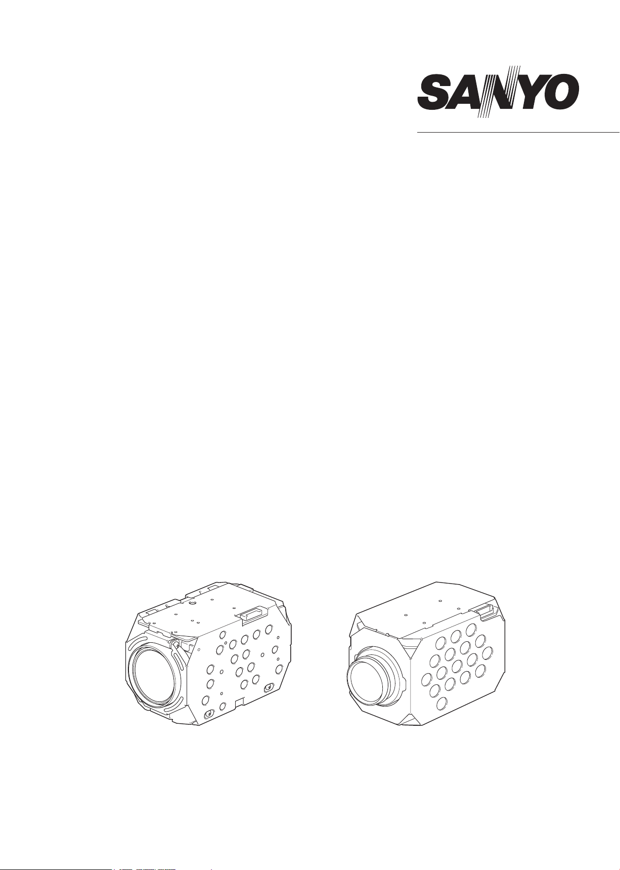
Color Camera Module
Model No.
• NTSC Model
VCC-MD800
VCC-MD700
VCC-MD600
VCC-MD500
VCC-MD400
VCC-MD300
(×36, Day/Night type)
(×36, Color type)
(×30, Day/Night type)
(×30, Color type)
(×22, Day/Night type)
(×22, Color type)
• PAL Model
VCC-MD800P
VCC-MD700P
VCC-MD600P
VCC-MD500P
VCC-MD400P
VCC-MD300P
(×36, Day/Night type)
(×36, Color type)
(×30, Day/Night type)
(×30, Color type)
(×22, Day/Night type)
(×22, Color type)
Please note that specifications and unit exterior design are subject to change without notifications.
VCC-MD500/MD500P
VCC-MD600/MD600P
VCC-MD700/MD700P
VCC-MD800/MD800P
VCC-MD400/MD400P
VCC-MD300/MD300P
(Ver 1.04)
Page 2

Contents
Parts Names and Dimensions ........ 2
Connection ....................................... 4
[1] Connection of the Interface Board and
Camera Unit .......................................................... 4
[2] Interface Board Specifications ............................... 4
Input-Output Terminal
Descriptions ..................................... 5
[1] Input-Output Terminal Layout and
Specifications ........................................................ 5
[2] FFC Compliance ................................................... 5
[3] External Synchronous Signals .............................. 5
[4] External Camera Control ....................................... 5
Communications Protocol .............. 6
[1] Communications Format ....................................... 6
Packet Format ................................................... 6
◦
Header Format ................................................... 6
◦
Terminator Format ............................................. 6
◦
Message Format ................................................ 6
◦
Checksum Format ............................................. 6
◦
Response Command Format ............................. 6
◦
[2] Communications Flow ........................................... 7
1 During Settings Command ................................ 7
2 During Query Command (Other than ACK) ...... 7
3 During Query Command (ACK) ........................ 7
[3] Command List for MD800-500 .............................. 8
[4] Command List (Query) for MD800-500 ............... 12
Function Descriptions ................... 27
[1] Zoom Control ....................................................... 27
[2] Focus Control ...................................................... 28
[3] White Balance Control ......................................... 28
[4] IRIS Control ......................................................... 29
[5] Shutter Speed Control ......................................... 29
[6] AGC Control ........................................................ 29
[7] Backlight Compensation ...................................... 30
[8] Aperture ............................................................... 31
[9] Motion Detection ................................................. 31
[10] Day/Night Switch Control................................... 31
[11] Privacy Mask Settings ....................................... 32
[12] Stabilizer ............................................................ 34
[13] Auto Pursuit Function ........................................ 35
Application Software ..................... 36
[1] Camera Control Command Transmission ........... 36
[2] Communications Error ......................................... 36
[3] RS-232C Port ...................................................... 36
[4] BAUDRATE ......................................................... 36
[5] ID SET, ID Keyboard ........................................... 36
Spectral Sensitivity
Characteristics
.............................. 37
Specifications ................................ 38
Change history .............................. 40
[5] Command List for MD400 and 300 ..................... 15
[6] Command List (Query) for MD400 and 300 ........ 19
[7] Notes ................................................................... 20
− 1 −
Page 3
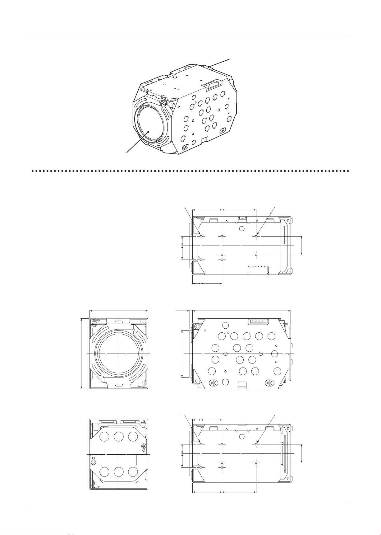
Parts Names and Dimensions
7.1
25.1 29
8
60
12
16
Ǿ40.5
(Ǿ38.6)*
18
50 843.53
(2.2)
7.1
25.1 29
812
16
18
4-M2 SCREW TAP
4-M2 SCREW TAP
3-M2 SCREW
TA P
3-M2 SCREW
TA P
Lens
CN204 terminal
VCC-MD800/700/600/500 Series
■
Dimensions
■
Note: The numbers within the brackets refer to the dimensions of the VCC-MD700 and MD800 models.
− 2 −
Page 4
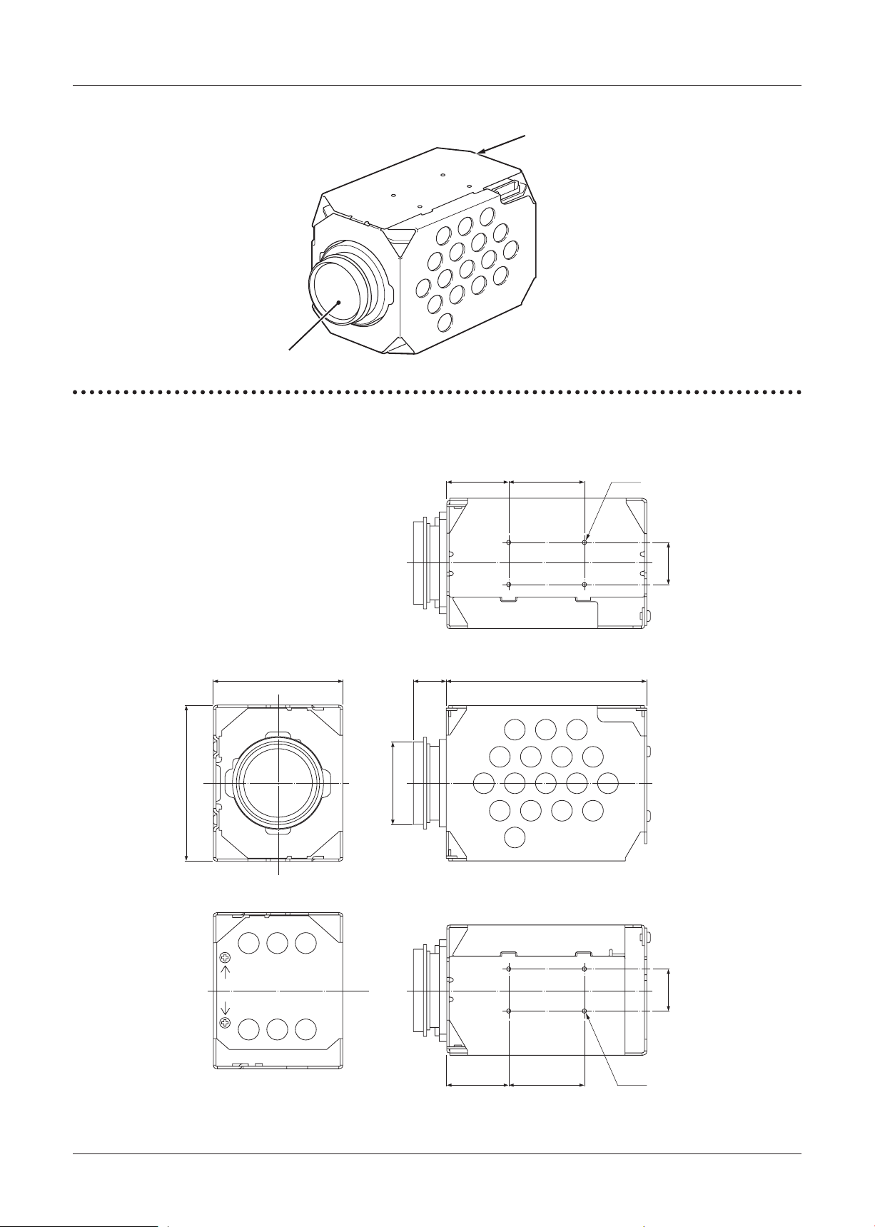
Parts Names and Dimensions
24
29
60
16
Ǿ29.7)*
Ǿ32.1
50
77
12.5
24 29
16
4-M2
4-M2
Lens
CN204 terminal: MD300
CN301 terminal: MD400
VCC-MD400/MD300 Series
■
Dimensions
■
Note: The numbers within the brackets refer to the dimensions of the VCC-MD400 model.
− 3 −
Page 5
DC12V
GND
V PULSE
GND
CN001
S0001
FFC
B
A
CN002
CN003CN004
CN005
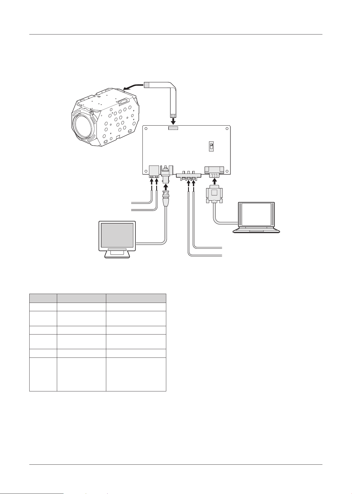
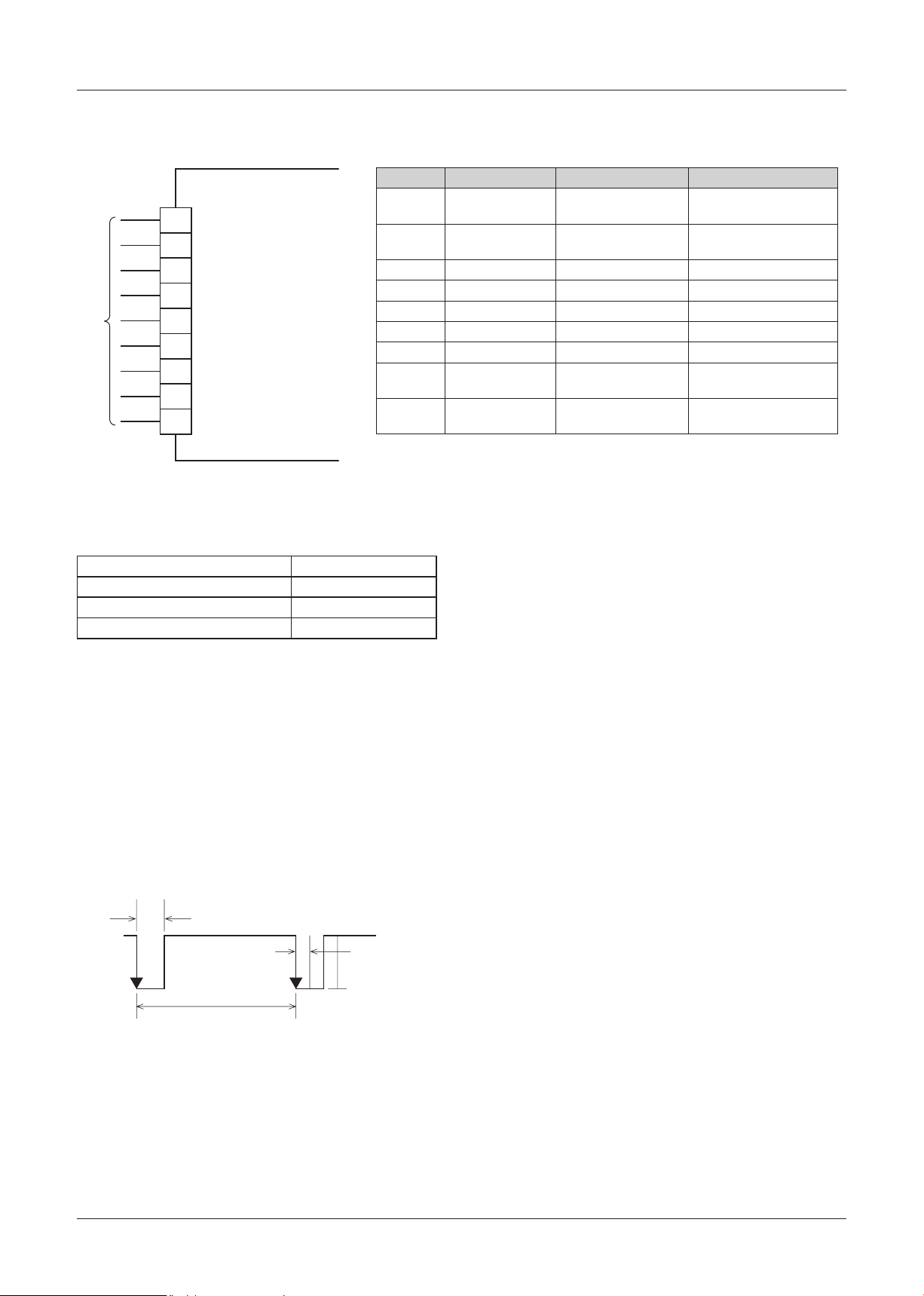
Connection
[1] Connection of the Interface Board and Camera Unit
Connect the camera unit and the interface board using the FFC (flexible flat cable). Connect the various terminals
of the interface board using the necessary cables.
[2] Interface Board Specifications
Connector
CN001 RS232C PC
CN002 Screw Power Source
CN003 BNC VIDEO OUTPUT
CN004 Push Lock V PULSE
CN005 FC Connector Camera Unit Connection
S0001
Terminal Name Details
Slide Switch
(DC12V±1V)
(External Tuning)
RS-232C Cable Type
Selection
A Side: Straight Cable
B Side: Cross (Interlink)
Cable
V PULSE
■
Input the signal of the following external tuning into
the V PULSE terminal (CN004).
Input a signal that satisfies the requirements in
[3] External Synchronous Signals 1 External
Synchronization Specifications on the following
page.
− 4 −
Page 6
Input-Output Terminal Descriptions
1 RD
2 SD
3 GND
4 DC N (+6 – 12V)
5 GND (DC)
6 VIDEO
7 GND (VIDEO)
8 LINE IN
9 GND (LINE IN)
CAMERA
FFC
LINE IN
5V
(high: min. 4.0V)
0V
(low: max. 0.8V)
60 Hz±0.25 Hz
Pulse Width: 2m-10 ms
Shaking:
Less than 50µs
[1] Input-Output Terminal Layout and Specifications
Power Supply: DC 6-12V
Pin Number
1 RD: RS-232C Communication Line
2 SD: RS-232C Communication Line
3 RD&SD GND Communication GND —
4 DC IN
5 DC IN GND Power Supply GND —
6 VIDEO OUT 75Ω C Cut Output 1.0V±0.2Vp-p
7 VIDEO OUT GND Imaging GND —
8 LINE IN External Tuning Input 60 (50: PAL) Hz ±0.25
9 LINE IN GND External
Signal Name Function I/O Signal Specifications
(Receiving)
(Transmitting)
DC Power Supply Input
Synchronization GND
Low: Max 0.8V
High: Min 2.0V
Low: Max 0.1V
High: Min 4.4V
DC +6 – 12V
Negative Synchronization
—
[2] FFC Compliance
⁃
FCI SFW9R-1STE1LF (Lead Free Product)
Core Number 9 pin
Pitch Between Conductors 1.00±0.05 mm
Length of Recommended Insulation Under 108.0±0.10 mm
Thickness of Terminal 0.30±0.05 mm
[3] External Synchronous Signals
This camera module uses external synchronization to
synchronize with the camera.
1 External Synchronization Specifications
⁃
NTSC Format: 60 Hz±0.25 (Negative
Synchronization)
⁃
PAL Format: 50 Hz±0.25 (Negative
Synchronization)
Input the LINE IN signal into the external
synchronization signal input terminal of the camera
(8 and 9 pins).
2 Internal/External Synchronization
When the power to the camera is turned on,
the external signal is input into the external
synchronization signal input terminal (8 and 9 pins).
The camera is driven by external synchronization
in the case of external synchronization (L-L). Even
if external synchronization is input, this does not
switch in the case of internal synchronization (INT).
When there is no input signal, the 8 pin is set to
Open and High:5V and is automatically set to internal
synchronization camera drive.
Note: When the camera is configured to external
synchronization (L-L), do not use the 8 pin
to fix the LowGND. This shifts the internal
synchronization frequency of the camera and
normal imaging signals cannot be emitted.
Although synchronous switching is automatic
even when switching the signal input after
turning the power on, image shaking, etc. may
occur.
[4] External Camera Control
This camera module can control the various functions
from the RS232C port of a PC, etc.
Note: Do not input signals other than LINE IN. Image
synchronization failure may occur (shaking,
jittering, etc.).
⁃
RS232C Communications Circuit
The communication interface of the camera (1, 2,
and 3 pins) is on the C-MOS level. A level shift circuit
(5Vp-p 12Vp-p) is separately required to directly
input to a PC, etc.
− 5 −
Page 7

Header
Message0Message1Message
2
…
Checksum
Te rminator
(0xFF)
Bit 7
(MSB)
Bit 6 Bit 5 Bit 4 Bit 3 Bit 2 Bit 0
(LSB)
Bit 1
1 0/1 0/1 00000
Bit 7
(MSB)
Bit 6 Bit 5 Bit 4 Bit 3 Bit 2 Bit 0
(LSB)
Bit 1
111111 11
Bit 7
(MSB)
Bit 6 Bit 5 Bit 4 Bit 3 Bit 2 Bit 0
(LSB)
Bit 1
0 0/1 0/1 0/1 0/1 0/1 0/10/1
Bit 7
(MSB)
Bit 6 Bit 5 Bit 4 Bit 3 Bit 2 Bit 0
(LSB)
Bit 1
0 0/1 0/1 0/1 0/1 0/1 0/10/1
Bit 7
(MSB)
Bit 6 Bit 5 Bit 4 Bit 3 Bit 2 Bit 0
(LSB)
Bit 1
11110/1 0/1 0/10/1
Communications Protocol
[1] Communications Format
The communication unit is a 4 (min)-24 (max) byte
packet.
・Communications Speed:
2400, 4800, 9600, 19200, 38400
9600 bps
* MD400 and MD300 cannot connect at 38400bps.
DEFAULT is 19200bps.
・
・
・
・
・
⁃
⁃
・
・
・
・
・
(DEFAULT MD800 – 500)
Data Length: 8 bit
Start Bit: 1 bit
Stop Bit: 1 bit
Parity: None
Flow Control: None
Packet Format
Header Format
Bit 0-2: Fixed [0] *Reserved bit: Camera address
(0-7)
Bit 3: Fixed [0] *Reserved bit: During broadcast
transmissions
Bit 4: Fixed [0]
Bit 5: During query commands [0], during settings
command [1]
Bit 6: During settings/query [0], during response to
query [1]
Checksum Format
⁃
Bit 0-6: Take the value that sets the lower 7 bits of
・
the values added from the header to the
checksum to 0.
Bit 7: Fixed [0]
・
Response Command Format
⁃
Bit 0-3: ACK(Ah) / NACK(Bh) / ERR(Ch)
・
Bit 4-7: Fixed [1]
・
ACK: This is the response when the process of the
・
received command is correctly completed after
receiving the data in the correct format.
NACK: This is the response when data is received in an
・
incorrect format.
ERR: Although the data is received in the correct format,
・
this is the response when the process regarding
the received command is incorrect or cannot be
conducted.
Terminator Format
⁃
Bit 0-7: Fixed [1]
・
Message Format
⁃
Bit 0-6:Refer to the various commands (0-127)
・
Bit 7: Fixed [0]
・
− 6 −
Page 8
Communications Protocol
Transmission
Source
Transmission
Destination (Unit)
Header
Message 1
Message 2
Checksum
Terminator
Response Command
Settings Command
Transmissions
Repeats the byte
count and the message
and response communications in response
to the contents of the
message.
Response Command
(NACK/ERR)
Query Command
Transmissions
Repeats the byte
count and the message
and response communications in response
to the contents of the
message.
Transmission
Source
Transmission
Destination (Unit)
Header
Message 1
Message 2
Checksum
Terminator
Response Command
(ACK)
Header
Message 1
Message 2
Checksum
Terminator
Query Command
Transmissions
Query Command
Response
Transmission
Source
Transmission
Destination (Unit)
Header
Message 1
Message 2
Checksum
Terminator
Repeats the byte
count and the message
and response communications in response
to the contents of the
message.
Repeats the byte
count and the message
and response communications in response
to the contents of the
message.
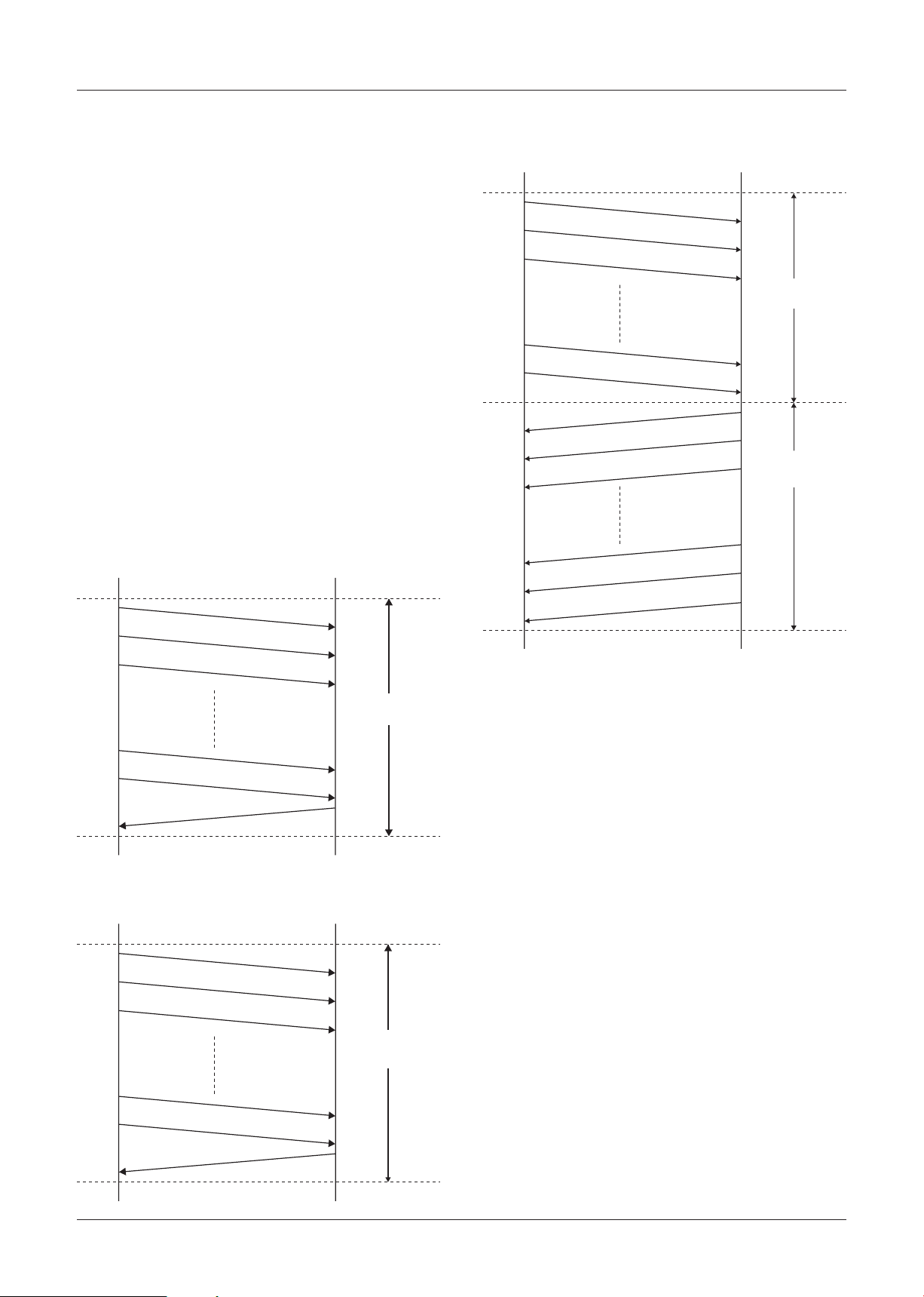
[2] Communications Flow
Note: ◦Start the transmission of the next data after
confirming the response command.
◦
MD600(P), MD500(P): 6 seconds
MD800(P), MD700(P): 9 seconds
When auto pixel defect compensation is set to
ON, below period will be added to above at
the longest.
MD600(P), MD500(P): 15seconds
MD800(P), MD700(P): 20seconds
In factory default, Auto pixel defect
compensation is set to OFF at start-up.
1 During Settings Command
The maximum transmission interval of the
◦
various byte data is 500 [msec]. If this is
exceeded, a communication error is detected
in the camera unit, the receiving data is
deleted, and data from the header is waiting
to be received again. Furthermore, there are
no special regulations regarding the minimum
value.
All the commands can be acquired after the
periods below after start-up.
3 During Query Command (ACK)
2 During Query Command (Other than ACK)
− 7 −
Page 9
Communications Protocol
Model: VCC-MD800/700/600/500
[3] Command List for MD800-500
Message
System All Initial A0 01 0A CS FF Initialization of Unadjusted EEPROM Values (Set to Factory Defaults)
Zoom Tele A0 02 05 CS FF
Focus Auto Focus ON A0 03 00 CS FF
White
Balance
Iris Auto IRIS A0 05 00 CS FF (Note 3)
CS: Checksum
FF: Terminator
All Menu Initial A0 01 0B CS FF Initialization of All Menu Settings
Lens Initial A0 01 0C CS FF Detection of initial lens position
Reset A0 01 0D CS FF Restarting camera (Saves the setting value)
Menu Initial A0 01 0E CS FF Initialization of menu settings other than privacy mask settings
Pixel defect compensation A0 01 12 00 06 04 04 06 00 Applied version 1.21-** or later (Note 8)
Auto pixel defect
compensation at start-up.
Wide A0 02 06 CS FF
Tele/Wide Stop A0 02 07 CS FF
Tele/Wide Speed A0 02 08 0p CS FF p: Speed 1-4 during Tele and Wide commands (1: Slow-4: Fast [Initial value: 3])
Direct A0 02 09 0p 0q 0r CS FF pqr: Direct Position
Zoom Direct with Focus A0 02 0A 0p 0q 0r 0s 0t 0u pqr:Zoom Direct Position stu:Focus Direct Position
Digital Zoom Tele Limiter A0 02 18 0p CS FF p: Maximum digital zoom magnification (0: x0 [Initial value], 1: x2, 2: x4, 3: x8, 4: x16)
Optical Zoom Wide/Tele
Limitter
V-Reso.UP OFF/ON A0 02 1F 0p CS FF p: Increased vertical sensitivity settings during digital zoom OFF/ON (0: OFF, 1: ON) (Note 3)
Zoom Preset ON A0 02 28 CS FF Moves the zoom position to the optical TELE edge
Zoom Preset OFF A0 02 29 CS FF Returns the zoom position to the position before the “Zoom Preset ON” operation
Manual Focus ON A0 03 01 CS FF
One Push Trigger A0 03 03 CS FF Operates the auto focus operation once
Far A0 03 05 CS FF
Near A0 03 06 CS FF
Far/Near Stop A0 03 07 CS FF
Far/Near Speed A0 03 08 0p CS FF p: Speed 1-4 during Far and Near commands (1: Slow-4: Fast (Initial value: 2))
Direct A0 03 09 0p 0q 0r CS FF pqr: Direct Position (0: Far 1209: Near)
Near Limiter A0 03 0E 0p CS FF p: Subject distance limit during auto focus and manual focus
Auto Focus Sensitivity A0 03 10 0p CS FF p: Auto focus restart sensitivity settings (0: LOW/1: HI [Initial value])
Focus Area A0 03 13 0p CS FF Settings Determining Auto Focus Areas 1-3
Cover Offset OFF/ON A0 03 15 0p CS FF p: Offset OFF/ON (0: OFF/1: ON) when using the cover
Cover Offset Level A0 03 16 0p 0q CS FF pq: Offset Level Setting 0 – 00 (Initial value: 5) when using the cover
Auto Focus Mode during pan/tilt
ATW A0 04 00 CS FF Auto White Balance Mode (Same as "0" in WB Mode)
MWB A0 04 01 CS FF Manual White Balance Mode (Same as "2" in WB Mode)
One Push Trigger (AWC Set) A0 04 03 CS FF Executes OnePush in AWC Mode
AWC Reset A0 04 04
ATW Smart OFF/ON A0 04 06 0p CS FF Smart ATW (high color saturation compensation) ON/OFF (OFF: 0 [Initial value], ON: 1)
WB Mode A0 04 07 0p CS FF p: White Balance Mode 0-5
MWB Red + A0 04 0B CS FF
MWB Red - A0 04 0C CS FF
MWB Red Preset A0 04 0F CS FF Returns MWB red component settings to factory defaults (Initial value: 64)
MWB Red Direct A0 04 13 0p 0q CS FF pq: Direct MWB red components 0-255
MWB Blue + A0 04 15 CS FF
MWB Blue - A0 04 16 CS FF
MWB Blue Preset A0 04 19 CS FF Returns MWB blue component settings to factory defaults (Initial value: 64)
MWB Blue Direct A0 04 1D 0p 0q CS FF pq: Direct MWB blue components 0-255
ATW Masking OFF A0 04 28 CS FF Mask settings ON/OFF during ATW
ATW Masking ON A0 04 29 CS FF
ATW Mask Area Clr A0 04 2D CS FF Initialization of mask settings during ATW
ATW Mask Area Set A0 04 31 0p 0q 0r 0s 0t 0u Mask area settings during ATW (Note 1)
ATW Mask Display A0 04 32 0p CS FF p: Displays the ATW MASK settings status on the monitor. (1: ON/0: OFF)
Manual IRIS (EI OFF) A0 05 01 CS FF
Manual IRIS (EI ON) A0 05 02 CS FF (Note 3)
Iris Level + A0 05 0B CS FF
Iris Level - A0 05 0C CS FF
Iris Level Preset A0 05 0F CS FF Returns iris levels during auto iris to factory defaults (Initial value: 40)
Iris Level Direct A0 05 13 0p 0q CS FF pq: Iris level 0 (Dark) - 100 (Bright) during auto iris (Initial value: 40)
Manual Iris Stop + A0 05 15 CS FF
Manual Iris Stop - A0 05 16 CS FF
Manual Iris Stop Preset A0 05 19 CS FF Returns aperture during manual iris to factory default (Initial value: 17)
Manual Iris Stop Direct A0 05 1D p CS FF p: Aperture 1 (Close) - 17 (Open) during manual iris
0C CS FF
A0 01 13 0p CS FF p: 0:OFF Default , 1:ON
CS FF
A0 02 19 xx yy CS FF Wide/Tele Optical ZOOM Limiter The numbers within the brackets refer to the MD600/500 models
A0 03 1F 0p CS FF p: Auto Focus Mode Setting during Pan/Tilt (0: AF/1: Fixed)
CS FF Returns to the original mode only after executing the OnePush Trigger command
0v 0w 0x 0y 0z 0n CS FF
Applied version 1.21-** or later
Refer to "Communications Protocol [2]Communications Flow"
※
MD800/700, 0: Wide, 2484: 36x (optical), 2724: 576x (digital)
・
MD600/500, 0: Wide, 2263: 30x (optical), 2503: 480x (digital)
・
Digital Zoom Tele Limiter command needs to be sent before moving to digital zoom field.
For carrying set the focus to the specified position.
xx: 0, 1-35 [29] (0 is no limit and 1-35 [29] is the Wide optical ZOOM limit)
yy: 0, 2-36 [30] (0 is no limit and 2-36 [30] is the Tele optical ZOOM limit)
Note: Ensure that xx < yy
(0: 10 cm, 1: 30cm, 2: 50 cm, 3: 1 m [Initial value], 4: 3 m, 5: 5 m)
1: Entire screen-3: Only center of the screen (Initial value: 2)
*This mode is valid when WB mode is set to ATW.
0: Auto White Balance, 1: AWC Mode (One-Push N/A), 2: Manual White Balance
3: 3200K Fixed Mode, 4: 5600K Fixed Mode, 5: FLUO Mode (4200K Fixed)
Iris level operation during auto iris
Aperture operation during manual iris (Initial value: 17)
− 8 −
Page 10
Communications Protocol
Model: VCC-MD800/700/600/500
Message
Backlight BLC OFF A0 06 00 CS FF Backlight compensation OFF
Shutter
Speed
Motion
Detector
CS: Checksum
FF: Terminator
Multi BLC ON A0 06 01 CS FF Backlight compensation multifractionated evaluative metering mode (Backlight compensates after
Multi BLC Weight - A0 06 04 00 CS FF Sensitivity settings during Multi BLC
Multi BLC Weight + A0 06 04 01 CS FF
Multi BLC Weight Preset A0 06 05 CS FF Returns sensitivity during Multi BLC to factory defaults (Initial value: 7)
Multi BLC Weight Direct A0 06 06 0p CS FF p: Direct sensitivity settings 0-15 during Multi BLC (Initial value: 7)
Multi BLC Bright - A0 06 07 00 CS FF Brightness settings during Multi BLC
Multi BLC Bright + A0 06 07 01 CS FF
Multi BLC Bright Preset A0 06 08 CS FF Returns brightness settings during Multi BLC to factory defaults (Initial value: 7)
Multi BLC Bright Direct A0 06 09 0p CS FF p: Direct brightness settings 0-15 during Multi BLC (Initial value: 7)
Center BLC ON A0 06 0B CS FF BLC center-weighted metering mode (Backlight compensates after measuring the light mainly in the
Center BLC Weight Preset A0 06 0F CS FF Returns sensitivity settings during Center BLC to factory defaults (Each initial value: 0)
Center BLC Weight Direct A0 06 10 0p 0q 0r 0s CS FF Sensitivity settings during Center BLC
Center BLC Area Preset A0 06 12 CS FF
Center BLC Area Direct A0 06 13 0p 0q 0r 0s CS FF Center area settings during Center BLC
Center BLC Area Display A0 06 14 0p 0q CS FF Displays the Center BLC Area settings status on the monitor. p: Display (0: OFF, 1: ON),
Mask BLC ON A0 06 15 CS FF BLC mask mode (Backlight compensates after measuring the light, ignoring areas set as mask.)
Mask BLC Area Preset A0 06 19 CS FF Return mask area settings during Mask BLC to factory defaults
Mask BLC Area Direct A0 06 1D 0p 0q 0r 0s 0t 0u Mask area settings during Mask BLC (Note 1)
0v 0w 0x 0y 0z 0n CS FF
BLC ON A0 06 33 CS FF Returns to the mode before BLC OFF only when BLC OFF
BLC Mask Display A0 06 1E 0p CS FF p: Displays the BLC MASK settings status on the monitor.(1: ON/0: OFF
Shutter Speed + A0 07 0B CS FF Increases shutter speed by one notch (Long time mode x 32 – High speed mode 1/10000) (Note 3)
Shutter Speed - A0 07 0C CS FF Decreases shutter speed by one notch (Long time mode x 32 – High speed mode 1/10000) (Note 3)
Shutter Speed Set long A0 07 0E 0p CS FF Shutter Speed Mode Settings (Note 3)
Shutter Speed OFF A0 07 0F CS FF Returns the shutter speed mode setting to normal mode setting
Shutter Long Direct A0 07 11 0p CS FF Shutter speed settings during prolonged exposure shutter mode
Shutter Short Direct A0 07 12 0p CS FF Shutter speed settings during high speed shutter mode
Sense Up + A0 07 1A CS FF Increase electronic sensitivity settings (Note 3)
Sense Up - A0 07 1B CS FF
Sense Up Direct A0 07 1D 0p CS FF p: Direct increased electronic sensitivity settings (Note 3)
ELS OFF A0 07 28 CS FF Sets shutter speed to 1x (1/60 [1/50]) after saving
ELS ON A0 07 29 CS FF Returns to electronic shutter speed saved by ELS OFF
Motion Detector OFF A0 08 00 CS FF
Motion Detector ON A0 08 01 CS FF
Motion Size Preset A0 08 05 CS FF Returns detected motion size settings to factory defaults (Initial value: V-Size: 1, H-Size: 1)
Motion Size Direct A0 08 06 0p 0q CS FF Detected motion size settings p: V-Size (1-6) q: H-Size (1-8)
Motion Size Display A0 08 07 0p CS FF p: Displays the MOTION SIZE settings status on the monitor. (1: ON/0: OFF)
Masking OFF A0 08 0A CS FF
Masking ON A0 08 0B CS FF
Mask Area Preset A0 08 0F CS FF Returns mask area for motion detection to factory defaults
Mask Area Direct A0 08 13 0p 0q 0r 0s 0t 0u Mask area settings for motion detection (Note 1)
0v 0w 0x 0y 0z 0n CS FF
Motion Mask Display A0 08 14 0p CS FF p: Displays the MOTION MASK settings status on the monitor. (1: ON/0: OFF)
Sensitivity Move + A0 08 15 CS FF
Sensitivity Move - A0 08 16 CS FF
Sensitivity Move Preset A0 08 19 CS FF Returns motion detection sensitivity settings to factory defaults (Initial value: 5)
Sensitivity Move Direct A0 08 1D 0p CS FF p: Direct motion detection sensitivity settings 1-10 (Initial value: 5)
Sensitivity Y-Level + A0 08 1F CS FF
Sensitivity Y-Level - A0 08 20 CS FF
Sensitivity Y-Level Peset A0 08 23 CS FF Returns minimum brightness settings for motion detection to factory default (Initial value: 5)
Sensitivity Y-Level Direct A0 08 27 0p CS FF p: Direct minimum brightness settings for motion detection 1-10 (Initial value: 5)
Sensitivity Y-Differ + A0 08 29 CS FF
Sensitivity Y-Differ - A0 08 2A CS FF
Sensitivity Y-Differ Preset A0 08 2D CS FF Returns brightness variation settings for undetected motion to factory defaults (Initial value: 5)
Sensitivity Y-Differ Direct A0 08 31 0p CS FF p: Direct brightness variation settings for undetected motion 1-10 (Initial value: 5)
Sensitivity Duration + A0 08 33 CS FF
Sensitivity Duration - A0 08 34 CS FF
Sensitivity Duration Preset A0 08 37 CS FF Returns continuous movement time for motion detection to factory defaults (Initial value: 1)
Sensitivity Duration Direct A0 08 3B p CS FF p: Direct continuous movement time for motion detection 1-60 (Initial value: 1)
Motion Zoom A0 08 3D 0p CS FF p: Zoom magnification during motion detection (Initial value: 0)
Motion Interval A0 08 42 0p CS FF p: Interval time until the start of next detection during motion detection (Initial value: 0)
measuring the light of the entire screen.)
BLC is easier to determine with a larger value (Initial value: 7)
Larger value increases brightness when determining BLC (Initial value: 7)
center.)
* Therefore, Center is always 7
p: Top(0-7) q: Bottom(0-7) r: Left(0-7) s: Right(0-7) (Each initial value: 0)
Returns center area settings during Center BLC to factory defaults
p: x-position(0-7) q: y-position(0-5) r: x-size(0-7) s: y-size(0-5)
(Initial value: x-position: 2 y-position: 1 x-size: 3 y-size: 3)
*When x-size:0 y-size:0, it becomes 1 area.
q: Displayed area(0: CENTER, 1: TOP, 2: BOTTOM, 3: LEFT, 4: RIGHT)
* The area that is not covered with zebra markings shows the setting area.
0: Prolonged exposure shutter mode, 1: Normal mode, 3: High speed shutter mode
(0: x1, 1: x2, 2: x4, 3: x8, 4: x16, 5: x32)
The numbers within the brackets refer to the PAL model
(0: 1/60 [1/50], 1:1/100 [1/120], 2: 1/250, 3: 1/500, 4: 1/1000, 5: 1/2000, 6: 1/4000, 7: 1/10000)
(0: OFF, 1: x2, 2: x4, 3: x8, 4: x16, 5: x32)
The numbers within the brackets refer to the PAL model
Motion sensor ON/OFF (Note 3)
1, H-Size: 1)
Mask area settings for motion detection ON/OFF
Motion detection sensitivity settings (Initial value: 5)
* Smaller values increase the sensitivity to small movements.
Minimum brightness settings for motion detection (Initial value: 5)
* Smaller values increase the sensitivity to movements even on dark screens.
Brightness variation settings for undetected motion (Initial value: 5)
* Smaller values increase the sensitivity to movements even with large brightness variation.
Continuous movement time for motion detection (Initial value: 1)
* Smaller values increase the sensitivity to fast moving subjects.
(0: OFF, 1: x1.4, 2: x2, 3: x2.8, 4: x4, 5: x5.6, 6: x 1/1.4, 7: x 1/2, 8: x 1/2.8, 9: x 1/4, 10: x 1/5.6)
(0: 5s, 1: 10s, 2: 15s, 3: 20s, 4: 30s, 5: 1m, 6: 2m, 7: 3m, 8: 4m, 9: 5m)
(Each initial value: 0)
)
VxHのMAX 9 (Initial value: V-Size:
但し、
− 9 −
Page 11
Communications Protocol
Model: VCC-MD800/700/600/500
Message
Sync Sync INT A0 09 00 CS FF Internal synchronization mode
AGC COLOR MAX Gain A0 0A 00 0p CS FF p: AGC MAX Gain settings during COLOR (0: LOW, 1: NORM, 2: MID, 3: HIGH)
Aperture OFF A0 0B 00 CS FF
Gamma OFF A0 0C 00 CS FF Gamma OFF (1)
Mirror OFF A0 0D 00 CS FF Canceling Inversions
Privacy
Masking
Pan/Tilt
Degree
STILL OFF A0 12 00 CS FF
Sync L-L A0 09 01 CS FF Power supply synchronization mode
L-L Phase + A0 09 0B CS FF
L-L Phase - A0 09 0C CS FF
L-L Phase Preset A0 09 0F CS FF Returns synchronous phase settings for power source synchronization to factory defaults
L-L Phase Direct A0 09 13 0p 0q 0r CS FF pqr: Synchronous phase settings for power source synchronization
B/W MAX Gain A0 0A 01 0p CS FF p: AGC MAX Gain settings during B/W (0: LOW, 1: NORM, 2: MID, 3: HIGH)
AUTO MAX Gain A0 0A 02 0p CS FF p: AGC MAX Gain settings during AUTO (1: NORM, 2: MID, 3: HIGH)
AGC ON/OFF A0 0A 03 0p CS FF p: AGC ON/OFF switch (Cannot be set to OFF when D/N AUTO or when SENSE UP setting is enabled)
COLOR AGC_OFF Gain + A0 0A 0B CS FF
COLOR AGC_OFF Gain - A0 0A 0C CS FF
B/W AGC_OFF Gain + A0 0A 0D CS FF
B/W AGC_OFF Gain - A0 0A 0E CS FF
Gain Preset A0 0A 0F CS FF Returns gain settings when AGC is OFF to factory defaults
Gain Direct (COLOR) A0 0A 12 0p CS FF p: Gain settings when COLOR and AGC are OFF
Gain Direct (B/W) A0 0A 13 0p CS FF p: Gain settings when B/W and AGC are OFF
ON A0 0B 01 CS FF
Aperture V + A0 0B 0B CS FF
Aperture V - A0 0B 0C CS FF
Aperture V Preset A0 0B 0F CS FF Returns vertical contour compensation settings to factory defaults (Initial value: 8)
Aperture V Direct A0 0B 13 0p CS FF p: Vertical contour compensation settings 1-15 (Initial value: 8)
Aperture H + A0 0B 15 CS FF
Aperture H - A0 0B 16 CS FF
Aperture H Preset A0 0B 19 CS FF Returns horizontal contour compensation settings to factory defaults (Initial value: 8)
Aperture H Direct A0 0B 1D 0p CS FF p: Horizontal contour compensation settings 1-15 (Initial value: 8)
ON A0 0C 01 CS FF Gamma ON (0.45)
SMART1 A0 0C 02 CS FF Gamma SMART1 (Increases the contrast of dark sections)
SMART2 A0 0C 03 CS FF Gamma SMART2 (Further increases the contrast of dark sections)
H-Mirror A0 0D 01 CS FF Horizontal inversion (Cancels vertical inversion)
V-Mirror A0 0D 02 CS FF Vertical inversion (Cancels horizontal inversion)
HV-Mirror A0 0D 03 CS FF Vertical and horizontal inversions
Area Mask OFF A0 10 00
Area Mask ON A0 10 01 0p CS FF p: Mask number 1-15 (All ON when 0) * Up to 4 masks can be displayed on a single-screen.
Privacy Mask Move A0 10 02 00 0p CS FF p: Privacy mask angle link (0: OFF, 1: ON) * When set to OFF only Mask numbers 1 – 4 can be used.
Area Mask Position Clr A0 10 05 0p CS FF p: Mask number 1-15 (ALL CLEAR when 0)
Area Mask Position Set A0 10 09 0p 0q 0r 0s 0t 0u Sets the positioning of the mask. Refer to the Privacy
Area Mask Position Center Set
Area Mask Position Full Screen
Set
Area Mask Degree Set A0 10 11 0p 0q 0r 0s xt 0u p: Mask No 1-8, qrs: Pan Degree tuv: Tilt Degree * Degree increased x10 and the value input is
Pan/Tilt Degree A0 11 00 0p 0q 0r xs 0t 0u Current positioning information settings when installing dome camera * The degree is magnified x10,
Auto Mask Pos. OFF A0 11 0A CS FF Privacy mask is set to the information of Pan/TiltDegree positioning and is not moved
Auto Mask Pos. ON A0 11 0B CS FF Privacy mask is set to the information of Pan/TiltDegree positioning and is moved
ON A0 12 01 CS FF Sets the current image to still.
0v 0w 0x CS FF
A0 10 0A 0p 0q 0r 0s 0t CS Sets the mask to the center of the optical axis. (p: mask number 1-15)
FF
A0 10 0B 0p CS FF Mask is set the full screen being displayed (p: mask number 1-15)
0v CS FF
CS FF
0p CS FF p: Mask number 1-15 (All OFF when 0)
Synchronous phase settings for power source synchronization
(Initial value: 0)
Direct 0-524 (NTSC) / 0-624 (PAL) (Initial value: 0)
(0:OFF, 1:ON) (Note 3)
Gain settings when COLOR and AGC are OFF (Initial value: 0dB)
Gain settings when B/W and AGC are OFF (Initial value: 0dB)
(D/N camera is both COLOR and B/W) (Initial value: 0dB)
(0: 0dB, 1: 3dB, 2: 6dB, 3: 9dB, 4: 12dB, 5: 15dB, 6: 18dB, 7: 21dB, 8: 24dB, 9: 27dB, 10: 30dB)
(0: 0dB, 1: 3dB, 2: 6dB, 3: 9dB, 4: 12dB, 5: 15dB, 6: 18dB, 7: 21dB, 8: 24dB, 9: 27dB, 10: 30dB)
Vertical contour compensation settings
Horizontal contour compensation settings (Initial value: 8)
*Only the "Position setting" is cleared. To make the mask display off, set the Area mask to OFF.
Refer to "Function Descriptions [11]Privacy Mask Setting"
converted to a hexadecimal number. x: Tilt angle sign bit
inputs the value changed to a hexadecimal number. pqr: Pan Degree, stu:Tilt Degree, x: Tilt angle sign
bit
(Note 9)
CS: Checksum
FF: Terminator
− 10 −
Page 12
Communications Protocol
Model: VCC-MD800/700/600/500
Message
OSD Zoom Ratio A0 14 00 0p CS FF p: Zoom magnification display
Camera IDOFF A0 15 00 CS FF Camera ID display (ON/OFF)
EEPROM
Access
Baudrate 19200 bps A0 1A 00 CS FF
ALARM ALARM OUT OFF A0 1F 00 CS FF
DAY/
NIGHT
Stabilizer Stabilizer OFF/ON A0 33 00 0p CS FF p: Stabilizer (Stabilizing function) ON/OFF (0: OFF/1: ON) * Only VCC-MD700/800 series
Auto
Pursuit
CS: Checksum
FF: Terminator
Zoom Ratio Position A0 14 01 p 0q CS FF Zoom magnification display position p: x-position (0-19) q: y-position (0-11) (Initial value: x: 19 y: 11)
Direction A0 14 02 0p CS FF p: Orientation / angle information display (1: ON/0: OFF) (Note 4)
Direction Position A0 14 03 0p 0q CS FF Positioning of the orientation / angle information display p: x-position (0-11) q: y-position (0-11) ( (Initial
Set North A0 14 04 0p CS FF p: Setting the current position to the home position (Orientation: North, PAN angle: 0˚)
Rom Version Display A0 14 10 0p CS FF p: Version display (1: ON/0: OFF) (Note 6)
ON A0 15 01 CS FF
ID SET (ASCII code) A0 15 09 p q r s t u Camera ID settings (Note 5)
ID X-Position + A0 15 0B CS FF Setting the positioning of the Camera ID display (horizontal)
ID X-Position - A0 15 0C CS FF
ID Y-Position + A0 15 10 CS FF Setting the positioning of the Camera ID display (vertical)
ID Y-Position - A0 15 11 CS FF
Title A0 15 20 0p CS FF p: Title display (1: ON/0: OFF)
Title Set (ASCII code) A0 15 21 p q r s t u Title settings (Note 5)
Title Position A0 15 22 0p CS FF p: Positioning of the title display (1: displayed on the next line from the ID / 0: displayed on the same
EEPROM Access A0 19 01 0p 0q 0r 0s 0t CS Writes the values to the EEPROM
9600 bps A0 1A 01 CS FF
4800 bps A0 1A 02 CS FF
2400 bps A0 1A 03 CS FF
38400 bps A0 1A 04 CS FF
ALARM OUT ON A0 1F 01 CS FF
LINE OUT OFF A0 1F 0A CS FF
LINE OUT ON A0 1F 0B CS FF
D/N COLOR A0 28 00 CS FF
D/N BLACK/WHITE A0 28 01 CS FF
D/N AUTO A0 28 02 CS FF
D/N BURST OFF A0 28 03 CS FF
D/N BURST ON A0 28 04 CS FF
D/N LEVEL SET A0 28 05 0p CS FF
D/N ADJ DIRECT (C->B/W) A0 28 06 0p CS FF
D/N ADJ DIRECT (B/W->C) A0 28 07 0p CS FF
D/N FOCUS SET (AUTO) A0 28 08 0p CS FF
D/N FOCUS SET (B/W) A0 28 09 0p CS FF
DNR OFF at AGC ON A0 28 14 CS FF
DNR ON at AGC ON A0 28 15 CS FF
D/N Filter Slide Time A0 28 16 p CS FF ○ p: Changes the D/N filter slide time. (5 – 20 seconds) [Initial value: 0 seconds]
Stabilizer Level A0 33 01 0p CS FF p: Setting the level of the Stabilizer Level (0: Low 1: Middle 2: High) default: 1
Auto Pursuit OFF/ON A0 34 00 0p CS FF p: Auto Pursuit ON/OFF (0: OFF/1: ON)
Auto Pursuit Sensitivity A0 34 01 0p CS FF p: Sets the sensitivity to brightness variation when motion is detected
: Only MD800/MD600 can be used.
○
v w CS FF
v w CS FF
FF
value: x: 1 y: 11
(1: ON/0: PRESET) (Note 4)
line)
pqr: Address 0-2047 st: Data 0-255
UART communication speed settings
Enables after camera restart
External alarm output settings (For zoom cameras)
Alarm output settings to controller (For zoom cameras)
Color Mode
○
Black and White Mode
○
Color/Black and White Auto Switch Mode (Note 3)
○
○
Burst Settings ON/OFF
○
p: Color/Black and White Switch Level Settings (0: LOW, 1: MID, 2: HIGH, 3: ADJ)
○
Switch level LOW: Dark – High: Bright ADJ: Manual setting
Switch Level LOW: Dark-HIGH: Bright
○
ADJ: Manual Settings
p: Color Black and White Switch Level Manual Settings 0-6
Larger value switches darker sections (Initial value: 4)
p: Black and White Color Switch Level Manual Settings 0-6
○
Larger value switches darker sections (Initial value: 4)
p: Focus mode settings during D/N AUTO black and white, 0: Near infrared wavelength compensation
○
(MODE1), 1: Corresponds to optical wavelengths (MODE2)
p: Focus mode settings during D/N BLACK/WHITE, 0: Near infrared wavelength compensation
○
(MODE1), 1: Corresponds to optical wavelengths (MODE2)
DNR ON/OFF (Note 3)
* Only VCC-MD700/800 series
1-F (High sensitivity – Low sensitivity)
)
− 11 −
Page 13
Communications Protocol
Model: VCC-MD800/700/600/500
100
~
p: 0:OFF, 1:ON
pq: 0
Offset ON/OFF setting when using the cover
Offset level setting when using the cover
CS FF
80 02 18 CS FF C0 02 18 0p CS FF Current Digital Zoom Limit
Auto Focus Sensitivity 80 03 10 CS FF C0 03 10 0p CS FF
Near Limiter 80 03 0E CS FF C0 03 0E 0p CS FF
Direct 80 02 09 CS FF C0 02 09 0p 0q 0r CS FF Current Zoom Lens Position Direct Position 0:Wide 2263:Tele
Message Query Command Response Command
Zoom Tele/Wide Speed 80 02 08 CS FF C0 02 08 0p CS FF Configured Tele/Wide Speed 1: speed1, 2: speed2, 3: speed3, 4: speed4
[4] Command List (Query) for MD800-500
Direct 80 03 09 CS FF C0 03 09 0p 0q 0r CS FF Current Focus Lens Position Direct Position 0:Far 1209:Near
V-Reso.UP OFF/ON 80 02 1F CS FF C0 02 1F 0p CS FF
Digital Zoom Tele Limiter
Focus Far/Near Speed 80 03 08 CS FF C0 03 08 0p CS FF Configured Far/Near Speed 1: speed1, 2: speed2, 3: speed3, 4: speed4
80 03 1F CS FF C0 03 1F 0p CS FF Auto focus mode setting during Pan/Tilt p: 0:AF, 1: Fixed
Cover Offset OFF/ON 80 03 15 CS FF C0 03 15 0p CS FF
Focus Area 80 03 13 CS FF C0 03 13 0p CS FF
Auto Focus Mode during
pan/tilt
Cover Offset Level 80 03 16 CS FF C0 03 16 0p 0q CS FF
WB Mode 80 04 07 CS FF C0 04 07 0p CS FF
ATW Smart OFF/ON 80 04 06 CS FF C0 04 06 0p CS FF
MWB Blue Direct 80 04 1D CS FF C0 04 1D 0p 0q CS FF MWB B Component Set Value Direct 0-255
MWB Red Direct 80 04 13 CS FF C0 04 13 0p 0q CS FF MWB R Component Set Value Direct 0-255
White
Balance
Multi BLC Bright Direct 80 06 09 CS FF C0 06 09 0p CS FF
Iris Stop Direct 80 05 1D CS FF C0 05 1D p CS FF Iris Aperture Set Value 1-17
Blc Multi BLC Weight Direct 80 06 06 CS FF C0 06 06 0p CS FF
Iris Iris Level Direct 80 05 13 CS FF C0 05 13 0p 0q CS FF Iris Level Set Value Direct 0-100
80 06 10 CS FF C0 06 10 0p 0q 0r 0s CS FF
80 07 0E CS FF C0 07 0E 0p CS FF
Sensitivity Move Direct 80 08 1D CS FF C0 08 1D 0p CS FF
Sense Up Direct 80 07 1D CS FF C0 07 1D 0p CS FF
Shutter Short Direct 80 07 12 CS FF C0 07 12 0p CS FF
Center BLC Area Direct 80 06 13 CS FF C0 06 13 0p 0q 0r 0s
Shutter Long Direct 80 07 11 CS FF C0 07 11 0p CS FF
Center BLC Weight Direct
Shutter Speed Set Mode
Shutter
Motion Motion Size Direct 80 08 06 CS FF C0 08 06 0p 0q CS FF
− 12 −
80 08 27 CS FF C0 08 27 0p CS FF
80 08 31 CS FF C0 08 31 0p CS FF
80 08 3B CS FF C0 08 3B 0p CS FF
Motion Interval 80 08 42 CS FF C0 08 42 0p CS FF
Motion Zoom 80 08 3D CS FF C0 08 3D 0p CS FF
Sensitivity Y-Level Direct
Sensitivity Y-Differ Direct
Sensitivity Duration Direct
CS: Checksum
FF: Terminator
Page 14

Communications Protocol
Model: VCC-MD800/700/600/500
)
pq×0.3dB
(
1-15
"0: 0dB, 1: 3dB, 2: 6dB, 3: 9dB, 4: 12dB,
"0: 0dB, 1: 3dB, 2: 6dB, 3: 9dB, 4: 12dB,
5: 15dB, 6: 18dB, 7: 21dB, 8: 24dB,
p: 1: NORM, 2: MID, 3: HIGH
p: 0:LOW, 1: NORM, 2: MID, 3: HIGH
p: 0:LOW, 1: NORM, 2: MID, 3: HIGH
9: 27dB, 10: 30dB"
1-15
5: 15dB, 6: 18dB, 7: 21dB, 8: 24dB,
9: 27dB, 10: 30dB"
Refer to "Function Descriptions [11]
p: x-position (0-11) q: y-position (0-11)
p: x-position (0-19) q: y-position (0-11)
p: 0:OFF, 1:H-Mirror, 2:V-Mirror, 3:HV-Mirror
Privacy Mask Setting"
pq: x-coordinate rs: y-coordinate
Refer to "Function Descriptions [11]Privacy
Mask Setting"
OFF
are OFF
AUTO
(D/N camera set value when in COLOR)
Value
Value
display
information display
C0 15 20 0p CS FF Title display 0: OFF/1: ON
on the privacy mask coordinates
Privacy Mask Position Refer to the Privacy Mask Settings (P29)
C0 10 09 0p 0q 0r 0s 0t 0u 0v 0w 0x CS FF
80 0A 15 CS FF C0 0A 15 0p 0q CS FF Current Gain Value (AGC ON) pq: 0-120
80 0A 14 CS FF C0 0A 14 0p CS FF Gain Settings when B/W and AGC are
80 0A 13 CS FF C0 0A 13 0p CS FF Gain Settings when COLOR and AGC
80 0A 0B CS FF C0 0A 0B 0p CS FF AGC MAX Gain Set Value during
80 0A 09 CS FF C0 0A 09 0p CS FF AGC MAX Gain Set Value
)
BW) 80 0A 0A CS FF C0 0A 0A 0p CS FF AGC MAX Gain Set Value during B/W
(
COLOR
)
COLOR
(
AGC Max Gain at AGC
Message Query Command Response Command
Sync L-L Phase Direct 80 09 13 CS FF C0 09 13 0p 0q 0r CS FF Power Source Synchronous Set Value Direct 0-524(NTSC) / 0-624(PAL)
(
AUTO)
Gain Direct
Max Gain at AGC
Max Gain at AGC
(
)
)
AGC ON
BW
(
(
Gain Direct
Gain Direct
Aperture Aperture V Direct 80 0B 13 CS FF C0 0B 13 00 0p CS FF Vertical Contour Compensation Set
Aperture H Direct 80 0B 1D CS FF C0 0B 1D 00 0p CS FF Horizontal Contour Compensation Set
Mirror Mode 80 0D CS FF C0 0D 0p CS FF
Gamma Mode 80 0C CS FF C0 0C 0p CS FF p: 0:1, 1:0.45, 2:SMART1, 3:SMART2
OSD Zoom Ratio 80 14 00 CS FF C0 14 00 0p CS FF Zoom magnification display 0: OFF/1: ON
Direction Position 80 14 03 CS FF C0 14 03 0p 0q CS FF Positioning of the orientation / angle
Direction 80 14 02 CS FF C0 14 02 0p CS FF Orientation / angle information display 0: OFF/1: ON
Zoom Ratio Position 80 14 01 CS FF C0 14 01 p 0q CS FF Positioning of the zoom magnification
Title 80 15 20 CS FF
Set North 80 14 04 CS FF C0 14 04 0p CS FF Angle settings 0: not set / 1: set
Camera ID ID Code 80 15 09 CS FF C0 15 09 p q r s t u v w CS FF ASCII code for the camera ID (Note 5)
− 13 −
80 10 12 CS FF C0 10 12 0p 0q 0r 0s CS FF Coordinates of the central optical axis
Mask Area Center
Masking
Position
View Setting View Setting No 80 18 01 CS FF C0 18 01 0p CS FF Current Display View Angle File No.
Mask Position 80 10 09 0p CS FF
Title Position 80 15 22 CS FF C0 15 22 0p CS FF Positioning of the title display 1: 2 line display / 0: 1 line display
Title Code 80 15 21 CS FF C0 15 21 p q r s t u v w CS FF ASCII code for the title (Note 5)
Privacy
EEPROM Access 80 19 01 0p 0q 0r CS FF C0 19 01 0s 0t CS FF Value Written to EEPROM pqr: Address 0-2047 st: Data 0-255
EEPROM
Access
CS: Checksum
FF: Terminator
Page 15

Communications Protocol
Model: VCC-MD800/700/600/500
* Only VCC-MD700/800 series
0: MODE1, 1: MODE2
0: MODE1, 1: MODE2
0-6
0-6
0: LOW, 1: MID, 2: HIGH, 3: ADJ
* Only VCC-MD700/800 series
Movement direction (lateral) (1:Right/2:Left)
p: 1-F High sensitivity – Low sensitivity
Movement direction (vertical) (1:Up/2:Down)
q:
rs: Lateral movement distance (%)
tu: Vertical movement distance (%)
Manual Set Value
Set Value
and White
AUTO Black and White
Manual Set Value
time of motion detection
CS FF
80 28 08 CS FF C0 28 08 0p CS FF Focus Mode Set Value during D/N
80 28 07 CS FF C0 28 07 0p CS FF Black and White Color Switch Level
80 28 06 CS FF C0 28 06 0p CS FF Color Black and White Switch Level
Stabilizer Level 80 33 01 CS FF C0 33 01 0p CS FF Stabilizer Level p: 0:Low/1:Middle/2:High
D/N Filter Slide Time 80 28 0A CS FF C0 28 0A p CS FF D/N filter slide time. p: 5 – 20 seconds
D/N FOCUS SET (B/W) 80 28 09 CS FF C0 28 09 0p CS FF Focus Mode Set Value during Black
D/N FOCUS SET
(AUTO)
D/N ADJ DIRECT (B/
W->C)
D/N ADJ DIRECT
(C->B/W)
Message Query Command Response Command
DAY/NIGHT D/N LEVEL 80 28 05 CS FF C0 28 05 0p CS FF Color/Black and White Switch Level
Stabilizer Stabilizer ON/OFF 80 33 00 CS FF C0 33 00 0p CS FF Stabilizer ON/OFF p: 0:OFF/1:ON
Status type 7 80 4A 07 CS FF C0 4A 07 0p 0q 0r 0s 0t 0u CS FF Movement distance for auto pursuit p:
Status type 6 80 4A 06 CS FF C0 4A 06 0p CS FF (Note 2)
Status type 5 80 4A 05 CS FF C0 4A 05 p q r s t CS FF (Note 2)
Status type 4 80 4A 04 CS FF C0 4A 04 p q r s t u v w CS FF (Note 2)
Status type 3 80 4A 03 CS FF C0 4A 03 p q r s t u CS FF (Note 2)
Status type 2 80 4A 02 CS FF C0 4A 02 p q r s t u v w x y CS FF (Note 2)
Auto Pursuit Sensitivity 80 34 01 CS FF C0 34 01 0p CS FF Sensitivity to brightness variation at the
Status Status 80 4A 01 CS FF C0 4A 01 p q r s t u CS FF (Note 2)
Auto Pursuit Auto Pursuit OFF/ON 80 34 00 CS FF C0 34 00 0p CS FF Auto Pursuit ON/OFF p: 0:OFF/1:ON
− 14 −
Status type 8 80 4A 08 CS FF C0 4A 08 0p 0q 0r 0s 0t 0u 0v 0w 0x 0y 0z 0n Motion Detection Area (Note 1)
4A 0A CS FF C0 4A 0A 0p 0q 0r 0s 0t 0u 0v 0w CS FF p-w: Version
Rom Version 80
CS: Checksum
FF: Terminator
Page 16
Communications Protocol
Model: VCC-MD400/300
[5] Command List for MD400 and 300
Message
System CAMERA TYPE Unit A0 01 01 00 CS FF
Zoom Tele A0 02 05 CS FF
Focus Auto Focus ON A0 03 00 CS FF
White
Balance
Iris Auto IRIS A0 05 00 CS FF
CAMERA TYPE Dome A0 01 01 01 CS FF Sanyo Dome Camera ID
CAMERA TYPE Zoom A0 01 01 02 CS FF Sanyo Dome Camera ID
All Initial A0 01 0A CS FF Initialization of Unadjusted EEPROM Values (Set to Factory Defaults)
All Menu Initial A0 01 0B CS FF Initialization of All Menu Settings
Lens Initial A0 01 0C CS FF Detection of initial lens position
Reset A0 01 0D CS FF Restarting camera (Saves the setting value)
Menu Initial A0 01 0E CS FF Initialization of menu settings other than privacy mask settings
Wide A0 02 06 CS FF
Tele/Wide Stop A0 02 07 CS FF
Tele/Wide Speed A0 02 08 0p CS FF p: Speed 1-4 during Tele and Wide commands (1: Slow-4: Fast [Initial value: 3])
Direct A0 02 09 0p 0q 0r CS FF pqr: Direct Position
Digital Zoom Tele Limiter A0 02 18 0p CS FF p: Maximum digital zoom magnification (0: x0 [Initial value], 1: x2, 2: x4, 3: x8, 4: x16)
V-Reso.UP OFF/ON A0 02 1F 0p CS FF p: Increased vertical sensitivity settings during digital zoom OFF/ON (0: OFF, 1: ON)
VIEW ANGLE Set *1 A0 02 23 0p CS FF p: Vignette Reduction Mode Settings (0: OFF, 1: OVER0・1.05x, 2: OVER1・1.06x,
Zoom Preset ON A0 02 28 CS FF Moves the zoom position to the optical TELE edge
Zoom Preset OFF A0 02 29 CS FF Returns the zoom position to the position before the “Zoom Preset ON” operation
Manual Focus ON A0 03 01 CS FF
One Push Trigger A0 03 03 CS FF Operates the auto focus operation once
Far A0 03 05 CS FF
Near A0 03 06 CS FF
Far/Near Stop A0 03 07 CS FF
Far/Near Speed A0 03 08 0p CS FF p: Speed 1-4 during Far and Near commands (1: Slow-4: Fast (Initial value: 2))
Direct A0 03 09 0p 0q 0r CS FF pqr: Direct Position (VCC-MD400 0:Far 3524:Near VCC-MD300 0:Far 4008:Near)
Near Limiter A0 03 0E 0p CS FF p: Subject distance limit during auto focus and manual focus
Auto Focus Sensitivity A0 03 10 0p CS FF p: Auto focus restart sensitivity settings (0: LOW, 1: HI [Initial value], 2: HI+)
Focus Area A0 03 13 0p CS FF Settings Determining Auto Focus Areas 1-3
ATW A0 04 00 CS FF Auto White Balance Mode (Same as "0" in WB Mode)
MWB A0 04 01 CS FF Manual White Balance Mode (Same as "1" in WB Mode)
One Push Trigger (AWC Set) A0 04 03 CS FF Executes OnePush in AWC Mode (Note 7)
AWC Reset A0 04 04 CS FF Returns to the original mode only after executing the OnePush Trigger command
ATW Smart OFF/ON A0 04 06 0p CS FF Smart ATW (high color saturation compensation) ON/OFF (OFF: 0 [Initial value], ON: 1) (Note 7)
MWB Red + A0 04 0B CS FF
MWB Red - A0 04 0C CS
MWB Red Preset A0 04 0F CS FF Returns MWB red component settings to factory defaults (Initial value: 64)
MWB Red Direct A0 04 13 0p 0q CS FF pq: Direct MWB red components 0-255
MWB Blue + A0 04 15 CS FF
MWB Blue - A0 04 16 CS FF
MWB Blue Preset A0 04 19 CS FF Returns MWB blue component settings to factory defaults (Initial value: 64)
MWB Blue Direct A0 04 1D 0p 0q CS FF pq: Direct MWB blue components 0-255
ATW Masking OFF A0 04 28 CS FF Mask settings ON/OFF during ATW
ATW Masking ON A0 04 29 CS FF
ATW Mask Area Clr A0 04 2D CS FF Initialization of mask settings during ATW
ATW Mask Area Set A0 04 31 0p 0q 0r 0s 0t 0u Mask area settings during ATW (Note 1)
0v 0w 0x 0y 0z 0n CS FF
Manual IRIS (EI OFF) A0 05 01 CS FF
Manual IRIS (EI ON) A0 05 02 CS FF
Iris Level + A0 05 0B CS FF
Iris Level - A0 05 0C CS FF
Iris Level Preset A0 05 0F CS FF Returns iris levels during auto iris to factory defaults (Initial value: 40)
Iris Level Direct A0 05 13 0p 0q CS FF pq: Iris level 0 (Dark) - 100 (Bright) during auto iris (Initial value: 40)
Manual Iris Stop + A0 05 15 CS FF
Manual Iris Stop - A0 05 16 CS FF
Manual Iris Stop Preset A0 05 19 CS FF Returns aperture during manual iris to factory default (Initial value: 17)
Manual Iris Stop Direct A0 05 1D 0p CS FF p: Aperture 1 (Close) - 17 (Open) during manual iris
FF
MD400, 0: Wide, 1829: 22x (optical), 2069: 352x (digital)
・
MD300, 0: Wide, 2248: 22x (optical), 2488: 352x (digital)
・
Digital Zoom Tele Limiter command needs to be sent before moving to digital zoom field.
3: OVER 2・1.07x, 4: OVER 3・1.08x, 5: OVER4・1.09x, 6: OVER5・1.10x) (Initial value: 0)
(0: 10 cm, 1: 30cm, 2: 50 cm, 3: 1 m [Initial value], 4: 3 m, 5: 5 m)
High+ automatically restarts every 10 seconds (only TELE side) in addition to restarting the change in
subject
1: Entire screen-3: Only center of the screen (Initial value: 2)
*This mode is valid when WB mode is set to ATW.
Iris level operation during auto iris
Aperture operation during manual iris (Initial value: 17)
*1: Only MD400 CS: Checksum
*2: Only MD300 FF: Terminator
− 15 −
Page 17

Communications Protocol
Model: VCC-MD400/300
Message
Backlight BLC OFF A0 06 00 CS FF Backlight compensation OFF
Shutter
Speed
Motion
Detector
Sync Sync INT A0 09 00 CS FF Internal synchronization mode
Multi BLC ON A0 06 01 CS FF Backlight compensation multifractionated evaluative metering mode (Backlight compensates after
Multi BLC Weight - A0 06 04 00 CS FF Sensitivity settings during Multi BLC
Multi BLC Weight + A0 06 04 01 CS FF
Multi BLC Weight Preset A0 06 05 CS FF Returns sensitivity during Multi BLC to factory defaults (Initial value: 7)
Multi BLC Weight Direct A0 06 06 0p CS FF p: Direct sensitivity settings 0-15 during Multi BLC (Initial value: 7)
Multi BLC Bright - A0 06 07 00 CS FF Brightness settings during Multi BLC
Multi BLC Bright + A0 06 07 01 CS FF
Multi BLC Bright Preset A0 06 08 CS FF Returns brightness settings during Multi BLC to factory defaults (Initial value: 7)
Multi BLC Bright Direct A0 06 09 0p CS FF p: Direct brightness settings 0-15 during Multi BLC (Initial value: 7)
Center BLC ON A0 06 0B CS FF BLC center-weighted metering mode (Backlight compensates after measuring the light mainly in the
Center BLC Weight Preset A0 06 0F CS FF Returns sensitivity settings during Center BLC to factory defaults (Each initial value: 0)
Center BLC Weight Direct A0 06 10 0p 0q 0r 0s CS FF Sensitivity settings during Center BLC
Center BLC Area Preset A0 06 12 CS FF
Center BLC Area Direct A0 06 13 0p 0q 0r 0s CS FF Center area settings during Center BLC
Mask BLC ON A0 06 15 CS FF BLC mask mode
Mask BLC Area Preset A0 06 19 CS FF Return mask area settings during Mask BLC to factory defaults
Mask BLC Area Direct A0 06 1D 0p 0q 0r 0s 0t 0u Mask area settings during Mask BLC (Note 1)
0v 0w 0x 0y 0z 0n CS FF
BLC ON A0 06 33 CS FF Returns to the mode before BLC OFF only when BLC OFF
Shutter Speed + A0 07 0B CS FF Increases shutter speed by one notch
Shutter Speed - A0 07 0C CS FF Decreases shutter speed by one notch
Shutter Speed Set long A0 07 0E 0p CS FF Shutter Speed Mode Settings
Shutter Speed OFF A0 07 0F CS FF Same as Shutter Speed Set OFF
Shutter Long Direct A0 07 11 0p CS FF Shutter speed settings during prolonged exposure shutter mode
Shutter Short Direct A0 07 12 0p CS FF Shutter speed settings during high speed shutter mode
Sense Up + A0 07 1A CS FF Increase electronic sensitivity settings
Sense Up - A0 07 1B CS FF
Sense Up Direct A0 07 1D 0p CS FF p: Direct increased electronic sensitivity settings
ELS OFF A0 07 28 CS FF Sets shutter speed to 1x (1/60) after saving
ELS ON A0 07 29 CS FF Returns to electronic shutter speed saved by ELS OFF
Motion Detector OFF A0 08 00 CS FF
Motion Detector ON A0 08 01 CS FF
Motion Size Preset A0 08 05 CS FF Returns detected motion size settings to factory defaults (Initial value: V-Size: 1, H-Size: 1)
Motion Size Direct A0 08 06 0p 0q CS FF Detected motion size settings p: V-Size (1-6) q: H-Size (1-8) (Initial value: V-Size: 1, H-Size: 1)
Alarm Sign OFF A0 08 08 CS FF
Alarm Sign ON A0 08 09 CS FF
Masking OFF A0 08 0A CS FF
Masking ON A0 08 0B CS FF
Mask Area Preset A0 08 0F CS FF Returns mask area for motion detection to factory defaults
Mask Area Direct A0 08 13 0p 0q 0r 0s 0t 0u Mask area settings for motion detection (Note 1)
0v 0w 0x 0y 0z 0n CS FF
Sensitivity Move + A0 08 15 CS FF
Sensitivity Move - A0 08 16 CS FF
Sensitivity Move Preset A0 08 19 CS FF Returns motion detection sensitivity settings to factory defaults (Initial value: 5)
Sensitivity Move Direct A0 08 1D 0p CS FF p: Direct motion detection sensitivity settings 1-10 (Initial value: 5)
Sensitivity Y-Level + A0 08 1F CS FF
Sensitivity Y-Level - A0 08 20 CS FF
Sensitivity Y-Level Peset A0 08 23 CS FF Returns minimum brightness settings for motion detection to factory default (Initial value: 5)
Sensitivity Y-Level Direct A0 08 27 0p CS FF p: Direct minimum brightness settings for motion detection 1-10 (Initial value: 5)
Sensitivity Y-Differ + A0 08 29 CS FF
Sensitivity Y-Differ - A0 08 2A CS FF
Sensitivity Y-Differ Preset A0 08 2D CS FF Returns brightness variation settings for undetected motion to factory defaults (Initial value: 5)
Sensitivity Y-Differ Direct A0 08 31 0p CS FF p: Direct brightness variation settings for undetected motion 1-10 (Initial value: 5)
Sensitivity Duration + A0 08 33 CS FF
Sensitivity Duration - A0 08 34 CS FF
Sensitivity Duration Preset A0 08 37 CS FF Returns continuous movement time for motion detection to factory defaults (Initial value: 1)
Sensitivity Duration Direct A0 08 3B 0p CS FF p: Direct continuous movement time for motion detection 1-60 (Initial value: 1)
Motion Zoom A0 08 3D 0p CS FF p: Zoom magnification during motion detection
Motion Interval A0 08 42 0p CS FF p: Interval time until the start of next detection during motion detection
Sync L-L A0 09 01 CS FF Power supply synchronization mode
L-L Phase + A0 09 0B CS FF
L-L Phase - A0 09 0C CS FF
L-L Phase Preset A0 09 0F CS FF Returns synchronous phase settings for power source synchronization to factory defaults
L-L Phase Direct A0 09 13 0p 0q 0r CS FF pqr: Synchronous phase settings for power source synchronization
measuring the light of the entire screen.)
BLC is easier to determine with a larger value (Initial value: 7)
Larger value increases brightness when determining BLC (Initial value: 7)
center.)
p: Top(0-7) q: Bottom(0-7) r: Left(0-7) s: Right(0-7) (Each initial value: 0)
Returns center area settings during Center BLC to factory defaults
p: x-position(0-7) q: y-position(0-5) r: x-size(0-7) s: y-size(0-5)
(Initial value: x-position: 2 y-position: 1 x-size: 3 y-size: 3)
*When x-size:0 y-size:0, it becomes 1 area.
0: Prolonged exposure shutter mode, 1: Normal mode, 3: High speed shutter mode
(0: x1, 1: x2, 2: x4, 3: x8, 4: x16, 5: x32)
(0: 1/60 (50), 1:1/100 (120), 2: 1/250, 3: 1/500, 4: 1/1000, 5: 1/2000, 6: 1/4000, 7: 1/10000)
(0: OFF, 1: x2, 2: x4, 3: x8, 4: x16, 5: x32)
Motion sensor ON/OFF
Display ON/OFF during alarm input
Mask area settings for motion detection ON/OFF
Motion detection sensitivity settings (Initial value: 5)
Minimum brightness settings for motion detection (Initial value: 5)
Brightness variation settings for undetected motion (Initial value: 5)
Continuous movement time for motion detection (Initial value: 1)
(0: OFF, 1: x1.4, 2: x2, 3: x2.8, 4: x4, 5: x6)
(0: 5s, 1: 10s, 2: 15s, 3: 20s, 4: 30s, 5: 1m, 6: 2m, 7: 3m, 8: 4m, 9: 5m)
Synchronous phase settings for power source synchronization
(Initial value: 0)
Direct 0-524 (NTSC) / 0-624 (PAL) (Each initial value: 0)
(Each initial value: 0)
*1: Only MD400 CS: Checksum
*2: Only MD300 FF: Terminator
− 16 −
Page 18

Communications Protocol
Model: VCC-MD400/300
Message
Camera IDOFF A0 15 00 CS FF Camera ID display
AGC COLOR MAX Gain *1 A0 0A 00 0p CS FF AGC MAX Gain settings during COLOR (0:AGC OFF, 1: -6dB, 2: 0dB, 3: 6dB, 4: 9dB)
Aperture OFF A0 0B 00 CS FF
Gamma OFF A0 0C 00 CS FF Gamma OFF (1)
Mirror OFF A0 0D 00 CS FF Canceling Inversions
Privacy
Masking
Pan/Tilt
Degree
STILL OFF A0 12 00 CS FF
EEPROM
Access
Baudrate 19200 bps A0 1A 00 CS FF
ON A0 15 01 CS FF
ID SET (ASCII code) A0 15 09 p q r s t Camera ID settings (Note 5)
ID X-Position + A0 15 0B CS FF Setting the positioning of the Camera ID display (horizontal)
ID X-Position - A0 15 0C CS FF
ID Y-Position + A0 15 10 CS FF Setting the positioning of the Camera ID display (vertical)
ID Y-Position - A0 15 11 CS FF
B/W MAX Gain *1 A0 0A 01 0p CS FF AGC MAX Gain settings during B/W (0:AGC OFF, 1: -6dB, 2: 0dB, 3: 6dB, 4: 9dB, 5:12dB, 6:15dB)
AUTO MAX Gain *1 A0 0A 02 0p CS FF AGC MAX Gain settings during AUTO (4: 9dB, 5:12dB, 6:15dB)
AGC ON/OFF *2 A0 0A 03 0p CS FF AGC ON/OFF switch (invalid during D/N AUTO) (0:OFF, 1:ON)
Max Gain at AGC ON *2 A0 0A 09 0p CS FF AGC MAX Gain settings during AUTO (0: -6dB, 1: 0dB, 2: 6dB, 3: 9dB)
COLOR AGC_OFF Gain + A0 0A 0B CS FF
COLOR AGC_OFF Gain - A0 0A 0C CS FF
B/W AGC_OFF Gain + *1 A0 0A 0D CS FF
B/W AGC_OFF Gain - *1 A0 0A 0E CS FF
Gain Preset A0 0A 0F CS FF Returns gain settings when AGC is OFF to factory defaults
Gain Direct (COLOR) *1 A0 0A 12 0p CS FF Gain settings when COLOR and AGC are OFF
Gain Direct (B/W) *1 A0 0A 13 0p CS FF Gain settings when B/W and AGC are OFF
Gain Direct *2 A0 0A 13 0 CS FF Gain setting when AGC is OFF
DNR OFF at AGC ON *2 A0 0A 14 CS FF DNR ON/OFF
DNR ON at AGC ON *2 A0 0A 15 CS FF
ON A0 0B 01 CS FF
Aperture V + A0 0B 0B CS FF
Aperture V - A0 0B 0C CS FF
Aperture V Preset A0 0B 0F CS FF Returns vertical contour compensation settings to factory defaults (Initial value: 8)
Aperture V Direct A0 0B 13 0p CS FF p: Vertical contour compensation settings 1-15 (Initial value: 8)
Aperture H + A0 0B 15 CS FF
Aperture H - A0 0B 16 CS FF
Aperture H Preset A0 0B 19 CS FF Returns horizontal contour compensation settings to factory defaults (Initial value: 8)
Aperture H Direct A0 0B 1D 0p CS FF p: Horizontal contour compensation settings 1-15 (Initial value: 8)
ON A0 0C 01 CS FF Gamma ON (0.45)
SMART1 A0 0C 02 CS FF Gamma SMART1 (Increases the contrast of dark sections)
SMART2 A0 0C 03 CS FF Gamma SMART2 (Further increases the contrast of dark sections)
H-Mirror A0 0D 01 CS FF Horizontal inversion (Cancels vertical inversion)
V-Mirror A0 0D 02 CS
HV-Mirror A0 0D 03 CS FF Vertical and horizontal inversions
Area Mask OFF A0 10 00 0p CS FF p: Mask number 1-8 (ALL OFF when 0)
Area Mask ON A0 10 01 0p CS FF p: Mask number 1-8 (ALL ON when 0)
Area Mask Position Clr A0 10 05 0p CS FF p: Mask number 1-8 (ALL CLEAR when 0)
Area Mask Position Set A0 10 09 0p 0q 0r 0s 0t 0u Refer to "Function Descriptions [11]Privacy Mask Setting"
Area Mask Position Center Set
Mask Area Degree Set *2 A0 10 11 0p 0q 0r 0s 0t 0u p: Mask No 1-8, qrs: Pan Degree tuv: Tilt Degree
Pan/Tilt Degree A0 11 00 0p 0q 0r 0s 0t 0u
Auto Mask Pos. OFF A0 11 0A CS FF Privacy mask is set to the information of Pan/TiltDegree positioning and is not moved
Auto Mask Pos. ON A0 11 0B CS FF Privacy mask is set to the information of Pan/TiltDegree positioning and is moved
ON A0 12 01 CS FF Sets the current image to still.
EEPROM Access A0 19 01 0p 0q 0r 0s 0t CS Writes the values to the EEPROM
9600 bps A0 1A 01 CS FF
4800 bps A0 1A 02 CS FF
2400 bps A0 1A 03 CS FF
u v w x y z g h
i j k CS FF
Gain settings when COLOR and AGC are OFF (Initial value: 0dB)
Gain settings when B/W and AGC are OFF (Initial value: 0dB)
(D/N camera is both COLOR and B/W) (Initial value: 0dB)
(0: 0dB, 1: 3dB, 2: 6dB, 3: 9dB, 4: 12dB, 5: 15dB, 6: 18dB, 7: 21dB, 8: 24dB, 9: 27dB, 10: 30dB)
(0: 0dB, 1: 3dB, 2: 6dB, 3: 9dB, 4: 12dB, 5: 15dB, 6: 18dB, 7: 21dB, 8: 24dB, 9: 27dB, 10: 30dB)
(0: 0dB, 1: 3dB, 2: 6dB, 3: 9dB, 4: 12dB, 5: 15dB, 6: 18dB, 7: 21dB, 8: 24dB, 9: 27dB, 10: 30dB)
Vertical contour compensation settings
Horizontal contour compensation settings (Initial value: 8)
FF Vertical inversion (Cancels horizontal inversion)
*Only the "Position setting" is cleared. To make the mask display off, set the Area mask to OFF.
0v 0w 0x CS FF
A0 10 0A 0p 0q 0r 0s 0t CS Sets the mask to the center of the optical axis.
FF
0v CS FF
Current positioning information settings when installing dome camera
CS FF
FF
pqr: Pan Degree, stu:Tilt Degree (Note 9)
pqr: Address 0-2047 st: Data 0-255
UART communication speed settings
Enables after camera restart
*1: Only MD400 CS: Checksum
*2: Only MD300 FF: Terminator
− 17 −
Page 19

Communications Protocol
Model: VCC-MD400/300
Message
DAY/
NIGHT
*1: Only MD400 CS: Checksum
*2: Only MD300 FF: Terminator
D/N COLOR
D/N BLACK/WHITE *1 A0 28 01 CS FF Black and White Mode
D/N AUTO *1 A0 28 02 CS FF Color/Black and White Auto Switch Mode
D/N BURST OFF
D/N BURST ON
D/N LEVEL
D/N AD
D/N ADJ DIRECT (B/W->C) *1
D/N FOCUS SET (AUTO) *1 A0 28 08 0p CS FF p: Focus mode settings during D/N AUTO black and white, 0: Near infrared wavelength compensation
D/N FOCUS SET (B/W) *1 A0 28 09 0p CS FF p: Focus mode settings during D/N BLACK/WHITE, 0: Near infrared wavelength compensation (MODE),
DNR OFF at AGC ON *1 A0 28 14 CS FF
DNR ON at AGC ON *1 A0 28 15 CS FF
*1
*1
*1
*1
J DIRECT (C->B/W) *1
A0 28 00 CS FF Color Mode
A0 28 03 CS FF
A0 28 04 CS FF
A0 28 05 0p CS FF Color/Black and White Switch Level Settings (0: LOW, 1: MID, 2: HIGH, 3: ADJ)
A0 28 06 0p CS FF p: Color Black and White Switch Level Manual Settings 0-6
A0 28 07 0p CS FF p: Black and White Color Switch Level Manual Settings 0-6
Burst Settings ON/OFF
Switch Level LOW: Dark-HIGH: Bright ADJ: Manual Settings
Larger value switches darker sections (Initial value: 4)
Larger value switches darker sections (Initial value: 4)
(MODE), 1: Corresponds to optical wavelengths (MODE2)
1: Corresponds to optical wavelengths (MODE2)
DNR ON/OFF
− 18 −
Page 20

Communications Protocol
Model: VCC-MD400/300
Color Model 0:Far 4008:Near
Color Model 0:Wide 2488:Tele
0: OFF, 1: -6dB, 2: 0dB, 3: 6dB, 4: 9dB
0: 0dB, 1: 3dB, 2: 6dB, 3: 9dB, 4: 12dB,
5: 15dB, 6: 18dB, 7: 21dB, 8: 24dB,
4: 9dB, 5: 12dB, 6: 15dB
5: 12dB, 6: 15dB
9: 27dB, 10: 30dB
0: 0dB, 1: 3dB, 2: 6dB, 3: 9dB, 4: 12dB,
5: 15dB, 6: 18dB, 7: 21dB, 8: 24dB,
9: 27dB, 10: 30dB
1-15
1-15
Mask Setting"
0: MODE1, 1: MODE2
0: MODE1, 1: MODE2
0-6
0-6
0: LOW, 1: MID, 2: HIGH, 3: ADJ
Color Switch Level
Black and White Switch Level
(Note 2)Status type 2 *1 80 4A 02 CS FF C0 46 02 0p 0q 0r 0s 0t 0u 0v 0w 0x 0y CS FF
(D/N camera set value when in COLOR)
AUTO
Vertical Contour Compensation Set Value
Horizontal Contour Compensation Set
OFF
are OFF
Value
Manual Set Value
Set Value
and White
AUTO Black and White
Manual Set Value
0t 0u CS FF
80 0A 09 CS FF C0 0A 09 0p CS FF AGC MAX Gain Set Value
Iris Stop Direct 80 05 1D CS FF C0 05 1D 0p CS FF Iris Aperture Set Value 1-17
MWB Blue Direct 80 04 1D CS FF C0 04 1D 0p 0q CS FF MWB B Component Set Value Direct 0-255
MWB Red Direct 80 04 13 CS FF C0 04 13 0p 0q CS FF MWB R Component Set Value Direct 0-255
Direct 80 03 09 CS FF C0 03 09 0p 0q 0r CS FF Current Focus Lens Position Direct Position D/N Model 0:Far 3524:Near
Direct 80 02 09 CS FF C0 02 09 0p 0q 0r CS FF Current Zoom Lens Position Direct Position D/N Model 0:Wide 2069:Tele
AGC Max Gain at AGC
Sync L-L Phase Direct 80 09 13 CS FF C0 09 13 0p 0q 0r CS FF Power Source Synchronous Set Value Direct 0-524(NTSC) / 0-624(PAL)
Iris Iris Level Direct 80 05 13 CS FF C0 05 13 0p 0q CS FF Iris Level Set Value Direct 0-100
White
Focus Far/Near Speed 80 03 08 CS FF C0 03 08 0p CS FF Configured Far/Near Speed 1: speed1, 2: speed2, 3: speed3, 4: speed4
Zoom Tele/Wide Speed 80 02 08 CS FF C0 02 08 0p CS FF Configured Tele/Wide Speed 1: speed1, 2: speed2, 3: speed3, 4: speed4
Message Query Command Response Command
[6] Command List (Query) for MD400 and 300
Balance
80 0A 0B CS FF C0 0A 0B 0p CS FF AGC MAX Gain Set Value during
BW) 80 0A 0A CS FF C0 0A 0A 0p CS FF AGC MAX Gain Set Value during B/W 0: OFF, 1: -6dB, 2: 0dB, 3: 6dB, 4: 9dB,
(
)
COLOR
(
AUTO)
Max Gain at AGC
Max Gain at AGC
(
80 0A 14 CS FF C0 0A 14 0p CS FF Gain Settings when B/W and AGC are
80 0A 13 CS FF C0 0A 13 0p CS FF Gain Settings when COLOR and AGC
)
)
BW
COLOR
(
(
Gain Direct
Gain Direct
Aperture H Direct 80 0B 1D CS FF C0 0B 1D 00 0p CS FF
Mask Position 80 10 09 0p CS FF C0 10 09 0p 0q 0r 0s 0t 0u CS FF Privacy Mask Position Refer to "Function Descriptions [11]Privacy
Aperture Aperture V Direct 80 0B 13 CS FF C0 0B 13 00 0p CS FF
OSD MENU Menu No 80 16 01 CS FF C0 16 01 0p CS FF Current Display MENU No.
Privacy
Masking
− 19 −
80 28 08 CS FF C0 28 08 0p CS FF Focus Mode Set Value during D/N
80 28 07 CS FF C0 28 07 0p CS FF Black and White
80 28 06 CS FF C0 28 06 0p CS FF Color
D/N FOCUS SET
D/N ADJ DIRECT (B/
W->C)
D/N ADJ DIRECT
EEPROM Access 80 19 01 0p 0q 0r CS FF C0 19 01 0p 0q 0r 0s 0t CS FF Value Written to EEPROM pqr: Address 0-2047 st: Data 0-255
EEPROM
Access
View Setting View Setting No 80 18 01 CS FF C0 18 01 0p CS FF Current Display View Angle File No.
(C->B/W)
DAY/NIGHT D/N LEVEL 80 28 05 CS FF C0 28 05 0p CS FF Color/Black and White Switch Level
D/N FOCUS SET (B/W) 80 28 09 CS FF C0 28 09 0p CS FF Focus Mode Set Value during Black
(AUTO)
Status type 3 *1 80 4A 03 CS FF C0 46 03 0p 0q 0r 0s
Rom Version 80 4A 0A CS FF C0 46 0A 0p 0q CS FF pq: Version
Status Status 80 4A 01 CS FF C0 46 01 0p 0q 0r 0s 0t 0u CS FF
*1: Only MD400 CS: Checksum
*2: Only MD300 FF: Terminator
Page 21
Communications Protocol
Model: VCC-MD800/700/600/500/400/300
A0
08
13
07
00
07
00
07
06
00
06
00
06
02
00
CS
FF
Header
Motion Command
Motion Area Settings
First Row (00000111
→0111, 0000)
Second Row (00000111
→0111, 0000)
Third Row (01100111
→0111, 0110)
Fourth Row (01100000
→0000, 0110)
Fifth Row (01100000
→0000, 0110)
Sixth Row (00000010
→0010, 0000)
Checksum
Terminator
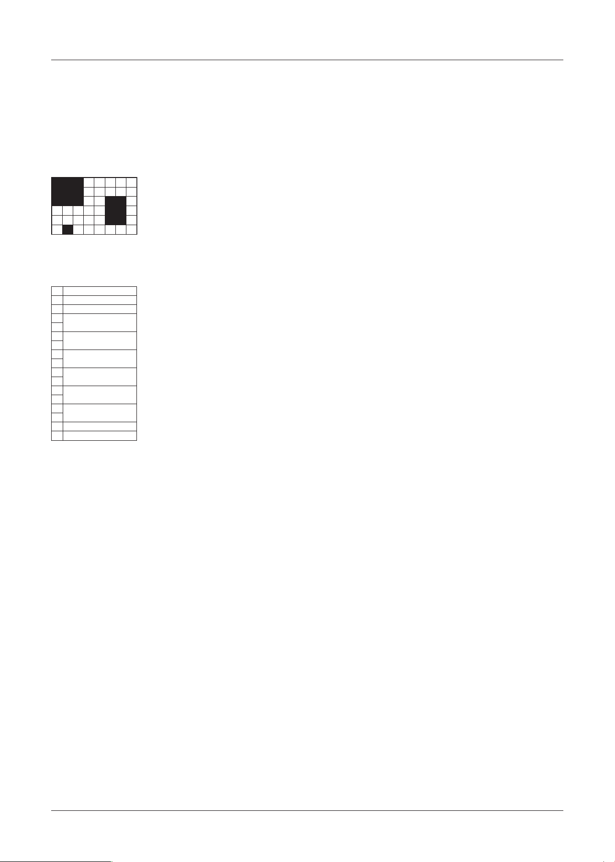
[7] Notes
Note 1 Area Settings
Divide the screen into 48 areas (6 vertical and 8 horizontal) and set an area to “1” to configure the mask and “0”
to not configure the mask. On a row, bits 1 to 4 from the left are on the upper level and bits 5 to 8 are on the lower
level. All six rows are connected in order from the top and transmitted according to protocol.
Example: Motion Mask Area Settings (Figure 1)
When setting Figure 1 (the area covered in black shows the position of the mask), transmit in the order described
below.
* The setting commands for the ATW Mask Area, Mask BLC Area are also transmitted using the procedure
described above.
* The Motion Detection Area (Query command Status type 8) also responds in the order described above.
(The area where motion is detected is set to “1”.)
− 20 −
Page 22

Communications Protocol
Model: VCC-MD800/700/600/500/400/300
Privacy Mask "5"
(0:OFF/1:ON)
Privacy Mask "1"
(0:OFF/1:ON)
Privacy Mask "7"
Privacy Mask "6"
(0:OFF/1:ON)
Privacy Mask "3"
Privacy Mask "2"
(0:OFF/1:ON)
Privacy Mask "8"
(0:OFF/1:ON)
(0:OFF/1:ON)
(0:OFF/1:ON)
(0:OFF/1:ON)
(0:OFF/1:ON)
* Except for 22x models
Reserve Reserve
Alarm Out Time
Alarm Duration
Baudrate 0:19200, 1:9600, 2:4800, 3:2400
0:RS485/1:COAX
Camera Address 0-127
21dB/
:
Alarm Out
ON)
:
OFF/1
:
0
(
Reserve Alarm in Polarity
ON)
:
OFF/1
:
0
(
0:NO 1:NC
ON)
:
NC)
:
NO/1
OFF/1
:
:
0
0
Alarm Out Polarity
(
(
Alarm Motion Mode
0:OFF,1:AND, 2:OR
Menu Return
(0:END/1:RETURN)
* Only 22x models
Menu(0:OFF/1:ON)
* Only 22x models
Focus
(0:Auto/1:Manual)
Focus
(0: Stop/1: Operating)
100
-
IRIS LEVEL 0
PAN/TILT Request in Menu
(0: No request/1: Request)
)
0:Long/1:OFF/3:Short
Shutter
(
D/N (0:COLOR/1:BW) Reserve D/N BURST
* Only 22x models
BLC mode
(0:OFF/1:Multi/2:Cent/
PAL_NT
(0:PAL/1:NTSC)
3:Mask)
detected/1: Detected)
0:0dB/1:3dB/
COLOR AGC
OFF Gain
(
Reserve
Reserve
Motion Detection
(0: Not detected/
1: Detected)
AGC
Shutter 0:Long/1:OFF/ 3:Short
2:6dB/3:9dB/ 4:12dB/5:15dB/ 6:18dB/7
8:24dB/9:27dB/ 10:30dB)
Reserve Terminate
Reserve
ON)
:
OFF/1
White Balance 0:ATW,1;AWC, 2:MWB, 3:Others
:
0
(
BW)
:
AUTO)
:
FIX/1
COLOR/1
:
:
0
0
D/N setting status
(
D/N status
(
Iris Level 0-15
PAL_NT
(0:PAL/1:NTSC)
ON)
:
OFF/1
:
0
(
Group 12 Group 8 Group 1 Reserve Reserve
Status1-1 Status1-2 Status1-3 Status1-4 Status1-5 Status1-6
(0:OFF/1:ON)
(0: Stop/1: Operating)
(0:OFF/1:ON)
Status Command 1
bit0 Digital Zoom
Note 2 Receiving Status
Refer to the various status commands for contents of the reply when querying the status.
⁃
bit1 zoom
bit3 Reserve D/N (0:FIX/1:AUTO) Privacy Mask "4"
bit2 Sens Up
bit4
White Balance mode
0:ATW/1;AWC/2:MWB/
(
3:Others)
bit5 Type (0:Normal/1:D/N) Reserve
bit6 Mirror (0:OFF 1:ON) Motion Detection (0: Not
bit7 0 Fixed 0 Fixed 0 Fixed 0 Fixed 0 Fixed 0 Fixed
ON)
ON)
bit1 Sense Up
:
OFF/1
:
0
(
bit2 BLC ON/OFF
ON)
:
OFF/1
:
0
(
* Only 22x models
bit3 Menu ON/OFF
bit4 Reserve Reserve Reserve Reserve Mirror
bit5 Reserve Reserve Reserve Reserve Reserve Reserve Reserve
bit6 Reserve Reserve Reserve Reserve Reserve Reserve Reserve Line Out
bit7 0 Fixed 0 Fixed 0 Fixed 0 Fixed 0 Fixed 0 Fixed 0 Fixed 0 Fixed 0 Fixed 0 Fixed
:
Status2-1 Status2-2 Status2-3 Status2-4 Status2-5 Status2-6 Status2-7 Status2-8 Status2-9 Status2-10
OFF/1
:
0
(
Status Command 2 (Except for MD300)
bit0 Digital Zoom
⁃
− 21 −
Status3-1 Status3-2 Status3-3 Status3-4 Status3-5 Status3-6
Camera ROM Version
Status Command 3 (Only MD400)
bit0
bit1 Group 13 Group 9 Group 2 Reserve Reserve
bit2 Group 14 Group 10 Group 3 Reserve Reserve
bit3 Group 15 Group 11 Group 4 Reserve Reserve
bit4 Reserve Reserve Group 5 Reserve Reserve
bit5 Reserve Reserve Group 6 Reserve Reserve
bit6 Reserve Reserve Group 7 Reserve Reserve
⁃
bit7 0 Fixed 0 Fixed 0 Fixed 0 Fixed 0 Fixed 0 Fixed
Page 23

Communications Protocol
Model: VCC-MD800/700/600/500/400/300
Day/Night Mode (0:COLOR/1:BW/2:AUTO)
D/N BURST (0:OFF/1:ON)
Privacy Mask "13"
(0:OFF/1:ON)
Privacy Mask "15"
(0:OFF/1:ON)
Privacy Mask "14"
(0:OFF/1:ON)
Privacy Mask "9"
(0:OFF/1:ON)
Privacy Mask "11"
(0:OFF/1:ON)
Privacy Mask "10"
(0:OFF/1:ON)
Privacy Mask "5"
(0:OFF/1:ON)
Privacy Mask "7"
(0:OFF/1:ON)
Privacy Mask "6"
(0:OFF/1:ON)
Privacy Mask "1"
(0:OFF/1:ON)
Privacy Mask "3"
(0:OFF/1:ON)
Privacy Mask "2"
(0:OFF/1:ON)
Reserve AGC DNR (0:OFF/1:ON)
Privacy Mask "12"
(0:OFF/1:ON)
Privacy Mask "8"
(0:OFF/1:ON)
Reserve Reserve Reserve Reserve Reserve
Privacy Mask "4"
Reserve Reserve Reserve Reserve Reserve
(0:OFF/1:ON)
Reserve Reserve Reserve Reserve Reserve
No. of Prolonged Exposure
Fields (1-32)
Lower AGC Gain
Value
(0: OFF/1: ON)
Still Settings
Motion Settings
(0: OFF/1: ON)
Motion Mask Settings
(0: OFF/1: ON)
Iris mode
0: AI, 1: MI (EI OFF), 2: MI (EI ON)
Status4-1 Status4-2 Status4-3 Status4-4 Status4-5 Status4-6 Status4-7 Status4-8
White Balance mode (0:ATW/1:AWC/ 2:MWB/3:3200/
(0:Auto/1:Manual)
Status Command 4 (Only MD800/700/600/500)
⁃
bit1
bit0 Focus
(0: OFF/1: ON)
Sync Settings
(0: INT, 1: LL)
BLC mode (0: OFF/1: Multi,/ 2: Cent/3: Mask)
4:5600/5:FLUO)
bit3 Aperture Settings
bit2
(0: OFF/1: ON)
Auto Mask Pos Settings
(0: OFF/1: ON)
(0:OFF/1:ON) Reserve
Reserve Reserve
WB MASK
bit4
bit5
bit6 Reserve Reserve Alarm Out Settings
Upper AGC Gain
Value
Lower Average
Luminance
Status6-1
Status5-1 Status5-2 Status5-3 Status5-4 Status5-5
Upper Average
Luminance
Status Command 5 (Only MD800/700/600/500)
bit7 0 Fixed 0 Fixed 0 Fixed 0 Fixed 0 Fixed 0 Fixed 0 Fixed 0 Fixed
bit0
bit1
bit2
bit3
bit4 Reserve Reserve Reserve Reserve
⁃
bit5 Reserve Reserve Reserve Reserve
Status Command 6 (Only MD800/700/600/500)
bit0 Motion Detection (0: Not detected, 1: Detected)
bit1 Alarm Output (0: Not output, 1: Output)
bit2 D/N Status (0: Color, 1: BW)
bit3 Reserve
bit6 Reserve Reserve Reserve Reserve Reserve
bit7 0 Fixed 0 Fixed 0 Fixed 0 Fixed 0 Fixed
⁃
bit4 Reserve
− 22 −
bit5 Reserve
bit6 Reserve
bit7 0 Fixed
Page 24

Communications Protocol
Model: VCC-MD800/700/600/500/400/300
Note 3 Exclusive processing
⁃
Setting to auto iris mode, when SENSE UP is set
When unable to set
Cannot be set when the motion sensor is set to
・
ON.
Cannot be set when auto pursuit is set to ON.
・
Auto switch setting
Sets AGC to ON.
・
Sets the shutter speed to normal settings.
・
⁃
Set to auto switch setting when set to manual
iris (EI ON)
Auto switch setting
Sets the shutter speed to normal settings.
・
⁃
When setting SENSE UP
(*Valid with auto iris mode)
When unable to set
Cannot be set when the motion sensor is set to
・
ON.
Cannot be set when AGC is set to OFF.
・
Cannot be set when auto pursuit is set to ON.
・
Auto switch setting
Sets the shutter speed to normal settings.
・
Changes V-RESO UP to OFF.
・
⁃
When setting shutter speed to high-speed
shutter mode (SHORT)
When unable to set
Cannot be set when set to auto iris and SENSE
・
UP.
Cannot be set when set to manual iris and EI ON.
・
⁃
When setting the shutter speed to long exposure
shutter mode (LONG)
When unable to set
Cannot be set when set to auto iris and SENSE
・
UP.
Cannot be set when set to manual iris and EI ON.
・
Cannot be set when the motion sensor is set to
・
ON.
Cannot be set when auto pursuit is set to ON.
・
Auto switch setting
Changes V-RESO UP to OFF.
・
⁃
When setting the motion setting to ON
When unable to set
Cannot be set when set to auto iris and SENSE
・
UP.
Cannot be set when the shutter speed is set to
・
long exposure shutter mode (LONG).
Auto switch setting
Changes auto pursuit to OFF.
・
⁃
When setting V-RESO UP to ON
When unable to set
Cannot be set when the shutter speed is set to
・
long exposure shutter mode (LONG).
Cannot be set when set to auto iris and SENSE
・
UP.
Cannot be set when set to AGC ON and DNR ON.
・
⁃
When setting DNR to ON (*Valid when AGC ON)
Auto switch setting
Changes V-RESO UP to OFF.
・
⁃
AWhen setting AGC to OFF
When unable to set
Cannot be set when D/N is set to AUTO.
・
Cannot be set when set to auto iris and SENSE
・
UP.
⁃
When setting D/N to AUTO
Auto switch setting
Changes AGC to ON.
・
⁃
When setting auto pursuit to ON
When unable to set
Cannot be set when set to auto iris and SENSE
・
UP.
Cannot be set when the shutter speed is set to
・
long exposure shutter mode (LONG).
Auto switch setting
Changes the motion sensor to OFF.
・
− 23 −
Page 25

Communications Protocol
2
ON
AUTOPURSUIT
△
※
OFF
MOTION
Model: VCC-MD800/700/600/500/400/300
○
D/N
AUTO
OFF
AGC
ON
DNR
ON
MOTION
shutter mode
Prolonged exposure
High speed
shutter mode
○ ○ ○
OFF
V-RESO UP
○
OFF
V-RESO UP
○
2
△
※
○
2
△
※
3
△
※
3
△
× × ○ ○ ○ ○ ○
※
○ ○ ○ ○ ○
Prolonged exposure
× ○ ○ ○ ×
shutter mode
High speed
shutter mode
○ ○
○
AGC
DNR invalid
○
ON
6
※
AUTO
○ ○ ○
OFF
PURSUIT
Settings to be
exclusiveprocessingtable.
(EI ON)
Manual Iris
ON
SENSE UP
ON
V-RESO UP
Auto Iris
changed.→
○ ○ ○ ○ ○ ○ ○ ○ ○ ○
Auto Iris
↓Current setting.
○ ○
OFF
V-RESO UP
○
ON
V-RESO UP
○
(SENSE UP invalid)
○
2
△
※
1
△
※
Auto Iris
ON
SENSE UP
Manual Iris
4
※
○
EI invalid
)
EI ON
(
Nomal mode Nomal mode
○ ○
High speed
shutter mode
Nomal mode Nomal mode
○ ×
Prolonged exposure
○ ○ × ○ ○ × ○ ○ ○
MOTION
shutter mode
ON
△
DNR
○ ○ ○ ○ ○
5
※
○
ON
AGC
○ ○ × ○ ○ ○ ○
OFF
D/N
○ ○ ○ ○ ○ ○ ○ ○ × ○
AUTO
○ ○ × ○ ○ ×
Setting change can be done at once.
ON
AUTO PURSUIT
○:
Setting can not be changed.
Enable to change the setting under certain condition.
Unable to set when MOTION ON or AUTO PURSUIT ON. Additionally, AGC will be ON and shutter speed is changed to normal mode.
Enable to set during Manual Iris setting.
Enable to set during Manual Iris (EI OFF) setting.
SENSE UP setting will be invalid. (It will be valid when changing the setting to AUTO Iris.)
Enable to set during AGC OFF.
:
×:
△:
2
Other than those above: "Changed setting" becomes valid but "Current setting" will be automatically changed to the settings mentioned in the table.
※ 1:
※
DNR is invalid.(It will be valid when changing the setting to AGC On.)
:
:
:
:
3
4
5
6
※
※
※
※
− 24 −
Page 26

Communications Protocol
Model: VCC-MD800/700/600/500/400/300
Note 4 Orientation / angle display
The display angle is changed using Pan/Tilt Degree
commands.
The Set North command sets the current position to N
and the pan degree to 0.
Pan angle versus orientation is as follows.
N 337.6-22.5
NE 22.6-67.5
E 67.6-112.5
SE 112.6-157.5
S 157.6-202.5
SW 202.6-247.5
W 247.6-292.5
NW 292.6-337.5
Note 5 How to set the Camera ID and Title
Detailed settings of Camera ID and Title settings are
as follows.
Set 8 (16) characters in ASCII code.
Transmit eight (16) characters at the time in order
starting with the first character. The following
characters may be used.
* The following value (HEX) is also answered as
response command to a query command.
* No Title settings are available for models MD400,
MD300.
* The numbers within the brackets refer to the VCC-
MD400 and MD300 models
Character
(Blank) 32 20 H 72 48
Code (HEX)
- 45 2D I 73 49
0 48 30 J 74 4A
1 49 31 K 75 4B
2 50 32 L 76 4C
3 51 33 M 77 4D
4 52 34 N 78 4E
5 53 35 O 79 4F
6 54 36 P 80 50
7 55 37 Q 81 51
8 56 38 R 82 52
9 57 39 S 83 53
: 58 3A T 84 54
A 65 41 U 85 55
B 66 42 V 86 56
C 67 43 W 87 57
D 68 44 X 88 58
E 69 45 Y 89 59
F 70 46 Z 90 5A
G 71 47
Character
Code (HEX)
Note 6 Rom Version display
No command other than the Version display ON/OFF
command will be received during Version display.
No OSD other than the Version OSD is displayed
during Version display.
The display will be erased 3 minutes after the ON
command is sent.
Note 7 ATW Smart exclusion processing
In models MD-300, 400 the Onepush Trigger by
Onepush Trigger (AWC set) command is not available
when setting the ATW Smart.
Before issuing an AWC set command set the ATW
Smart to OFF.
If setting the ATW Smart to ON again, do so once the
Onepush Trigger operation is complete (3 seconds) or
right before sending the ATW command.
Note 8 Pxel defect compensation
When pixel defect compensation function has been
executed by command, command transmission
cannot be done during the period described below
(not sending either ACK/NACK/ERR) :
MD600(P), MD500(P): 15 seconds
MD800(P), MD700(P): 20 seconds
Note 9 Pan/Tilt angle setting
Due to optimization on controlling Auto Focus and
Privacy Masks, send same coordinate data at least
twice when Pan/Tilt remain stationary.
Note10 Method of model distinguishing
5th digit in version
info
VCC-MD800(P) 5 1
VCC-MD700(P) 5 0
VCC-MD600(P) 4 1
VCC-MD500(P) 4 0
Version Query Command: 80 4A 0A CS FF
Version Response Command:
C0 4A 0A 0p 0q 0r 0s 0t 0u
0v 0w CS FF
x36:5
x30 :4
Status Command: 80 4A 01 CS FF
Status Response Command:
C0 4A 01 p q r s t u CS FF
↑
0 b6 b5 b4 b3 b2 b1 b0
↑
D/N :1
Color :0
bit5 of 3rd byte in status
command
↑
− 25 −
Page 27

Communications Protocol
*MD400(P), MD300(P) responds error(FC) with
commands above.
*Commands below can be used to detect MD400(P)
and MD300(P)
Status Command: 80 46 01 CS FF
Status Response Command:
C0 46 01 p q r s t u CS FF
↑
↑
0 b6 b5 b4 b3 b2 b1 b0
D/N (400(P) )
Color (300(P) )
:1
:0
Model: VCC-MD800/700/600/500/400/300
− 26 −
Page 28
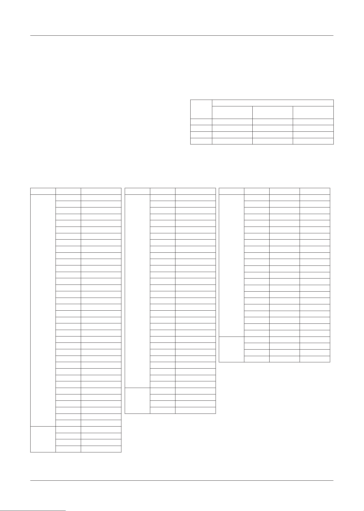
Function Descriptions
⁃
[1] Zoom Control
Zoom Position Control
The zoom can be operated using Tele/Wide or moving
the zoom to a specific position.
⁃
Direct
The Direct command can move the zoom lens to the specified zoom lens position.
The relation between the zoom lens position and magnification is as follows.
Digital Zoom Tele Limiter command needs to be sent before the Direct command when moving to digital zoom eld.
Optical
Area
Electronic
Area
Magnification
10x 1970
11x 2014
12x 2054
13x 2091
14x 2124
15x 2156
16x 2186
17x 2214
18x 2241
19x 2267
20x 2291
21x 2314
22x 2335
23x 2355
24x 2373
25x 2389
26x 2404
27x 2418
28x 2429
29x 2439
30x 2449
31x 2456
32x 2464
33x 2470
34x 2476
35x 2481
36x 2484
72x 2612
144x 2676
288x 2708
576x 2724
MD700(P), 800(P)
1x 0
2x 864
3x 1232
4x 1456
5x 1600
6x 1709
7x 1792
8x 1862
9x 1920
Optical
Area
Electronic
Area
Magnification
10x 1866
11x 1909
12x 1948
13x 1983
14x 2015
15x 2044
16x 2071
17x 2096
18x 2119
19x 2140
20x 2158
21x 2176
22x 2191
23x 2205
24x 2217
25x 2228
26x 2238
27x 2246
28x 2254
29x 2260
30x 2263
60x 2391
120x 2455
240x 2487
480x 2503
MD500(P), 600(P)
1x 0
2x 813
3x 1163
4x 1368
5x 1508
6x 1612
7x 1693
8x 1760
9x 1817
Tele/Wide
Transmit the Tele or Wide command to execute the
Tele/Wide operation at the speed configured by the
Tele/Wide Speed command. The Stop command
stops the operation. (The operation does not stop
without transmitting the Stop command.)
The speed targets are as follows.
Required Time (s) from Wide End → Tele End
Settings
1 11.7 9.9 5.7
2 8.3 6.6 4.9
3 6.8 5.1 4.3
4 5.8 4.2 4.0
MD700
x36
MD800
Optical
Area
Electronic
Area
MD500
x30
MD600
Magnification
1x 0 0
2x 854 686
3x 1218 972
4x 1429 1143
5x 1573 1271
6x 1681 1354
7x 1766 1420
8x 1837 1482
9x 1898 1528
10x 1951 1572
11x 1998 1612
12x 2041 1642
13x 2077 1686
14x 2110 1700
15x 2139 1729
16x 2163 1743
17x 2184 1772
18x 2201 1786
19x 2216 1795
20x 2229 1800
21x 2239 1815
22x 2248 1829
44x 2376 1957
88x 2440 2021
176x 2472 2053
352x 2488 2069
MD300(P) MD400(P)
MD300
x22
MD400
− 27 −
Page 29

Function Descriptions
Optical Zoom Limit Settings
The optical zoom magnification can be limited using
the Optical Zoom Tele Limiter command. The digital
zoom cannot be used if the limit is set to the Tele side.
Digital Zoom
A maximum of 16x digital zoom can be set with the
Digital Zoom Tele Limiter command. Together with
the optical zoom, a maximum of 480x is possible,
however, the resolution decreases.
Although the vertical resolution can be increased by
enabling the V-Reso.UP function using the V-Reso.
UP ON command, residual images and blurring may
become more apparent with moving subjects.
[2] Focus Control
Manual Focus
The manual focus can be operated using Far/Near or
directly moving the focus to a specific position.
⁃
Far /Near
Transmit the Far or Near command to execute the
Far/Near operation at the speed configured by the
Far/Near Speed command. The Stop command
stops the operation. (The operation does not stop
without transmitting the Stop command.)
The speed targets are as follows.
Required Time (s) from Near End → Far End
Settings
x36
MD800
1 19.7 16.0 19.0
2 10.3 8.3 9.7
3 4.4 3.6 6.6
4 2.4 2.1 5.2
at the Near Limit 1m and Tele End
MD700
MD500
x30
MD600
MD300
x22
MD400
One-Push Auto Focus
The auto focus can be moved only once using the
One Push Trigger command. The mode prior to
starting the auto focus is retained after focusing.
Focus Lens Offset
When covering a camera, such as the dome camera
with a cover or similar, the refraction of the light due to
the cover changes the OPL. This may result in close
subjects being out of focus when using a powerful
zoom.
In that case, it is necessary to move the range of
motion of the focus lens depending on the change in
OPL.
Validate the Offset using the Cover Offset ON
command and transmit a Cover Offset Level
command so that subjects that are at approximately
1m TELE edge (When the Near Limit is 1m) are in
focus.
In the same way that 0 sets the level to OFF, the
larger the number, the greater the offset.
[3] White Balance Control
⁃
ATW
Auto Trace White Balance.
SMART ATW
・
This mode controls retracing of ATW according
to the size of single-colour object in the screen,
addition to normal ATW mode control.
In case the single-colour object covers most of
the area in the screen, WB control function shall
be stopped.
Also, the retracing speed is slower than that of
normal ATW mode.
*This mode is valid when WB mode is set to ATW.
⁃
Direct
The Direct command can move the zoom lens to the
specified focus lens position.
⁃
Auto Focus
The Auto Focus ON command sets the mode to auto
focus and automatically focuses on the subject if
the subject moves. This mode is cancelled when the
Manual Focus ON, Near, or Far command is used.
Although the minimum focus distance is set to 1m by
default, this can be changed by using the Near Limiter
command. In addition, the sensitivity of the AF to the
change in subject can be changed using the Auto
Focus Sensitivity command and the focusing area can
be changed using the Focus Area command.
− 28 −
⁃
AWC
The Push-Lock Auto White Balance starts retracting
using the One Push Trigger command and locks the
white balance after approximately 2 seconds.
In addition, after executing the One Push Trigger
command, the mode returns to the previous mode
by executing the AWC Reset command.
⁃
3200K
Color temperature 3200K fixed mode.
⁃
5600K
Color temperature 5600K fixed mode.
⁃
FLUO
Color temperature 4200K fixed mode.
⁃
MWB
Manual White Balance. The R and B gains can each
be configured to a range of 0 to 255.
Page 30

Function Descriptions
[4] IRIS Control
⁃
Auto Iris
The lens aperture is automatically controlled to
correct the brightness of the average luminance
value of the image.
⁃
Manual Iris
This fixes the lens aperture. The aperture position
can be set to a range of 17 levels (1: close - 7:
open) using the Manual IRIS Stop command.
EI ON
・
The light intensity can be controlled to a fixed level
using an electronic shutter control.
Note: Executing the EI ON command sets the
shutter speed mode to OFF.
EI OFF
・
This fixes the electronic shutter. Refer to the
Shutter Speed Control on the next page regarding
fixed values.
⁃
SENSUP
If the illumination of the subject decreases, the
Prolonged Exposure Control is automatically
executed along with the AGC Control.
The maximum Field Accumulation Time can be
configured to a range of 1x to 32x.
This cannot be configured during the following
conditions.
When the MOTION settings are valid.
・
When AGC is OFF.
・
In addition, the shutter speed mode is set to OFF.
[6] AGC Control
⁃
AGC ON
The gain is automatically controlled and light is fixed
to a certain intensity.
The MAX gain of each mode of LOW/NORMAL/
MIDDLE/HIGH is roughly equivalent to the following
gains.
⁃
Iris Level
The target brightness can be configured to a range
of 0 to 100.
[5] Shutter Speed Control
⁃
Prolonged Exposure Mode
The exposure time is a longer mode than 1 field.
The field accumulation time can be configured from
1x to 32x.
However, this cannot be configured during the
following conditions.
When SENSE UP is enabled.
・
When MOTION settings are enabled.
・
When EI is ON.
・
⁃
Normal Mode
This is fixed to 1/60 (1/50).
⁃
High-Speed Shutter Mode
This can be configured from 1/60 to 1/10000.
Note 1) If flickering is noticeable in regions with
a power supply frequency of 50Hz when
using NTSC, switch to the High-Speed
Shutter Mode (1/100).
AGC Gain (dB)
LOW NORMAL MIDDLE HIGH
AUTO — 9dB 12dB 15dB
COLOR 1.5dB 6dB 10.5dB 15dB
B/W 6dB 9dB 12dB 15dB
⁃
AGC OFF
This is the fixed gain mode. The gain value can be
manually configured to 11 steps.*
The gain value of each step is roughly equivalent to
the following gains.
Gain Direct
Configuration Value
0 0dB
1 3dB
2 6dB
3 9dB
4 12dB
5 15dB
6 18dB
7 21dB
8 24dB
9 27dB
10 30dB
Note: When the Day/Night mode is set to AUTO, the AGC OFF
cannot be set.
Gain
Note 2) When switching to the Prolonged Exposure
or High-Speed Shutter Mode, transmit the
“Shutter Speed Set Mode” command after
the “Shutter Long Direct” or “Shutter Short
Direct” command.
− 29 −
Page 31
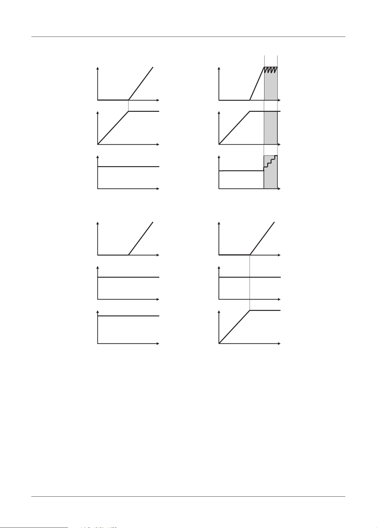
Function Descriptions
AGC Gain AGC Gain
AGC Gain AGC Gain
Lens Aperture (Optional)
IRIS
OFF
OFF
OFF
Electronic Shutter (Optional)
Electronic Shutter
Lens
Aperture
Lens
Aperture
Electronic Shutter
(Optional)
Electronic Shutter
(Fixed at 1/60 or 50)
High Sensitive Photograph
Auto Iris (SENSE UP OFF) Diagram 1 Auto Iris (SENSE UP ON) Diagram 2
Manual Iris (EI OFF) Diagram 3 Manual Iris (EI ON) Diagram 4
Lens
Aperture
(Optional)
Subject is dark
Subject is dark
Subject is dark
Subject is dark
Prolonged Exposure
Max
0dB
open
close
Slow
Fast
Max
0dB
open
close
Slow
Fast
Max
0dB
open
close
Slow
Fast
Max
0dB
open
close
Slow
Fast
[7] Backlight Compensation
⁃
Multi-Area Light Measuring
This automatically detects the subject area, the
backlight conditions, and automatically corrects the
backlight.
The following settings configure sensitivity and the
effectiveness of corrections when there is backlight.
BLC Weight
・
The sensitivity to backlight can be configured to a
range of 0 to 15.
Larger values increase the sensitivity to backlight.
BLC Bright
・
The target brightness value of the subject area
when there is backlight can be configured to a
range of 0 to 15.
Larger values increase the effectiveness of the
correction.
− 30 −
⁃
Center-weighted metering
The 48 total areas are divided into 5 and brightness
levels are corrected by weighting and calculating
each area.
The weight of each area can be configured to a
range of 0 to 7. (CENTER is fixed at 7.)
The CENTER position and size can be changed
according to the position of the subject.
⁃
BLC Mask
By specifying masked areas within the 48 total
areas, brightness information of the masked areas
is ignored and brightness levels are corrected.
Note: When the Day/Night switch control is set to
AUTO mode, the backlight cannot be corrected
with multi-area light measuring when the
camera is set to B/W.
Page 32

Function Descriptions
[8] Aperture
Emphasizes contours and increases the vividness of
the entire image.
[9] Motion Detection
The screen is divided into 48 areas (8 x 6) and
movement is detected from changes in brightness of
representative points within each area.
The detection status can be confirmed by enquiring
using the Status command.
In addition, the detection sensitivity can be adjusted
by configuring the following items.
⁃
Sensitivity (MOVE)
Sensitivity when determining movement can be
configured to a range of 1 to 10. 1 is the most
sensitive to movement.
⁃
Brightness Level (Y-LEVEL)
Settings for minimum brightness level when
determining movement (Valid for brightness above
the configured level)
The configuration range is 1 to 10. 1 is the most
sensitive to the minimum brightness level.
[10] Day/Night Switch Control
⁃
AUTO
Automatically switches the camera from color
images to black and white images depending on
the brightness of the day and night. The illumination
level at which the camera changes from color
images to black and white images can be set to
3 levels (MID, HIGH, LOW) or to manual (ADJ)
setting.
⁃
COLOR
Fixes the camera to color images.
⁃
B/W
Fixes the camera to black and white images.
⁃
Brightness Difference (Y-Differ)
Settings for differences in brightness of the 2
images when determining movement (Invalid when
exceeding configured brightness differences)
The configuration range is 1 to 10. 1 is the most
sensitive to the difference in maximum brightness.
⁃
Time Interval (Duration)
Time interval settings when determining movement
The configuration range is 1 to 60. 1 is the most
sensitive to minimum time intervals.
⁃
Time intervals are divided into 5 fields.
Movement Assessment Confirmation Mode (TEST)
− 31 −
Page 33

0x26 (0x2A) 0x6C (0x6E) 0x9E (0x9F) 0xE4 (0xE3)
0x07 (0x0A)
0x35 (0x41)
0x54 (0x64)
0x82 (0x9B)
TILT = −90˚
TILT = 90˚
PAN = 90˚
PAN = 270˚
PAN = 180˚
TILT = +/−180˚
PAN = 0˚ / 360˚
TILT = 0˚
Function Descriptions
[11] Privacy Mask Settings
Display Area: NTSC (PAL)
*
Area initially displayed using the Area Mask ON
command.
Notes:
Minimum unit for the mask width is 4 pixels
・
horizontally and minimum unit for the mask height is
2 lines vertically.
Up to 4 mask can be displayed within one view
・
angle.
To correctly hide the masked subject when loading
・
the dome camera, update the PAN/TILT angle
interval to within 75 ms.
Details of the Mask Angle and Position
Setting the Mask Angle (Area Mask Degree Set)
The angle is displayed as 12 bits and divided into 4-bit
units when increased by a magnification of 10.
Example) Setting the mask angle according to the
following parameters during NTSC
Mask Number 1
Pan Angle 135°
Tilt Angle 45°
Pan Angle:
1350 → 0x0546 → q = 5, r = 4, s = 6
Tilt angle sign bit:
If the tilt angle is positive → x = 0
Tilt Angle:
450 → 0x01C2 → t = 1, u = C, v = 2
Transmitted according to the following.
A0 10 11 01 05 04 06 01 0C 02 CS FF
According to the setting above, if the tilt angle only is
set to -45 degrees the following codes are transmitted.
A0 10 11 01 05 04 06 11 0C 02 CS FF
Area Mask Degree Set
Command: A0 10 11 0p 0q 0r 0s xt 0u 0v CS FF
Parameter:
p Mask Number (No. 1-15)
qrs Pan Angle (0°-360°)
x Tilt angle sign bit
tuv Tilt Angle (0°-180°)
Usage: Sets the angle of the specified mask numbers.
Note: Set using a pan angle range of 0°-360° and
a tilt angle range of –180°-180°. (Refer to the
diagram on the right)
In addition, when setting a negative tilt angle
set the tilt angle code bit x to 1.
Area Mask Position Set
Command: A0 10 09 0p 0q 0r 0s 0t 0u 0v 0w 0x CS
FF
Parameter:
p Mask Number (No. 1-15)
qr x-Coordinate Start Position
st y-Coordinate Start Position
uv x-Coordinate End Position
wx y-Coordinate End Position
Usage: Sets the position of the specified mask numbers.
Note: Set the mask size to sufficiently cover the mask
object. In addition, ensure that the settings are
set on the WIDE end.
*Query Command Mask Position responds in the
same parameter as described above.
− 32 −
Page 34

x-Coordinate
Start Position
x-Coordinate
End Position
y-Coordinate
Start Position
y-Coordinate
End Position
x
y
Mask Height
Mask Width
x
Function Descriptions
Setting the Mask Position (Area Mask Position Set)
If the coordinates increase by 1, the position moves
by 4 horizontal pixels and 2 vertical lines.
The upper left and lower right horizontal and vertical
coordinates (1 byte each) are each divided into upper
and lower 4 bits.
Example) Setting the mask position according to the
following parameters during NTSC
Mask Number 1
x-Coordinate Start Position 0x48
y-Coordinate Start Position 0x1C
x-Coordinate End Position 0x82
y-Coordinate End Position 0x40
Pan Angle 135°
Tilt Angle 45°
Settings Increasing Privacy Mask Accuracy
(MD800-MD500)
Area Mask Position Center Set
Command: A0 10 0A 0p 0q 0r 0s 0t CS FF
Parameter:
p Mask Number (No. 1-15)
qr Mask Width
st Mask Height
Usage: Sets the mask position mainly according to the
optical.
Note: Set the mask size to sufficiently cover the mask
object. In addition, ensure that the settings are
set on the WIDE end.
The minimum unit of the mask width is 4
horizontal pixels and the minimum unit of the
mask height is 2 vertical lines.
Setting Procedures
1. Mask Position (x, y coordinates) Settings
(Area Mask Position Set)
A0 10 09 01 04 08 01 0C 08 02 04 00 CS FF
2. Mask Angle Settings (only during PTZ)
(Area Mask Degree Set)
A0 10 11 01 05 04 06 01 0C 02 CS FF
3. Setting Mask ON (Area Mask ON)
A0 10 01 01 CS FF
Example) Setting the mask position according to the
following parameters during NTSC
Mask Number 1
Mask Width 0x50
Mask Height 0x3C
Pan Angle 135°
Tilt Angle 45°
Setting Procedures
1. Mask Position (width and height) Settings
(Area Mask Position Center Set)
A0 10 0A 01 05 00 03 0C CS FF
2. Mask Angle Settings (only during PTZ)
(Area Mask Degree Set)
A0 10 11 01 05 04 06 01 0C 02 CS FF
3. Setting Mask ON (Area Mask ON)
A0 10 01 01 CS FF
− 33 −
Page 35

Function Descriptions
[12] Stabilizer
(Only VCC-MD700/800 series)
When this function is set to ON, the digital zoom
magnifies the screen. When vibrations are detected,
the vibrations are stabilized by changing the position
of the screen captured by the zoom.
Stabilizer level and digital zoom magnification
When changing the stabilizer level, the magnification
of the applied digital zoom is changed. Therefore,
increasing the stabilizer level allows the camera to
adjust to stronger vibrations. However, the screen
resolution decreases.
The relation between the level of stabilization and the
digital zoom magnification is as follows.
Stabilizer level Applicable digital zoom magnification
Low Approximately x1.05
Middle Approximately x1.1
High Approximately x1.2
Frequency that can be stabilized
This function corrects vibrations between 5Hz – 15Hz.
However, depending on the strength of the vibration
or the stabilizer level, some vibrations within this
frequency range may not be stabilized.
To clarify the image when using the stabilizer
To clarify the image when using the stabilizer, set the
shutter speed to approximately 1/250.
If the shutter speed is slow, the images captured
before the digital zoom is applied will be blurred and
the effect of the stabilizer decreased.
− 34 −
Page 36

Function Descriptions
Up: 100%
Center
Right: 100%
Left: 100%
Down: 100 %
[13] Auto Pursuit Function
Detects movement on the screen and calculates the
level of movement.
Subject pursued: Walking person
Area:1x Zoom, object = a person at 8m distance
Speed: 4km/hour - 6km/hour
Motion detection: Uses the motion detection function
Detection area: 16 x 12, total of 192 blocks
Detection conditions: Continuous movement
detection area
Auto Pursuit ON/OFF Setting
Sets auto pursuit to ON/OFF.
Command: A0 34 000pCSFF
p: OFF:0、ON:1
Auto Pursuit Sensitivity Setting
Sets the sensitivity to brightness variation when
detecting motion.
Higher sensitivity increases motion detection through
less brightness variation.
Moving Distance Query Command
Returns the distance to the distance derived from the
center of gravity of the moving subject. This value
represents the distance. Calculate the PAN/TILT
distance adequately using this value.
Command: 804A07CSFF
Response: C04A070p0q0r0s0t0u
CSFF
Parameter description:
p: Movement direction (Lateral) (1: Right, 2: Left)
q: Movement direction (Vertical) (1: Up、 2: Down)
rs: Lateral movement distance (%)
tu: Vertical movement distance (%)
Command: A034010pCSFF
p: 1-F (High sensitivity – Low sensitivity)
Note:
When auto pursuit is set to ON, the ALARM
・
MOTION setting is forcibly set to OFF.
Pursues the largest moving subject when several
・
moving subjects are detected within one angle.
For Day/Night models, when the IR cut filter is in
・
operation the moving subject is not pursued.
When the zoom lens, focus lens are in operation, the
・
moving subject is not pursued.
When the PAN/TILT information is changed, the
・
。
moving subject is not pursued
When LONG SHUTTER, SENSE UP is set, auto
・
pursuit cannot be set to ON.
Example: when p = 0x01, q = 0x01, rs = 0x64, tu =
0x64, the PAN/TILT moves right: 100%,
up: 100%. Control the PAN/TILT moving
distance so that the subject in the top right
corner is in the Center.
The minimum transmission interval of movement
distance query command is 150msec.
− 35 −
Page 37

Application Software
[1]
Camera Control Command Transmission
1-1 Control using the Command Button
The camera unit can be controlled by clicking the
various command buttons.
The command data transmitted and received by the
PC can be confirmed using the “SENDING DATA” and
“RECEIVING DATA” windows.
Command Button Operation
Zoom (TELE/WIDE) Controls the ZOOM function.
Press down the button to start the ZOOM function.
Release the button to stop the ZOOM function.
Focus (FAR/NEAR) Controls the FOCUS function.
Press down the button to start the FOCUS function.
Release the button to stop the FOCUS function.
Focus (Auto/Manual/1PushAF) Selects the FOCUS function mode.
Shutter Speed (Shutter Speed) (−/OFF/+) Selects the shutter speed function mode.
Click the OFF button to return to initial settings.
Iris (Auto/Manual EI OFF/Manual EI ON) Selects the iris function mode.
Iris (Level−/Level+) Selects the iris level.
White Balance (Auto/Manual/1 push/3200K/5600K/FLUO) Selects the white balance mode.
White Balance (R−/R+/B−/B+) Use the color R and B levels to adjust the white balance according to
lightening conditions.
BLC (OFF/MULT/CENT/MASK) Selects the BLC mode.
AGC (ON/OFF) Selects the AGC mode. (AGC OFF is invalid when Day/Night is set to
AUTO.)
Version Displays the version of the connected camera.
1-2 Input Command Data Controls
(Refer to the command list)
The camera unit can be controlled by entering the
command data into the PC.
Enter a specific protocol in the box within the
“SENDING DATA” window (starting from box No.0).
The camera is operated by clicking the “Manual Send”
button. Similar to Item 1-1 (control using command
button), the data received from the camera can be
confirmed in the “RECEIVING DATA” window.
In addition, display can be switched between a
decimal/hexadecimal number display using “DEC”,
“HEX”.
[2] Communications Error
An error message displays when a communications
error occurs and communication between the camera
and PC stops for several seconds.
Communication can be stopped manually by clicking
the “Manual Stop” button.
[3] RS-232C Port
Select the port to connect the RS-232C cable from
COM1 to COM4 using the “Port” button
[4] BAUDRATE
Select the communication speed using the
“BAUDRATE” button.
[5] ID SET, ID Keyboard
The camera ID can be set in the “ID SET”, “ID
Keyboard” tabs.
(Does not apply to MD-300, 400 models)
− 36 −
Page 38

Spectral Sensitivity Characteristics
Relative Response
Wave Length [nm]
1.0
0.8
0.6
0.4
0.2
0
Ye
G
Cy
Mg
400 450 500 550 600 650 700
1.0
0.8
0.6
0.4
0.2
0
Ye
G
Cy
Mg
400 450 500 550 600 650 700
Relative Response
Wave Length [nm]
Relative Response
Wave Length [nm]
1.0
0.9
0.8
0.7
0.6
0.5
0.4
0.3
0.2
0.1
0
400 500 600 700 800 900 1000
MD800(P) (Color Mode)
MD700(P)
MD600(P) (Color Mode)
MD500(P)
MD400(P) (Color Mode)
MD800(P) (Night Mode)
MD600(P) (Night Mode)
MD400(P) (Night Mode)
MD300(P)
− 37 −
Page 39

Specifications
• NTSC system
Model VCC-MD800 VCC-MD700 VCC-MD600 VCC-MD500 VCC-MD400 VCC-MD300
Image size 1/4" interline transfer CCD
Effective picture elements 768(H) x 494(V)
Lens
View angle
Digital zoom 16x
Resolution 520 TV lines
Minimum illumination
S/N ratio more than 50dB (AGC OFF)
Synchronizing system Internal/External (Vsync)
Auto focus Auto/One-push AF/Manual
Day/Night function Auto/Color/B/W – Auto/Color/B/W – Auto/Color/B/W –
Image stabilizer On/Off – – –
White balance ATW/Manual/Push-Look/In-door/Out-door/Fluorescent ATW/Manual/Push-Look
AGC Low/Normal/Middle/High/Off On (adjust gain)/Off
Backlight compensation Multi/Center/Off
Electronic shutter speed
Electronic sensitivity Auto/Off, max 32 times
Privacy masking On/Off, max of 15 masked locations (Wide view screen; 1 screen max 4 masks)
Mirror image effect H/V/HV/Off
Image freeze On/Off
Motion detector On/Off, with motion zoom function
Video output 1.0 Vp-p/75 ohms (composite), Y/C output (option)
Communication RS-232C (TTL level)
Operating temperature –10 to 50˚C
Power source
Power consumption
Dimensions 50(W) x 60(H) x 86.2(D) mm 50(W) x 60(H) x 87.5(D) mm 50(W) x 60(H) x 89.5(D) mm
Weight Approx. 240g Approx. 230g
Horizontal 57.8° to 1.7° 56.4° to 2.0° 47.9° to 2.3° 47.3° to 2.2°
Vertical 43.7° to 1.3° 43.3° to 1.3° 36.9° to 1.7° 36.3° to 1.4°
Diagonal 71.1° to 2.0° 68.1° to 2.3° 58.1° to 2.8° 57.4° to 2.5°
Day/night Color Day/night Color Day/night Color
(F1.6, color,
gain: max.)
(F1.6, B/W,
gain: max.)
(F1.6, B/W, 32x)
DC9V
DC12V: 3.2W (3.5W, motors active)
36x ZOOM 30x ZOOM 22x ZOOM
36x optical zoom
f=3.4–122.4 mm, F1.6–4.5
1.0lx
(F1.6, gain: max.)
0.05lx
0.0015lx
DC6V: 2.4W
2.8W(3.1W ,motors active
:
30x optical zoom
f=3.5–105 mm, F1.4–3.7
1.0lx
–
–
(Fast) 1/60, 1/100, 1/250, 1/500, 1/1000, 1/2000, 1/4000, 1/10000sec
6–12V DC
(Recommendation: DC9V)
)
0.8lx
(F1.4, color,
gain: max.)
0.04lx
(F1.4, B/W,
gain: max.)
0.0013lx
(F1.4, B/W, 32x)
(Slow) 1x, 2x, 4x, 8x, 16x, 32x
DC6V: 2.1W
DC9V:2.5W(3.1W ,motors active
DC12V: 2.8W (3.4W, motors active)
0.8lx
(F1.4, gain: max.)
–
–
22x optical zoom
f=3.6–79.2 mm,
(F1.6, color,
gain: max.)
(F1.6, B/W,
gain: max.)
(F1.6, B/W, 32x)
)
F1.6–3.8
1.2lx
0.06lx
0.002lx
22x optical zoom
f=4–88 mm,
F1.6–3.8
2.0lx
(F1.6, gain: max.)
9–12V DC
450mA/12V DC
–
–
− 38 −
Page 40

Specifications
• PAL system
Model VCC-MD800P VCC-MD700P VCC-MD600P VCC-MD500P VCC-MD400P VCC-MD300P
Image size 1/4" interline transfer CCD
Effective picture elements 752(H) x 582(V)
Lens
View angle
Digital zoom 16x
Resolution 520 TV lines
Minimum illumination
S/N ratio more than 50dB (AGC OFF)
Synchronizing system Internal/External (Vsync)
Auto focus Auto/One-push AF/Manual
Day/Night function Auto/Color/B/W – Auto/Color/B/W – Auto/Color/B/W –
Image stabilizer On/Off – – –
White balance ATW/Manual/Push-Look/In-door/Out-door/Fluorescent ATW/Manual/Push-Look
AGC Low/Normal/Middle/High/Off On (adjust gain)/Off
Backlight compensation Multi/Center/Off
Electronic shutter speed
Electronic sensitivity Auto/Off, max 32 times
Privacy masking On/Off, max of 15 masked locations (Wide view screen; 1 screen max 4 masks)
Mirror image effect H/V/HV/Off
Image freeze On/Off
Motion detector On/Off, with motion zoom function
Video output 1.0 Vp-p/75 ohms (composite), Y/C output (option)
Communication RS-232C (TTL level)
Operating temperature –10 to 50˚C
Power source
Power consumption
Dimensions 50(W) x 60(H) x 86.2(D) mm 50(W) x 60(H) x 87.5(D) mm 50(W) x 60(H) x 89.5(D) mm
Weight Approx. 240g Approx. 230g
Horizontal 57.8° to 1.7° 56.4° to 2.0° 47.9° to 2.3° 47.3° to 2.2°
Vertical 43.7° to 1.3° 43.3° to 1.3° 36.9° to 1.7° 36.3° to 1.4°
Diagonal 71.1° to 2.0° 68.1° to 2.3° 58.1° to 2.8° 57.4° to 2.5°
Day/night Color Day/night Color Day/night Color
(F1.6, color,
gain: max.)
(F1.6, B/W,
gain: max.)
(F1.6, B/W, 32x)
DC9V:2.8W(3.1W ,motors active
DC12V: 3.2W (3.5W, motors active)
36x ZOOM 30x ZOOM 22x ZOOM
36x optical zoom
f=3.4–122.4 mm, F1.6–4.5
1.0lx
(F1.6, gain: max.)
0.05lx
0.0015lx
DC6V: 2.4W
30x optical zoom
f=3.5–105 mm, F1.4–3.7
1.0lx
–
–
(Fast) 1/50, 1/120, 1/250, 1/500, 1/1000, 1/2000, 1/4000, 1/10000sec
6–12V DC
(Recommendation: DC9V)
)
0.8lx
(F1.4, color,
gain: max.)
0.04lx
(F1.4, B/W,
gain: max.)
0.0013lx
(F1.4, B/W, 32x)
(Slow) 1x, 2x, 4x, 8x, 16x, 32x
DC6V: 2.1W
DC9V:2.5W(3.1W ,motors active
DC12V: 2.8W (3.4W, motors active)
0.8lx
(F1.4, gain: max.)
–
–
22x optical zoom
f=3.6–79.2 mm,
(F1.6, color,
gain: max.)
(F1.6, B/W,
gain: max.)
(F1.6, B/W, 32x)
)
F1.6–3.8
1.2lx
0.06lx
0.002lx
22x optical zoom
f=4–88 mm,
F1.6–3.8
2.0lx
(F1.6, gain: max.)
9–12V DC
450mA/12V DC
–
–
1AC6P1P3146-L5BT2/XE, US2 (0307KR)
− 39 −
Page 41

Change history
2006.12.20: the issue of ver 1.00
2007.02.15: the issue of ver 1.01
Changes the DEFAULT communication speed (BAUDRATE) of the MD800 – 500 to 9600 bps. •
Newly added commands. •
Cover Offset OFF/ON
Cover Offset Level
Auto Focus Mode during pan/tilt
ATW Mask Display
Center BLC Area Display
BLC Mask Display
Motion Size Display
Motion Mask Display
D/N Filter Slide Time
Status type 7
Status type 8
Newly added stabilizer function command and function description (only MD700/800 can be used).•
Newly added auto pursuit function command and function description. •
Newly added exclusive processing note.•
Newly added focus lens offset function description. •
Newly added icon of application software and description postscript.•
Revised privacy mask setting note. •
Revised power source, power consumption specifications.•
2007.05.10: the issue of ver 1.02
Newly added commands.•
OSD setting command (MD500 – 800 only)
Camera ID setting command
Area Mask Position Full Screen Set (MD 500-800 only)
Mask Area Center Position (MD 500-800 only)
The privacy mask maximum setting value has been increased from 8 to 15. (MD 500-800 only)•
The tilt degree range of the Privacy Masking, Pan/Tilt Degree command has been expanded to: –180 to 180 •
degrees. The related commands and instructions have been revised. (MD500-800 only)
Newly added angle area to the specifications of each model.•
2007.06.19: the issue of ver. 1.03
Newly added commands.•
Zoom Direct with Focus (MD500 – 800 only)
Change in required time from Wide end •
2007.11.01: the issue of ver.1.04
Add new commands below: •
Pixel defect compensation command.
Auto pixel defect compensation command at start-up.
Revise Zoom Direct with Focus command. •
Add exclusive processing table.•
Add method of model distinguishing.•
Add Smart ATW description.•
Add info regarding time-period of accepting the commands after start-up. •
Add notices below: •
Pixel defect compensation function
Tele end
Auto pursuit function
− 40 −
Page 42

Change history
Shifting to digital zoom area
Pan/Tilt Degree commands
Center BLC Area Direct commands
Privacy Mask related commands
− 41 −
 Loading...