

Page 1
INSTRUCTION MANUAL
Color CCD Camera
About this manual
Before installing and using this unit, please read this manual carefully.
Be sure to keep it handy for later reference.
VCC-MC600P
VCC-MC500P
Page 2

Contents
Main Features . . . . . . . . . . . . . . . . . . . . . . . . . . . . . . .2
Precautions. . . . . . . . . . . . . . . . . . . . . . . . . . . . . . . . .3
Before Using the Menu . . . . . . . . . . . . . . . . . . . . . . .4
Basic Operations for Performing Settings
in the Menu . . . . . . . . . . . . . . . . . . . . . . . . . . . . . . . . .5
About Setting Menus . . . . . . . . . . . . . . . . . . . . . . . . .6
■ Setting menu mode . . . . . . . . . . . . . . . . . . . . . . . . . 6
■ Setting menu composition. . . . . . . . . . . . . . . . . . . . 7
Camera Settings (CAMERA) . . . . . . . . . . . . . . . . . . .8
A
Adjusting synchronization signal (SYNC) . . . . . . 10
B Setting lens aperture (IRIS) . . . . . . . . . . . . . . . . . . 11
■ Auto iris (AUTO). . . . . . . . . . . . . . . . . . . . . . . . . . . . . . 11
■ Manual iris (MANU) . . . . . . . . . . . . . . . . . . . . . . . . . . . 11
C Setting the white balance (WHITE BALANCE) . . . 12
■ Auto trace white balance (ATW). . . . . . . . . . . . . . . . . 12
■ One-push automatic white balance (AWC) . . . . . . . . 13
■ Fixed white balance (3200/5600/FLUO) . . . . . . . . . . . 13
■ Manual white balance (MWB) . . . . . . . . . . . . . . . . . . . 13
D Setting the backlight compensation level
(BLC) . . . . . . . . . . . . . . . . . . . . . . . . . . . . . . . . . . . . 14
■ Multi-spot evaluative metering (MULT) . . . . . . . . . . . 14
■ Center-weighted average metering (CENT) . . . . . . . . 14
■ Multi-spot metering (MASK) . . . . . . . . . . . . . . . . . . . . 15
E Setting the electronic shutter (SHUTTER) . . . . . . 16
■ Fast shutter speed (SHORT) . . . . . . . . . . . . . . . . . . . . 16
■ Slow shutter speed (LONG) . . . . . . . . . . . . . . . . . . . . 16
F Setting the profile compensation
(APERTURE) . . . . . . . . . . . . . . . . . . . . . . . . . . . . . . 17
G Setting the AGC level (AGC) . . . . . . . . . . . . . . . . . 17
H Setting the gamma correction level
(GAMMA) . . . . . . . . . . . . . . . . . . . . . . . . . . . . . . . . . 18
I Setting the Day/Night function (DAY/NIGHT) . . . . 19
■ Setting the Day/Night function (AUTO) . . . . . . . . . . . 19
■ Using the color mode only (COLOR) . . . . . . . . . . . . . 20
■ Using the black and white mode only (B/W) . . . . . . . 21
Lens Settings (LENS). . . . . . . . . . . . . . . . . . . . . . . .22
A
Setting the focusing mode (FOCUS). . . . . . . . . . . 22
■ Auto focus (AUTO). . . . . . . . . . . . . . . . . . . . . . . . . . . . 22
■ Manual focus (MANU) . . . . . . . . . . . . . . . . . . . . . . . . . 23
B Setting the zooming operations (ZOOM) . . . . . . . 24
Pan and Tilt Settings (PAN/TILT) . . . . . . . . . . . . . .25
Registering a surveillance location
A
(PRESET POSITION). . . . . . . . . . . . . . . . . . . . . . . . 26
■ Determining the surveillance position (POSITION) . 26
■ Specifying the camera ID and title . . . . . . . . . . . . . . . 26
■ Registering a view setting file (CAMERA VIEW) . . . . 27
■ Grouping the preset positions
(SEQUENCE GROUP) . . . . . . . . . . . . . . . . . . . . . . . . . 29
■ Deleting a preset position (DELETE) . . . . . . . . . . . . . 30
■ Switching to a preset position (PRESET GO) . . . . . . 30
B Making the amount of movement in the screen
constant (PROPORTIONAL). . . . . . . . . . . . . . . . . . 31
C Displaying a still image while switching the
surveillance location (FREEZE) . . . . . . . . . . . . . . .31
D Setting the starting point (0 degrees) angle
information (SET NORTH) . . . . . . . . . . . . . . . . . . . .31
E Limiting the tilting angle (TILT LIMIT) . . . . . . . . . .32
Auto Mode Settings (AUTO MODE) . . . . . . . . . . . 33
A
Monitoring multiple preset positions sequentially
(SEQUENCE). . . . . . . . . . . . . . . . . . . . . . . . . . . . . . .34
B Panning between two surveillance locations in
loop (AUTO PAN) . . . . . . . . . . . . . . . . . . . . . . . . . . .35
C Repeating a recorded monitoring process (TOUR) .
36
D Returning automatically to the specified
surveillance mode (AUTO RETURN) . . . . . . . . . . .37
Alarm Settings (ALARM) . . . . . . . . . . . . . . . . . . . . 38
A
Setting the alarm input (ALARM IN) . . . . . . . . . . . .39
B Setting the alarm output (ALARM OUT). . . . . . . . .40
C Setting the alarm disabling duration
(ALARM DISABLE) . . . . . . . . . . . . . . . . . . . . . . . . . .41
D Setting the motion sensor (MOTION) . . . . . . . . . . .41
■ Setting the motion zone. . . . . . . . . . . . . . . . . . . . . . . . 41
■ Setting the detection sensitivity . . . . . . . . . . . . . . . . . 42
E Setting the alarm information display
(ALARM DISPLAY) . . . . . . . . . . . . . . . . . . . . . . . . . .43
Privacy Mask Settings (PRIVACY MASK) . . . . . . 44
Password Settings (PASSWORD). . . . . . . . . . . . . 45
■ Enabling password lock . . . . . . . . . . . . . . . . . . . . . . . 45
■ Disabling password lock . . . . . . . . . . . . . . . . . . . . . . . 45
■ Changing the password. . . . . . . . . . . . . . . . . . . . . . . . 46
Language Settings (LANGUAGE) . . . . . . . . . . . . . 47
Miscellaneous Settings (OPTION) . . . . . . . . . . . . 48
A
Setting the display information
(INFORMATION) . . . . . . . . . . . . . . . . . . . . . . . . . . . .49
■ Setting the item to be displayed (DISPLAY) . . . . . . . 49
■ Displaying the system information (SYSTEM) . . . . . 49
B Setting the auto flip function (AUTO FLIP) . . . . . .50
C Setting the mirroring function (MIRROR) . . . . . . .50
D Performing the refresh function (REFRESH). . . . .51
Specifications . . . . . . . . . . . . . . . . . . . . . . . . . . . . . 52
1
Page 3
Main Features
b X30 optical zoom
b High speed 360 degrees rotation mechanism
b -5 to 185 degrees tilting angle
b Easy installation and removal
Providing clearer monitored images
• Detailed surveillance options including auto focus, auto iris, white
balance, backlight/profile compensation, electronic shutter and
AGC
• DAY/NIGHT function enabling 24-hour surveillance
• Up to 128 preset positions and 4 preset position groups are
supported
• Up to 8 camera view setting files can be saved for storing camera
setting patterns
Three types of auto mode settings
1 SEQUENCE mode
In this mode, surveillance locations can automatically be moved
to multiple preset positions sequentially.
2 AUTO PAN mode
Automatic pan between two surveillance locations in loop can be
set after storing start and end locations.
3 TOUR mode
Sequential manual operations such as panning, tilting and
zooming can be saved as a movement track, and the movement
track can be used to automatically repeat the set of camera
operations.
Alarm detection function
• Both built-in and externally connected motion sensors can be
used simultaneously.
• Detailed input/output options for alarm signals are available for
linking external devices such as recorder and alarm buzzer.
Protecting privacy and ensuring security
• Masking patterns can be placed over defined image areas to
protect privacy.
• Password authorization can be set for camera operation.
Additional convenient functions
• Automatic image flipping (AUTO FLIP) function allows you to view
the surveillance image in an upright position when the camera is
tilted beyond the straight down position and the on-screen image
is inverted.
• The automatic cleaning function keeps horizontal rotation of the
camera in smooth working order.
• The MIRRORING function enables surveillance from the camera
set up on the floor.
Supported protocols: SSP, HSSP, Pelco-D, Pelco-C
Memo: To operate the camera, the separately sold Power Board Unit
<VA-84S (for AC24V) or VA-80S (for AC230V)> is required.
The power board unit can be removed easily from the camera
unit by using the releasing levers.
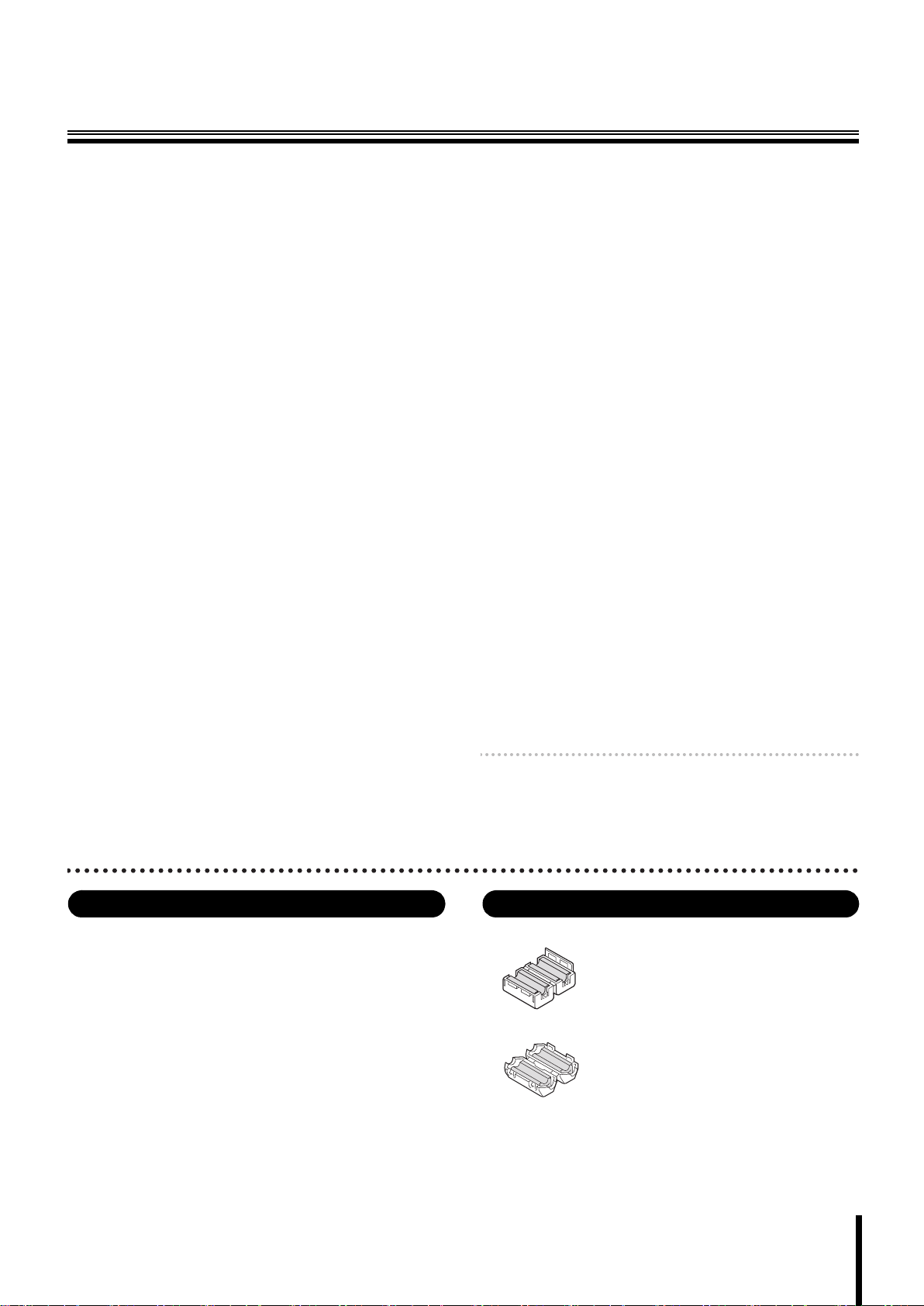
Expendable items Accessories
The following parts are expendable items. Be sure to replace them
after their work life has expired. Component performance cannot be
guaranteed when parts are used to the very end of their projected
work life. Durability will differ according to environmental conditions
and usage.
• Lens unit: about 20,000 hours (Motor: 1,200,000 operations)
• Slip ring: about 20,000 hours (1,200,000 rotations)
• Motor: about 33,000 hours (12,000,000 revolutions)
• Fan: about 30,000 hours
• Clamping core (large) x 2 (square type)
• Clamping core (small) x 1 (round type)
For installing the core, refer to the supplied installation manual.
2
Page 4
Precautions
■ In case of a problem
Do not use the unit if smoke or a strange odor comes from the
unit, or if it seems not to function correctly. Turn off the power
immediately and disconnect the power cord, and then consult
your dealer or an Authorized Sanyo Service Center.
■ Do not open or modify
Do not open the cabinet, as it may be dangerous and cause
damage to the unit. For repairs, consult your dealer or an
Authorized Sanyo Service Center.
■ Do not put objects inside the unit
Make sure that no metal objects or flammable substance get
inside the unit. If used with a foreign object inside, it could
cause a fire, a short-circuit or damage. Be careful to protect the
unit from rain, sea water, etc. If water or liquid gets inside the
unit, turn off the power immediately and disconnect the power
cord, and then consult your dealer or an Authorized Sanyo
Service Center.
■ Be careful when handling the unit
To prevent damage, do not drop the unit or subject it to strong
shock or vibration.
■ Do not install this unit close to magnetic fields
The magnetic fields may result in unstable operation.
■ Protect from humidity and dust
To prevent damage, do not install the unit where there is
greasy smoke or steam, where the humidity may get too high,
or where there is a lot of dust.
■ Protect from high temperatures
Do not install close to stoves, or other heat sources, such as
spotlights, etc., or where it could be subject to direct sunlight,
as this could cause deformation, discoloration or other
damage.
Be careful when installing close to the ceiling, in a kitchen or
boiler room, as the temperature may rise to high levels.
■ WEEE Symbol Information
Please note:
Your SANYO product is designed and
manufactured with high quality materials and
components which can be recycled and
reused.
This symbol means that electrical and
electronic equipment, at their end-of-life,
should be disposed of separately from your
household waste.
Please dispose of this equipment at your local
community waste collection/recycling centre.
In the European Union there are separate
collection systems for used electrical and
electronic products.
Please help us to conserve the environment
we live in!
This symbol mark and recycle system
are applied only to EU countries and
not applied to the countries in the
other area of the world.
■ Cleaning
• Dirt can be removed from the cabinet by wiping it with a soft
cloth. To remove stains, wipe with a soft cloth moistened with
a soft detergent solution and wrung dry, then dry by wiping
with a soft cloth.
• Do not use benzine, thinner or other chemical products on
the cabinet, as this may cause deformation and paint
peeling. Before using a chemical cloth, make sure to read all
accompanying instructions. Make sure that no plastic or
rubber material comes into contact with the cabinet for a long
period of time, as this may cause damage or paint peeling.
■ Installing the camera
To avoid injury, be sure to follow the installation manual to
install the camera on the ceiling (floor) or wall securely.
3
Page 5
Before Using the Menu
0 00 0 0
0 01 0 0
0 00 0 1
E sc t o e x i t
C A M 1 D V R 1
C A M 1 D V R 1
C A M 1 D V R 1
C A M E R A M E N U C O N T R O L
E sc t o e x i t
C A M 2 D V R 1
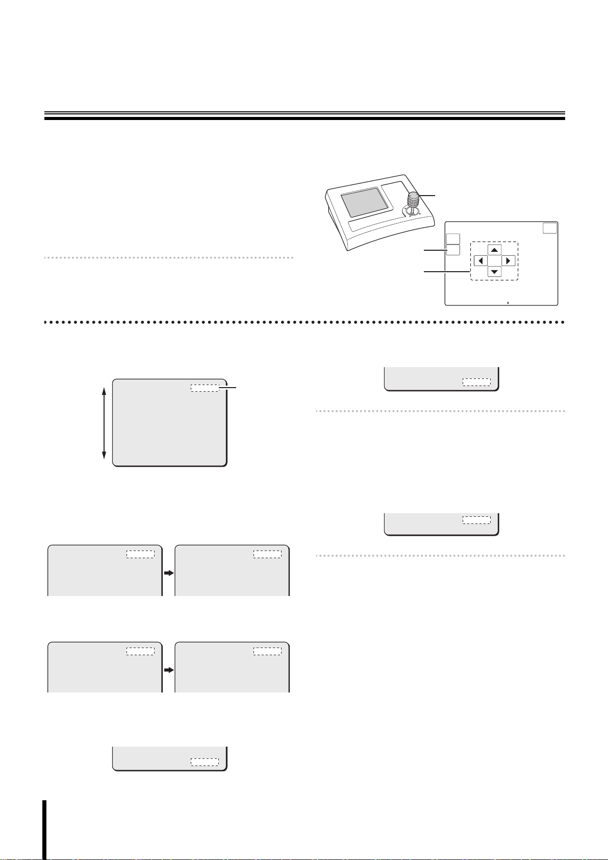
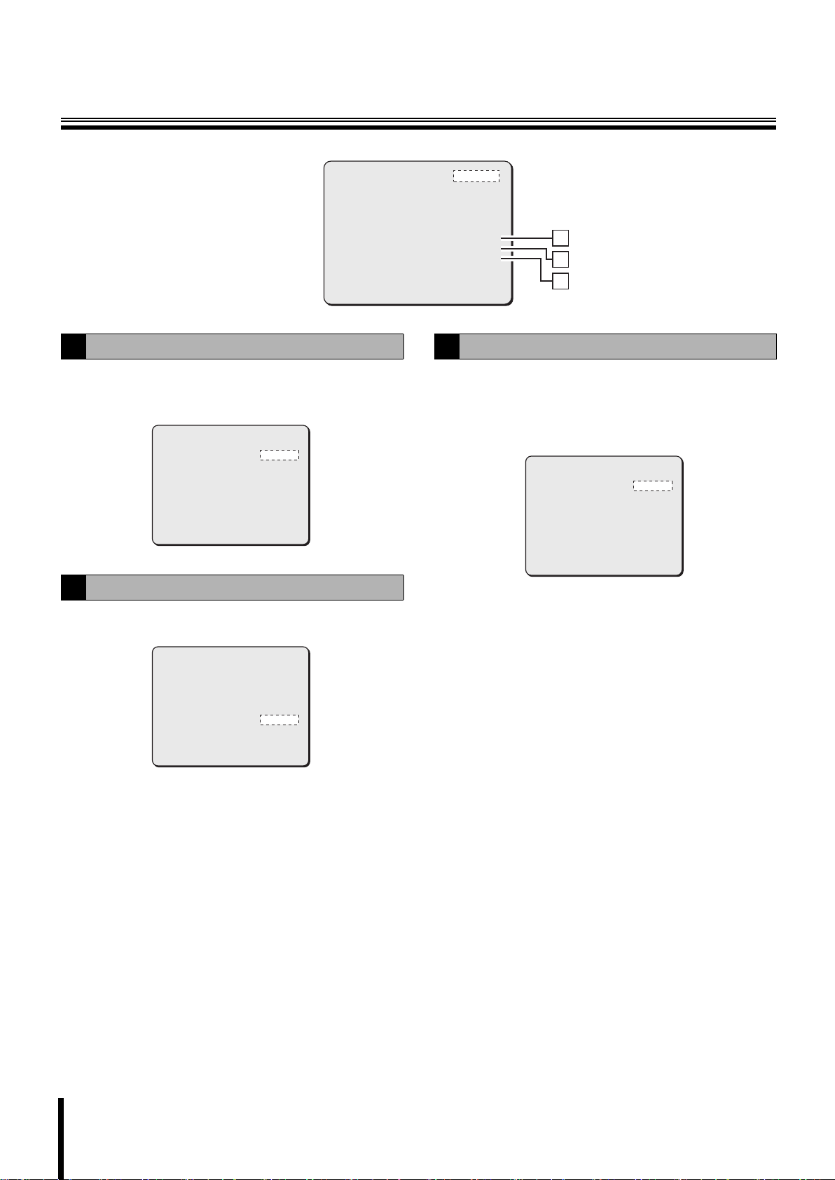
After installing the camera, use the menu to select camera operating options
and required functions according to your operating environment and
surveillance purpose. Use the system controller (VSP-9000) to perform menu
setting operations while viewing the menu on the monitor screen.
(The VAC-70 also can be used to operate the camera.)
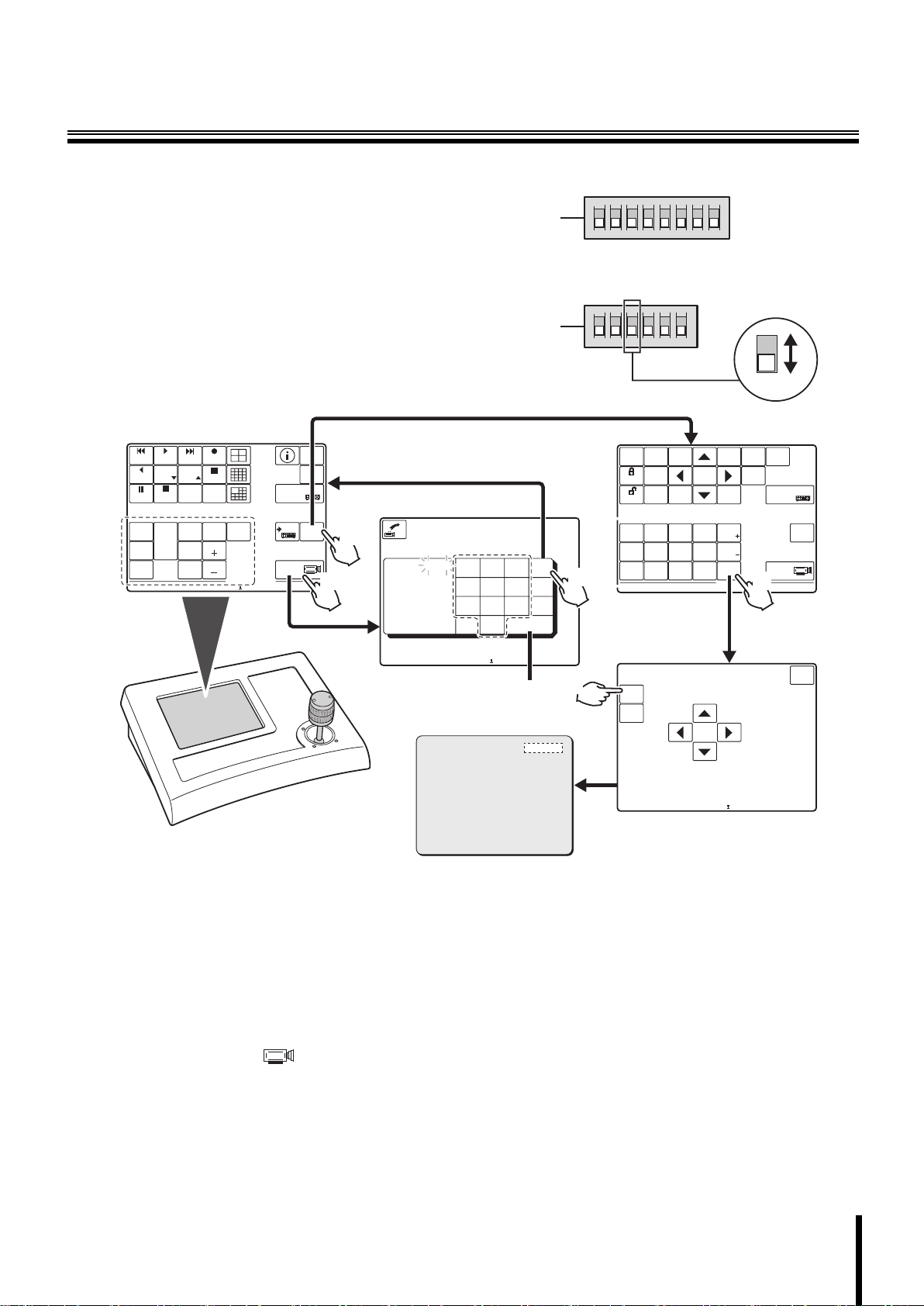
• To operate the system controller using the RS485 control method:
For system control setting switches (B), set the No.3 switch to the lower position
(OFF).
• To operate the system controller using the coaxial control method:
For system control setting switches (B), set the No.3 switch to the upper
position (ON).
<Main screen>
1
ALARM PLAY
PLAY
SPEED
R PLAY
PLAY STOP
STILL
SEQ
SEQ/
ON
PAN/
TOUR
PAN
OFF
ON
TOUR
ON
CAM 1 DVR 1
PLAY
SPEED
CLOCK
ADJUST
ONE PUSH
AF
FOCUS
FAR
FOCUS
NEAR
RECALARM
REC STOP
TIMER
ON/OFF
IRIS
CENTER
IRIS
IRIS
GO TO
PRESET
ADDRESS ?
MUX
ADDRESS ?
SYSTEM
SETUP
MAP
ENTER
DVR
TO SUB
SCREEN
2
5
?
1
Datum: 00000
00000
Accept.values
Max 00100
Min 00001
Digit
Camera nr.
123
456
78
.
0
ON
A
12345678
When setting the address of the
camera, use numbers higher
than or equal to 1.
ON
B
123456
<Sub screen>
MAIN
MONITOR
LOCK
UNLOCK
AWB
AWB
RESET
esc
del
4
PRESET
MEMORY
CAM 1 DVR 1
9
enter
ONOFF
ON
OFF
3
SEARCH
MON2
FR/FI
SEQUENCE
AUDIO
AUX
SET
AUX
OFF
ZOOM
PRESET
MENU
COPY
BLC
ON
ON
BLC
OFF
ZOOM
PRESET
OFF
ON
MENU
ZOOM
CHANNEL
RESET
TO
10 KEY
EXIT/OSD
ELS
L-L
ON
PHASE
ELS
L-L
OFF
PHASE
MENUCODE
ADDRESS ?
ADDRESS ?
DVR
TO MAIN
SCREEN
6
Make connections with all equipment and turn them on.
1
When the power is turned on, the camera will perform its
startup movements. The camera’s address and other
information will be displayed on the monitor screen. After the
startup movements have been completed, live image will be
displayed.
The main screen appears on the touch panel of the system
controller.
Press the [ADDRESS? ] button.
2
The address entering screen appears.
Enter the camera’s address using the 10 key
3
buttons, and press the [enter] button.
The address (camera number) entered here is the one
specified with the address setting switches (A) and is
displayed on the monitor screen during the startup
movements.
System controller
Esc to exit
CAM 1 DVR 1
3
<Menu screen>
CAMERA
LENS
PAN/TILT
AUTO MODE
PASSWORD
LANGUAGE
OPTION
ADVANCED MENU
PRESET
MENU
Monitor screen
SET
SET
SET
SET
SET
SET
SET
SET
OFF
END
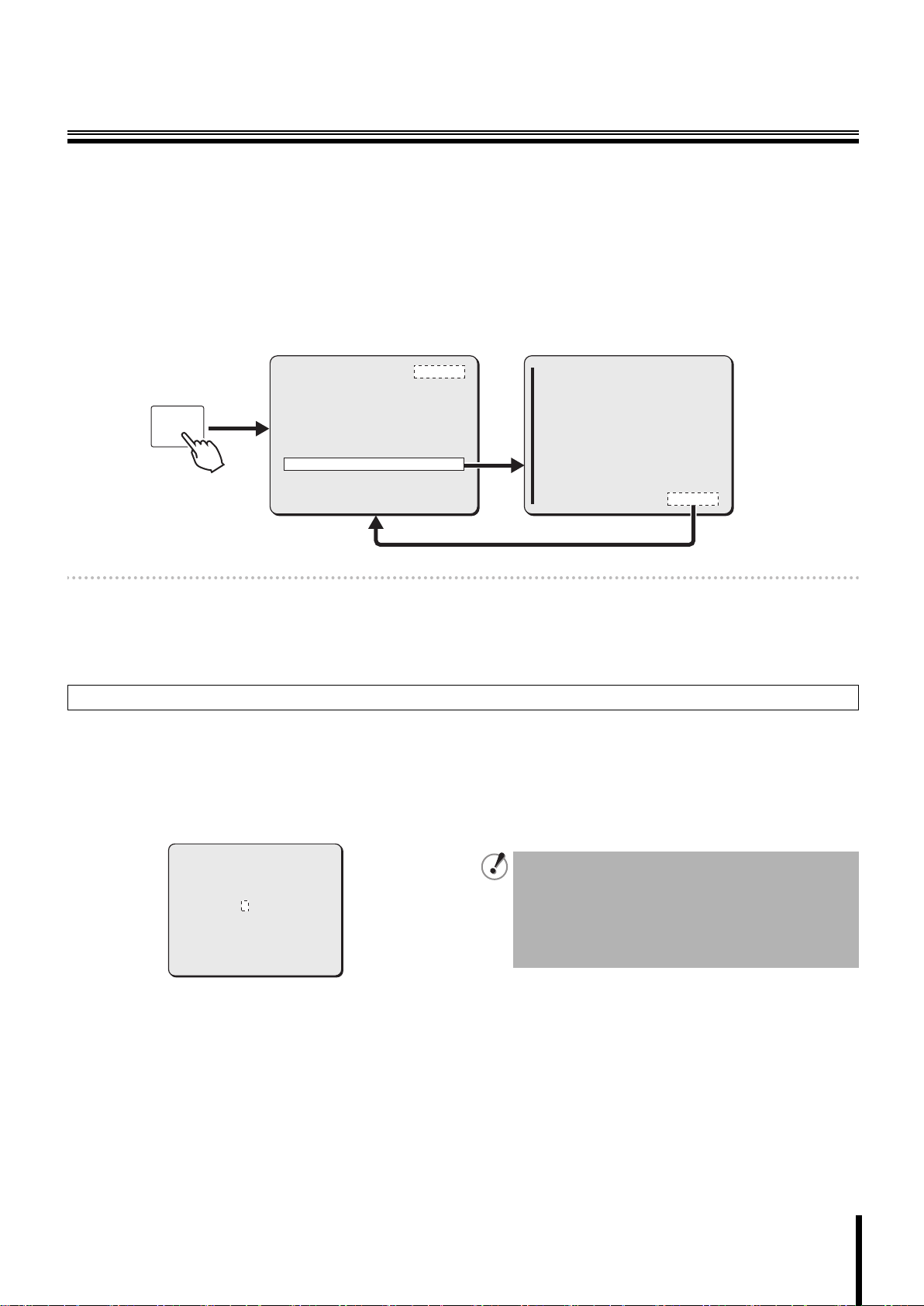
Press the [esc] button.
4
The main screen appears again.
Press the [TO SUB SCREEN] button.
5
The sub screen appears.
Press the [MENU] button in the sub screen.
6
The CAMERA MENU CONTROL screen appears.
Press the [MENU] button in the CAMERA MENU
7
CONTROL screen.
The camera menu appears on the monitor screen.
CAMERA MENU CONTROL
7
y
y
y
y
y
y
y
y
MENU
ENTER
Esc to exit
CAM 2 DVR 1
esc
4
Page 6
Basic Operations for Performing Settings in
C AME RA M E N U C O N T RO L
Es c t o e x
t CA M 2 D V R 1
the Menu
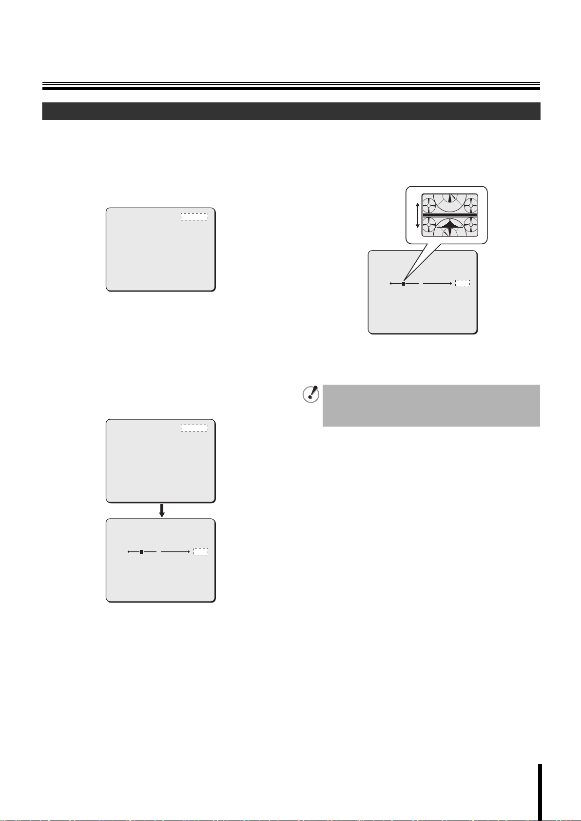
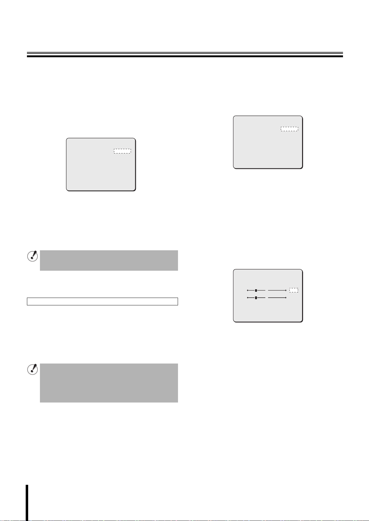
To perform settings in the menu, use the joystick lever (1) on the system controller and the [ENTER] button (2) in the CAMERA MENU
CONTROL screen.
• Joystick lever:
Used to move the cursor or select menu options.
Instead of the joystick lever, the control buttons shown in (3) in
the CAMERA MENU CONTROL screen can be used to move the
cursor or select menu options.
• [ENTER] button:
Used to confirm your selection or execute operation commands.
Memo: Some settings in the menu can be performed by using the
sub screen on the system controller. For details, refer to the
system controller instruction manual.
2
3
1
<CAMERA MENU
CONTROL screen>
CAMERA MENU CONTROL
MENU
ENTER
Esc to ex
it CAM 2 DVR 1
esc
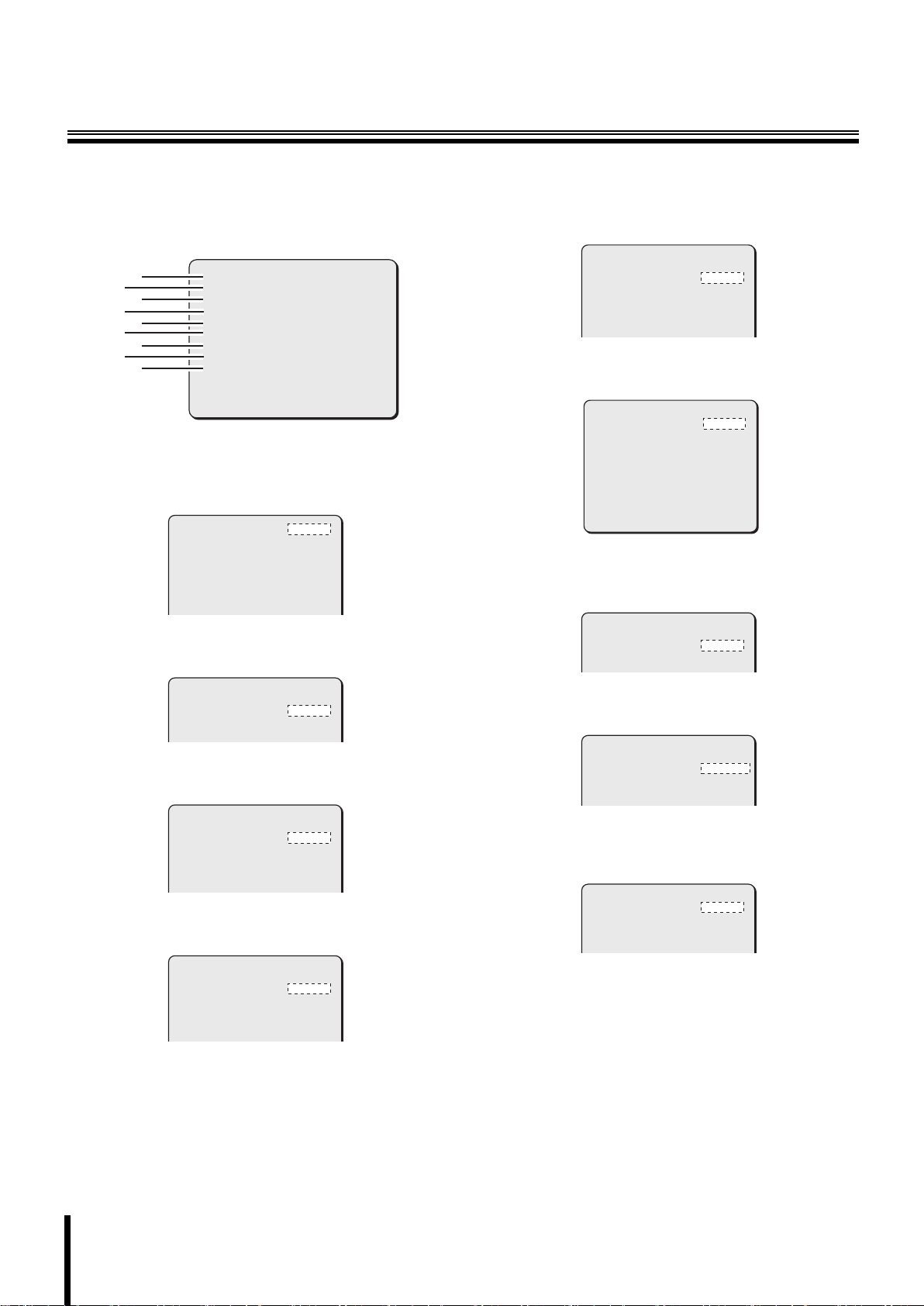
● To select the menu to perform settings
Use the joystick lever (xy) to move the cursor highlighting the menu
item up or down. Move the cursor to your desired menu item using
the lever.
CAMERA
LENS
PAN/TILT
AUTO MODE
ALARM
PRIVACY MASK
PASSWORD
LANGUAGE
OPTION
PRESET
MENU
SET
SET
SET
SET
SET
SET
SET
SET
SET
OFF
BACK
y
y
y
y
y
y
y
y
y
Cursor
● To display an advanced setting screen for the
selected menu
The menu item shown with y mark has an advanced setting screen.
After selecting the menu item with y mark, press the [ENTER] button
to display the advanced setting screen.
CAMERA y
LENS y
PAN/TILT y
AUTO MODE y
ALARM y
PRIVACY MASK y
PASSWORD y
SET
SET
SET
SET
SET
SET
SET
SYNC
IRIS y
WHITE BALANCE y
BLC
SHUTTER
APERTURE y
AGC y
INT
AUTO
ATW
OFF
OFF
ON
ON
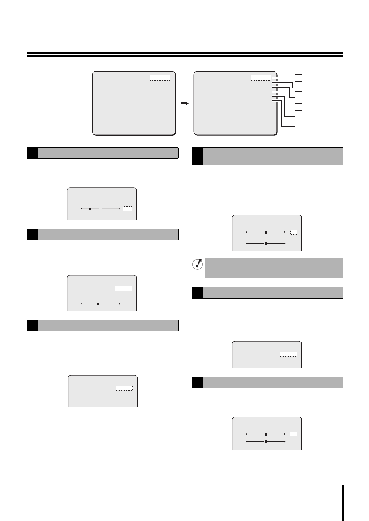
● To select an option for the setting item
Use the joystick lever (vw) to display the available options in turn.
SYNC
IRIS y
WHITE BALANCE y
BLC
SHUTTER
APERTURE y
AGC y
INT
AUTO
ATW
OFF
OFF
ON
ON
SYNC y
IRIS y
WHITE BALANCE y
BLC
SHUTTER
APERTURE y
AGC y
L-L
AUTO
ATW
OFF
OFF
ON
ON
● To exit from the menu screen
Move the cursor to “MENU” and select the “END” option, then press
the [ENTER] button.
PRESET
MENU
OFF
END
Memo: If there is no menu operation for three minutes or more, the
menu screen is automatically exited.
● To display the menu screen again
Press the [MENU] button in the CAMERA MENU CONTROL screen.
● To restore your selected options to initial values
Move the cursor to “PRESET” and change its option to “ON”, then
press the [ENTER] button.
PRESET
MENU
ON
BACK
Memo: The following settings cannot be restored.
•Privacy mask
• Preset position
• Camera view
• Camera title
• Password
☞ In this manual, xy represent vertical joystick lever operation
and vw represent horizontal joystick lever operation.
● To go back to a previous setting screen
Move the cursor to “MENU” and select the “BACK” option, then press
the [ENTER] button.
PRESET
MENU
OFF
BACK
5
Page 7
About Setting Menus
b Setting menu mode
For performing settings in the menu, the following two menu modes are available.
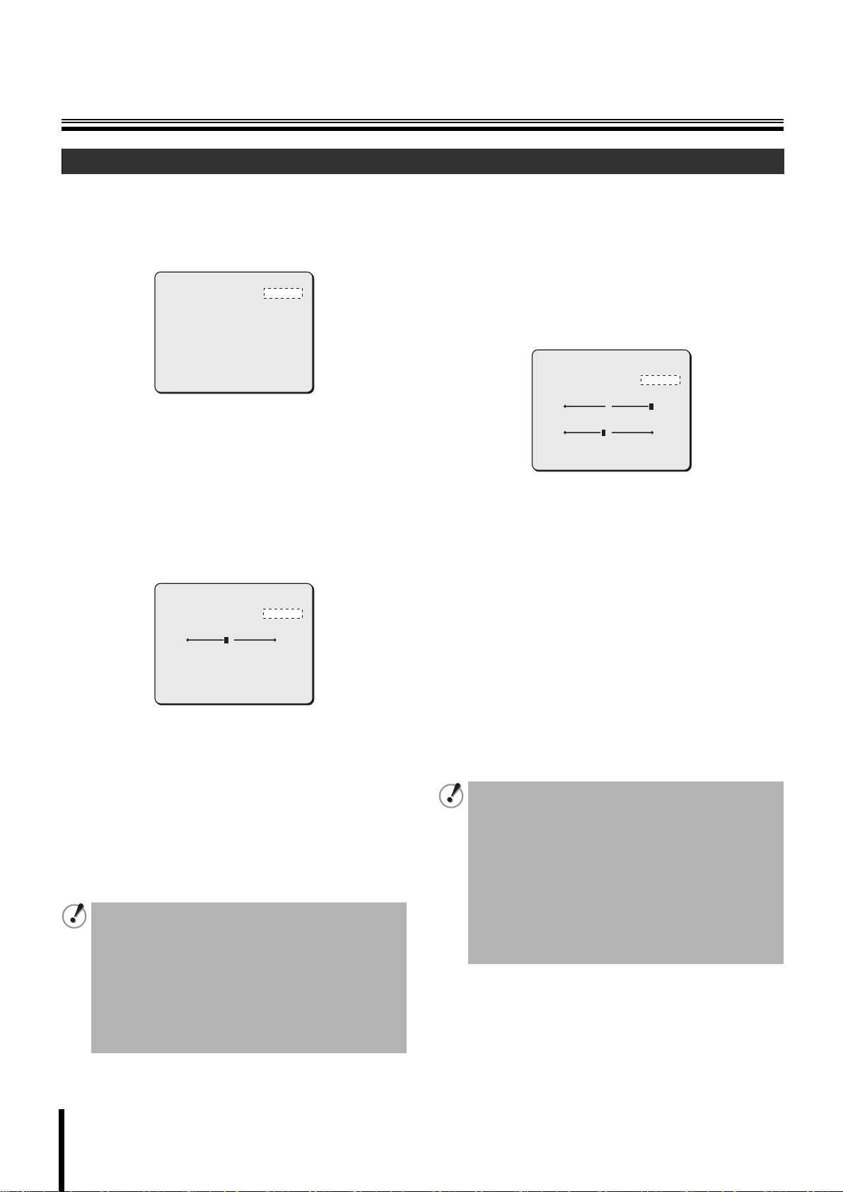
● Main menu
This menu, which is provided for general users, appears by pressing the [MENU] button in the CAMERA MENU CONTROL screen. Some menu
items and setting options, which are available in the advanced menu, are omitted in the main menu.
● Advanced menu
This menu, which is provided for administrative users, appears by selecting [ADVANCED MENU] in the main menu. In the advanced menu, the
menu items for the [ALARM] and [PRIVACY MASK] settings are added and advanced settings can be made on individual menu screens.
<Main menu> <Advanced menu>
MENU
CAMERA
LENS
PAN/TILT
AUTO MODE
PASSWORD
LANGUAGE
OPTION
ADVANCED MENU
PRESET
MENU
SET
SET
SET
SET
SET
SET
SET
SET
OFF
END
y
y
y
y
y
y
y
y
CAMERA y
LENS y
PAN/TILT y
AUTO MODE y
ALARM y
PRIVACY MASK y
PASSWORD y
LANGUAGE y
OPTION y
PRESET
MENU
SET
SET
SET
SET
SET
SET
SET
SET
SET
OFF
BACK
Memo: • In the advanced menu, the vertical line is displayed on the left end of the screen.
• The settings common to the main menu and advanced menu modes are shared regardless of the menu mode in which the settings are
made. However, different passwords can be specified for the main menu and advanced menu respectively.
☞ The description in this manual assumes the advanced menu.
Entering password
When the password lock is enabled, you have to enter your password before displaying the main menu by pressing the [MENU] button. To enter
your password, perform the following procedures.
Use the joystick lever (vw) to select the digit and
1
use the lever (
xy) to select a number.
The PASSWORD screen appears.
After entering your four-digit password, press
2
[ENTER].
If the password is authenticated, the menu screen appears.
**** y
MENU
PASSWORD
SET
BACK
• If an invalid password is entered, “NG” appears and
the cursor moves to [BACK]. If you entered invalid
password three consecutive times, the password
entry field disappears.
• The factory setting value for password is “1234”. To
keep the camera system secured, change your
password regularly.
6
Page 8
About Setting Menus
b Setting menu composition
The setting menu (ADVANCED MENU) contains the following
settings.
The menu item shown with y mark has an advanced setting
screen.
2
4
6
8
1
3
5
7
9
CAMERA y
LENS y
PAN/TILT y
AUTO MODE y
ALARM y
PRIVACY MASK y
PASSWORD y
LANGUAGE y
OPTION y
PRESET
MENU
1 Camera settings (CAMERA)
Performs camera shooting settings including synchronization, lens
aperture, white balance, backlight compensation and electronic
shutter.
SYNC
IRIS y
WHITE BALANCE y
BLC
SHUTTER
APERTURE y
AGC y
GAMMA
DAY/NIGHT y
2 Lens settings (LENS)
Performs settings for focus and zoom operations.
INT
AUTO
ATW
OFF
OFF
ON
ON
0.45
AUTO
SET
SET
SET
SET
SET
SET
SET
SET
SET
OFF
BACK
☞P8
5 Alarm settings (ALARM)
Performs settings including alarm input/output (external input x 8,
external output x 2) and motion sensor settings.
ALARM
ALARM IN y
ALARM OUT y
ALARM DISABLE
MOTION
ALARM DISPLAY
1
1
OFF
OFF
OFF
☞P38
6 Privacy mask settings (PRIVACY MASK)
Specifies up to 24 privacy masks to protect privacy.
MASK NO.SELECT
MASK 1
MASK 2
MASK 3
MASK 4
MASK 5
MASK 6
MASK 7
MASK 8
ªªª ººº
PRESET
MENU
OFF
OFF
OFF
OFF
OFF
OFF
OFF
OFF
OFF
BACK
☞P44
7 Password settings (PASSWORD)
Performs settings for enabling/disabling password lock and changing
password.
PASSWORD LOCK y
PASSWORD CHANGE y
PASSWORD
OFF
SET
☞P45
FOCUS y
ZOOM y
LENS
AUTO
SET
☞P22
3 Pan and tilt settings (PAN/TILT)
Performs panning and tilting settings including preset position setting.
PAN/TILT SETTING
PRESET POSITION y
PROPORTIONAL
FREEZE
SET NORTH
TILT LIMIT
SET
ON
OFF
OFF
OFF
☞P25
4 Auto mode settings (AUTO MODE)
Performs settings for three auto surveillance modes.
SEQUENCE y
AUTO PAN y
TOUR y
AUTO RETURN
TIME
AUTO MODE
A
1
1
SEQ A
1M
☞P33
8 Language settings (LANGUAGE)
Performs display language settings for menus.
LANGUAGE
LANGUE
SPRACHE
LANGUAGE
ENGLISH
FRENCH
GERMAN
☞P47
9 Miscellaneous settings (OPTION)
Performs miscellaneous settings including on-screen information and
the Auto Flip function.
INFORMATION y
AUTO FLIP
MIRROR
REFRESH y
OPTION
SET
ON
OFF
SET
☞P48
7
Page 9
Camera Settings (CAMERA)
CAMERA y
LENS y
PAN/TILT y
AUTO MODE y
ALARM y
PRIVACY MASK y
PASSWORD y
LANGUAGE y
OPTION y
PRESET
MENU
Adjusting synchronization signal (SYNC)
A
SET
SET
SET
SET
SET
SET
SET
SET
SET
OFF
BACK
Adjusts vertical synchronization signal for the camera.
• Internal synchronization (INT)
• Power source synchronization (L-L)
L-L SETTING
[V SYNC PHASE]
141
Setting lens aperture (IRIS)
B
+
☞P10
Sets lens aperture according to the luminance level of the target
object.
• Auto iris (AUTO)
• Manual iris (MANU)
IRIS SETTING
SENSE UP
40
Setting the white balance (WHITE BALANCE)
C
[LEVEL]
OFF
+
☞P11
Sets the white balance according to the shooting conditions.
• Auto trace white balance (ATW)
• One-push automatic white balance (AWC)
• Fixed white balance (3200/5600/FLUO)
• Manual white balance (MWB)
SYNC
IRIS y
WHITE BALANCE y
BLC
SHUTTER
APERTURE y
AGC y
GAMMA
DAY/NIGHT y
PRESET
MENU
Setting the backlight compensation level
D
(BLC)
INT
AUTO
ATW
OFF
OFF
ON
ON
0.45
AUTO
OFF
BACK
A
B
C
D
E
F
Sets the backlight compensation function to get clearer image in
backlight condition.
• Multi-spot evaluative metering (MULT)
• Center-weighted average metering (CENT)
• Multi-spot metering (MASK)
•OFF
BLC SETTING
[BLC WEIGHT]
7
7
[BRIGHT]
☞P14
The multi-spot metering (MASK) function is available
only when registering a view setting file in the CAMERA
VIEW screen (P27).
Setting the electronic shutter (SHUTTER)
E
Sets the appropriate shutter speed according to your surveillance
purpose.
• Fast shutter speed (SHORT)
• Slow shutter speed (LONG)
•OFF
ES SETTING
SHUTTER SPEED
50
☞P16
MASKING
ATW SETTING
---
☞P12
Setting the profile compensation (APERTURE)
F
Adjusts the profile of the target object horizontally or vertically.
•ON y
•OFF
APERTURE SETTING
H 8
V 8
☞P17
8
Page 10
Camera Settings (CAMERA)
Setting the AGC level (AGC)
G
Sets the AGC (Auto Gain Control) level in four grades.
• ON (four grades)
•OFF
GAIN SETTING
MAX GAIN
DNR
PRESET
MENU
NORMAL
OFF
OFF
BACK
SYNC
IRIS y
WHITE BALANCE y
BLC
SHUTTER
APERTURE y
AGC y
GAMMA
DAY/NIGHT y
PRESET
MENU
INT
AUTO
ATW
OFF
OFF
ON
ON
0.45
AUTO
OFF
BACK
Setting the Day/Night function (DAY/NIGHT)
I
Switches automatically between color mode and black and white
mode depending on the luminance of the object being monitored.
• Enabling the Day/Night function (AUTO)
• Using the color mode only (COLOR)
• Using the black and white mode only (B/W)
☞P17
G
H
I
D/N SETTING-AUTO
LEVEL
BURST
FOCUS
PRESET
MENU
MID
OFF
2
OFF
BACK
☞P19
Setting the gamma correction level (GAMMA)
H
Sets the gamma correction level to adjust the contrast or brightness
level in four grades.
SYNC
IRIS y
WHITE BALANCE y
BLC
SHUTTER
APERTURE y
AGC y
GAMMA
DAY/NIGHT y
PRESET
MENU
INT
AUTO
ATW
OFF
OFF
ON
ON
0.45
AUTO
OFF
BACK
☞P18
9
Page 11
Camera Settings (CAMERA)
A Adjusting synchronization signal (SYNC)
The camera allows you to choose the synchronization signal
adjustment method from the following options.
• Internal synchronization (INT) <Initial setting>
Uses internal signal in the camera to adjust synchronization.
• Power source synchronization (L-L)
Uses the power source frequency to adjust the vertical
synchronization phase.
SYNC
IRIS y
WHITE BALANCE y
BLC
SHUTTER
APERTURE y
AGC y
GAMMA
DAY/NIGHT y
PRESET
MENU
INT
AUTO
ATW
OFF
OFF
ON
ON
0.45
AUTO
OFF
BACK
The internal synchronization (INT) is used as an initial setting. In this
setting, the vertical synchronization tends to be unstable when
multiple cameras are connected through the camera switcher and the
camera to be monitored is switched. In this case, use the following
steps to adjust the vertical synchronization phase.
Use the joystick lever (yx) to select [SYNC], use the
1
lever (vw) to select “L-L”, and press the [ENTER]
button.
The L-L SETTING screen appears.
SYNC y
IRIS y
WHITE BALANCE y
BLC
SHUTTER
APERTURE y
AGC y
GAMMA
DAY/NIGHT y
PRESET
MENU
L-L
AUTO
ATW
OFF
OFF
ON
ON
0.45
AUTO
OFF
BACK
Use the joystick lever (vw) to adjust the value so
2
that the image on the monitor does not move up
and down when you use the camera switcher.
(Phase adjustment for vertical
synchronization)
L-L SETTING
[V SYNC PHASE]
141
PRESET
MENU
+
OFF
BACK
☞ After completing adjustment, use the lever to move the
cursor to [MENU] and select “BACK” or “END”.
Adjustment using power source synchronization is
available only for the area where the power supply
frequency is 50Hz. This setting will not work in the area
where the power supply frequency is 60Hz.
L-L SETTING
[V SYNC PHASE]
141
PRESET
MENU
+
OFF
BACK
10
Page 12
Camera Settings (CAMERA)
B Setting lens aperture (IRIS)
Sets lens aperture according to the luminance level of the target
object.
The following methods are available for setting lens aperture.
• Auto iris (AUTO) <Initial setting>
• Manual iris (MANU)
SYNC
IRIS
WHITE BALANCE
BLC
SHUTTER
APERTURE
AGC
GAMMA
DAY/NIGHT
PRESET
MENU
INT
AUTO
ATW
OFF
OFF
ON
ON
0.45
AUTO
OFF
BACK
y
y
y
y
y
b Auto iris (AUTO)
Automatic setting of lens aperture provides natural images even
outdoors where the luminance difference is large, or in backlight
conditions.
Use the joystick lever (xy) to select [IRIS], use the
1
lever (vw) to select “AUTO”, and press the [ENTER]
button.
The IRIS SETTING screen appears.
IRIS SETTING
SENSE UP
40
[LEVEL]
OFF
+
b Manual iris (MANU)
When the [IRIS] is set to “MANU”, lens aperture can be set manually.
Because activating the electronic iris disables the auto iris function,
you need to set appropriate lens aperture using the following
procedure.
Use the joystick lever (xy) to select [IRIS], use the
1
lever (vw) to select “MANU”, and press the [ENTER]
button.
The IRIS SETTING screen appears.
IRIS SETTING
EI
[IRIS STOP]
17
[LEVEL]
40
PRESET
MENU
Use the joystick lever (xy) to select [EI] and use the
2
lever (vw) to select “ON”.
The electronic iris function controls both the AGC circuit and
shutter speed to change exposure value.
Use the joystick lever (xy) to select [IRIS STOP]
3
and use the lever (vw) to adjust the aperture
opening value.
Selecting the value changes the lens aperture opening.
Available settings: 1 (close, darker) - 17 (open, brighter)
OFF
+
+
OFF
BACK
PRESET
MENU
Use the joystick lever (xy) to select [SENSE UP]
2
and use the lever (vw) to select magnification
OFF
BACK
power of electronic sensitivity.
Available settings: OFF, X2, X4, X8, X16, X32
Use the joystick lever (xy) to select [LEVEL] and
3
use the lever (vw) to adjust the iris level.
Available settings: 0 (dark) - 100 (bright)
☞ After completing setting, use the lever to move the cursor to
[MENU] and select “BACK” or “END”.
• Electronic sensitivity boosting (SENSE UP)
automatically lengthens the CCD exposure time in
dark situations. Accordingly, moving target objects
may cause conspicuous afterimages, blurs and white
spots.
• When electronic sensitivity boosting (SENSE UP) is
enabled, the electronic shutter function will not work.
• When the Day/Night function is set to “AUTO”,
electronic sensitivity boosting (SENSE UP) works
only while black and white image is displayed.
Use the joystick lever (xy) to select [LEVEL] and
4
use the lever (vw) to adjust the iris level.
Available settings: 0 (video level is darker) - 100 (video level
is brighter)
☞ After completing setting, use the lever to move the cursor to
[MENU] and select “BACK” or “END”.
Notes on setting electronic iris (EI):
• If the iris views an unusually bright image, it can
cause a smear that cannot be corrected by adjusting
the light entering through the lens. In this case,
arrange the physical angle of lighting in a way that will
prevent on-screen smearing.
• If there is a fluorescent lighting in the camera
location, flickering of the target object may occur.
Changing fluorescent lighting to incandescent
lighting will prevent the flickering.
• When the electronic iris (EI) is activated, the
electronic shutter (SHUTTER) setting cannot be made.
11
Page 13
Camera Settings (CAMERA)
C Setting the white balance (WHITE BALANCE)
Sets the white balance according to the shooting conditions.
The following methods are available for setting white balance.
• Auto trace white balance (ATW) <Initial setting>
• One-push automatic white balance (AWC)
• Fixed white balance (3200/5600/FLUO)
• Manual white balance (MWB)
SYNC
IRIS
WHITE BALANCE
BLC
SHUTTER
APERTURE
AGC
GAMMA
DAY/NIGHT
PRESET
MENU
INT
AUTO
ATW
OFF
OFF
ON
ON
0.45
AUTO
OFF
BACK
y
y
y
y
y
b Auto trace white balance (ATW)
Even when light sources of the target object change, automatic
adjustment assures capture of most suitable colors.
Use the joystick lever (xy) to select [WHITE BALANCE] and use the
lever (vw) to select “ATW y”.
Auto trace white balance settings are completed when “ATW y” is
selected. When an extremely bright light source is in the target
object, use the mask pattern so that the light source will not be
detected.
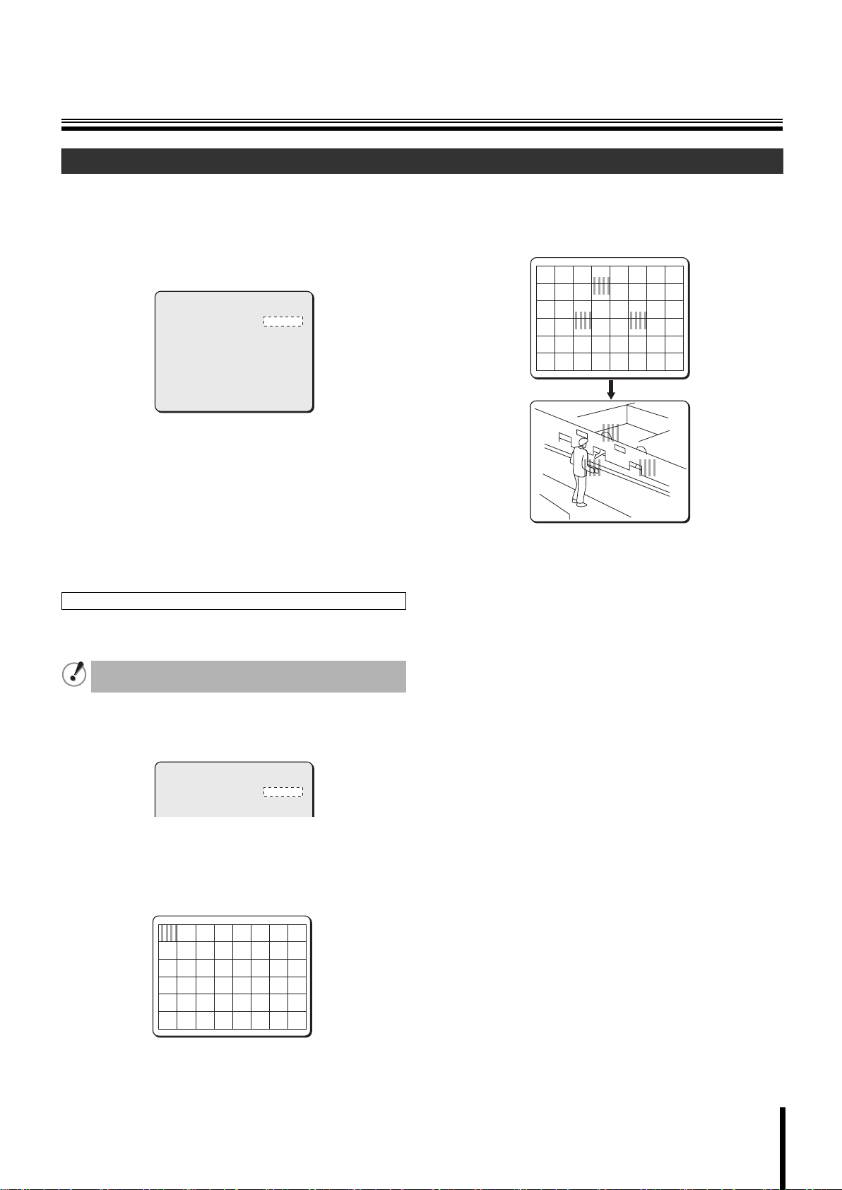
Placing mask patterns
To place a mask pattern over specific light sources in the target
object, do the following.
Mask patterns can be placed only when registering a
view setting file in the CAMERA VIEW screen.
While “ATW y” is selected by using the joystick
1
lever (vw), press the [ENTER] button.
The ATW SETTING screen appears.
Use the joystick lever (xy or vw) to move a mask
3
pattern to the light source area to be masked, and
press the [ENTER] button.
This sets the mask pattern.
ATW MASKING
CONTINUE (y)
If you want additional mask patterns to be placed, repeat the
above procedure.
<To delete the mask pattern>
Use the joystick lever (xy or vw) to place a mask pattern over
the mask pattern to be cancelled, then press the [ENTER]
button.
Use the joystick lever (y) to move a mask pattern to
4
the bottom area of the screen and continue holding
the lever straight down for three seconds.
This completes the mask pattern setting procedure.
☞ After completing setting, use the lever to move the cursor to
[MENU] and select “BACK” or “END”.
ATW SETTING
MASKING y
Use the joystick lever (xy) to select [MASKING],
2
use the lever (vw) to select “ON y”, and press the
ON
[ENTER] button.
The ATW MASKING screen appears. A mask pattern is
displayed in the top left of the screen.
ATW MASKING
CONTINUE (y)
12
Page 14
Camera Settings (CAMERA)
b One-push automatic white balance
(AWC)
In one-push automatic white balance setting, adjust white balance for
a fixed surveillance location by orienting the lens toward the white
target object (ex. white wall or paper).
Use the joystick lever (xy) to select [WHITE
1
BALANCE], use the lever (vw) to select “AWC y”,
and press the [ENTER] button.
The AWC SETTING screen appears.
AWC SETTING
AWC LOCK y
GO TO MWB y
MENU
While “SET y” for [AWC LOCK] is highlighted,
2
orient the lens toward the white target object and
press the [ENTER] button.
After the highlighted “SET y” option temporarily returns to
normal indication for about two seconds, the “SET y” option is
highlighted again and the white balance adjustment
completes.
If the result of white balance adjustment is
unsatisfactory, press the [ENTER] button again while
“SET y” is highlighted.
☞ After completing setting, use the lever to move the cursor to
[MENU] and select “BACK” or “END”.
Fine-tuning white balance setting (GO TO MWB)
If you want to fine-tune white balance setting after one-push
automatic white balance adjustment completes, you can adjust white
balance manually. To adjust white balance manually, use the joystick
lever (xy) to select [GO TO MWB] – “SET y”, and press the [ENTER]
button.
The MWB SETTING screen appears.
For details on adjusting white balance manually, refer to the “Manual
white balance (MWB)” section in the right column on this page.
You also can access the MWB SETTING screen directly
by selecting “MWB y” in the [WHITE BALANCE] menu
item. Whether you access the MWB SETTING screen
directly or through the AWC SETTING screen, only one
set of options and values in the MWB SETTING screen is
stored as the manual white balance setting.
SET
SET
BACK
b Fixed white balance (3200/5600/FLUO)
You can set the color temperature of white balance setting to a fixed
value.
Use the joystick lever (xy) to select [WHITE
1
BALANCE] and use the lever (vw) to select desired
color temperature option.
SYNC
IRIS
WHITE BALANCE
BLC
SHUTTER
APERTURE
AGC
GAMMA
DAY/NIGHT
PRESET
MENU
Available settings:
• 3200: Color temperature of 3,200K (For indoor)
• 5600: Color temperature of 5,600K (For outdoor)
•FLUO: Color temperature of 4,200K (For fluorescent
lighting)
INT
AUTO
3200
OFF
OFF
ON
ON
0.45
AUTO
OFF
BACK
y
y
y
y
b Manual white balance (MWB)
You can manually adjust white balance to your desired setting.
Use the joystick lever (xy) to select [WHITE
1
BALANCE], use the lever (vw) to select “MWB y”,
and press the [ENTER] button.
The MWB SETTING screen appears.
MWB SETTING
R 64
B 64
PRESET
MENU
Use the joystick lever (xy) to select color and use
2
the lever (vw) to adjust darkness level for the color.
Available settings: R (Red), B (Blue)
Available settings: 0 - 255 (The larger the number, the
☞ After completing setting, use the lever to move the cursor to
[MENU] and select “BACK” or “END”.
+
+
OFF
BACK
darker the color is.)
13
Page 15
Camera Settings (CAMERA)
D Setting the backlight compensation level (BLC)
Sets the backlight compensation function to get clearer image in
backlight condition.
The following metering methods are available for the backlight
compensation function.
• Multi-spot evaluative metering (MULT)
• Center-weighted average metering (CENT)
• Multi-spot metering (MASK)
SYNC
IRIS
WHITE BALANCE
BLC
SHUTTER
APERTURE
AGC
GAMMA
DAY/NIGHT
PRESET
MENU
INT
AUTO
ATW
MULT
OFF
ON
ON
0.45
AUTO
OFF
BACK
y
y
y
y
y
y
• If you do not use the backlight compensation
function, set [BLC] to “OFF”.
• The multi-spot metering (MASK) function is available
only when registering a view setting file in the
CAMERA VIEW screen (P27).
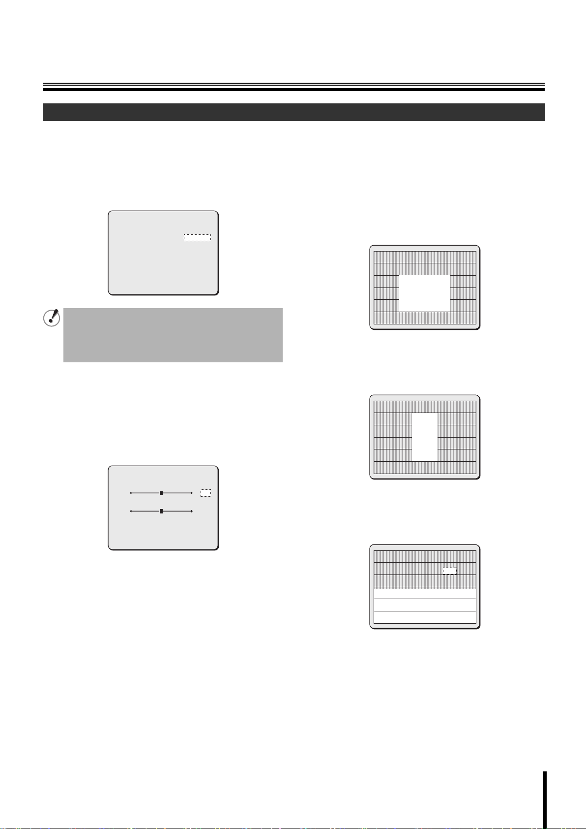
b Multi-spot evaluative metering (MULT)
Evaluates the entire screen and corrects according to the best image
obtained.
Use the joystick lever (xy) to select [BLC], use the
1
lever (vw) to select “MULT y”, and press the
[ENTER] button.
The BLC SETTING screen appears.
b Center-weighted average metering
(CENT)
Measures light mainly at the specified metering zone and
compensates for brightness level according to the best image
obtained.
Use the joystick lever (xy) to select [BLC], use the
1
lever (vw) to select “CENT y”, and press the
[ENTER] button.
The BLC SETTING (POSITION) screen appears.
BLC SETTING
[POSITION]
Use the joystick lever to determine the position for
2
the center-weighted average metering zone, and
press the [ENTER] button.
The BLC SETTING (SIZE) screen appears.
BLC SETTING
[SIZE]
BLC SETTING
[BLC WEIGHT]
7
7
PRESET
MENU
Use the joystick lever (xy) to select [BLC WEIGHT]
2
and use the lever (vw) to select the value of “BLC
[BRIGHT]
OFF
BACK
WEIGHT”.
Available settings: 0 - 15 (The larger the number, the more
Use the joystick lever (xy) to select [BRIGHT] and
3
use the lever (vw) to adjust compensation level.
Adjusts the compensation level for the brightness of the
backlighting.
Available settings: 0 - 15 (The larger the number, the more it
backlighting works.)
brightens.)
☞ After completing setting, use the lever to move the cursor to
[MENU] and select “BACK” or “END”.
Use the joystick lever to determine the size of the
3
center-weighted average metering zone, and press
the [ENTER] button.
The BLC WINDOW WEIGHTING screen appears.
BLC WINDOW WEIGHTING
TOP
BOTTOM
LEFT
RIGHT
CENTER[FIX]
PRESET
MENU
0
0
0
0
7
OFF
BACK
14
Page 16
Camera Settings (CAMERA)
Use the joystick lever (xy) to select a zone to be
4
weighted and use the lever (vw) to adjust
weighting.
Selecting a zone to be weighted shows the corresponding
zone on the screen.
•TOP •BOTTOM
•LEFT •RIGHT
• CENTER [FIX] (The value is fixed to “7”.)
Available settings: 0 - 7 (The larger the number, the higher
the weighting.)
☞ After completing setting, use the lever to move the cursor to
[MENU] and select “BACK” or “END”.
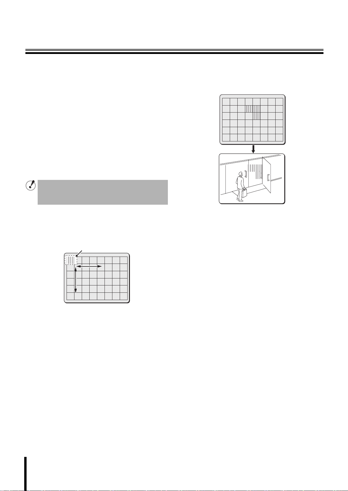
b Multi-spot metering (MASK)
Sets backlight compensation by masking the bright area of the
background using mask patterns.
The multi-spot metering (MASK) function is available
only when registering a view setting file in the CAMERA
VIEW screen (P27).
Set [MASKING] to “ON” in the MOTION SETTING screen.
Use the joystick lever (xy) to select [BLC], use the
1
lever (vw) to select “MASK y”, and press the
[ENTER] button.
The BLC MASKING screen appears. A mask pattern is
displayed in the top left of the screen.
Mask pattern
BLC MASKING
Use the joystick lever (xy or vw) to move a mask
2
pattern to the area to be excluded in metering, and
press the [ENTER] button.
This sets the mask pattern for the area to be excluded in
metering.
BLC MASKING
CONTINUE (y)
If you want additional mask patterns to be set, repeat the
above procedure.
<To delete the mask pattern>
Use the joystick lever (xy or vw) to place a mask pattern over
the mask pattern to be cancelled, then press the [ENTER]
button.
Use the joystick lever (y) to move a mask pattern to
3
the bottom area of the screen and continue holding
the lever straight down for three seconds.
This completes the mask pattern setting procedure.
CONTINUE (y)
☞ After completing setting, use the lever to move the cursor to
[MENU] and select “BACK” or “END”.
15
Page 17
Camera Settings (CAMERA)
E Setting the electronic shutter (SHUTTER)
Sets the appropriate shutter speed according to your surveillance
purpose.
The following shutter speed modes are available.
• Fast shutter speed (SHORT)
• Slow shutter speed (LONG)
SYNC
IRIS
WHITE BALANCE
BLC
SHUTTER
APERTURE
AGC
GAMMA
DAY/NIGHT
PRESET
MENU
INT
AUTO
ATW
OFF
SHORT
ON
ON
0.45
AUTO
OFF
BACK
y
y
y
y
y
y
If you do not use the electronic shutter, set [SHUTTER] to “OFF”.
The electronic shutter cannot be set in the following
conditions.
• For the auto iris setting, the electronic sensitivity
setting is activated. (When the [IRIS] is set to “AUTO”,
[SENSE UP] in the IRIS SETTING screen is set to other
than “OFF”.)
• For the manual iris setting, the electronic iris is
activated. (When the [IRIS] is set to “MANU”, [EI] is
set to “ON”.)
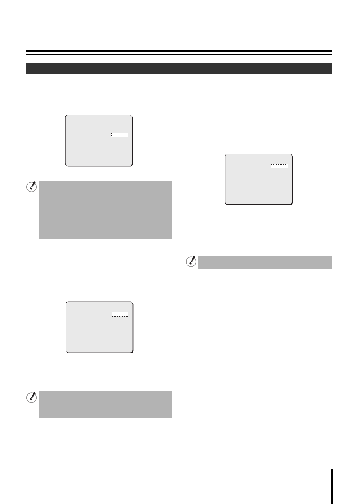
b Fast shutter speed (SHORT)
When viewing fast-moving target objects, higher shutter speed
produces clearer images with less blurs.
Use the joystick lever (xy) to select [SHUTTER],
1
use the lever (vw) to select “SHORT y”, and press
the [ENTER] button.
The ES SETTING screen appears.
b Slow shutter speed (LONG)
When the target object is in dark condition, making the exposure time
longer increases sensitivity, enabling you to view target object more
brightly. Select desired shutter speed according to the shooting
conditions.
The initial setting for slow shutter spped (LONG) is “x1”.
Use the joystick lever (xy) to select [SHUTTER],
1
use the lever (vw) to select “LONG y”, and press
the [ENTER] button.
The ES SETTING screen appears.
ES SETTING
SHUTTER SPEED
PRESET
MENU
Use the joystick lever (vw) to select the desired
2
shutter speed.
Available settings: x1, x2, x4, x8, x16, x32
(Each option represents a multiple of field
time. The higher the number, the longer
the exposure time.)
When the exposure time is longer, moving objects may
cause conspicuous afterimages, blurs and white spots.
☞ After completing setting, use the lever to move the cursor to
[MENU] and select “BACK” or “END”.
x1
OFF
BACK
ES SETTING
SHUTTER SPEED
PRESET
MENU
Use the joystick lever (vw) to select the desired
2
shutter speed.
50
OFF
BACK
Available settings: 50, 120, 250, 500, 1000, 2000, 4000,
10000 (1/N sec.)
To avoid flicker
If the camera is installed under fluorescent lighting and
the power supply frequency is 60Hz, set the shutter
speed to “120 (1/120 sec)” to avoid flicker.
☞ After completing setting, use the lever to move the cursor to
[MENU] and select “BACK” or “END”.
16
Page 18

Camera Settings (CAMERA)
Setting the profile compensation
F
(APERTURE)
Further emphasizes the profile of the target object. The amount of
compensation can be adjusted for the horizontal or vertical directions.
SYNC
IRIS
WHITE BALANCE
BLC
SHUTTER
APERTURE
AGC
GAMMA
DAY/NIGHT
PRESET
MENU
Use the joystick lever (xy) to select [APERTURE],
1
use the lever (vw) to select “ON y”, and press the
INT
AUTO
ATW
OFF
OFF
ON
ON
0.45
AUTO
OFF
BACK
y
y
y
y
y
[ENTER] button.
The APERTURE SETTING screen appears.
APERTURE SETTING
H 8
V 8
PRESET
MENU
OFF
BACK
G Setting the AGC level (AGC)
Sets the AGC (Auto Gain Control) level in four grades.
SYNC
IRIS
WHITE BALANCE
BLC
SHUTTER
APERTURE
AGC
GAMMA
DAY/NIGHT
If you do not use the AGC function, set [AGC] to “OFF”.
Setting AGC
Use the joystick lever (xy) to select [AGC], use the
1
lever (vw) to select “ON y”, and press the [ENTER]
button.
The GAIN SETTING screen appears.
GAIN SETTING
MAX GAIN
DNR
Memo: Auto Gain Control (AGC) is a function that automatically adjusts gain
level in the amplifier section for the camera’s video signal according
to the brightness of the target object and keeps the signal output level
constant. When the target object is bright, the gain level is
decreased; when it is dark, the level is increased.
INT
AUTO
ATW
OFF
OFF
ON
ON
0.45
AUTO
NORMAL
OFF
y
y
y
y
y
Available settings:
•OFF: The profile compensation is turned off.
•ON: The profile compensation is turned on.
Use the joystick lever (vw) to adjust the value for
2
“H” (horizontal).
Available settings: 1 - 15 (The higher the number, the further
the profile is emphasized.)
Use the joystick lever (xy) to move the cursor to
3
“V” (vertical), and use the lever (vw) to adjust the
value for “V”.
Available settings: 1 - 15 (The higher the number, the further
the profile is emphasized.)
☞ After completing adjustment, use the lever to move the
cursor to [MENU] and select “BACK” or “END”.
Use the joystick lever (xy) to select [MAX GAIN]
2
and use the lever (vw) to adjust AGC level.
Available settings:
•NORMAL: Initial setting
• MIDDLE: For dark target object
•HIGH: For very dark target object
•LOW: For bright target object
Memo: • The “LOW” option cannot be selected when the Day/Night
function is set to “AUTO”.
• The value for the “MAX GAIN” setting depends on the
Day/Night function mode.
• When the gain level is increased, the sensitivity is
improved in dark condition, but the noise level increases.
Use the joystick lever (xy) to select [DNR] and use the
3
lever (
vw
) to select a DNR (Digital Noise Reduction) option.
Available settings:
•ON: Applies DNR.
(Reduces noise during low luminance level.)
•OFF: Does not apply DNR.
Digital noise reduction operates when the gain level increases. In
addition, blurring and ghosting of images can occur when
moving images are monitored, so the resolution is also reduced
slightly.
When the electronic zoom is operating in the color mode, the
DNR (Digital Noise Reduction) does not function.
17
☞ After completing setting, use the lever to move the cursor to
[MENU] and select “BACK” or “END”.
Page 19

Camera Settings (CAMERA)
Setting the AGC level manually
When the AGC function is set to “OFF”, the gain level for camera’s
video signal can be specified manually.
Use the joystick lever (xy) to select [AGC], use the
1
lever (vw) to select “OFF”, and press the [ENTER]
button.
The GAIN SETTING screen appears.
GAIN SETTING
0dB
PRESET
MENU
Use the joystick lever (vw) to select the gain level
2
value.
Available settings: 0 - 30dB (The higher the number, the
more the gain level is increased.)
• When the Day/Night function is set to “AUTO”, the
AGC function cannot be set to “OFF”.
• The “AGC” can be set to “OFF” only when [SENSE
UP] in the IRIS SETTING screen is set to “OFF”.
OFF
BACK
Setting the gamma correction level
H
(GAMMA)
Sets the gamma correction level to adjust the contrast or
brightness level in four grades.
SYNC
IRIS
WHITE BALANCE
BLC
SHUTTER
APERTURE
AGC
GAMMA
DAY/NIGHT
PRESET
MENU
Use the joystick lever (xy) to select [GAMMA] and
1
use the lever (vw) to adjust the gamma correction
INT
AUTO
ATW
OFF
OFF
ON
ON
0.45
AUTO
OFF
BACK
y
y
y
y
y
level.
Available settings:
• 0.45: γ= 0.45
•1: γ= 1
•MODE1: Increases the contrast of the dark parts.
•MODE2: Further increases the contrast of the dark parts.
When “MODE1” or “MODE2” is selected, the image can
be too bright depending on the target object.
☞ After completing setting, use the lever to move the cursor to
[MENU] and select “BACK” or “END”.
☞ After completing setting, use the lever to move the cursor to
[MENU] and select “BACK” or “END”.
18
Page 20

Camera Settings (CAMERA)
I Setting the Day/Night function (DAY/NIGHT)
Switches automatically between color mode and black and white
mode depending on the luminance of the object being
monitored. This function lets you set the filming mode to color
mode during times of normal brightness like daytime or to black
and white mode during times of darkness like night.
• Enabling the Day/Night function (AUTO)
• Using the color mode only (COLOR)
• Using the black and white mode only (B/W)
SYNC
IRIS
WHITE BALANCE
BLC
SHUTTER
APERTURE
AGC
GAMMA
DAY/NIGHT
PRESET
MENU
• A sound from the camera may be heard when the
color image or black and white image is switched.
Also, the image will be distorted as shown in the
figure below. This is normal and does not indicate a
problem.
• If the power is turned off in the black and white mode
and the power is turned on again, the color mode will
be used. The focused position may be differently
adjusted between the color mode and the black and
white mode. Adjust focusing so that the focused
position matches between the color mode and the
black and white mode.
• When using infrared lighting in black and white mode,
if there is a strong reflection on the subject, the black
and white mode may switch to color mode. Use only
enough infrared lighting so that the mode is not
switched.
INT
AUTO
ATW
OFF
OFF
ON
ON
0.45
AUTO
OFF
BACK
y
y
y
y
y
(For VCC-MC600P only)
b Setting the Day/Night function (AUTO)
This function automatically switches between the color mode and the
black and white mode according to the luminance of the target object.
The color mode is used for daytime; the black and white mode is
used for night.
Use the joystick lever (xy) to select [DAY/NIGHT],
1
use the lever (vw) to select “AUTO y”, and press
the [ENTER] button.
The D/N SETTING-AUTO screen appears.
D/N SETTING-AUTO
LEVEL
BURST
FOCUS
Use the joystick lever (xy) to select [LEVEL], use
2
the lever (vw) to select a luminance level where the
viewing mode between the color mode and black
and white mode is switched, and press the [ENTER]
button.
Available settings:
•MID: The mode switches when the luminance of the
objects being monitored is between the “LOW” and
“HIGH” levels.
•HIGH:The mode switches when the luminance of the
•
•LOW: The mode switches when the luminance of the
<The LEVEL SETTING screen under the “ADJ” option>
1 COLOR → B/W
2 B/W → COLOR
objects being monitored is comparatively bright (the
black and white mode is used longer).
ADJy: Sets the switching luminance level manually.
When you select “ADJy”, the LEVEL SETTING
screen appears allowing you to perform manual
settings for the switching luminance level.
objects being monitored is comparatively dark (the
color mode is used longer).
LEVEL SETTING
[COLORwB/W]
1
[B/WwCOLOR]
1
Sets the luminance level for switching from the color mode
to the black and white mode.
Available settings: 1 - 7 (The larger the value, the darker
the switching luminance level.)
Sets the luminance level for switching from the black and
white mode to the color mode.
Available settings: 1 - 7 (The larger the value, the
brighter the switching luminance
level.)
MID
OFF
2
1
2
19
Memo: • In the “ADJ” setting, changing the setting for one of the
switching level settings (from color mode to black and
white mode or from black and white mode to color mode)
causes the other setting to change also.
• Increasing the luminance level difference avoids hunting
under IR (infrared) lighting.
Page 21

Camera Settings (CAMERA)
Use the joystick lever (xy) to select [BURST] and
3
use the lever (vw) to select “ON/OFF”.
If the camera is connected to peripheral devices like frame
switcher, burst may occur when the viewing mode is switched
between the color mode and the black and white mode. In this
case, compensate for the image by inserting the color burst
signals.
In general, set this option to “OFF”.
Available settings:
•ON: The color burst signal is turned on.
•OFF: The color burst signal is turned off.
Use the joystick lever (xy) to select [FOCUS] and
4
use the lever (vw) to select the focus compensation
mode.
In general, set this option to “2”. If images are out of focus, set
this option to “1”.
Available settings:
•1: Near-infrared wavelength correction (around 900nm) is
set during the black and white mode.
•2: Visible light spectrum is set during the color mode.
☞ After completing setting, use the lever to move the cursor to
[MENU] and select “BACK” or “END”.
While the Day/Night function is set to “AUTO”, the
following applies.
• Multi-spot evaluative metering (MULT) selected in the
backlight compensation level (BLC) setting works
during the color mode.
• The electronic sensitivity boosting (SENSE UP)
selected in the lens aperture (IRIS) setting works
during the black and white mode.
• The AGC function cannot be set to “OFF”.
b Using the color mode only (COLOR)
Regardless of the luminance level, only use the color mode to view
the image.
Use the joystick lever (xy) to select [DAY/NIGHT],
1
use the lever (vw) to select “COLOR y”, and press
the [ENTER] button.
The D/N SETTING-COLOR screen appears.
D/N SETTING-COLOR
EXT ALARM
PRESET
MENU
Use the joystick lever (xy) to select [EXT ALARM]
2
and use the lever (vw) to select the channel used
for external alarm input.
When [EXT ALARM] is set to “1” - “8”, receiving external alarm
input automatically switches the color mode to the black and
white mode.
Available settings:
•OFF: Does not switch the color mode to the black and
white mode when receiving external alarm input.
•1- 8: Switches the color mode to the black and white
mode when receiving external alarm input.
(Select an input channel used for external alarm
input.)
☞ After completing setting, use the lever to move the cursor to
[MENU] and select “BACK” or “END”.
OFF
OFF
BACK
20
Page 22

Camera Settings (CAMERA)
b Using the black and white mode only
(B/W)
Regardless of the luminance level, only use the black and white
mode to view the image.
Use the joystick lever (xy) to select [DAY/NIGHT],
1
use the lever (vw) to select “B/W y”, and press the
[ENTER] button.
The D/N SETTING-B/W screen appears.
D/N SETTING-B/W
BURST
FOCUS
PRESET
MENU
Use the joystick lever (xy) to select [BURST] and
2
use the lever (vw) to select “ON/OFF”.
Sets whether the color burst signal is turned on or off. In
general, set this option to “OFF”.
Available settings:
•ON: The color burst signal is turned on.
•OFF: The color burst signal is turned off.
OFF
1
OFF
BACK
Use the joystick lever (xy) to select [FOCUS] and
3
use the lever (vw) to select focus compensation
mode.
In general, set this option to “1”. If images are out of focus, set
this option to “2”.
Available settings:
•1: Near-infrared wavelength correction (around 900nm) is
set during the black and white mode.
•2: Visible light spectrum is set during the color mode.
☞ After completing setting, use the lever to move the cursor to
[MENU] and select “BACK” or “END”.
21
Page 23
Lens Settings (LENS)
CAMERA y
LENS y
PAN/TILT y
AUTO MODE y
ALARM y
PRIVACY MASK y
PASSWORD y
LANGUAGE y
OPTION y
PRESET
MENU
FOCUS y
ZOOM y
PRESET
MENU
Setting the focusing mode (FOCUS)
A
LENS
SET
SET
SET
SET
SET
SET
SET
SET
SET
OFF
BACK
AUTO
SET
OFF
BACK
You can select the focusing mode from the following options.
• Auto focus (AUTO)
• Manual focus (MANU)
A Setting the focusing mode (FOCUS)
You can select the focusing mode from the following two options.
• Auto focus (AUTO)
• Manual focus (MANU)
FOCUS y
ZOOM y
LENS
AUTO
SET
b Auto focus (AUTO)
Performs settings for the auto focus function.
A
B
Using the auto focus function in surveillance for longer
hours shortens the life of the lens unit. If performing
surveillance for an extended period (24 hours or more),
you are recommended to use manual focus.
Use the joystick lever (xy) to select [FOCUS], use
1
the lever (vw) to select “AUTO y”, and press the
[ENTER] button.
The FOCUS SETTING screen appears.
FOCUS SETTING
LIMIT NEAR
SENSITIVITY
AREA y
AF RETURN
1m
HIGH
SET
30S
FOCUS SETTING
LIMIT NEAR m
SENSITIVITY
AREA y
AF RETURN
PRESET
MENU
Setting the zooming operations (ZOOM)
B
1m
HIGH
SET
30S
OFF
BACK
For zooming operations, you can set the zooming speed and
electronic zooming options.
ZOOM SETTING
SPEED
EL ZOOM
V-RESO.UP
PRESET
MENU
3
OFF
OFF
OFF
BACK
☞P24
Use the joystick lever (xy) to select [LIMIT NEAR]
2
and use the lever (vw) to select the nearest
focusing distance to the target object.
Available settings: 10cm, 30cm, 50cm, 1m, 3m, 5m
When the distance to the target object is less than or
equal to 1m, focusing may become difficult.
Use the joystick lever (xy) to select [SENSITIVITY]
3
and use the lever (vw) to select sensitivity in
focusing.
Available settings:
•HIGH: High sensitivity focusing
•LOW: Low sensitivity focusing
When focusing sensitivity is set to “HIGH”, the camera
may react to even slight movements of the target object.
In this case, change the setting to “LOW”.
22
Page 24

Lens Settings (LENS)
ARE A
PRE SET
MEN U
ARE A S ET TIN G
OFF
BAC K
PRE SET
MEN U
ARE A S ET TIN G
OFF
BAC K
ARE A
PRE SET
MEN U
ARE A S ET TIN G
OFF
BAC K
Use the joystick lever (xy) to select [AREA] –
4
“SETy”, and press the [ENTER] button.
The AREA SETTING screen appears.
In [AREA], select the area used for auto focusing.
Available settings:
• 1 (full screen)
AREA SETTING
AREA SETTING
AREA
AREA
PRESET
PRESET
MENU
MENU
1
OFF
OFF
BACK
BACK
• 2 (center of screen: initial setting)
AREA SETTING
AREA SETTING
AREA
PRESET
PRESET
MENU
MENU
2
OFF
OFF
BACK
BACK
• 3 (smaller center)
AREA SETTING
AREA SETTING
AREA
AREA
3
b Manual focus (MANU)
Sets the nearest focusing distance to the target object and the
focusing speed while performing manual focusing.
When the distance to the target object is less than or
equal to 1m, focusing may become difficult.
Use the joystick lever (xy) to select [FOCUS], use
1
the lever (vw) to select “MANU y”, and press the
[ENTER] button.
The FOCUS SETTING screen appears.
FOCUS SETTING
LIMIT NEAR
SPEED
PRESET
MENU
Use the joystick lever (xy) to select [LIMIT NEAR]
2
and use the lever (vw) to select the nearest
focusing distance to the target object.
Available settings: 10cm, 30cm, 50cm, 1m, 3m, 5m
Use the joystick lever (xy) to select [SPEED] and
3
use the lever (vw) to select the focusing speed.
Available settings: 1, 2, 3, 4 (The larger the value, the faster
the focusing speed.)
☞ After completing setting, use the lever to move the cursor to
[MENU] and select “BACK” or “END”.
1m
3
OFF
BACK
OFF
PRESET
PRESET
MENU
MENU
OFF
BACK
BACK
Setting the auto focus auto return function
(AF RETURN)
When [FOCUS] is set to “AUTO” in the LENS screen, this function
automatically restores the focusing mode to the auto focus mode
(AUTO) after manual focus (MANU) operations are completed.
Use the joystick lever (xy) to select [AF RETURN] and use the lever
(vw) to select time for switching automatically from manual focusing
to auto focusing.
Available settings:
•AUTO: When an operation other than manual focusing is
performed, the focusing mode returns to the auto focus
mode.
• 20S, 30S, 40S, 50S, 1M, 2M, 3M, 4M, 5M
(S: Second, M: Minute):
Returns the focusing mode to the auto focus mode after the
duration selected in this option has passed.
☞ After completing setting, use the lever to move the cursor to
[MENU] and select “BACK” or “END”.
23
Page 25

Lens Settings (LENS)
B Setting the zooming operations (ZOOM)
You can select zooming speed to target object and
magnification power of electronic zoom.
FOCUS y
ZOOM y
Use the joystick lever (xy) to select [ZOOM] – “SET
1
y”, and press the [ENTER] button.
The ZOOM SETTING screen appears.
SPEED
EL ZOOM
V-RESO.UP
Use the joystick lever (xy) to select [SPEED] and
2
use the lever (vw) to select zooming speed.
Available settings: 1, 2, 3, 4 (The larger the value, the faster
Use the joystick lever (xy) to select [EL ZOOM] and
3
use the lever (vw) to select magnification power of
LENS
AUTO
SET
ZOOM SETTING
3
OFF
OFF
the zooming speed.)
electronic zoom.
The electronic zooming activates when an zooming operation
goes beyond the maximum magnification power of optical
zoom.
Available settings: OFF (Electronic zoom is turned off.)
x2, x4, x8, x16
Use the joystick lever (xy) to select [V-RESO.UP]
4
and use the lever (vw) to select a vertical
resolution.
Available settings:
•ON: Improves vertical resolution while using the
•OFF: Does not improve vertical resolution while using the
Memo: When the vertical resolution improvement is set to “ON”,
electronic zoom.
electronic zoom.
moving target objects will cause conspicuous afterimages
and blurs.
☞ After completing setting, use the lever to move the cursor to
[MENU] and select “BACK” or “END”.
In the following condition, the vertical resolution
improvement (V-RESO.UP) will be set to “OFF”
automatically.
• When the electronic sensitivity setting (SENSE UP) is
set to “ON” in the auto iris setting (AUTO).
• When the electronic shutter setting (SHUTTER) is set
to “LONG” (Slow shutter speed mode).
• When the digital noise reduction setting (DNR) is set
to “ON” in the auto gain control setting (AGC).
24
Page 26

Pan and Tilt Settings (PAN/TILT)
CAMERA y
LENS y
PAN/TILT y
AUTO MODE y
ALARM y
PRIVACY MASK y
PASSWORD y
LANGUAGE y
OPTION y
PRESET
MENU
Registering a surveillance location (PRESET
A
POSITION)
SET
SET
SET
SET
SET
SET
SET
SET
SET
OFF
BACK
Pan and tilt settings such as camera’s orientation can be registered
as preset positions. Preset positions can be grouped and individual
preset position groups can be used for Sequence mode.
PRESET NO.SELECT
1:A 11:- 21:- 31: 2:- 12:- 22:- 32: 3:- 13:- 23:- 33: 4:- 14:- 24:- 34: 5:- 15:- 25:- 35: 6:- 16:- 26:- 36: 7:- 17:- 27:- 37: 8:- 18:- 28:- 38: 9:- 19:- 29:- 39: 10:- 20:- 30:- 40: MENU
BACK
☞P26
(Preset map screen)
Selecting a preset number displays the screen for selecting preset
options.
PRESET NO.001
POSITION y
TITLE y
CAMERA VIEW y
HOLD
SEQUENCE
GROUP
PAUSE TIME
PRESET GO y
MENU
SET
OFF
OFF
OFF
A
5S
SET
BACK
☞P26
(Preset setting screen)
Selecting [CAMERA VIEW] displays the CAMERA VIEW screen used
for configuring the camera view setting file.
CAMERA VIEW 1
MOTION
IRIS y
WHITE BALANCE y
BLC
SHUTTER
APERTURE y
AGC y
GAMMA
DAY/NIGHT y
PRESET
MENU
OFF
AUTO
ATW
OFF
OFF
ON
ON
0.45
AUTO
OFF
BACK
☞P27
(CAMERA VIEW screen)
PAN/TILT SETTING
PRESET POSITION y
PROPORTIONAL
FREEZE
SET NORTH y
TILT LIMIT
SET
ON
OFF
OFF
OFF
A
B
C
D
PRESET
MENU
Making the amount of movement in the screen
B
constant (PROPORTIONAL)
You can make the amount of movement in the screen constant by
changing the moving speed of the camera during manual operation
according to the zoom magnification power.
Displaying a still image while switching the
C
surveillance location (FREEZE)
The still image can be used in the screen while switching to other
preset position.
Setting the starting point (0 degrees) angle
D
information (SET NORTH)
You can set the starting point (0 degrees) angle for the camera by
orienting it to your desired direction and saving the direction
information.
Limiting the tilting angle (TILT LIMIT)
E
You can limit the tilting angle of the camera to your desired value.
OFF
BACK
PAN/TILT SETTING
PRESET POSITION y
PROPORTIONAL
FREEZE
SET NORTH
TILT LIMIT
PAN/TILT SETTING
PRESET POSITION
PROPORTIONAL
FREEZE
SET NORTH
TILT LIMIT
PAN/TILT SETTING
PRESET POSITION
PROPORTIONAL
FREEZE
SET NORTH
TILT LIMIT
PAN/TILT SETTING
PRESET POSITION
PROPORTIONAL
FREEZE
SET NORTH
TILT LIMIT
SET
ON
OFF
OFF
OFF
SET
ON
ON
OFF
OFF
SET
ON
OFF
SET
OFF
SET
ON
OFF
OFF
OFF
y
y
y
y
E
☞P31
☞P31
☞P31
☞P32
25
Page 27

Pan and Tilt Settings (PAN/TILT)
PRE SET N O.0 01
A Registering a surveillance location (PRESET POSITION)
When registering the surveillance location as preset position,
you can change orientation of the camera by selecting the
preset number.
PAN/TILT SETTING
PRESET POSITION
PROPORTIONAL
FREEZE
SET NORTH
TILT LIMIT
SET
ON
OFF
OFF
OFF
y
b Determining the surveillance position
(POSITION)
Use the joystick lever (xy) to select [PRESET
1
POSITION] – “SET y”, and press the [ENTER]
button.
The preset map screen appears.
PRESET NO.SELECT
1:A 11:- 21:- 31: 2:- 12:- 22:- 32: 3:- 13:- 23:- 33: 4:- 14:- 24:- 34: 5:- 15:- 25:- 35: 6:- 16:- 26:- 36: 7:- 17:- 27:- 37: 8:- 18:- 28:- 38: 9:- 19:- 29:- 39: 10:- 20:- 30:- 40: MENU
To select a preset number to register the camera’s orientation:
• Use the joystick lever (xy or vw) to move the cursor to a preset
number used for registration.
• Available preset numbers are 1 to 127.
• Preset numbers can be displayed up to 40 in one page. Moving
the cursor to the leftmost or rightmost of the screen and
continuing to press the joystick lever to the left or right changes
the screen to the previous or next page.
• Pressing to the right: Displays next page.
• Pressing to the left: Displays previous page.
Use the joystick lever (xy) to select a preset
2
number to register the camera’s orientation, and
press the [ENTER] button.
The preset setting screen appears.
PRESET NO.001
POSITION y
TITLE y
CAMERA VIEW y
HOLD
SEQUENCE
GROUP
PAUSE TIME
PRESET GO y
• The preset number 1 is used as home position and
cannot be deleted. Initial setting is registered with
preset number 0. When resetting the camera, the
setting registered with the preset number 0 is also
used for the preset number 1.
• The preset number 0 is not available for user-defined
settings.
• When auto flip is set to ON for a preset position, the
preset location may slip a little. In this case, reset the
setting to correct the problem. (P50)
BACK
SET
OFF
OFF
OFF
A
5S
SET
Use the joystick lever (xy) to select [POSITION] –
3
“SET y”, and press the [ENTER] button.
The screen for determining the surveillance location appears.
PRESET NO.001
PRESET NO.001
y
SET
Use the joystick lever to determine the surveillance
4
location, and press the [ENTER] button.
This sets the surveillance location and displays the preset
setting screen again.
b Specifying the camera ID and title
When you connect multiple cameras to the surveillance system,
specify the camera ID for identifying individual cameras. You also can
set a specific title to preset position for easier management.
Use the joystick lever (xy) to select [PRESET
1
POSITION] – “SET y”, and press the [ENTER]
button.
The preset map screen appears.
Use the joystick lever (xy) to select a preset
2
number to specify the ID or title, and press the
[ENTER] button.
The preset setting screen appears.
PRESET NO.001
POSITION
TITLE
CAMERA VIEW
HOLD
SEQUENCE
GROUP
PAUSE TIME
Use the joystick lever (xy) to select [TITLE], use the
3
lever (vw) to select “ON y”, and press the [ENTER]
button.
Available settings:
•OFF: Does not specify the camera ID and title.
•ON: Specifies the camera ID and title.
(The TITLE SETTING screen appears.)
TITLE SETTING
POSITION y
PRESET NO.
TITLE INPUT y
SET
OFF
OFF
OFF
A
5S
H
OFF
SET
y
y
y
A
B
C
26
Page 28

Pan and Tilt Settings (PAN/TILT)
A Selecting the display format and position (POSITION)
1 Use the joystick lever (xy) to select [POSITION], use the
lever (vw) to select the display format (“H” or “V”), and
press the [ENTER] button.
Available settings:
•H: The camera ID and title are displayed in a horizontal
line.
•V: The camera ID and title are displayed in a vertical line.
2 While checking the monitor screen, use the joystick lever
to determine the display position, and press the [ENTER]
button.
The TITLE SETTING screen appears again.
B Setting whether to display the preset number or not
(PRESET NO)
Use the joystick lever (xy) to select [PRESET NO] and use
the lever (vw) to select “ON/OFF”.
Available settings:
•OFF: Does not display the preset number on the screen.
•ON: Displays the preset number to the left of or above the
camera ID and title.
C Entering the camera ID and title (TITLE INPUT)
Use the joystick lever (xy) to select [TITLE INPUT] – “SET y”,
and press the [ENTER] button.
The screen for entering the camera title appears.
:;~ABCDEFGHIJKLM123
,. NOPQRSTUVWXYZ456
+-/abcdefghifklm789
'()nopqrstuvwxyz*0#
"<> &!wv
???????? ????????
PRESET
MENU
TITLE ID
OFF
BACK
Example: To specify “CAM1” for the ID and “FLOOR” for the
title:
1 Use the joystick lever to move the cursor to the first place
of the ID entry field.
2 Use the joystick lever to move the cursor to “C” in the
letter selection palette, and press the [ENTER] button.
“C” appears in the first place of the ID entry field.
Use the same procedure shown above to enter “A”, “M” and
“1”.
3 Use the joystick lever to move the cursor to the first place
of the title entry field, use the lever to move the cursor to
“F” in the letter selection palette, and press the [ENTER]
button.
Use the same procedure shown above to enter “L”, “O”, “O”
and “R”.
<Canceling the camera ID or title>
Use the joystick lever (xy) to select [PRESET], use the lever
(vw) to select “ON y”, and press the [ENTER] button. All the
letters entered for the ID and title return to “?”.
Memo: • The camera ID can be set only for the preset number 1.
The camera ID set for the preset number 1 will
automatically be applied for preset number 2 and after.
• To display the camera ID and title on the screen, set
[CAMERA ID] and [TITLE] in the [DISPLAY] screen under
the INFORMATION screen to “ON”.
Letter
selection
palette
ID/TITLE
entry field
b Registering a view setting file (CAMERA
VIEW)
To support shooting in various surveillance conditions like when the
surveillance location is bright (or dark), the CAMERA VIEW screen
allows you to register up to 8 patterns of shooting settings as camera
view setting files. Specify the applied view setting file to each preset
number.
PRESET POSITION CAMERA VIEW 1 to 8
PRESET NO.001
POSITION y
TITLE y
CAMERA VIEW y
HOLD
SEQUENCE
GROUP
PAUSE TIME
PRESET GO
MENU
Use the joystick lever (xy) to select [PRESET
1
POSITION] – “SET y”, and press the [ENTER]
SET
OFF
OFF
OFF
A
5S
SET
BACK
button.
The preset map screen appears.
Use the joystick lever (xy) to select a preset
2
number to register a view setting file, and press the
[ENTER] button.
The preset setting screen appears.
PRESET NO.001
POSITION
TITLE
CAMERA VIEW
HOLD
SEQUENCE
GROUP
PAUSE TIME
About the HOLD function
When setting [HOLD] to “ON”, the settings for [CAMERA
VIEW] is retained even when pan/tilt operations are performed
at preset positions.
Moving to a preset position (PRESET GO) or performing
operations in the Auto mode disables the HOLD function.
Use the joystick lever (xy) to select [CAMERA
3
VIEW], use the lever (vw) to select the number of
the view setting file, and press the [ENTER] button.
Available settings:
•OFF: OFF (Does not register view setting files.)
•1 - 8: Registers a view setting file.
(The CAMERA VIEW screen appears.)
CAMERA VIEW 1
MOTION
IRIS y
WHITE BALANCE y
BLC
SHUTTER
APERTURE y
AGC y
GAMMA
DAY/NIGHT y
PRESET
MENU
CAMERA VIEW 8
MOTION
MOTION
MOTION
MOTION
OFF
CAMERA VIEW 7
CAMERA VIEW 6
CAMERA VIEW 5
CAMERA VIEW 4
MOTION
CAMERA VIEW 3
MOTION
MOTION
MOTION
IRIS y
WHITE BALANCE y
BLC
SHUTTER
APERTURE y
AGC y
GAMMA
DAY/NIGHT y
PRESET
MENU
SET
OFF
OFF
OFF
A
5S
OFF
AUTO
ATW
OFF
OFF
ON
ON
0.45
AUTO
OFF
BACK
OFF
OFF
OFF
CAMERA VIEW 2
CAMERA VIEW 1
y
y
y
OFF
OFF
OFF
OFF
AUTO
ATW
OFF
OFF
ON
ON
0.45
AUTO
OFF
BACK
A
B
27
Page 29

Pan and Tilt Settings (PAN/TILT)
Setting the motion sensor (MOTION)
A
The built-in motion sensor will work for preset positions, allowing the
camera to detect movements in the target object such as an intruder.
Use the joystick lever (xy) to select [MOTION], use the lever (vw)
to select “ON y”, and press the [ENTER] button.
Available settings:
•OFF: Disables the motion sensor.
•ON: Enables the motion sensor.
(The MOTION SETTING screen appears.)
Before performing the settings under [MOTION], be sure
to set [MOTION] in the ALARM screen to “PRESET”.
When [MOTION] is set to options other than “PRESET”,
“---” displays for [MOTION] in the CAMERA VIEW screen
and settings cannot be made.
MOTION SETTING
SIZE y
MASKING
SENSITIVITY y
ZOOM
DURATION
PRESET
MENU
SET
OFF
SET
OFF
5S
OFF
BACK
A
B
C
D
E
A Setting the size of the motion sensor (SIZE)
Set the detection pattern according to the size of the target object
to be detected for alarm. A movement in the target object will be
detected within the area where the detection pattern is specified.
1 Use the joystick lever (xy) to select [SIZE] – “SET y”, and
press the [ENTER] button.
The MOTION SIZE screen appears displaying the detection
pattern (V1/H1) in the center of the screen.
MOTION SIZE
V 1
H 1
PRESET
MENU
OFF
BACK
2 Use the joystick lever to adjust the values for “V” and “H”
settings.
The size of the detection pattern will change depending on the
values set for “V” and “H”.
•V: 1 - 6 (Sets the size for vertical direction.)
•H: 1 - 8 (Sets the size for horizontal direction.)
Memo: The maximum value for “V x H” is 9. When setting “V” or “H”
and the multiplied value exceeds the maximum value, the
other value will automatically be adjusted so that the value for
“V x H” does not exceed 9.
B Setting the mask patterns for the area to be excluded
in motion detection (MASKING)
If you have an area where you don’t want to detect motion in the
target object (swaying trees, flickering of light, etc.), you can set
the mask pattern over the area so that the motion sensor does not
react to it.
1 Use the joystick lever (xy) to select [MASKING], use the
lever (vw) to select “ON y”, and press the [ENTER] button.
The MOTION MASKING screen appears. A mask pattern is
displayed in the top left of the screen.
MOTION MASKING
CONTINUE (y)
2 Use the joystick lever to move the mask pattern to the
area where you don’t want to detect motion, and press the
[ENTER] button.
This sets one mask pattern for the area to be excluded in
detecting. If you want additional mask patterns to be set,
repeat the above procedure.
<To delete the mask pattern>
Use the joystick lever (xy or vw) to place a mask pattern over
the mask pattern to be cancelled, then press the [ENTER]
button.
3 Use the joystick lever (y) to move a mask pattern to the
bottom area of the screen and continue holding the lever
straight down for three seconds.
This completes the mask pattern setting procedure.
C Setting the detection sensitivity (SENSITIVITY)
You can set the level of sensitivity for motion detection. Adjusting
the level of sensitivity avoids unwanted detection.
1 Use the joystick lever (xy) to select [SENSITIVITY] – “SET
y”, and press the [ENTER] button.
The SENSITIVITY screen appears.
SENSITIVITY
MOVE
Y-LEVEL
Y-DIFFER
DURATION
TEST
2 Set the detection level for the following parameters.
For all parameters, the larger the value, the lower the
sensitivity.
a Motion sensitivity (MOVE): 1 - 10
To avoid detection of small movements, make the value
larger.
b Brightness level (Y-LEVEL): 1 - 10
When noise from a dark screen is causing erroneous
detections, make the value larger.
c Brightness differences (Y-DIFFER): 1 - 10
To avoid detection of lights turning on and off, make the
value larger.
d Duration (DURATION): 1 - 60
To avoid detection of fast movements, make the value
larger.
3 To test the sensitivity settings, use the joystick lever (xy)
to select [TEST] and use the lever (vw) to select “ON”.
When a motion is detected, patterns are shown in that
location. Adjust the setting values as necessary.
OFF
5
5
5
1
a
b
c
d
28
Page 30

Pan and Tilt Settings (PAN/TILT)
D Setting zooming operation options (ZOOM)
When a motion is detected, the camera zooms in and out
automatically.
1 Use the joystick lever (xy) to select [ZOOM] and use the
lever (vw) to select zooming mode.
Available settings:
•OFF: Disables the auto zooming. (Initial setting)
•IN: Performs detection at the center of the screen
and zooms in along the optical axis.
•OUT: Performs detection over the full screen (except
for the masked area) and zooms out along the
optical axis.
• IN-MOV: Performs detection over the full screen (except
for the masked area) and zooms in at the position
where motion was detected.
2 Select the optical zoom magnification power (RATIO)
according to the zooming mode you selected.
Available settings:
•IN: x1.4, x2, x2.8, x4, x5.6, x8, FULL (zooming in to
the TELE end), MANU (manual setting)
•OUT: x1/1.4, x1/2, x1/2.8, x1/4, x1/5.6, x1/8, FULL
(zooming out to the WIDE end), MANU (manual
setting)
• IN-MOV: x1.4, x2, x2.8, x4, x5.6, x8, FULL (zooming in to
the TELE end), MANU (manual setting)
Memo: When selecting “MANU”, the RATIO SETTING screen
appears. While monitoring the actual image and performing
zooming operation, specify the zoom magnification power,
then press the [ENTER] button. The zoom magnification
power value appears in the bottom left of the screen.
3 Select the duration for the zooming operation (TIME)
Available settings: (common to all zooming modes)
5S, 10S, 15S, 20S, 30S, 45S, 1M, 2M, 3M, 4M, 5M
(S: Second, M: Minute)
The value you can select here should be within the
duration specified in the [DURATION] setting (see step E
below).
E Setting the interval after which the next alarm
becomes in effect (DURATION)
When a motion is detected and an alarm signal is output, another
alarm signal will not be output until the duration specified in this
setting has passed.
Use the joystick lever (xy) to select [DURATION] and use the
lever (vw) to select the interval after which the next alarm
becomes in effect.
Available settings: 5S, 10S, 15S, 20S, 30S, 45S, 1M, 2M, 3M,
4M, 5M (S: Second, M: Minute)
Setting related options other than motion
B
sensor
The following settings are common to the ones performed in the
camera and lens settings. See their respective reference pages.
• IRIS (Page 11)
• WHITE BALANCE (Page 12)
• BLC (Page 14)
• SHUTTER (Page 16)
• APERTURE (Page 17)
• AGC (Page 17)
• GAMMA (Page 18)
• DAY/NIGHT (Page 19)
Memo: • The IRIS, SHUTTER and MOTION functions can be used
in the combination shown in the table below.
IRIS AUTO: SENSE UP (ON) FTT T T
MANU: EI (ON) TFT
TE
SHUTTER LONG TTFTT
SHORT TTTFE
MOTION TETEF
F: Function is set T: Not allowable E: Allowable
• : When exiting individual menu, settings will be
cancelled.
☞ After completing setting, use the lever to move the cursor to
[MENU] and select “BACK” or “END”.
b Grouping the preset positions
(SEQUENCE GROUP)
Each preset position can be assigned to a group (A to D). The group
can be used for the Sequence mode to monitor multiple surveillance
locations sequentially.
PRESET NO.SELECT
1:A 11:B 21:- 31: 2:B 12:- 22:B 32: 3:- 13:- 23:- 33: 4:A 14:- 24:- 34: 5:- 15:A 25:- 35: 6:- 16:- 26:- 36: 7:- 17:- 27:A 37: 8:A 18:- 28:- 38: 9:- 19:- 29:- 39: 10:- 20:B 30:B 40: MENU
Group A Group B
No. 27
No. 15
No. 8
No. 1
No. 4
BACK
No. 30
No. 22
No. 20
No. 2
No. 11
29
Use the joystick lever (xy) to select [PRESET
1
POSITION] – “SET y”, and press the [ENTER]
button.
The preset map screen appears.
Page 31

Pan and Tilt Settings (PAN/TILT)
Use the joystick lever (xy) to select a preset
2
number to assign to a group, and press the
[ENTER] button.
The preset setting screen appears.
PRESET NO.001
POSITION y
TITLE y
CAMERA VIEW y
HOLD
SEQUENCE
GROUP
PAUSE TIME
PRESET GO y
MENU
Use the joystick lever (xy) to select [SEQUENCE
3
GROUP] and use the lever (vw) to select a group to
SET
ON
1
OFF
A
5S
SET
BACK
assign the preset number.
Available settings:
• *: Does not assign to a group. (Registers the
• A, B, C, D: Assigns a preset number to the group you
Use the joystick lever (xy) to select [PAUSE TIME]
4
and use the lever (vw) to select the pause duration
preset number only.)
selected. Assigned group is shown in the
preset map screen.
for sequential panning operation.
Available settings:
3S, 4S, 5S, 6S, 7S, 8S, 9S, 10S, 15S, 20S, 30S, 45S, 1M
(S: Second, M: Minute)
☞ After completing setting, use the lever to move the cursor to
[MENU] and select “BACK” or “END”.
b Deleting a preset position (DELETE)
The preset number “1” cannot be deleted.
Use the joystick lever (xy) to select [DELETE] –
3
“SET y”, and press the [ENTER] button.
“OK? y” appears under “SET y”.
PRESET NO.002
POSITION
TITLE
CAMERA VIEW
HOLD
SEQUENCE
GROUP
PAUSE TIME
DELETE
PRESET GO
MENU
Use the joystick lever (xy) to select “OK?”, and
4
press the [ENTER] button.
The preset position you selected is deleted and the indication
in the preset map screen changes to “-”.
PRESET NO.SELECT
1:A 11:- 21:- 31: 2:- 12:- 22:- 32: 3:- 13:- 23:- 33: 4:- 14:- 24:- 34: 5:- 15:- 25:- 35: 6:- 16:- 26:- 36: 7:- 17:- 27:- 37: 8:- 18:- 28:- 38: 9:- 19:- 29:- 39: 10:- 20:- 30:- 40: MENU
SET
ON
1
OFF
A
5S
SET
OK?
SET
BACK
BACK
y
y
y
y
y
y
b Switching to a preset position
(PRESET GO)
You can switch the surveillance location to a preset position by using
the following procedure.
Use the joystick lever (xy) to select [PRESET
1
POSITION] – “SET y”, and press the [ENTER]
button.
The preset map screen appears.
Use the joystick lever (xy) to select [PRESET
1
POSITION] – “SET y”, and press the [ENTER]
button.
The preset map screen appears.
Use the joystick lever (xy) to select a preset
2
number to delete, and press the [ENTER] button.
The preset setting screen appears.
PRESET NO.002
POSITION y
TITLE y
CAMERA VIEW y
HOLD
SEQUENCE
GROUP
PAUSE TIME
DELETE y
PRESET GO y
MENU
SET
ON
1
OFF
A
5S
SET
SET
BACK
Use the joystick lever (xy) to select a preset
2
number, and press the [ENTER] button.
The preset setting screen appears.
When a preset position is registered, the surveillance location
moves to the preset position.
Use the joystick lever (xy) to select [PRESET GO] –
3
“SET y”, and press the [ENTER] button.
The menu screen closes with the surveillance position being at
the preset position.
30
Page 32

Pan and Tilt Settings (PAN/TILT)
Making the amount of movement in the
B
screen constant (PROPORTIONAL)
The proportional function allows you to make the amount of
movement in the screen constant by changing pan/tilt operation
speed during manual operation according to the zoom
magnification power.
Use the joystick lever (xy) to select
1
[PROPORTIONAL] and use the lever (vw) to select
“ON”.
PAN/TILT SETTING
PRESET POSITION y
PROPORTIONAL
FREEZE
SET NORTH
TILT LIMIT
PRESET
MENU
SET
ON
OFF
OFF
OFF
OFF
BACK
Available settings:
•OFF: Disables the proportional function.
•ON: Enables the proportional function.
☞ After completing setting, use the lever to move the cursor to
[MENU] and select “BACK” or “END”.
Displaying a still image while switching
C
the surveillance location (FREEZE)
While the surveillance location moves by the Sequence mode or
manual preset (PRESET GO) operations, the freeze function
displays the still image immediately before the camera starts
moving. After movement of the surveillance location completes,
the still image is switched to the video image of the new
surveillance location.
Use the joystick lever (xy) to select [FREEZE] and
1
use the lever (vw) to select “ON”.
PAN/TILT SETTING
PRESET POSITION
PROPORTIONAL
FREEZE
SET NORTH
TILT LIMIT
SET
ON
ON
OFF
OFF
y
Setting the starting point (0 degrees)
D
angle information (SET NORTH)
When you install the camera and the starting point (0 degrees)
angle information for the camera needs to be specified, set the
angle information using the following procedure. You can set
any direction as the starting point (0 degrees) indicating north
direction.
Use the joystick lever to orient the camera in the
1
direction you want to set as the starting point.
Use the joystick lever (xy) to select [SET NORTH],
2
use the lever (vw) to select “SET”, and press the
[ENTER] button.
When “SET” in the [SET NORTH] menu item changes to “ON”,
the starting point (0 degrees) setting completes.
PAN/TILT SETTING
PRESET POSITION
PROPORTIONAL
FREEZE
SET NORTH
TILT LIMIT
PRESET
MENU
SET
ON
OFF
ON
OFF
OFF
BACK
y
Available settings:
•OFF: Does not set the starting point angle information.
•ON: Sets the starting point angle information.
•SET: Setting operation is in progress. Determine the
camera’s orientation, then press the [ENTER] button.
This completes the setting and “SET” changes to
“ON”.
☞ After completing setting, use the lever to move the cursor to
[MENU] and select “BACK” or “END”.
• The camera rotates clockwise. North is regarded as 0
degrees. For example, 90 degrees represent east.
• To display the camera’s angle information, set
[DIRECTION] in the DISPLAY screen under the
INFORMATION screen to “ON”.
PRESET
MENU
OFF
BACK
Available settings:
•OFF: Disables the freeze function.
•ON: Enables the freeze function.
☞ After completing setting, use the lever to move the cursor to
[MENU] and select “BACK” or “END”.
31
Page 33

Pan and Tilt Settings (PAN/TILT)
E Limiting the tilting angle (TILT LIMIT)
When the tilting limit angle is not explicitly specified, the limit of
tilting is -5 degrees to horizontal 0 degrees. If necessary, you
can select the tilting limit angle using the following procedure.
By setting the limit angle, the camera cannot be oriented to the
direction beyond the limit angle.
Use the joystick lever (xy) to select [TILT LIMIT]
1
and use the lever (vw) to select the tilting limit
angle.
PAN/TILT SETTING
PRESET POSITION
PROPORTIONAL
FREEZE
SET NORTH
TILT LIMIT
PRESET
MENU
Available settings:
•OFF: Disables the TILT LIMIT function.
• -2, 0, 2, 4, 6, 8, 10, 12, 14, 16, 18, 20, 22:
Sets the selected value as the tilting limit angle.
• MANU: Sets the tilting limit angle manually. (While “MANU”
is selected, pressing the [ENTER] button displays
the setting screen. Monitoring the live image, use
the joystick lever to determine the tilting limit angle,
then press the [ENTER] button.)
SET
ON
OFF
OFF
OFF
OFF
BACK
y
There is a parting line around zero degree position on the
dome cover. Depending on the setting of tilting limit
angle, the parting line may come into the camera’s view
and could adversely affect the focusing behavior.
☞ After completing setting, use the lever to move the cursor to
[MENU] and select “BACK” or “END”.
32
Page 34

Auto Mode Settings (AUTO MODE)
The Auto mode can be used to operate the camera automatically to monitor multiple surveillance locations. There are three types of
automatic panning available in Auto mode: Sequence mode (SEQUENCE), Tour mode (TOUR) and Auto Pan mode (AUTO PAN).
CAMERA y
LENS y
PAN/TILT y
AUTO MODE y
ALARM y
PRIVACY MASK y
PASSWORD y
LANGUAGE y
OPTION y
PRESET
MENU
Monitoring multiple preset positions sequentially (SEQUENCE)
A
SET
SET
SET
SET
SET
SET
SET
SET
SET
OFF
BACK
SEQUENCE y
AUTO PAN y
TOUR y
AUTO RETURN
TIME
PRESET
MENU
AUTO MODE
A
1
1
SEQ A
1M
OFF
BACK
A
B
C
D
The Sequence mode allows you to monitor multiple preset positions sequentially by using the sequence group containing preset positions.
SEQUENCE A
EDIT
ORDER
PAUSE TIME
[SEQ SPEED]
8
RUN
MENU
Panning between two surveillance locations in loop (AUTO PAN)
B
SET
STEP
5S
SET
BACK
y
y
☞P34
The Auto Pan mode allows you to pan between two surveillance locations in loop. In this mode, you set a start point, an end point, moving speed,
panning direction and other options.
AUTO PAN 1
POSITION y
PAUSE TIME
DIRECTION
[PAN SPEED]
8
RUN
MENU
START
3S
LEFT
SET
BACK
Start point surveillance
location
y
End point surveillance
location
☞P35
Repeating a recorded monitoring process (TOUR)
C
You can repeat a monitoring process by recording an image track of all camera pan, tilt and zoom operations.
TOUR 1
TRACE
RUN
MENU
Returning automatically to the specified surveillance mode (AUTO RETURN)
D
SET
SET
BACK
y
y
☞P36
60 seconds
You can automatically return the surveillance status to the specified surveillance mode after the specified duration has passed without any
operations. (P37)
33
Page 35

Auto Mode Settings (AUTO MODE)
Monitoring multiple preset positions
A
sequentially (SEQUENCE)
The Sequence mode allows you to monitor multiple preset
positions sequentially by using the sequence group containing
preset positions. You can create up to four sequence groups.
AUTO MODE
SEQUENCE y
AUTO PAN y
TOUR y
AUTO RETURN
TIME
PRESET
MENU
Create a sequence group by adding preset
1
positions.
A
1
1
SEQ A
1M
OFF
BACK
The preset positions you want to monitor in the Sequence
mode should be added to the same group.
Use the joystick lever (xy) to select [SEQUENCE],
2
use the lever (vw) to select a group (A to D) to
monitor in the Sequence mode, and press the
[ENTER] button.
The SEQUENCE screen appears.
SEQUENCE A
EDIT
ORDER
PAUSE TIME
[SEQ SPEED]
8
RUN
MENU
To review the surveillance locations, use the
3
joystick lever (xy) to select [EDIT] – “SET y”, and
SET
STEP
5S
SET
BACK
y
y
press the [ENTER] button.
The preset map screen appears.
PRESET NO.SELECT
1:A 11:- 21:- 31: 2:- 12:- 22:- 32: 3:- 13:- 23:- 33: 4:- 14:- 24:- 34: 5:- 15:- 25:- 35: 6:- 16:- 26:- 36: 7:- 17:- 27:- 37: 8:- 18:- 28:- 38: 9:- 19:- 29:- 39: 10:- 20:- 30:- 40: MENU
BACK
Use the joystick lever (xy) to select [ORDER] and
4
use the lever (vw) to select the sequence option.
Available settings:
•STEP: Monitors the preset positions in the order of
their numbers.
• RANDOM: Monitors the preset positions in the sequence
group randomly.
Use the joystick lever (xy) to select [PAUSE TIME]
5
and use the lever (vw) to select the duration for
which the camera pauses at each preset position.
Available settings: 3S, 4S, 5S, 6S, 7S, 8S, 9S, 10S, 15S,
When selecting “PRE”, the pause duration set in the
[PAUSE TIME] setting for each preset position is applied.
Use the joystick lever (xy) to select [SEQ SPEED]
6
and use the lever (vw) to select the speed in which
20S, 30S, 45S, 1M, PRE
(S: Second, M: Minute)
the camera moves between individual preset
positions.
Available settings: 1 (slow) - 15 (fast)
Use the joystick lever (xy) to select [RUN] – “SET
7
y”, and press the [ENTER] button.
The on-screen menu disappears, and the Sequence mode
operation starts.
Pressing the [ENTER] button stops the operation.
SEQUENCE A
EDIT
ORDER
PAUSE TIME
[SEQ SPEED]
8
RUN
MENU
Memo: While monitoring in the normal screen, the Auto mode is
turned on or off in the main screen of the system controller.
For details, refer to the system controller instruction manual.
SET
STEP
5S
SET
BACK
y
y
Confirm the sequence group indication for each preset
number, and edit the group if necessary.
Use the joystick lever (xy) to select [MENU], and with “BACK”
displayed, press the [ENTER] button. The SEQUENCE screen
in step 2 above appears again.
34
Page 36

Auto Mode Settings (AUTO MODE)
STA RT SE TTI NG
END SE TT ING
Panning between two surveillance
B
locations in loop (AUTO PAN)
The Auto Pan mode allows you to pan between two surveillance
locations in loop. In this mode, you set a start point, an end
point, moving speed, panning direction and other options. You
can create up to four Auto Pan groups.
AUTO MODE
SEQUENCE y
AUTO PAN y
TOUR y
AUTO RETURN
TIME
Use the joystick lever (xy) to select [AUTO PAN],
1
use the lever (vw) to select an Auto Pan group
A
1
1
SEQ A
1M
number (1 - 4), and press the [ENTER] button.
The AUTO PAN screen appears.
AUTO PAN 1
POSITION
PAUSE TIME
DIRECTION
[PAN SPEED]
8
RUN
Use the joystick lever (xy) to select [POSITION],
2
use the lever (vw) to select “START y” (start point),
START
3S
LEFT
SET
y
y
and press the [ENTER] button.
The START SETTING screen appears.
START SETTING
START SETTING
Use the joystick lever to determine an end point
5
position of the Auto Pan mode operation, and press
the [ENTER] button.
The AUTO PAN screen appears again.
Memo: When a start point and an end point are set to the same
position, the camera rotates through 360 degrees repeatedly
with the same tilting angle. The rotating direction is
determined by the [DIRECTION] setting.
Use the joystick lever (xy) to select [PAUSE TIME]
6
and use the lever (vw) to select the duration for
which the camera pauses at the start and end
positions.
Available settings: 1S, 2S, 3S, 4S, 5S, 10S, 20S, 30S
(S: Second, M: Minute)
Use the joystick lever (xy) to select [DIRECTION]
7
and use the lever (vw) to select the rotating
direction during panning operation.
Available settings: RIGHT (rotates clockwise),
LEFT (rotates counterclockwise)
Use the joystick lever (xy) to select [PAN SPEED]
8
and use the lever (vw) to select the speed in which
the camera moves between the start and end
points.
Available settings: 1 (slow) - 15 (fast)
Use the joystick lever (xy) to select [RUN] – “SET
9
y”, and press the [ENTER] button.
The on-screen menu disappears, and the Auto Pan mode
operation starts.
Pressing the [ENTER] button stops the operation.
y SET
Use the joystick lever to determine a start point
3
position of the Auto Pan mode operation, and press
the [ENTER] button.
The AUTO PAN screen appears again.
Use the lever (vw) to select “END y” (end point),
4
and press the [ENTER] button.
The END SETTING screen appears.
END SETTING
END SETTING
y
SET
AUTO PAN 1
POSITION
PAUSE TIME
DIRECTION
[PAN SPEED]
8
RUN
MENU
Memo: While monitoring in the normal screen, the Auto mode is
turned on or off in the main screen of the system controller.
For details, refer to the system controller instruction manual.
While the camera operates in the Auto Pan mode, the
auto focus function is disabled. In this case, the focusing
mode is switched to the manual focus mode and the
focus is fixed to the position set in the START SETTING
screen.
However, when the panning speed is very slow or the
camera pauses at the start/end point for five seconds or
longer, the auto focus function is activated.
START
3S
LEFT
SET
BACK
y
y
35
Page 37

Auto Mode Settings (AUTO MODE)
TOU R S ET TIN G
Repeating a recorded monitoring
C
process (TOUR)
You can repeat a monitoring process by recording an image
track of all camera pan, tilt and zoom operations. You can create
up to four image tracks.
AUTO MODE
SEQUENCE y
AUTO PAN y
TOUR y
AUTO RETURN
TIME
PRESET
MENU
Use the joystick lever (xy) to select [TOUR], use the
1
lever (vw) to select a number assigned to image
A
1
1
SEQ A
1M
OFF
BACK
track (1 - 4), and press the [ENTER] button.
The TOUR screen appears.
TOUR 1
TRACE y
RUN y
MENU
SET
SET
BACK
Record an image track or operation commands.
4
Performing any operation starts recording.
Every camera operation including panning, tilting and
command operation will be recorded in sequence as tour
memory.
The amount of tour
memory used
TOUR SETTING
TOUR SETTING
100/100
REC
y
Recordable operations/commands:
panning, tilting, move to preset position (PRESET GO),
zooming, one-push auto focus
Memo: The used amount of tour memory is displayed in the screen.
The memory usage display starts from “0/100” and ends at
“100/100” representing the memory is full.
After the operations to be recorded complete, press
5
the [ENTER] button.
The operations performed are recorded as tour memory, and
the TOUR screen appears again.
If the memory becomes full, the recording stops automatically
at that moment.
Use the joystick lever (xy) to select [TRACE] –
2
“SET y”, and press the [ENTER] button.
“OK?” appears under “SET y”.
Use the joystick lever (xy) to select “OK?”, and
3
press the [ENTER] button.
The TOUR SETTING screen appears.
TOUR 1
TRACE
RUN
MENU
ON
OK?
1
BACK
y
Use the joystick lever (xy) to select [RUN] – “SET
6
y”, and press the [ENTER] button.
The on-screen menu disappears, and the operation recorded
in the tour memory will be repeated.
Pressing the [ENTER] button stops the operation.
TOUR 1
TRACE
RUN
MENU
SET
SET
BACK
y
y
Memo: While monitoring in the normal screen, the Auto mode is
turned on or off in the main screen of the system controller.
For details, refer to the system controller instruction manual.
36
Page 38

Auto Mode Settings (AUTO MODE)
Returning automatically to the
D
specified surveillance mode (AUTO
RETURN)
You can automatically return the surveillance status to the
specified surveillance mode after the specified duration has
passed without any operations.
AUTO MODE
SEQUENCE
AUTO PAN
TOUR
AUTO RETURN
TIME
A
1
1
SEQ A
1M
y
y
y
PRESET
MENU
Use the joystick lever (xy) to select [AUTO
1
RETURN] and use the lever (vw) to select the
OFF
BACK
surveillance mode to return to automatically.
Available settings:
•OFF: Disables the AUTO RETURN function.
• SEQ A - D: Sequence mode (A - D)
• PAN 1 - 4: Auto Pan mode (1 - 4)
• TOUR 1 - 4: Tour mode (1 - 4)
•PRESET: Preset position (1 - 127)
When you select “PRESET” in step 1, use the
2
joystick lever (y) to select [PRESET-], and use the
lever (vw) to select a preset number.
The preset number selection field is displayed only when
“PRESET” is selected.
AUTO MODE
SEQUENCE
AUTO PAN
TOUR
AUTO RETURN
TIME
1
PRESET
MENU
PRESET-
A
1
1
PRESET
1M
OFF
BACK
y
y
y
Available settings: 1 - 127
Use the joystick lever (xy) to select [TIME] and use
3
the lever (vw) to select the duration until the AUTO
RETURN function is activated.
Available settings: 10S, 20S, 30S, 40S, 50S, 1M, 2M, 3M,
4M, 5M, 6M, 7M, 8M, 9M, 10M
(S: Second, M: Minute)
☞ After completing setting, use the lever to move the cursor to
[MENU] and select “BACK” or “END”.
37
Page 39

Alarm Settings (ALARM)
This section describes the alarm input/output setting for the camera.
CAMERA y
LENS y
PAN/TILT y
AUTO MODE y
ALARM y
PRIVACY MASK y
PASSWORD y
LANGUAGE y
OPTION y
PRESET
MENU
Setting the alarm input (ALARM IN)
A
SET
SET
SET
SET
SET
SET
SET
SET
SET
OFF
BACK
The ALARM IN screen allows you to perform the alarm settings (input
preferences, alarm action, etc.) for each alarm input number.
ALARM IN 1
POLARITY
ACTION
RETURN
MOTION ALARM
ALARM OUT
LINE OUT
DURATION
PRESET
MENU
Setting the alarm output (ALARM OUT)
B
NO
PRESET
ON
--OFF
OFF
5S
OFF
BACK
☞P39
The ALARM OUT screen allows you to perform the alarm output
settings for each alarm output number.
ALARM
ALARM IN y
ALARM OUT y
ALARM DISABLE
MOTION
ALARM DISPLAY
PRESET
MENU
Setting the motion sensor (MOTION)
D
1
1
OFF
OFF
OFF
OFF
BACK
A
B
C
D
E
Performs settings for the motion sensor used for detecting alarm.
MOTION ZONE
AREA 1
AREA 2
AREA 3
AREA 4
SENSITIVITY y
ALARM OUT
LINE OUT
DURATION
PRESET
MENU
Setting the alarm information display (ALARM
E
DISPLAY)
OFF
OFF
OFF
OFF
SET
OFF
OFF
5S
OFF
BACK
☞P41
When the alarm is detected, the preset number and the camera ID on
the screen flash notifying that the alarm is detected.
ALARM OUT 1
OUTPUT
POLARITY
ALARM TIME
PRESET
MENU
Setting the alarm disabling duration (ALARM
C
DISABLE)
ON
NO
5S
OFF
BACK
☞P40
The Alarm Disable function allows you to disable the alarm for the
duration after the camera is operated manually.
ALARM
ALARM IN y
ALARM OUT y
ALARM DISABLE
TIME
MOTION
ALARM DISPLAY
PRESET
MENU
1
1
ON
2M
OFF
OFF
OFF
BACK
☞P41
ALARM
ALARM IN y
ALARM OUT y
ALARM DISABLE
MOTION
ALARM DISPLAY
TIME
PRESET
MENU
1
1
OFF
OFF
ON
5S
OFF
BACK
☞P43
38
Page 40

Alarm Settings (ALARM)
A Setting the alarm input (ALARM IN)
The ALARM IN screen allows you to perform the alarm settings
(input preferences, alarm action, etc.) for each alarm input
number.
ALARM
ALARM IN y
ALARM OUT y
ALARM DISABLE
MOTION
ALARM DISPLAY
PRESET
MENU
Use the joystick lever (xy) to select [ALARM IN],
1
use the lever (vw) to select an alarm input number
(1 - 8), and press the [ENTER] button.
The ALARM IN screen appears.
ALARM IN 1
POLARITY
ACTION
RETURN
MOTION ALARM
ALARM OUT
LINE OUT
DURATION
Use the joystick lever (xy) to select [POLARITY]
2
and use the lever (vw) to select the polarity for the
alarm input signal.
Available settings:
• NO (Normal Open):
Normally open so closed condition is detected as input.
• NC (Normal Close):
Normally closed so open condition is detected as input.
Use the joystick lever (xy) to select [ACTION] and
3
use the lever (vw) to select the action after the
alarm is detected (alarm action).
Available settings:
•PRESET: When the alarm is detected, the camera
moves to the preset position whose preset
number is the same as the alarm input
number.
1
1
OFF
OFF
OFF
OFF
BACK
NO
PRESET
ON
OR
OFF
OFF
5S
Use the joystick lever (xy) to select [RETURN] and
4
use the lever (vw) to select the operation after the
alarm action.
Available settings:
•OFF: Does not return to the operation status before the
•ON: Returns to the operation status before the alarm.
Memo: • When [RETURN] is set to “ON”, the camera returns to the
Use the joystick lever (xy) to select [MOTION
5
ALARM] and use the lever (vw) to select how the
alarm.
before-alarm status after the duration specified in the
[DURATION] setting.
• If another alarm input is received during the time specified
in the [DURATION] setting, the operation will be performed
according to the last alarm.
motion sensor is used.
For alarm detection criteria, the motion sensor built into the
camera can be used in combination with the alarm input from
an external device.
Available settings:
• AND: When both the motion sensor and the external
device detect an alarm condition, the alarm is
activated.
•OR: When either the motion sensor or the external
Use the joystick lever (xy) to select [ALARM OUT]
6
and use the lever (vw) to select an alarm output
device detects an alarm condition, the alarm is
activated.
Before enabling the settings under [MOTION], be
sure to set [MOTION] in the ALARM screen to
“PRESET”.
terminal.
The alarm signal can be output from the alarm output terminal,
enabling you to connect external devices such as recorder,
alarm buzzer and warning lamp.
Available settings:
•OFF: Does not output the alarm signal.
•1: Uses the output terminal 1.
•2: Uses the output terminal 2.
Before using the “PRESET” option, set the preset
position for the corresponding alarm input number.
• SEQ A - D: Starts the Sequence mode operation (A - D).
• PAN 1 - 4: Starts the Auto Pan mode operation (1 - 4).
• TOUR 1 - 4: Starts the Tour mode operation (1 - 4).
•OFF: Does not perform the alarm action.
39
Use the joystick lever (xy) to select [LINE OUT] and
7
use the lever (vw) to determine whether the alarm
signal is output to the connection line to the
system controller.
Available settings:
•OFF: Does not output the alarm signal to the connection
line.
•ON: Outputs the alarm signal to the connection line.
Page 41

Alarm Settings (ALARM)
Use the joystick lever (xy) to select [DURATION]
8
and use the lever (vw) to select the interval after
which the next alarm becomes in effect.
When an alarm is detected, another alarm signal will not be
output until the duration specified in this setting has passed.
Available settings: 5S, 10S, 15S, 20S, 30S, 45S, 1M, 2M,
3M, 4M, 5M (S: Second, M: Minute)
Memo: The interval setting for the next alarm to become in effect is
applied to the external switch whose number is the same as
the alarm input number. The alarm input from other external
switches will be accepted.
• When the alarm input is used as the external control
input of the Day/Night function, “D/N” appears in the
top right of the screen. In this case, settings other
than [POLARITY] cannot be made.
• When multiple alarm inputs are received
simultaneously, the input whose alarm number is
smaller precedes the others.
☞ After completing setting, use the lever to move the cursor to
[MENU] and select “BACK” or “END”.
B Setting the alarm output (ALARM OUT)
The ALARM OUT screen allows you to perform the alarm output
settings for each alarm output number.
ALARM
ALARM IN
ALARM OUT
ALARM DISABLE
MOTION
ALARM DISPLAY
PRESET
MENU
1
1
OFF
OFF
OFF
OFF
BACK
y
y
Use the joystick lever (xy) to select [OUTPUT] and
2
use the lever (vw) to select an alarm output option.
Available settings:
•OFF: Does not output the alarm signal.
•ON: Outputs the alarm signal.
• REMOTE: Outputs the alarm signal by remote operation.
(This option is available only when [ALARM
OUT] is set to “2”.)
• When selecting “REMOTE”, “MANU” is
available for [ALARM TIME] enabling the
manual operation of the alarm output.
• When selecting “REMOTE”, the alarm signal
will not be output automatically even when the
alarm is detected.
Use the joystick lever (xy) to select [POLARITY]
3
and use the lever (vw) to select the polarity for the
alarm output signal.
Available settings:
• NO (Normal Open):
Normally open so closed condition is detected as output.
• NC (Normal Close):
Normally closed so open condition is detected as output.
Use the joystick lever (xy) to select [ALARM TIME]
4
and use the lever (vw) to select a duration for which
the alarm signal is output.
The connected devices such as recorder, alarm buzzer and
warning lamp will operate for the duration you have specified.
Available settings: 2S, 5S, 10S, 15S, 20S, 30S, 45S, 1M,
Memo: “MANU” appears only when “REMOTE” is selected for
[OUTPUT] in step 2.
2M, 3M, 4M, 5M, MANU
(S: Second, M: Minute)
Use the joystick lever (xy) to select [ALARM OUT],
1
use the lever (vw) to select an alarm output number
(1- 2), and press the [ENTER] button.
The ALARM OUT screen appears.
ALARM OUT 1
OUTPUT
POLARITY
ALARM TIME
PRESET
MENU
ON
NO
5S
OFF
BACK
☞ After completing setting, use the lever to move the cursor to
[MENU] and select “BACK” or “END”.
The alarm output duration for remote operation
The alarm output duration when using remote operation depends on
the setting for [ALARM TIME].
• When selecting the value between “2S” and “5M”:
Outputs the alarm for the duration you have specified.
• When selecting “MANU”:
Controls the alarm output duration by the AUX6 operation
(ON/OFF) from external device.
While the alarm is output using remote operation, normal
alarm output cannot be used.
40
Page 42

Alarm Settings (ALARM)
Setting the alarm disabling duration
C
(ALARM DISABLE)
The Alarm Disable function allows the alarm input to be ignored
for the specified duration during manual pan/tilt/zoom
operations and after manual operation.
TIME
ALARM
1
1
ON
2M
OFF
OFF
OFF
BACK
y
y
ALARM IN
ALARM OUT
ALARM DISABLE
MOTION
ALARM DISPLAY
PRESET
MENU
Use the joystick lever (xy) to select [ALARM
1
DISABLE], use the lever (vw) to select “ON/OFF”,
and press the [ENTER] button.
Available settings:
•OFF: Disables the Alarm Disable function.
•ON: Enables the Alarm Disable function. ([TIME] appears
under [ALARM DISABLE].)
The Alarm Disable function can also be turned on
or off through the AUX8 connection.
When “ON” is selected, use the joystick lever (xy)
2
to select [TIME] and use the lever (vw) to select a
duration for which the alarm input is ignored.
Available settings: 1M, 2M, 3M, 4M, 5M, 6M, 7M, 8M, 9M,
10M (M: Minute)
D Setting the motion sensor (MOTION)
The built-in motion sensor can be used to detect movements in
the target object such as an intruder.
ALARM
ALARM IN
ALARM OUT
ALARM DISABLE
MOTION
ALARM DISPLAY
PRESET
MENU
1
1
OFF
OFF
OFF
OFF
BACK
y
y
Use the joystick lever (xy) to select [MOTION] and use
the lever (vw) to select the motion sensor used for alarm
detection.
Available settings:
•OFF: Does not use the motion sensor.
•ZONE: Uses the sensor specified for the motion zone. (The
•PRESET: Uses the motion sensor selected in [MOTION] of the
Memo: For the “PRESET” option, the movement is detected only at
MOTION ZONE screen appears.)
[CAMERA VIEW] settings.
the preset position: for the [ZONE] option, the movement is
detected for the area specified from whole space where
pan/tilt operations can be performed.
b Setting the motion zone
The Motion Zone function allows you to specify up to four surveillance
areas (AREA 1 - 4) to detect movement.
☞ After completing setting, use the lever to move the cursor to
[MENU] and select “BACK” or “END”.
Setting the surveillance area (AREA) and the detection
option
To set the surveillance area and the detection option, perform the
following procedure in the MOTION ZONE screen.
Use the joystick lever (xy) to select [MOTION], use
1
the lever (vw) to select “ZONE”, and press the
[ENTER] button.
The MOTION ZONE screen appears.
MOTION ZONE
AREA 1
AREA 2
AREA 3
AREA 4
SENSITIVITY y
ALARM OUT
LINE OUT
DURATION
Use the joystick lever (xy) to select [AREA (1 - 4)],
2
use the lever (vw) to select “ON y”, and press the
OFF
OFF
OFF
OFF
SET
OFF
OFF
5S
[ENTER] button.
The AREA setting menu appears.
POSITION y
DISPLAY
AREA 1
SET
OFF
41
Page 43

Alarm Settings (ALARM)
ARE A 1
POS ITI ON
SIZ E
SIZ E
Use the joystick lever (xy) to select [POSITION] –
3
“SET y”, and press the [ENTER] button.
The AREA screen for setting surveillance area appears. In this
screen, while panning or tilting the camera, set the
surveillance area to detect movement.
AREA 1
AREA 1
Use the joystick lever to perform panning or tilting,
4
and press the [ENTER] button.
The POSITION screen appears displaying the detection
pattern (in smallest size) in the center of the screen. In this
screen, determine the position of the detection pattern.
POSITION
Use the joystick lever to move the detection pattern
5
to your desired position, and press the [ENTER]
POSITION
SET
y
button.
Move the detection pattern so that the pattern is located at the
top left corner of the surveillance area.
Pressing the [ENTER] button displays the SIZE screen. In this
screen, determine the size of the detection pattern.
SIZE
Use the joystick lever to adjust the size of the
6
detection pattern, and press the [ENTER] button.
Originating from the position of the detection pattern specified
in the POSITION screen, the joystick lever (y) expands the
pattern downward and the lever (w) expands the pattern to the
right.
SIZE
SET
y
Use the joystick lever (xy) to select [DISPLAY] and
7
use the lever (vw) to select “ON/OFF”.
Select whether the surveillance area specified in the AREA
screen is displayed on the monitor screen or not.
Available settings:
•OFF: Does not display the surveillance area.
•ON: Displays the surveillance area.
To continue setting other surveillance area (2 - 4):
8
After returning to the MOTION ZONE screen, repeat the same
procedure (Steps 2 to 7).
b Setting the detection sensitivity
You can set the level of sensitivity for motion detection. Adjusting the
level of sensitivity avoids unwanted detection.
To set the detection sensitivity, perform the following procedure in the
MOTION ZONE screen.
Use the joystick lever (xy) to select [SENSITIVITY]
1
– “SET y”, and press the [ENTER] button.
The SENSITIVITY screen appears.
Set the detection level for the following parameters.
For all parameters, the larger the value, the lower the
sensitivity.
SENSITIVITY
MOVE
Y-LEVEL
Y-DIFFER
DURATION
TEST
a Motion sensitivity (MOVE): 1 - 10
To avoid detection of small movements, make the value
larger.
b Brightness level (Y-LEVEL): 1 - 10
When noise from a dark screen is causing erroneous
detections, make the value larger.
c Brightness differences (Y-DIFFER): 1 - 10
To avoid detection of lights turning on and off, make the
value larger.
d Duration (DURATION): 1 - 60
To avoid detection of fast movements, make the value
larger.
To test the sensitivity settings, use the joystick
2
lever (xy) to select [TEST] and use the lever (vw) to
OFF
5
5
5
1
select a surveillance area number (1 - 4).
You can test the detection sensitivity for the specified
surveillance area.
When a motion is detected, patterns are shown in that
location. Adjust the setting values as necessary.
a
b
c
d
SIZE
After pressing the [ENTER] button, the AREA setting menu
appears again.
SIZE
SET
y
42
Page 44

Alarm Settings (ALARM)
Setting the alarm signal output
Set the alarm output options for the alarm detection in the
surveillance area (AREA 1 - 4).
After returning to the MOTION ZONE screen, perform the following
procedure.
MOTION ZONE
AREA 1
AREA 2
AREA 3
AREA 4
SENSITIVITY y
ALARM OUT
LINE OUT
DURATION
PRESET
MENU
Use the joystick lever (xy) to select [ALARM OUT]
1
and use the lever (vw) to select an alarm output
OFF
OFF
OFF
OFF
SET
OFF
OFF
5S
OFF
BACK
terminal.
Available settings:
•OFF: Does not output the alarm signal.
•1: Uses the output terminal 1.
•2: Uses the output terminal 2.
Use the joystick lever (xy) to select [LINE OUT] and
2
use the lever (vw) to determine whether the alarm
signal is output to the connection line with the
system controller.
Available settings:
•OFF: Does not output the alarm signal to the connection
•ON: Outputs the alarm signal to the connection line.
Use the joystick lever (xy) to select [DURATION]
3
and use the lever (vw) to select the interval after
line.
which the next alarm becomes in effect.
Available settings: 5S, 10S, 15S, 20S, 30S, 45S, 1M, 2M,
3M, 4M, 5M (S: Second, M: Minute)
☞ After completing setting, use the lever to move the cursor to
[MENU] and select “BACK” or “END”.
Setting the alarm information display
E
(ALARM DISPLAY)
When the alarm is detected, the preset number and the camera ID on
the screen flash notifying that the alarm is detected.
Monitor display legend
001 CAM1 FLOOR
ALARM
ALARM IN y
ALARM OUT y
ALARM DISABLE
TIME
MOTION
ALARM DISPLAY
TIME
PRESET
MENU
Use the joystick lever (xy) to select [ALARM
1
DISPLAY] and use the lever (vw) to select
1
1
ON
1M
PRESET
ON
5S
OFF
BACK
“ON/OFF”.
Available settings:
•OFF: The alarm information does not flash.
•ON: The alarm information flashes.
([TIME] appears under [ALARM DISPLAY].)
When “ON” is selected, use the joystick lever (xy)
2
to select [TIME], and use the lever (vw) to select the
duration for which the alarm information is
flashing.
Available settings: 5S, 10S, 15S, 20S, 30S, 45S, 1M, 2M,
3M, 4M, 5M (S: Second, M: Minute)
☞ After completing setting, use the lever to move the cursor to
[MENU] and select “BACK” or “END”.
43
Page 45

Privacy Mask Settings (PRIVACY MASK)
MASK 7 OFF
Depending on the target object, a certain part of the surveillance
image may need to be protected for privacy. You can use the
privacy mask (gray) to cover such part for privacy.
Up to 24 privacy masks can be set.
CAMERA y
LENS y
PAN/TILT y
AUTO MODE y
ALARM y
PRIVACY MASK y
PASSWORD y
LANGUAGE y
OPTION y
Use the joystick lever (xy) to select [PRIVACY
1
MASK] – “SET y”, and press the [ENTER] button.
SET
SET
SET
SET
SET
SET
SET
SET
SET
The MASK NO.SELECT screen appears.
MASK NO.SELECT
MASK 1
MASK 2
MASK 3
MASK 4
MASK 5
MASK 6
MASK 7
MASK 8
ªªª ººº
PRESET
MENU
Use the joystick lever (xy) to select a privacy mask
2
number (1 - 24), use the lever (vw) to select “SET
OFF
OFF
OFF
OFF
OFF
OFF
OFF
OFF
OFF
BACK
y”, and press the [ENTER] button.
The POSITION screen appears and the mask pattern is
displayed at the center of the screen.
MASK 1 SET
[POSITION]
Use the joystick lever to move the surveillance
3
image to determine the masking position, and
press the [ENTER] button.
The SIZE screen appears.
The TEST screen appears. You can confirm how the mask
pattern is set by using the joystick lever to move the
surveillance location.
MASK 1 SET
Press the [ENTER] button.
5
This completes the privacy mask setting and the MASK
[TEST]
NO.SELECT screen appears again. Make sure that the
[MASK] setting is set to “ON”.
To continue setting other privacy masks, repeat steps 2 to 4.
☞ After completing setting, use the lever to move the cursor to
[MENU] and select “BACK” or “END”.
Turning on or off the privacy mask
After the privacy mask is set, the mask can be turned on or off as
necessary.
Use the joystick lever (xy) to select the mask number and use the
lever (vw) to select “ON/OFF”.
MASK NO.SELECT
MASK 1
MASK 2
MASK 3
OFF
OFF
OFF
OFF
Turning the MASK NO.SELECT screen page
Up to 24 privacy masks can be set and the MASK NO.SELECT screen
is divided into three pages. To turn the page, use the joystick lever to
move the cursor to the page switching buttons, use the lever
select the advance or reverse button, and press the [ENTER] button.
ooo: To the previous page
ppp: To the next page
MASK 8
ªªª ººº
PRESET
MENU
OFF
OFF
BACK
ON
(vw
Page
switching
buttons
) to
MASK 1 SET
[SIZE]
Memo: While the lens reaches the tilt end (TILT LIMIT to "OFF"),
pressing the [ENTER] button fixes the surveillance image.
Use the joystick lever to move the mask pattern to determine
the masking position, and press the [ENTER] button.
Use the joystick lever (xy) to adjust the vertical size
4
and use the lever (vw) to adjust the horizontal size,
and press the [ENTER] button.
The maximum number of privacy masks
You can set up to 24 privacy masks in total, and up to 4 privacy
masks can be set per screen.
46
3
Screen 1
1
MASK
2
(Privacy mask)
If you set more than four privacy masks per screen,
“**>4!!” appears to the right of the screen title
and the privacy mask with the largest setting
number will be deleted.
Screen 2
Screen 3
57 8
44
Page 46

Password Settings (PASSWORD)
Password can be used to limit the menu setting operations to
specific users.
CAMERA y
LENS y
PAN/TILT y
AUTO MODE y
ALARM y
PRIVACY MASK y
PASSWORD y
LANGUAGE y
OPTION y
PRESET
MENU
SET
SET
SET
SET
SET
SET
SET
SET
SET
OFF
BACK
b Enabling password lock
When the password lock is enabled, users are prompted to enter
password to display the menu screens. Set the password by
displaying the PASSWORD screen under the respective menus.
Memo: Different passwords can be specified for the main menu and
the advanced menu respectively.
Use the joystick lever (xy) to select [PASSWORD] –
1
“SET y”, and press the [ENTER] button.
The PASSWORD screen appears.
PASSWORD LOCK y
PASSWORD CHANGE y
MENU
PASSWORD
OFF
SET
BACK
After entering your four-digit password, press
4
[ENTER].
When the valid password is entered, “OK” appears under the
password entry field and the password lock is enabled.
1234 y
MENU
If an invalid password is entered, “NG” appears and the
cursor moves to “BACK”.
PASSWORD
SET
OK
BACK
☞ After completing setting, use the lever to move the cursor to
[MENU] and select “BACK” or “END”.
b Disabling password lock
Use the joystick lever (xy) to select [PASSWORD] –
1
“SET y”, and press the [ENTER] button.
The PASSWORD screen appears.
Use the joystick lever (xy) to select [PASSWORD
2
LOCK] – “ON y”, and press the [ENTER] button.
The screen for entering the password appears.
Use the joystick lever to enter the password into the
3
entry field, and press [ENTER].
“OK” appears under the entry field and the password lock is
disabled.
Use the joystick lever (xy) to select [PASSWORD
2
LOCK] – “OFF y”, and press the [ENTER] button.
The screen for entering the password appears.
1*** y
MENU
Use the joystick lever (vw) to select the digit and
3
use the lever (xy) to select a number.
When setting the password first time, use the factory setting
value (1234).
PASSWORD
SET
BACK
☞ After completing setting, use the lever to move the cursor to
[MENU] and select “BACK” or “END”.
45
Page 47

Password Settings (PASSWORD)
b Changing the password
Use the joystick lever (xy) to select [PASSWORD] –
1
“SET y”, and press the [ENTER] button.
The PASSWORD screen appears.
Use the joystick lever (xy) to select [PASSWORD
2
CHANGE] – “SET y”, and press the [ENTER]
button.
The screen for changing the password appears.
**** y
MENU
Use the joystick lever to enter current password
3
into the NOW PASSWORD field, and press [ENTER].
If the password currently used is authenticated, the NEW
PASSWORD field appears.
**** y
MENU
MENU
Use the joystick lever to enter new password into
4
the NEW PASSWORD field, and press [ENTER].
“OK” appears under the NEW PASSWORD field and the new
password is set.
PASSWORD
<NOW PASSWORD>
SET
BACK
PASSWORD
<NEW PASSWORD>
SET
BACK
☞ After completing setting, use the lever to move the cursor to
[MENU] and select “BACK” or “END”.
46
Page 48

Language Settings (LANGUAGE)
Performs language settings for display. The initial setting is
English.
CAMERA y
LENS y
PAN/TILT y
AUTO MODE y
ALARM y
PRIVACY MASK y
PASSWORD y
LANGUAGE y
OPTION y
PRESET
MENU
Use the joystick lever (xy) to select [LANGUAGE] –
1
“SET y”, and press the [ENTER] button.
SET
SET
SET
SET
SET
SET
SET
SET
SET
OFF
BACK
The LANGUAGE screen appears.
LANGUAGE
LANGUE
SPRACHE
MENU
Use the joystick lever (xy) to select the language
2
used for display and press the [ENTER] button.
LANGUAGE
ENGLISH
FRENCH
GERMAN
BACK
The display changes to the selected language.
English
LANGUAGE
LANGUAGE ENGLISH
LANGUE FRENCH
SPRACHE GERMAN
MENU BACK
French
LANGUE
LANGUAGE ANGLAIS
LANGUE FRANCAIS
SPRACHE ALLEMAND
MENU RETOUR
German
SPRACHE
LANGUAGE ENGLISCH
LANGUE FRANZ
SPRACHE DEUTSCH
MENUE ZURUECK
☞ After completing setting, use the lever to move the cursor to
[MENU] and select “BACK” or “END”.
47
Page 49

Miscellaneous Settings (OPTION)
The OPTION menu is used to perform miscellaneous settings for the camera.
CAMERA SET
CAMERA y
LENS y
PAN/TILT y
AUTO MODE y
ALARM y
PRIVACY MASK y
PASSWORD y
LANGUAGE y
OPTION y
PRESET
MENU
Setting the display information
A
(INFORMATION)
SET
SET
SET
SET
SET
SET
SET
SET
SET
OFF
BACK
Sets the type and position of the information displayed on the
monitor.
INFORMATION
DISPLAY
SYSTEM y
PRESET
MENU
Setting the auto flip function (AUTO FLIP)
B
OFF
SET
OFF
BACK
☞P49
INFORMATION y
AUTO FLIP
MIRROR
REFRESH y
OPTION
SET
ON
OFF
SET
A
B
C
D
PRESET
MENU
Setting the mirroring function (MIRROR)
C
Reverses the displayed image electronically.
Performing the refresh function (REFRESH)
D
Cleans the camera’s horizontal rotation contact area.
OFF
BACK
INFORMATION
AUTO FLIP
MIRROR
REFRESH
PRESET
MENU
OPTION
SET
OFF
OFF
SET
OFF
BACK
y
y
☞P50
Rotates the displayed image up or down, left or right electronically
when the camera tilts beyond the straight down position.
INFORMATION y
AUTO FLIP
MIRROR
REFRESH y
PRESET
MENU
OPTION
SET
ON
OFF
SET
OFF
BACK
☞P50
INFORMATION
AUTO FLIP
MIRROR
REFRESH
PRESET
MENU
OPTION
SET
ON
OFF
SET
OFF
BACK
y
y
☞P51
48
Page 50

Miscellaneous Settings (OPTION)
Setting the display information
A
(INFORMATION)
Sets the type and position of the information displayed on the
monitor.
INFORMATION
AUTO FLIP
MIRROR
REFRESH
PRESET
MENU
OPTION
SET
ON
OFF
SET
OFF
BACK
y
y
b Setting the item to be displayed
(DISPLAY)
Use the joystick lever (xy) to select
1
[INFORMATION] – “SET y”, and press the [ENTER]
button.
The INFORMATION screen appears.
INFORMATION
DISPLAY
SYSTEM
Use the joystick lever (xy) to select [DISPLAY], use
2
the lever (vw) to select “ON y”, and press the
[ENTER] button.
The DISPLAY screen appears.
CAMERA ID
TITLE
DIRECTION y
ZOOM RATIO y
Use the joystick lever (xy) to select the information
3
item, use the lever (vw) to select “ON
DISPLAY
(displayed)/OFF (not displayed)”, and press the
[ENTER] button.
Available settings:
• CAMERA ID
• TITLE
• DIRECTION (Pan/tilt angle)
• ZOOM RATIO (Magnification power in zooming)
OFF
SET
ON
ON
ON
ON
y
b Displaying the system information
(SYSTEM)
Use the joystick lever (xy) to select
1
[INFORMATION] – “SET y”, and press the [ENTER]
button.
The INFORMATION screen appears.
INFORMATION
DISPLAY
SYSTEM
Use the joystick lever (xy) to select [SYSTEM] –
2
“SET y”, and press the [ENTER] button.
The system information is displayed in the screen.
CAMERA VER
PROTOCOL
ADDRESS
BAUD RATE
TERMINATION
MENU
Setting the camera’s address
If the address setting switch on the camera is set to “0”, you can use
the menu screen to specify the camera’s address.
In the system information screen, select
1
[ADDRESS] and press the [ENTER] button.
If the address setting switch on the camera is set to “0”, the
address number is highlighted.
º 001
ADDRESS
MENU
The initial setting for the address is “001”.
Use the joystick lever to enter the address number.
2
Use the lever (vw) to select a digit to enter a number and use
the lever (xy) to select number.
ON
SET
0.00-00
485S
1
19200
OFF
BACK
BACK
y
y
Adjusting the display position
For [DIRECTION] and [ZOOM RATIO], you can adjust the display
position.
Selecting “ON y” for the item to adjust the display position and
pressing the [ENTER] button displays the adjusting screen. Use the
joystick lever to adjust the display position for the item.
To return to the DISPLAY screen, press the [ENTER] button again.
☞ After completing setting, use the lever to move the cursor to
[MENU] and select “BACK” or “END”.
49
Use the joystick lever (v) to highlight the address
3
again.
This completes the address setting.
Memo: After turning off and on the camera again, the address setting
becomes effective.
☞ After completing setting, use the lever to move the cursor to
[MENU] and select “BACK” or “END”.
Page 51

Miscellaneous Settings (OPTION)
Setting the auto flip function
B
(AUTO FLIP)
Rotates the displayed image up or down, left or right
electronically when the camera tilts beyond the straight down
position.
INFORMATION
AUTO FLIP
MIRROR
REFRESH
PRESET
MENU
Use the joystick lever (xy) to select [AUTO FLIP]
1
and use the lever (vw) to select “ON”.
OPTION
SET
ON
OFF
SET
OFF
BACK
y
y
Available settings:
•OFF: Disables the Auto Flip function. (When the tilting
angle reaches 90 degrees, the camera stops.)
•ON: Enables the Auto Flip function, allowing you to
continue monitoring when the camera is tilted
beyond the straight down position.
Setting the mirroring function
C
(MIRROR)
Reverses the displayed image electronically. This function can
be used when the camera is installed upside down or when
performing surveillance through a mirror.
INFORMATION
AUTO FLIP
MIRROR
REFRESH
PRESET
MENU
Use the joystick lever (xy) to select [MIRROR] and
1
use the lever (vw) to select a mirroring mode.
OPTION
SET
ON
OFF
SET
OFF
BACK
y
y
Available settings:
•OFF: Normal image
•HV: Rotated horizontally and vertically.
•H: Rotated horizontally.
•V: Rotated vertically.
0 degrees
Normal image
180 degrees
Normal image
90 degrees
ON: Inverse image
Inverse image → Normal image
The image is rotated automatically to change inverse image to
normal image.
The timing with which the image is rotated is when the
camera pauses after it tilts beyond the straight down
position and when the camera pauses after the tilting
operation reaches the opposite end (180 degrees).
☞ After completing setting, use the lever to move the cursor to
[MENU] and select “BACK” or “END”.
OFF HV H V
Memo: The “HV” option can be used when the camera is installed on
the floor. In this option, the direction to which the joystick
lever is moved matches the direction to which the camera
pans and tilts.
☞ After completing setting, use the lever to move the cursor to
[MENU] and select “BACK” or “END”.
50
Page 52

Miscellaneous Settings (OPTION)
Performing the refresh function
D
(REFRESH)
Cleans the camera’s horizontal rotation contact area.
INFORMATION
AUTO FLIP
MIRROR
REFRESH
PRESET
MENU
Use the joystick lever (xy) to select [REFRESH] –
1
“SET y”, and press the [ENTER] button.
Cleaning starts, and after the cleaning completes the startup
movements are performed.
Memo: The horizontal rotation contact area of the camera always
moves. When the contact area becomes dirty, the camera’s
operation can be unstable, burst can occur, or preset
positions may deviate. It is recommended to clean the
rotation contact area periodically by using the Refresh
function.
OPTION
SET
ON
OFF
SET
OFF
BACK
y
y
☞ After completing setting, use the lever to move the cursor to
[MENU] and select “BACK” or “END”.
51
Page 53

Specifications
Image sensor :1/4"
Effective pixels : 752 (H) x 582 (V)
Horizontal resolution : Over 520 TV lines
Lens : x30 zoom lens, f=3.5 - 105 mm (F1.4 - 3.7)
Electronic zoom and gearing
Zoom speed setting possible
Electronic zoom : 16 power (combined with optic zoom gives 480 power max)
Max zoom magnification setting possible
Vertical resolution ON/OFF setting
Auto focus : AUT/ONE-PUSH/MANUAL
AF area setting possible (3 step)
Iris control : AUTO/MANUAL
Synchronization method : Internal synchronization/Line lock
V phase adjustment possible
Lowest image illumination : 0.8 lx (F1.4, AGC gain at maximum, COLOR mode)
0.04 lx (F1.4, B/W mode)
0.025 lx (F1.4, x32 electronic sensitivity increased, COLOR mode)
0.00125 lx (F1.4, x32 SENSE UP, B/W mode)
S/N : Over 50 dB
Backlight compensation : Center-weighted average metering/multi-spot evaluative metering
Day/Night : AUTO / COLOR / B/W settings available
Electronic shutter : • Fast shutter speed (SHORT) mode: 1/50, 1/120, 1/250, 1/500, 1/1000, 1/2000,
1/4000, 1/10000
• Slow shutter speed (LONG) mode: x1, x2, x4, x8, x16, x32
Electronic sensitivity boosting : AUTO/OFF, works with auto iris
Up to x32 max setting possible
White balance : ATW/AWC/MWB/3200/5600/FLUO (Fluorescent lighting)
AGC gain : Low/Normal/Middle/High/Off (When “OFF” is selected, manual gain adjustment is
available.)
Motion sensor : ON/OFF, individual settings possible
Aperture : H/V setting possible
Privacy masking : ON/OFF, max of 24 masked locations (Wide view screen; 1 screen max 4 masks)
The mask can be set regardless of the camera’s direction.
Alarm input/output : External input: 8, External output: 2, NO (Normal open)/NC (Normal closed) switch
Motion sensor with external alarm AND/OR output options
Camera titles : ON/OFF, 16 characters
Camera view : 8 settings
Auto mode : Sequential pan/auto pan/tour (4 patterns each)
Rotation range : Horizontal: 360° endless. Vertical: -5° - 185°
Rotation speed : Horizontal- Preset: 435°/second. Manual: 0.1° - 120°/second
Vertical- Preset: 400°/second. Manual: 0.1° - 120°/second
Preset positions : 128 positions
Communications : Coaxial control, RS-485
Operational temperature/humidity : -10 – 50°C/below 90% RH
Power source : DC 24 V
External appearance and specifications subject to change without notice.
52
Page 54

MEMO
. . . . . . . . . . . . . . . . . . . . . . . . . . . . . . . . . . . . . . . . . . . . . . . . . .
. . . . . . . . . . . . . . . . . . . . . . . . . . . . . . . . . . . . . . . . . . . . . . . . . .
. . . . . . . . . . . . . . . . . . . . . . . . . . . . . . . . . . . . . . . . . . . . . . . . . .
. . . . . . . . . . . . . . . . . . . . . . . . . . . . . . . . . . . . . . . . . . . . . . . . . .
. . . . . . . . . . . . . . . . . . . . . . . . . . . . . . . . . . . . . . . . . . . . . . . . . .
. . . . . . . . . . . . . . . . . . . . . . . . . . . . . . . . . . . . . . . . . . . . . . . . . .
. . . . . . . . . . . . . . . . . . . . . . . . . . . . . . . . . . . . . . . . . . . . . . . . . .
. . . . . . . . . . . . . . . . . . . . . . . . . . . . . . . . . . . . . . . . . . . . . . . . . .
. . . . . . . . . . . . . . . . . . . . . . . . . . . . . . . . . . . . . . . . . . . . . . . . . .
. . . . . . . . . . . . . . . . . . . . . . . . . . . . . . . . . . . . . . . . . . . . . . . . . .
. . . . . . . . . . . . . . . . . . . . . . . . . . . . . . . . . . . . . . . . . . . . . . . . . .
. . . . . . . . . . . . . . . . . . . . . . . . . . . . . . . . . . . . . . . . . . . . . . . . . .
. . . . . . . . . . . . . . . . . . . . . . . . . . . . . . . . . . . . . . . . . . . . . . . . . .
. . . . . . . . . . . . . . . . . . . . . . . . . . . . . . . . . . . . . . . . . . . . . . . . . .
. . . . . . . . . . . . . . . . . . . . . . . . . . . . . . . . . . . . . . . . . . . . . . . . . .
Page 55

MEMO
. . . . . . . . . . . . . . . . . . . . . . . . . . . . . . . . . . . . . . . . . . . . . . . . . .
. . . . . . . . . . . . . . . . . . . . . . . . . . . . . . . . . . . . . . . . . . . . . . . . . .
. . . . . . . . . . . . . . . . . . . . . . . . . . . . . . . . . . . . . . . . . . . . . . . . . .
. . . . . . . . . . . . . . . . . . . . . . . . . . . . . . . . . . . . . . . . . . . . . . . . . .
. . . . . . . . . . . . . . . . . . . . . . . . . . . . . . . . . . . . . . . . . . . . . . . . . .
. . . . . . . . . . . . . . . . . . . . . . . . . . . . . . . . . . . . . . . . . . . . . . . . . .
. . . . . . . . . . . . . . . . . . . . . . . . . . . . . . . . . . . . . . . . . . . . . . . . . .
. . . . . . . . . . . . . . . . . . . . . . . . . . . . . . . . . . . . . . . . . . . . . . . . . .
. . . . . . . . . . . . . . . . . . . . . . . . . . . . . . . . . . . . . . . . . . . . . . . . . .
. . . . . . . . . . . . . . . . . . . . . . . . . . . . . . . . . . . . . . . . . . . . . . . . . .
. . . . . . . . . . . . . . . . . . . . . . . . . . . . . . . . . . . . . . . . . . . . . . . . . .
. . . . . . . . . . . . . . . . . . . . . . . . . . . . . . . . . . . . . . . . . . . . . . . . . .
. . . . . . . . . . . . . . . . . . . . . . . . . . . . . . . . . . . . . . . . . . . . . . . . . .
. . . . . . . . . . . . . . . . . . . . . . . . . . . . . . . . . . . . . . . . . . . . . . . . . .
. . . . . . . . . . . . . . . . . . . . . . . . . . . . . . . . . . . . . . . . . . . . . . . . . .
Page 56

Printed on recycled paper
1AC6P1P3129-L5BU2, L5BV2/XE (0107KP-SY)
SANYO Electric Co., Ltd.
Printed in Japan
 Loading...