

Page 1
VCC-HD5600/HD5600P series
Features of This Camera
Specifications
Target size and recording time
Power Unit Connection and Sett ings
Introduction1/14
Page 2
The camera supports network oper ation. By simply connectin g a LAN cable to it, y ou can construc t the most
g
advanced network monitoring system. From the Web browser (Internet Explorer) installed on your PC, you
can operate the camera via the network in an easy-to-use manner.
The camera supports bidir ec tional audio communications, enabling you to communica te wit h people at the
camera from your PC while monitor ing the surveillance video, ins tead of just hearing sounds from the
camera.
The camera has 2-megapixel CMOS sensor that pr oduces clear images at ultra- high resolution.
Using multi-stream video tra ns mission, it can simultaneousl y del iv er up to four video/ima
it allows video/image compression format, resolution, and other image conditions to be set as desired for
each stream, you can choose the optimal v ideo/image for your application.
Installation of the H DMI option board (sold separately ) on the camera enables you to monitor surveillance
video in full hi-vision.
You can freely control camera lens orientation with your PC mouse.
With a 10× built-in optical z oom lens , t he ca mera offers a zoom magnification of up to 160× in conjun ction
with the electronic zoom func tion.
By installing an SD memory card or external hard disk (sold separately), surveillance video can be recorded
on the camera side.
The camera's motion sensor function can work in conjunction with any exter nal alarm device, facilitat ing the
construction of a high-le vel security syste m.
e streams. Because
Installing associated software applica tio ns on your PC further extends the capabilities of your surveillan ce system.
H.264 Plug-in (supplied):
Auto IP Setup (supplied):
Downloader (supplied):
DLViewer (supplied):
VA-SW3050Lite (supplied):
VA-SW3050Server/Client (sold
separately):
Surveillance video can be viewed in H.264 format.
This searches your local net wor k for cameras and allows IP
addresses to be set at once.
This downloads image data recorded on the camera to your PC.
This plays back image data that has been downloaded to your PC.
This allows you to simultaneously monitor multiple camera video
images on a multi-view screen.
This allows you to record and play back v ideo im ages from the
camera on your PC that are distributed over the network.
Introduction2/14
Page 3

This device is composed of a camera unit, power unit (VA-94S) and surface cover (supplied).
Image pickup device
Effective pixels 16:9 1920 (H) × 1080 (V), 4:3 1600 (H) × 1200 (V)
Lowest image
illumination
Video S/N ratio 50 dB or higher (when AGC is 'OFF')
Lens Focal Length: f=6.3 - 63 mm
Rotational scope Pan: 360° endless pan
Rotation speed Pan: Max. 420°/sec.
Preset position Max. 255
Auto mode
Day/Night function
White balance Auto (ATW), one push (AWC), manual (R/B gain adjustable), indoor, outdoor,
Backlight compensation Multi-spot evaluative metering, center-weighted evaluative metering, masking, face
Electronic sensitivity
boosting
Electronic shutter VCC-HD5600P: 1/25, 1/50, 1/ 120, 1/250, 1/500, 1/1000, 1/2 000, 1/4000, 1/10000
Iris AUTO/MANUAL (electronic iris: ON/OFF)
Camera settings Up to 8 patterns of monitoring conditions are configurable.
AGC gain
Gamma correction 0.45, 1, Mode 1, Mode 2
Aperture compensation On/Off (Correction level adjustable)
VIVID COLOR EFFECT ON/OFF
DNR (digital noise
reduction)
Image inversion
Privacy mask ON/OFF, up to 32 positions
Motion sensor ON (detection area setting, video analytics)/OF F, face detection function
Auto pursuit ON/OFF
Sway compensation
Language selection English, French, Germ an, Spanish, Japanese
1/2.5” CMOS sensor
50IRE: 2.0 lx (F1.8, in color mode with high gain)
50IRE: 0.1 lx (F1.8 in black-and- white mode with high gain)
F number: F1.8 - 2.5
Optical zoom 10x, electr onic z oom 16x (up to 160 x when used in combination with
the op tical zoom)
Tilt: –20 to +200°
Tilt: Max. 360°/sec. (0.1 to 120° /sec during manual operation)
Sequential, auto pan, tour, automatic return
Auto, color, black-a nd-white, alarm input switching
fluorescent
detection
Auto (32× max) or Off
VCC-HD5600: 1/30, 1/60, 1/100, 1/250, 1/500, 1/1000, 1/2000, 1/4000, 1/10000
Long exposure shutter (1×, 2×, 4×, 8×, 16×, 32×)
Normal/Middle/High (Manual gain setting possible at Off)
ON/OFF
Horizontal/Vertical/Horizont al and v er tical/Off
ON/OFF
Introduction3/14
Page 4

I/O
Video output Monitor output termin al (BNC)
LAN 10BASE-T/100BASE-TX (RJ-45 connector)
EX-HDD Connector For external hard disk (VA- HDC4000) connection
SD Card Slot
Alarm input 8 (NO/NC), also serving as Day/Night switching terminal <c ontrol terminal>
Alarm output 2 (NO/NC switching, 16 V, 150 mA, open collector) <con trol terminal>
Audio input/output Audio input (white: 3.5-mm mini jack)
Communication method RS-485
Protocol
Baud Rate 2400, 4800, 9600, 19200
Address 1 - 255 (sanyo SSP: 1 to 127)
HDMI output: Possible when an HDMI option board (VA-HDB90, sold se par ately) is attached
1 (SDHC compliant, max. 32 GB supported)
Audio output (black: 3.5-mm mini jack)
SSP, PELCO-D
Recording media
SD memory card Normal recording, alarm recording, backup video recording in event of a network
failure, log informa tion
External HDD Normal recording, alarm recording, backup video recording in event of a network
failure, log informa tion
Network
Image/video
compression
Video size (H.264)
Video size (JPEG)
Picture quality
Interface
Protocol TCP/IP, UDP, HTTP, HTTPS, SMTP, NTP, DHCP, FTP, DDNS, RTP, RTSP, RTCP
Audio G.711 (Bidirectional)
Simultaneous access 20
Security
H.264/JPEG
(16:9) 1920×1080, 1280×720, 640×360, 320×180
(4:3) 1600×1200, 1280×960, 1024×768, 640×480, 320×240
(16:9)1920×1080, 1280×720, 1024×576, 640×360
(4:3) 1600×1200, 1280×960, 1024×768, 800×600, 640×480, 320×240
QUALITY mode: BASIC, NORMAL, ENHANCED, FI NE, SUPER FINE
BITRATE mode: User-spec ified bit rate
10BASE-T/100BASE-TX
BASIC authenticati on (ID/password), SSL, IP filtering
Power source
Operating ambient
temperature/humidity
Power source 24 VAC±10%, 50/60 Hz
Power consumption 29 W
–10 to +50°C/14 to 122°F
90% RH or less (no condensation)
Introduction4/14
Page 5
Weight Approx. 1.9 kg/67.0 oz.
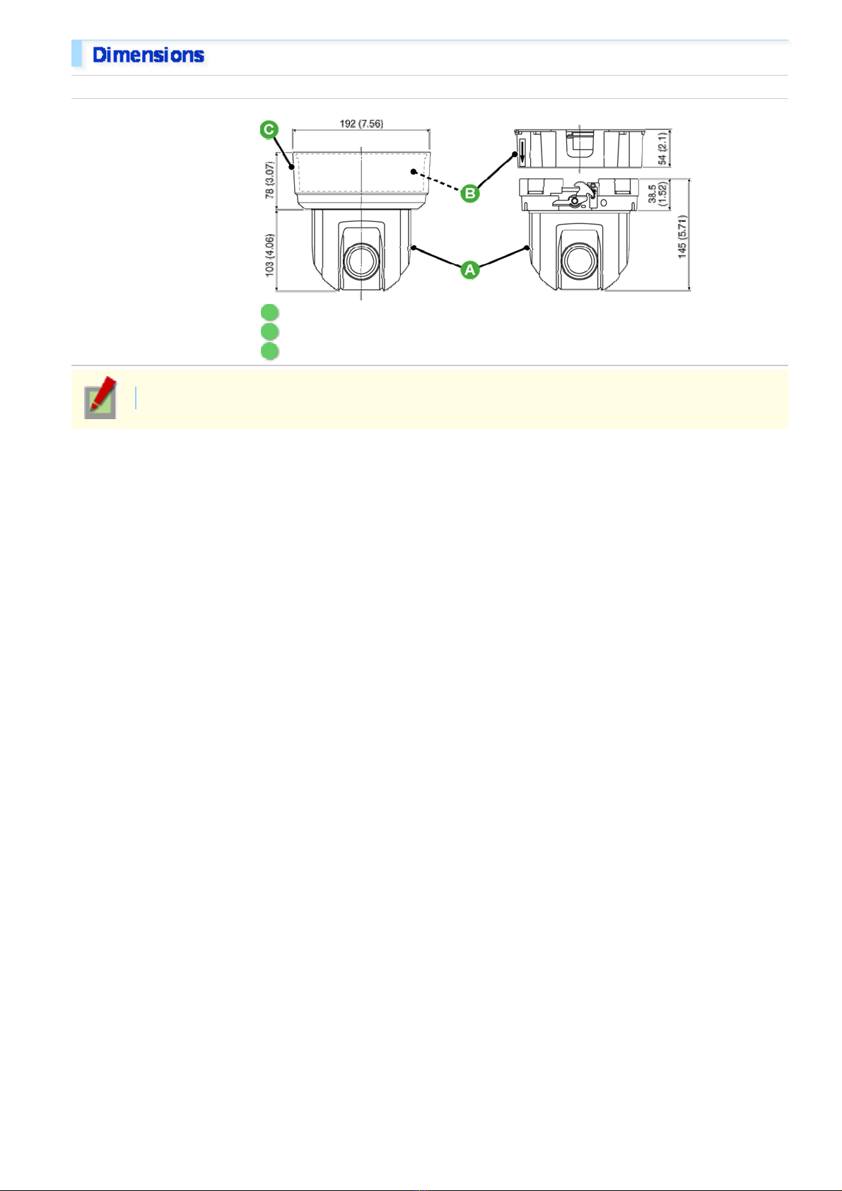
Dimensions
Unit: mm (inch)
A Camera unit: approx. 1.3 kg/45.9 oz.
B Power unit: Approx. 450 g/15.9 oz.
C Surface cover: approx. 110 g/3.9 oz.
Appearance and specifications are subject to change without prior notice or oblig ations.
Introduction5/14
Page 6
This table is displayed using a browser-specific function and therefore not displayed on the PDF
manual.
Refer to the table “Target size and r ecording time” in the electron ic manua l.
This table is displayed using a browser-specific function and therefore not displayed on the PDF
manual.
Refer to the table “Target size and r ecording time” in the electron ic manua l.
Introduction6/14
Page 7
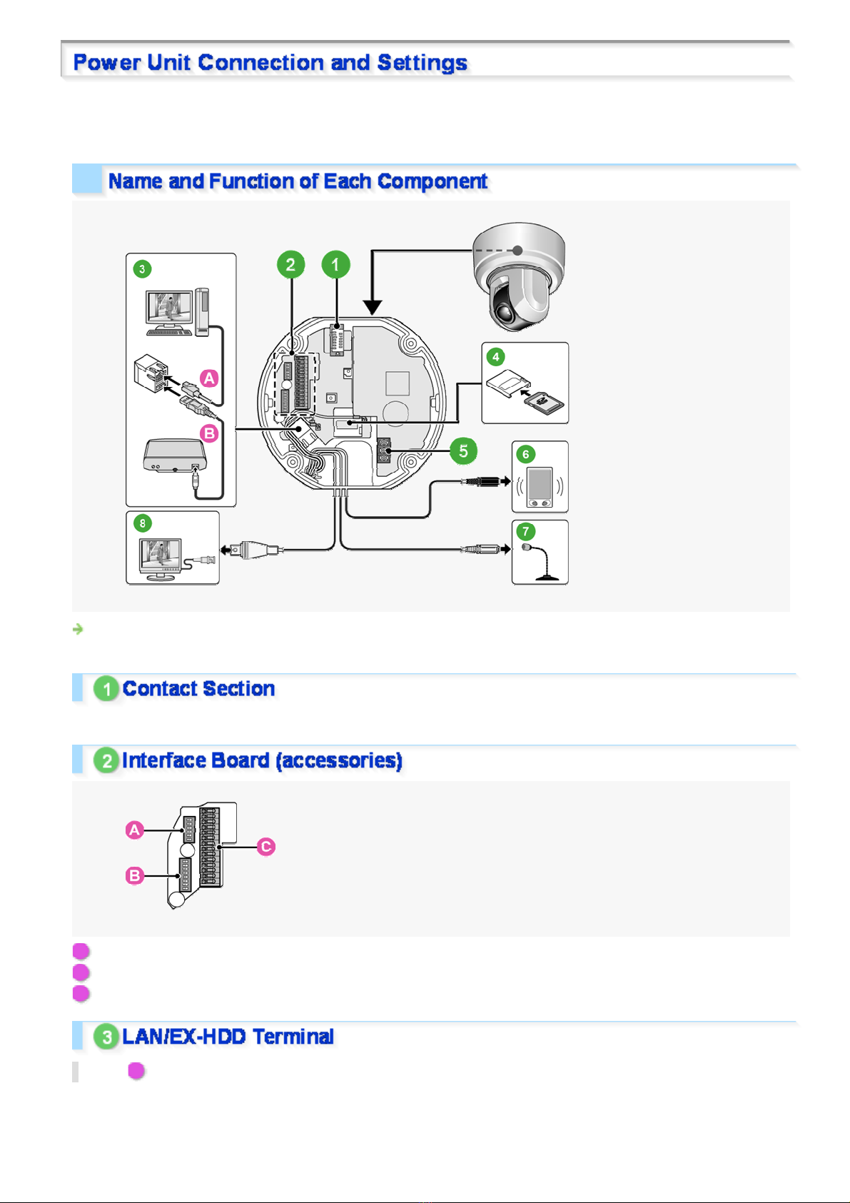
This device is composed of a camera unit, power unit (VA-94S) and surface cover (supplied).
When using this camera, connect and configure the power unit.
For details on terminal conn ec tions, recording media attachment and switch settings, etc., please refer to
“Connection” and “Control/Address Setti ng”.
This is the connection point between the camera unit and the power unit.
A Control switch (transmission rate and protocol setting, etc.)
B Address switch (camera control address setting)
C Control terminal (connection of controller and alarm input/output cable)
Top ( A ): LAN terminal (RJ-45 type)
Use this socket to connect th e camera to your PC to enable net wor k oper ation.
Introduction7/14
Page 8
Bottom ( B ): EX-HDD terminal (USB type)
When recording live video onto an external hard disk, put the hard disk in a dedicated har d dis k case (VAHDC4000, sold separately) and then connect the case to the camera.
When recording live video onto an SD memory card, inser t the card into the slot.
Connect this terminal to the power supply.
There is no power indicato r on the camera.
Connect this jack via an audio cable to the audio input jack of an amplified speaker system or the monitor.
Use this jack to connect an external microphone to listen to the sound while monitoring the live video, or
simultaneously record the video and sound.
Connect this terminal to a monit or , et c. A live video will be displayed on the monitor once the camera is turned on.
By installing an HDMI option board (VA-HDB90, sold separat ely ) , th e camera c an be con nec ted to a
high vision monitor.
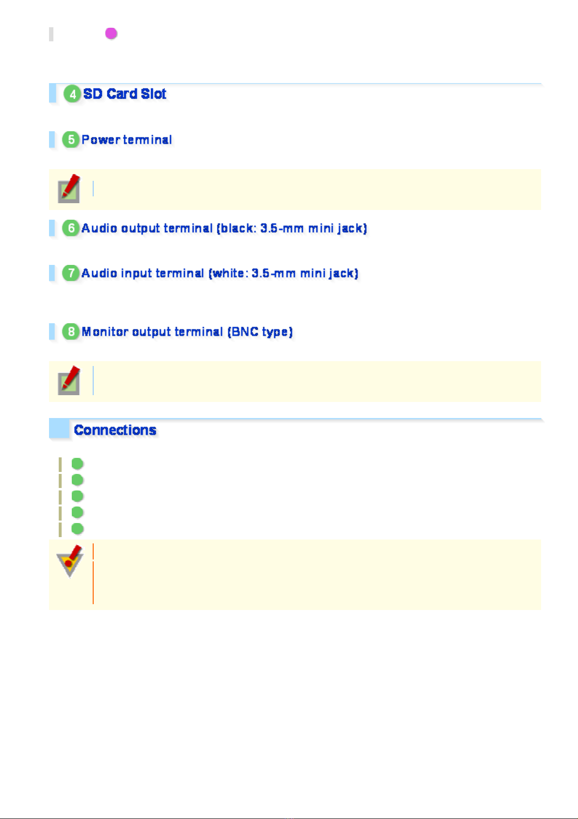
Perform the following connections according to the installation environmen t and application of your camera.
A Power Connection
B Network Connection
C Control Terminal Connections
D Audio Jack Connection
E Installing Recording Media
Before attempting the fo llowing connections, be sur e to turn of f all components of your system.
Improper connection may cause smoke or failures. Before at tempting to connect each system
component, carefully read the instruction manual th at com es with it to familiarize yourself with the
correct connection pr oc edur e.
Introduction8/14
Page 9
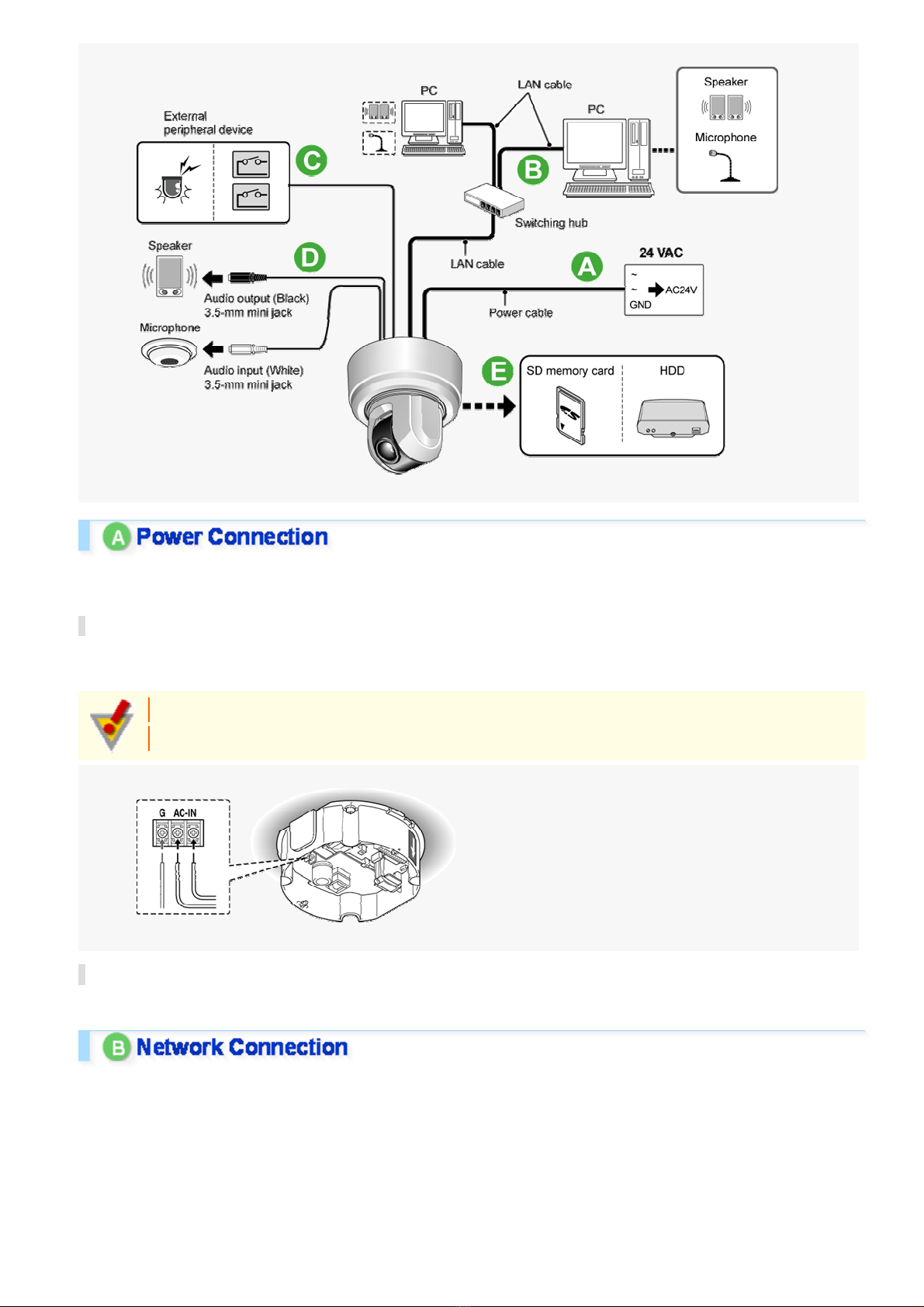
There are two types of power unit, i.e. 24 VAC and 230 VAC. Befor e us ing, always make sure of the purchase d
model number and arrange the wir ing c or r ec tly.
24 VAC Type
Connect the power cable to the power terminal. Although the power terminals have no polarity, the earth
grounding wire must be connec ted to the GND (earth grounding) terminal.
To prevent a fire hazard use any UL listed wir e r ated VW-1.
Be sure to use an 18AWG or thicker wire power cable.
230 VAC Type
Please refer to the instr uc tion manual that came with the product.
This camera is designed so that you can use all of its fun ctions via network operation.
By connecting the network (LAN) socket of the camera to your PC using a LAN cable, you can c onfigure and
operate it from the Web browser installed on y our PC.
Introduction9/14
Page 10
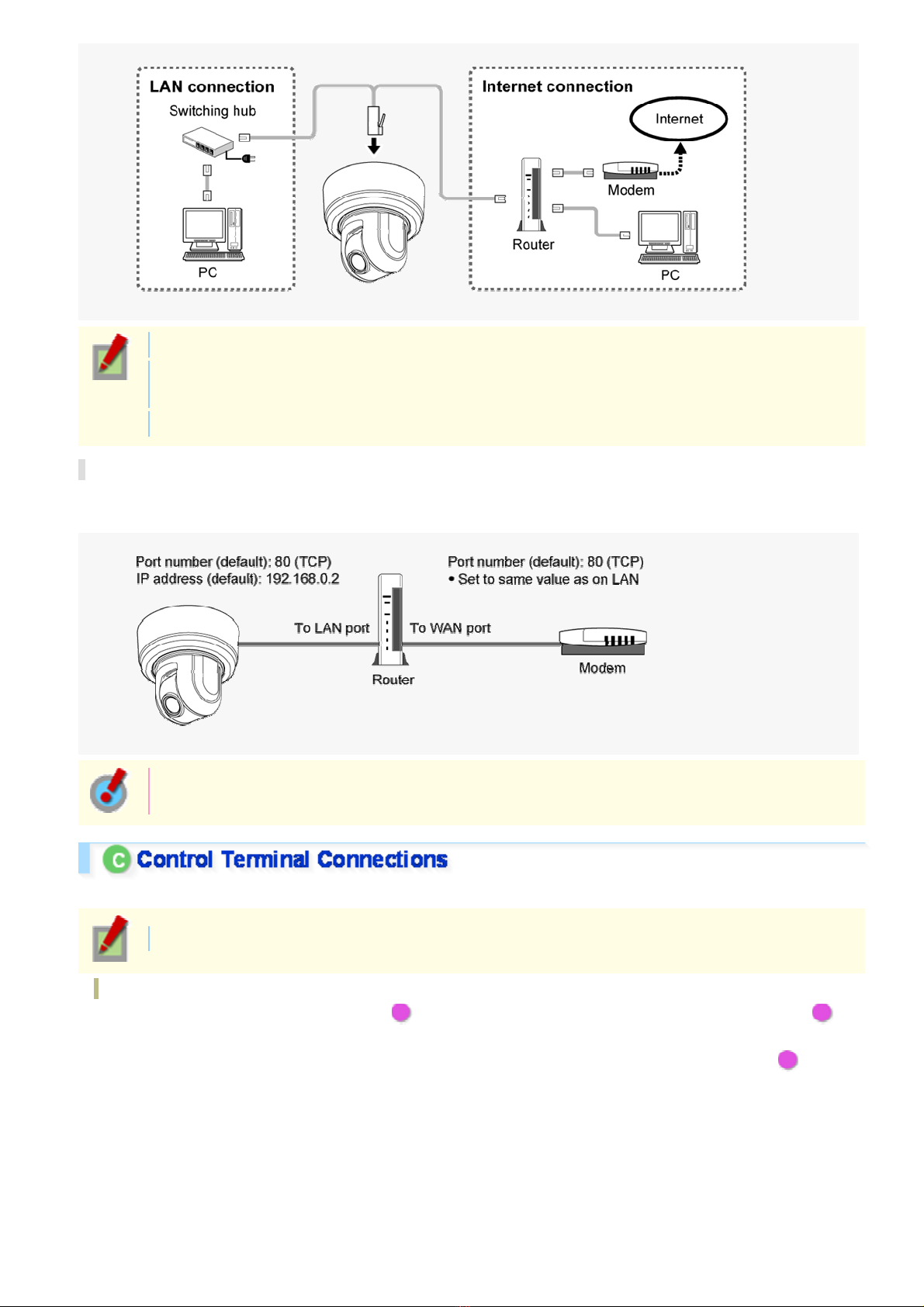
Use a LAN cable no longer than 100 m (109.4 yards) with the shield type CAT5 or higher.
Use a straight-type cable if connecting to LAN, and use a cross-ty pe ca ble if directly connecting the
camera to a PC.
The supported Web browser is Internet Explorer Ver.6.0 SP2 or higher, or Internet Explorer Ver.7.0.
About the internet connection
Port forwarding for the video por t must be enabled on the broadband rout er .
For details on how to set port forwa rd ing, please refer to your router ' s Ins truc tion manual.
To connect two or more cameras, on the NETWOR K SETTINGS s creen, assign them with port
numbers that are different from that of the first camera.
Connect the alarm input/output cable and controller to the control terminal of the interface board.
Use a thicker cable than 24AWG for connection. (Maximum length 600 m)
Installing and removing the interface board
To place the board back, align the hole ( A ) at the right corner of the board to the protruding portion ( B )
and securely fix the board by depr es si ng it.
To connect alarm or other cables to the interf ac e boar d, take out the board by pulling the portion C .
Introduction10/14
Page 11
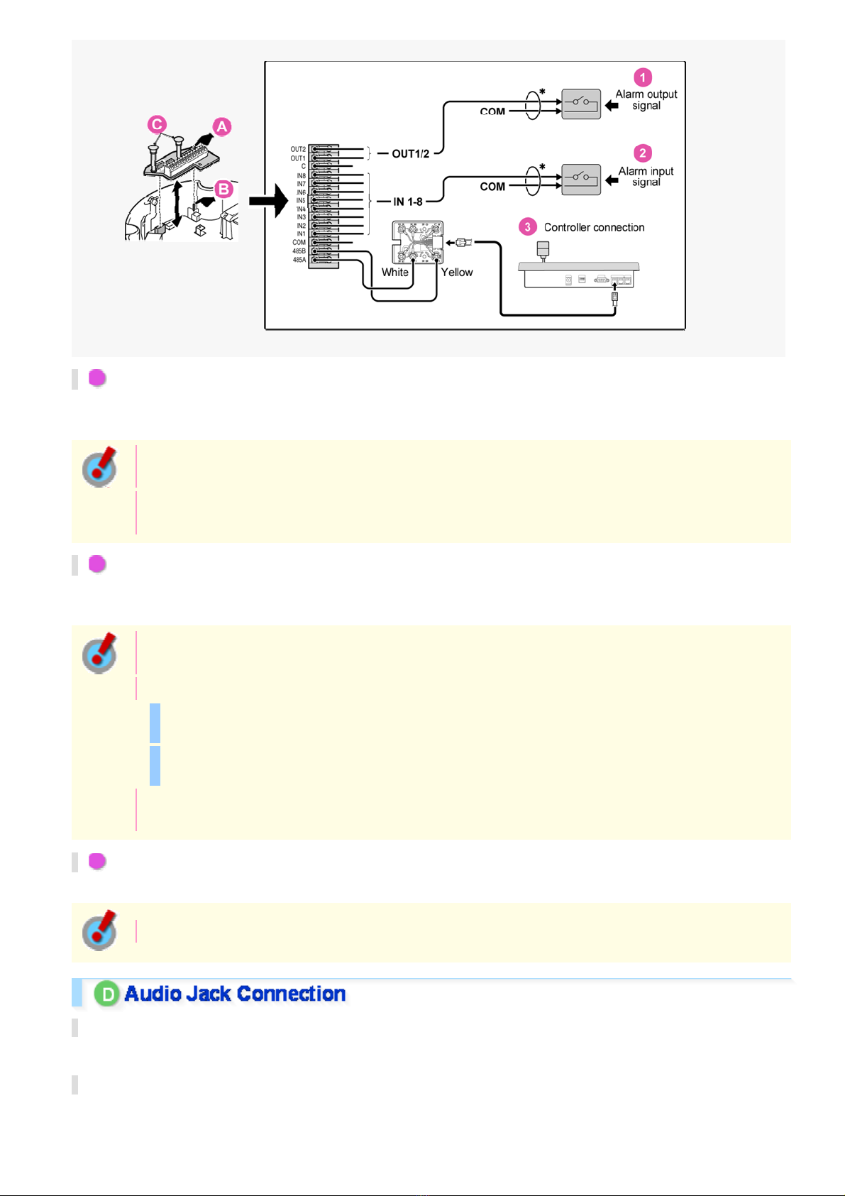
1 Outputting Alarm Signals (OUT 1-2)
Connect a buzzer, lamp, or oth er alar m device to t he alar m output cable.
Alarm can be output via two channels.
After connecting an alar m devi ce , configure the output condit ions for the corresponding alarm outp ut
terminal (ALARM OUT1 or 2) via netwo rk operation on the ALARM SETTINGS screen.
Configuration of alarm output terminal is also possible via remote operation. For that, set [ALARM
OUT] to “REMOTE” on the ALARM SETTINGS screen.
2 Inputting Alarm Signals (IN 1-8)
Connect an alarm switch, infrar ed s ens or , or other device to detect alarm con ditions to the alarm input cable.
Alarm can be input via eight channels .
After connecting an alarm device, configure the input conditions for the corresponding alarm input
terminal (ALARM IN1 or 2) via network oper ation on the ALARM SETTINGS screen.
When using the alarm input terminal for day/night switching, configure the followi ng se tt ings .
Under [DAY/NIGHT], set [DAY/N IGHT] to “COLOR” and select the terminal you want to use in
[EXT ALARM].
On the ALARM SETTINGS screen, in [POLAR IT Y], selec t the signal polarity of the alarm input
terminal.
Connecting an external switch to ALARM IN1 allows you to set the system clock by operating the
switch. To set the system clock, configure the [CLOCK IN] setting on the CLOCK SETTINGS screen.
3 Connecting the Controller (485A/485B)
By connecting a system controller (sold separately), the camera can be controlled remotely.
Configure the protoco l, baud rate and address. (Refer to “Control/Address Settings ” ) .
AUDIO OUT Jack (Black)
Connect this jack via an audio cable to the audio input ja ck of an amplified speaker system or the monitor.
AUDIO IN Jack (White)
Use this jack to connect an external microphone to listen to the soun d while mo nitoring the live video, or
simultaneously record the video and sound.
Introduction11/14
Page 12
This jack supports 3.5-m m dia meter mo naur al m i c r ophone plugs, or monaural line-l ev el input plugs
(the left channel only for stereo plugs).
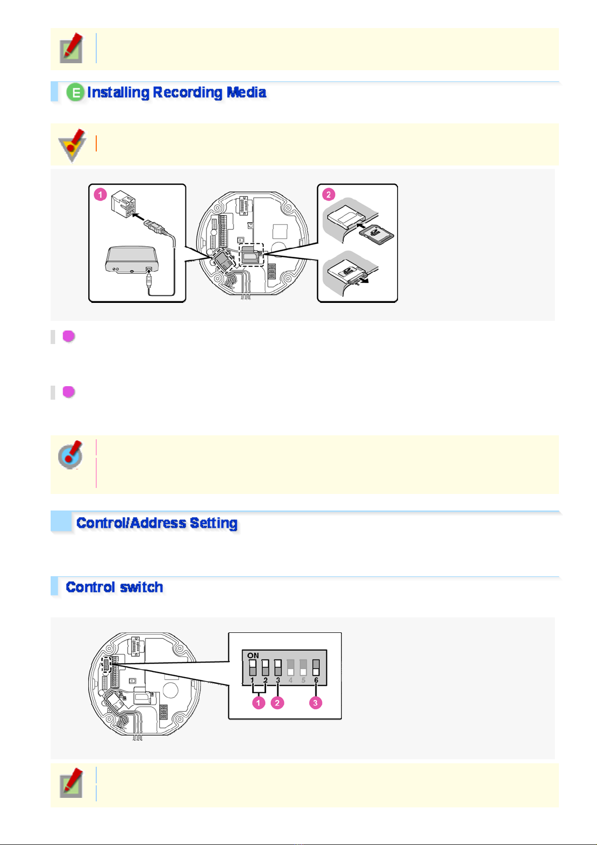
When recording live video on the camera, install an SD memory card or exte rn al har d dis k on the camera.
Always turn the power off when installing a recording medium.
1 Connecting an External Hard Disk
Put the hard disk in a dedicated hard disk c as e (VA-HDC4000, so ld se par ately) and then connect the c as e to the
camera.
2 Inserting an SD Memory Card
Insert the SD card into the slot until it is locked with a clicking sound.
Push the SD card a bit further into the sl ot to ejec t it.
When you insert a new recording medium, format it on the SD/HDD screen.
When you remove the recording medium, first set [SD MEMORY CARD]/[HDD] on the SD/HDD
screen to “NO USE”.
When you connect the camera to a controller, it is necessary to configur e the interface board control switch and
address switch.
This is used to configure tr ans mi ssion rate and protocol, etc.
Switches 4 and 5 are not used.
Settings in bold typefac e i n the ta ble below show the factory default configurations.
Introduction12/14
Page 13
1 Baud Rate
Configure the transmis s ion r ate of connected devices to the tr ans mi ssion rate of the camera.
Transmission Rate Switch 1 Switch 2
2400 OFF OFF
4800 ON OFF
9600 OFF ON
19200 ON ON
When protocol is set to “PELCO”, set to 2400.
2 Protocol
Select the protocol for controlling the camera.
Protocol Switch 3 Corresponding Protocol
SSP (SANYO) OFF Automatic switching between Sanyo SSP and high speed SSP
PELCO ON Automatic switching between PELCO-D and PELCO-P
3 Terminator
When you connect multiple c ame ra s, se t the ter mi nator setting (Switch 6) of the final dev ic e to “ON” and all other
devices to “OFF”.
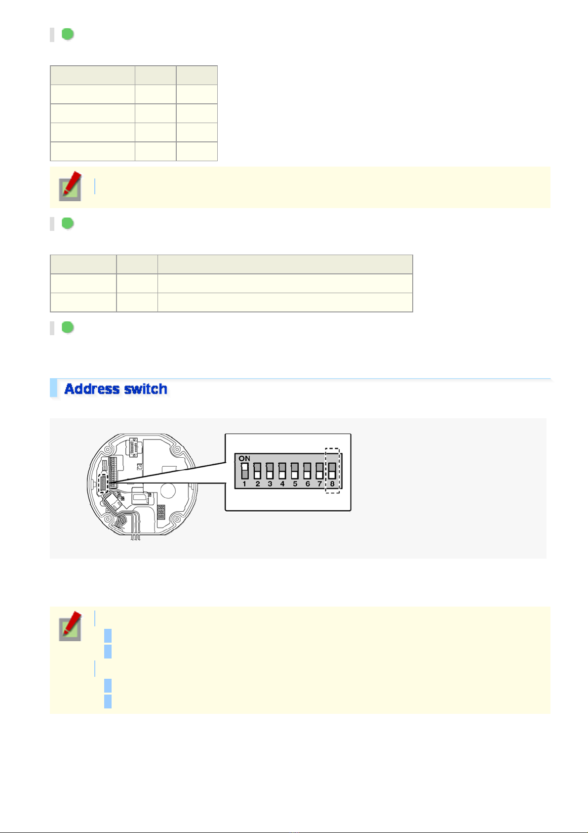
When you connect multiple c ame ra s, allocate a unique RS 485 pr otocol address (camera number ) to each c ame ra .
Configure the address by setting the dip switches to “ON” and “OFF”.
Configure the switche s accor ding to the List of Address Configura tion Switches shown below. Circles in the list
indicate “ON”.
When protocol is “SSP (SANYO)”:
Configurable address es : 1 to 127
Switch 8 is configured to “OFF”.
When protocol is “PELCO”:
Configurable address es : 1 to 255
To configure the address to a number between 128 and 255, set the switch 8 to “ON”.
Introduction13/14
Page 14
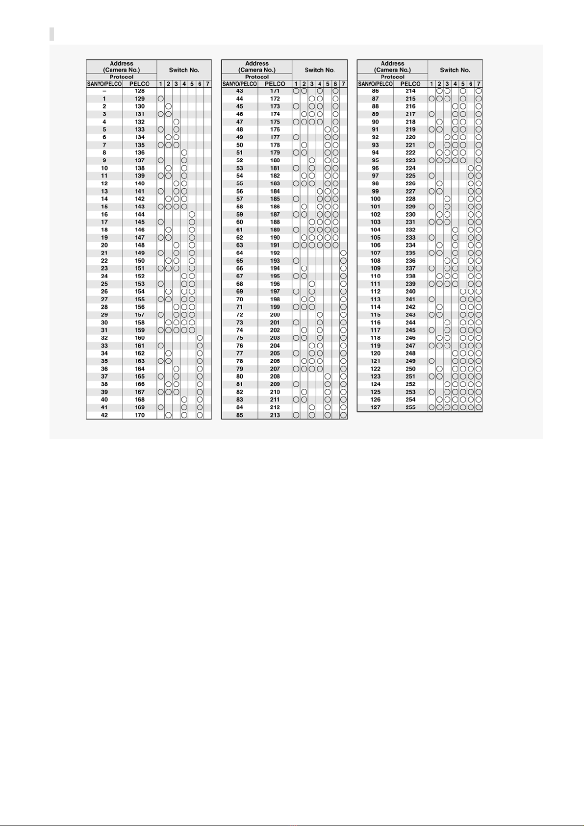
List of Address Configuration Switches
Introduction14/14
Page 15
VCC-HD4600/HD4600P
From Connection to Network Operation
Live V ideo M onit oring
Alarm Detection and Output
Recording Surveillanc e Vid eo
Software Infor mation
Configuration menu quick reference tables
Quick Operation Guide1/14
Page 16
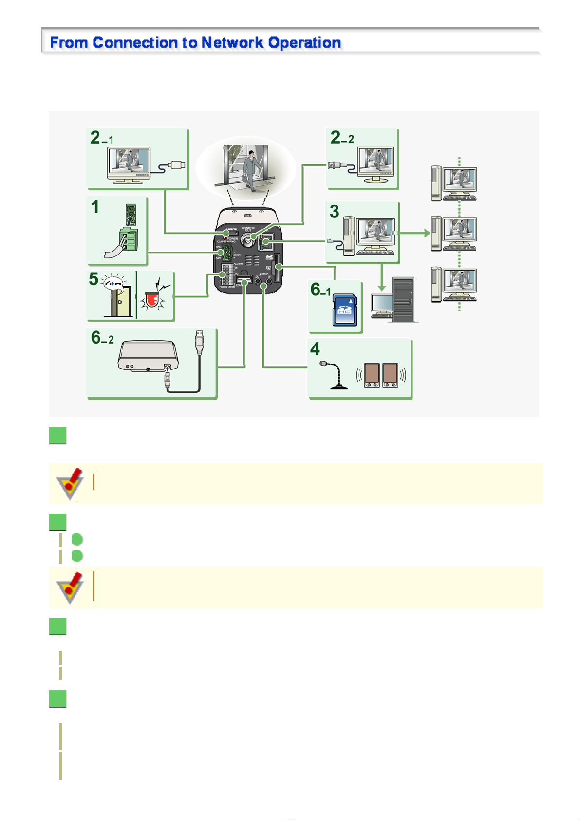
Follow the steps below to set up and connec t th e camera to your PC.
You can use video recording, bidirectional audio communic ations, and other standar d functions of the camera, in
addition to normal live video monit or ing.
1 Connect the power cable to the power terminals.
Use a 24-VAC or 12-VDC power supply.
Do not turn on the camera until you complete all c onnec tions.
2 Connect the monitor to the appropriate terminal.
1 High-definition monitor : HDMI terminal
2 Monitor for video adjustment : MONI TOR OUT terminal
The video cannot be output to the HDMI and MONITOR OUT terminals simultaneously. Set the
preferred output terminal under TV OUT on the VIDEO & AUDIO SETTINGS screen.
3 Connect the network (LAN) socket to your PC using a LAN cable.
Check the operating environment of your PC and perform the follo wing oper ations:
Check the network informat ion on your PC.
Install the “H.264 Plug-in” from the supplied CD-ROM onto your PC.
4 Connect a microphone and a speaker system to the audio input and output jacks of the
camera.
AUDIO IN jack: Use this jack to connect an exter nal microphone to hear the sound with live v ideo, or
simultaneously record the video and sound.
AUDIO OUT jack: Use this jack to connec t an amplified speaker system to send audio mes sa ges from your
PC to the camera.
Quick Operation Guide 2/14
Page 17

5 Connect necessary external devices to the alarm input/output terminals.
ALARM IN1/2 terminal: Connect an external switch, infrared sensor, or other device to detect alarm
conditions such as entry of an intruder.
ALARM OUT 1/2: Connect a buzzer, lamp, or other alarm device to output a signal to warn people of the
occurrence of an alarm condition.
6 Install the recording medium.
After installation, the medium requires to be formatted.
1 SD memory card: Insert it into the SD card slot.
2 External hard disk: Connect the driv e to t he EX-HDD terminal.
7 Turn on the camera.
The power indicator lights up and live video appears on the monitor.
8 Access the camera from your PC's Web browser.
Live video appears on the live s creen. Now, you can perform all network operations from your PC.
Quick Operation Guide 3/14
Page 18
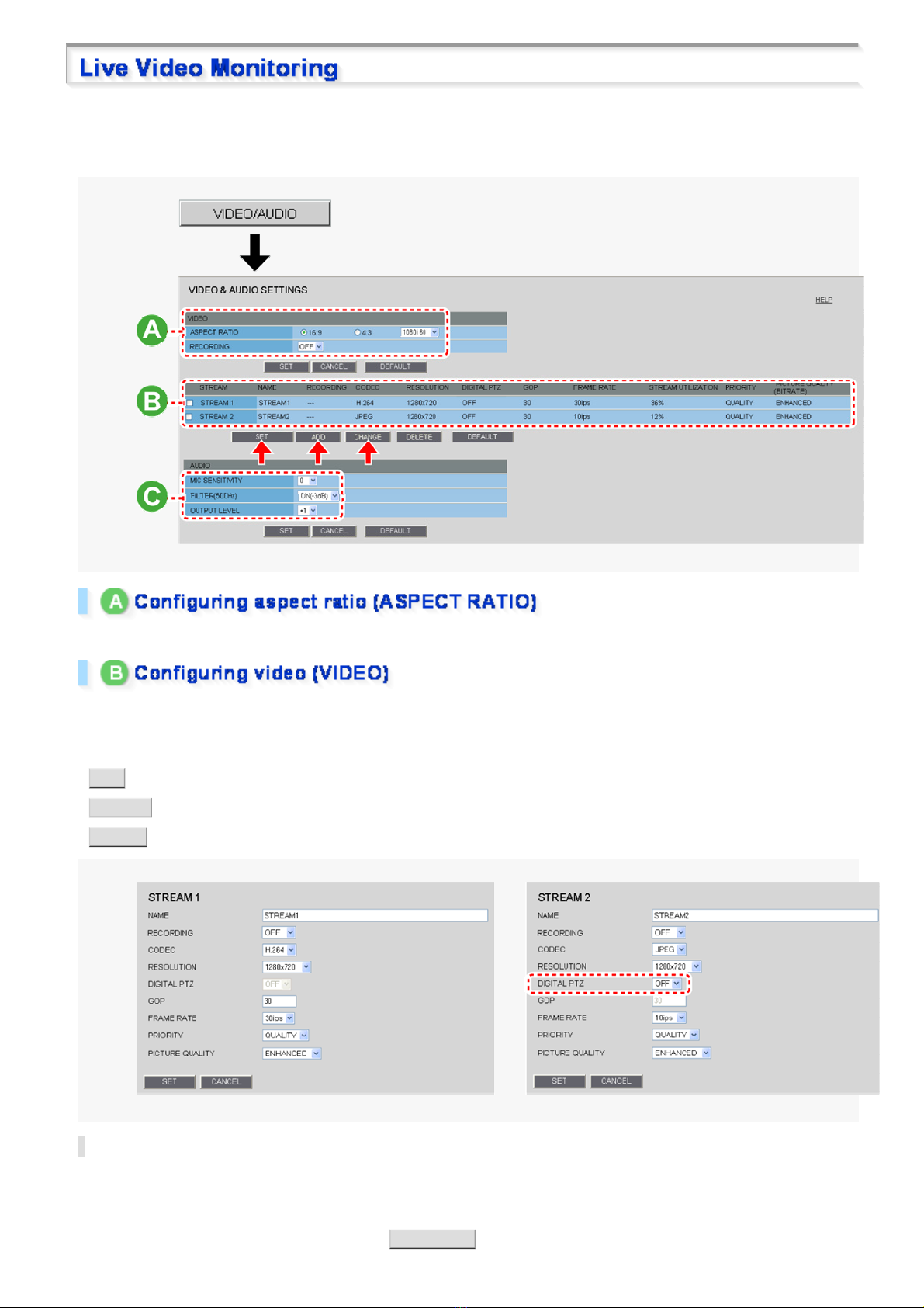
If you are operating the camer a for the first time, check the factor y default video and audio conditi ons on the
VIDEO & AUDIO SETTINGS screen. Change the default settings as desired.
For details, refer to the “VI DE O & AUDIO SETTINGS ” sect ion.
16:9 (Default) → 4:3
By default, the list show s the two stream patterns, STREAM1 and STREAM2. Use the buttons provided below the
list to add, change, or delete str eam patterns.
The factory default settings for STREAM1 and STREAM2 are as shown in the screenshots below.
ADD : Use this button to add up to two custom stream patterns (STREAM3 and STREAM4).
CHANGE : Use this button to change stream settings (STREAM1 to STREAM4).
DELETE : Use this button to delete registered stream patter ns .
Digital PTZ Function
The digital PTZ function lets you clip specific areas of the subject in VGA size and perform zoom, pan, and tilt
operations just as when using a PTZ camera.
To use the digital PTZ function, set [DIGITAL PTZ] to “ON” on the JPEG stream registration screen shown above
(STREAM2 screen in this example) and click DIGITAL PTZ on the liv e screen.
Quick Operation Guide 4/14
Page 19

You cannot select “ON” in [DIGI TAL PTZ] if you se lec ted “H.264” in [CODEC].
Selecting “ON” in [DIGITAL PTZ] fixes the [RESOLUTION] value to a VGA-equi v alent size (“640×
360” in 16:9 aspect ratio or “640×480” in 4:3 aspect ratio).
Audio condition configuration
In [MIC SENSITIVITY], sele ct the mic r ophone s ens itivity.
In [FILTER (500Hz)], enable or disable the audio filter.
In [OUTPUT LEVEL], select the desired audio output level.
Audio output configuration
Set [AUDIO (CAMERA TO PC)] to “ON” on the CLIENT SETTINGS screen.
Audio input configuration
Set [AUDIO (PC TO CAMERA)] to “ON” on the CLIENT SETTINGS screen.
Quick Operation Guide 5/14
Page 20
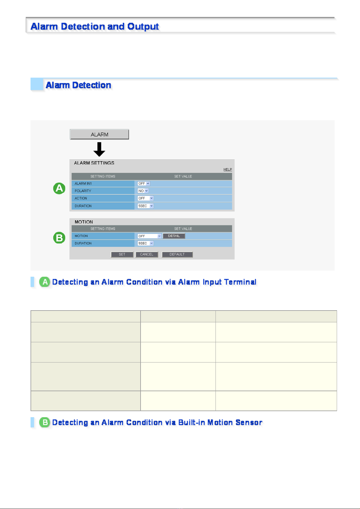
If you are operating the camer a for the first time, check the factor y default alarm detection conditions on the
ALARM SETTINGS screen. Change the default settings as desired.
For details, refer to the “ALARM SET TI NGS” sect ion.
You can configure the camera to detect alarm conditions via the “alarm input terminals” or “built-in motion sensor”.
For how to configure the camera to dete ct alar m conditions via the alarm input term inals , refer to the “Alarm
Input/Output Terminal Connections” section.
Connecting an alarm swit ch , inf r ar ed se ns or , or other ex ternal device to the ALARM IN1/2 terminal enables the
camera to detect alarm conditions such as entry of an intruder.
Setting Item Default Setting Optional Setting
ALARM IN1/2 (Alarm input terminal
number)
POLARITY (Signal polarity)
ACTION (action the camera makes when
an alarm condition is detected)
DURATION (Alarm retention duration)
OFF (Disables alarm
detection.)
NO (Ex.: Detects an alarm
when door is closed)
OFF (No action) ZOOM (Zooms to the specified magnification.)
5SEC (Ex.: Records alarm
video for 5 sec.)
ON (Enables alarm detection.)
NC (Ex.: Detects an alarm when door is
opened.)
CAM1/CAM2 (Switches the monitoring
condition.)
10SEC to 5MIN, CC (Retains the alarm state as
long as the alarm signal persists.)
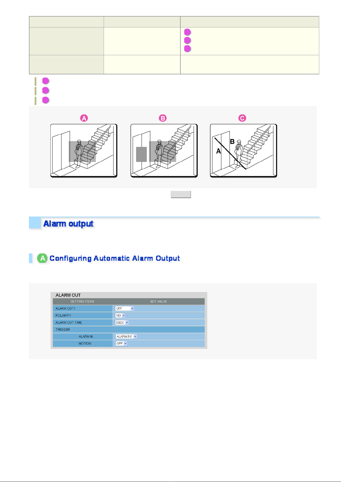
The camera uses the built-in motion sensor to detect alarm conditions.
The motion sensor detects an alarm condition in three ways as follows.
Quick Operation Guide 6/14
Page 21
Setting Item Default Setting Optional Setting
MOTION (Use of built-in
motion sensor)
DURATION (Alarm retention
duration)
A Disabling motion detection in masked areas
B Detecting motion in specific areas
C Detecting motion with lines and ar eas dr awn on the sc re en
OFF (Disables alarm
detection.)
5SEC (Ex.: Records alarm
video for 5 sec.)
A MASKING
B DETECT
C ANALYTICS
10SEC to 5MIN, CC (Retains an alarm state as long as
the motion alarm persists.)
In [MOT IO N] , a fte r se l ecting a mot io n se nsor type, cli ck DETAIL to configure the detection conditions on the
detailed configuration screen.
You can configure the camera to “automatically output alarm signals” or “remotely (manually) output alarm
signals”.
You can configure the camera to auto ma tically output an alarm signal when either of its alarm input termina ls
receives an alarm signal.
Quick Operation Guide 7/14
Page 22
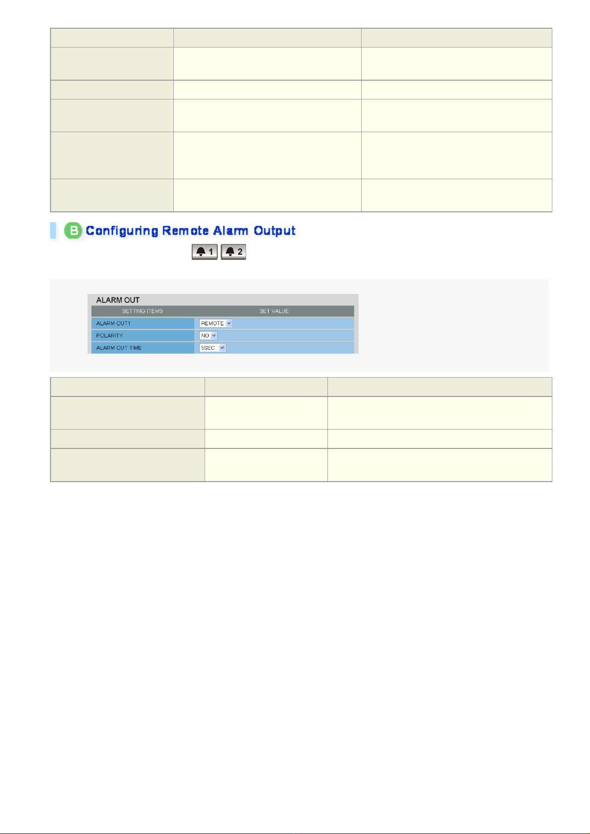
Setting Item Default Setting Optional Setting
ALARM OUT1/ 2 (Alarm
output terminal number)
POLARITY (Signal polarity)
ALARM OUT TIME (Alarm
output time)
ALARM IN (Output
condition)
MOTION (Output condition)
OFF (Disables alarm output.) ON (Enables automatic alarm output.)
NO NC
5SEC (Ex.: Beeps a warning for 5 sec.) 2SEC to 5MIN
ALARM IN1 (Triggers alarm output when
ALARM IN1 terminal receives an alarm
signal.)
OFF (Disables alarm output usi ng m otion
sensor.)
ALARM IN2 (Triggers alarm output when
ALARM IN2 terminal receives an alarm
signal.)
ON (Triggers alarm output usi ng m oti on
sensor.)
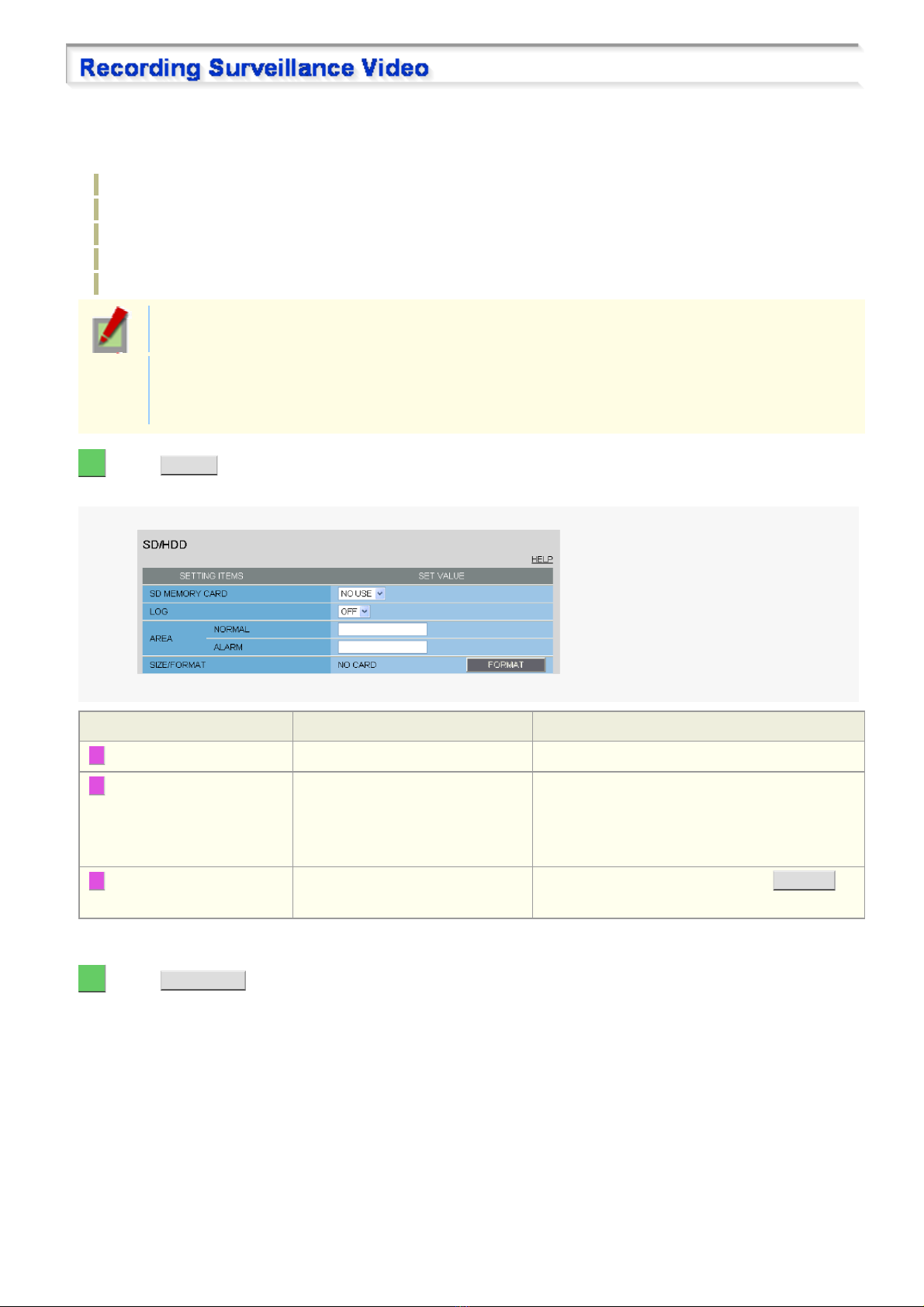
Use the Remote Alarm buttons ( ) provided on the live screen to send alarm signals from the camera's
alarm output terminals .
Setting Item Default Setting Optional Setting
ALARM OUT1/ 2 (Alarm output
terminal number)
POLARITY (Signal polarity)
ALARM OUT TIME (Alarm output
time)
OFF (Disables alarm
output.)
NO NC
5SEC (Ex.: Beeps a warning
for 5 sec.)
REMOTE (Enables remote alarm output.)
2SEC to 5MIN, CC (Stops alarm output when Remote
Alarm button is clicked.)
Quick Operation Guide 8/14
Page 23
Before recording video, install a recording medium (SD memory card or external hard disk) on the camera and
perform the following proc edures.
You can record the following videos or information on the media.
Normal recording
Alarm video recording
Backup video recording in ev ent of a network failure
Manual video recordi ng triggered by the emergency recording button
Access and system logs
In cases where both an SD memory card and an external har d dis k dr iv e ar e simultaneously
connected, the hard disk drive takes precedence.
The recorded video cannot be played back on the camera. To play back the recorded video, use the
supplied downloader software (HDC Downloader) and playback software (DLViewer) to play back the
video on the PC.
1 Click SD/HDD in the configuration menu.
On the SD/HDD screen, you can format the rec or ding m edia.
Setting Item Default Setting Required Setting/Operation
1 SD MEMORY CARD/HDD NO USE USE (Use the media for recording)
2 AREA (Ratio of the
recording areas)
3 SIZE/FORMAT Displays the recording capacity of
NORMAL: 80 (Normal recording
storage area)
ALARM: 20 (Alarm/backup
recording storage area)
the media.
Change the rate between the “NOR M AL” and
“ALARM” areas as needed.
Check the storage capacity and click FO RMAT .
When finished forma tti ng the SD memory card , clos e the SD MEMORY CAR D scre en.
2 Click RECORDING in the configuration menu.
On the RECORDING screen, configure the recording settings as follows .
Quick Operation Guide 9/14
Page 24
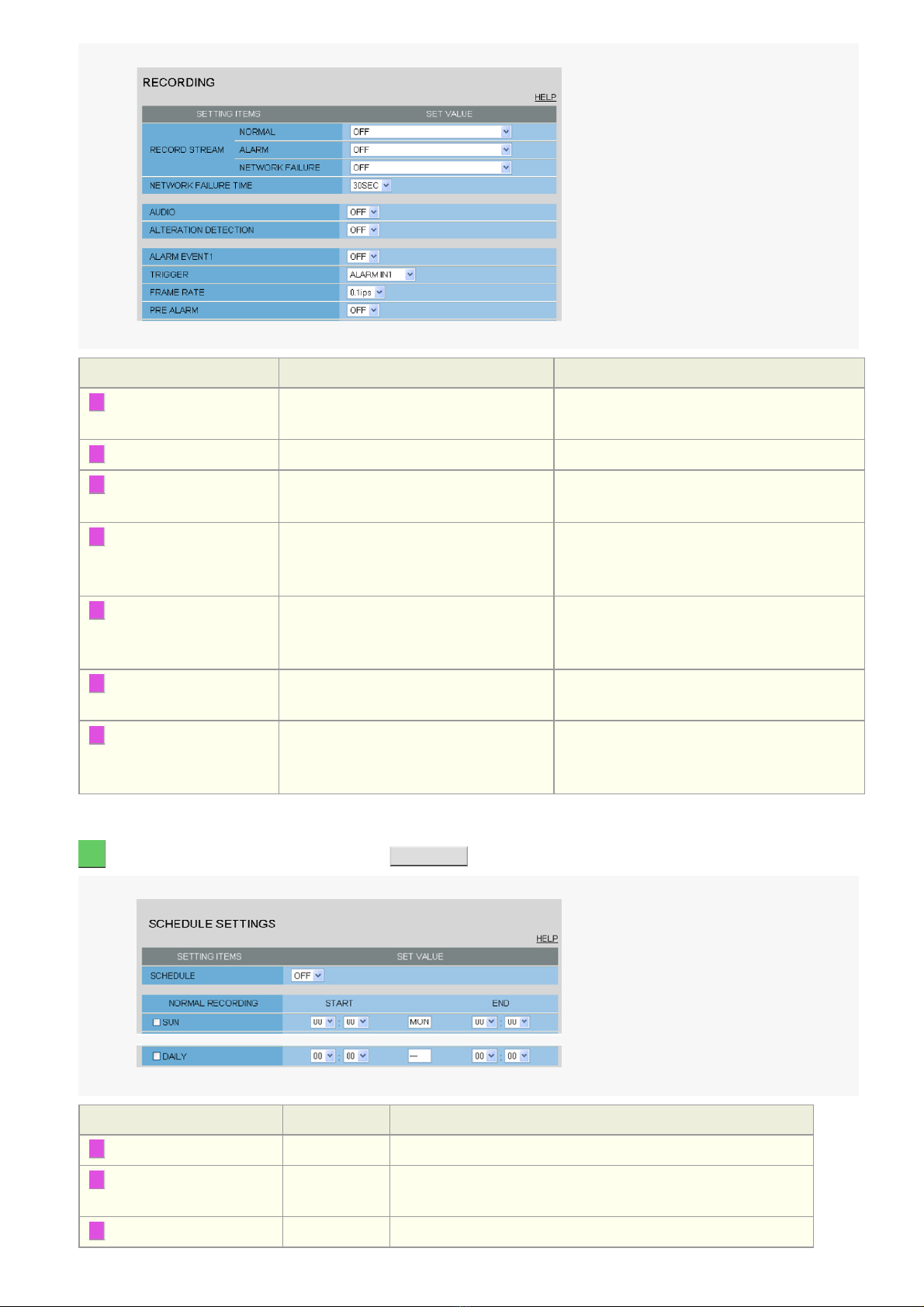
Setting Item Default Setting Required Setting
1 RECORD STREAM OFF Select the desired stream (STREAM1 to
STREAM4).
2 AUDIO OFF ON (Records video and sound simultaneousl y)
3 ALTERATION
OFF ON (Detects tampered images)
DETECTION
4 ALARM EVENT1 OFF ON
You can configure three patterns of recording
conditions (for ALARM EVENT1 to 3).
5 TRIGGER (Recording
trigger conditions)
ALARM IN1 (Triggers recording when
ALARM IN1 terminal receives an alarm
ALARM IN2, MOTION, ALARM OUT1/2,
NETWORK FAILURE
signal.)
6 PRE ALARM OFF ON (Records video for a specific period before
alarm occurrence. )
7 REC BUTTON OFF ON (Records video using the emergency
recording button on the live screen control
panel)
When finished confi gur ing the above basic recording sett ings , configure the recording s ch edule as r equir ed.
3 On the RECORDING screen, click SCHEDULE .
Setting Item Default Setting Required Setting
1 SCHEDULE OFF ON (Enables recording schedule configuration.)
2 SUN to SAT (START/END) 00:00/00:00 Configure the start/end time of recording for each day of the week.
(Ex.: 08:0 0/20:00)
3 DAILY 00:00/00:00 Select this check box to set the same start/end time for every day.
Quick Operation Guide 10/14
Page 25

When finished confi gur ing the schedule settings, the sch edule map appears.
Recording video to your PC
By using the recorder/player application VA-SW3050 Server/Client (optional), you can record and play back
streaming video dat a from the camera on your PC.
To make the maximum use of this camera, we reco mmend t hat you us e this application.
You can record JPEG images only.
You need to configure recording and other conditions on the applic ation's configurat ion s c r eens .
Recording video to an FTP server
To record video by sending image dat a from the cam er a to an FTP server, you need to configure the image
transmission conditions on the FTP SETTINGS screen.
You can record JPEG images only.
Quick Operation Guide 11/14
Page 26
You can install the following softwar e on you r PC to extend the capabilities of your surveillance system .
The CD-ROM that comes with the camera includes all the supplied software.
A H.264 Plug-in (Plug-in for monitoring live video as high-quality moving images)
This plug-in software is required to display H.264 video on the live screen. Be sure to install it on each computer
from which you access the camera via network operation.
B HDC Downloader (Application for downloading the video recorded on the camera's
recording media (SD memory card/external hard disk) to the PC)
You can download JPEG image and H.264 video data.
The application lets you searc h for the video/image data to download by date and time or by alar m event.
It is also possible to connect a recording medium to your PC to directly copy video/image data.
C DLViewer (Application for playing back downloaded alarm video, etc.)
You can play back JPEG image and H.264 video data.
The application also offers the capability to save and print video/image data.
D VA-SW3050Lite (Application for monitoring live video from more than one camera)
This monitoring application is designed for use with SANYO network cameras.
You can access up to 128 cameras simultaneously.
The application lets you monitor video images from connecte d cameras in either the single screen or the 4-
screen, 9- screen, or 16-split s c r een m ode.
E Auto IP Setup (Utility for automatically setting up IP addresses when two or more new
cameras are connected)
This utility automatically assigns a unique IP address to each camera that has the factory default IP address
(“192.168.0.2”).
Using the utility's camera search function, you can che ck th e IP addr es se s of al l cameras ex is ting on the
same local network.
It is also possible to check and correct overlapping IP addresses.
VA-SW3050Server/Client (Application for recording and playing back streaming images from
camera)
This recorder/pla ye r appl ic ation is designed for use with SANYO network camer as .
This is a complete version of the VA-SW3 050 se r ies sof tware, which offers all the functions you need to
perform monitoring, recording, search, playback, and other operations in a surveillance system.
This software requir es at least two PCs that serve as the server and the client.
Quick Operation Guide 12/14
Page 27
Click MEN U on the control panel to display the administrator co nfiguration menu that includes a se ri es of menu
selection buttons .
If you are a surveillance system administrator, use t h ese buttons to conf igure necessary settings according to the
installation environment and application of your camera.
Configuration Related to Network Connection
Operation Configuration Screen (Menu)
Changing the camera's IP address. NETWORK SETTINGS
Using SANYO's DDNS service.
Using SSL communicati on.
Streaming H.264 video in multicast
Clock and Camera Title Configuration
Operation Configuration Screen (Menu)
Adjusting clock to specific time based on external input signal CLOCK SETTINGS
Configuring the camera ti tle
Configuration Related to Access and Security
Operation Configuration Screen (Menu)
Registering new users USER REGISTRATION
Changing the password, user name, and operation privilege of
users
Allowing all users to access the camera without any authentication
check
Restricting PCs that have access to the camera SECURITY SETTINGS
Configuration Related to Live Video
Operation Configuration Screen (Menu)
Accessing the camer a from video viewer or similar software to view
live video
Hiding specific portions of video CAMERA SETTINGS (PRIVACY MASK)
NETWORK SETTINGS
Alarm-Related Configuration
Operation Configuration Screen (Menu)
Sending an alarm image via e-mail E-MAIL SETTINGS
Using the alarm input terminals to switch the camera between the
color and black-and-white video modes
CAMERA SETTINGS (DAY/NIGHT)
Recording-Related Configuration
Operation Configuration Screen (Menu)
Recording video with the camera for backup in the event of a
network failure
Recording images from the camera to an FTP server FTP SETTINGS
RECORDING
Quick Operation Guide 13/14
Page 28

Optional Configuration
Operation Configuration Screen (Menu)
Updating the camera's firmwar e to the lat est version. OPTION SETTINGS (FIRMWARE UPDATE)
Restoring the factory default settings OPTION SETTINGS (FACTORY DEFAULT)
Backing up or uploading settings OPTION SETTINGS (MENU BACKUP/MENU
UPLOAD)
Viewing the access log, system log, and operation log OPTION SETTINGS (LOG)
Quick Operation Guide 14/14
Page 29
VCC-HD5600/HD5600P series
Access the camera from your Web browser.
Live Screen Components
Control panel
Tool panel
Information bar
Working with Live Screen1/18
Page 30
1 Start Internet Explorer.
The supported Web browser is Internet Explorer Ver.6.0 SP2 or higher, or Internet Explorer Ver.7.0.
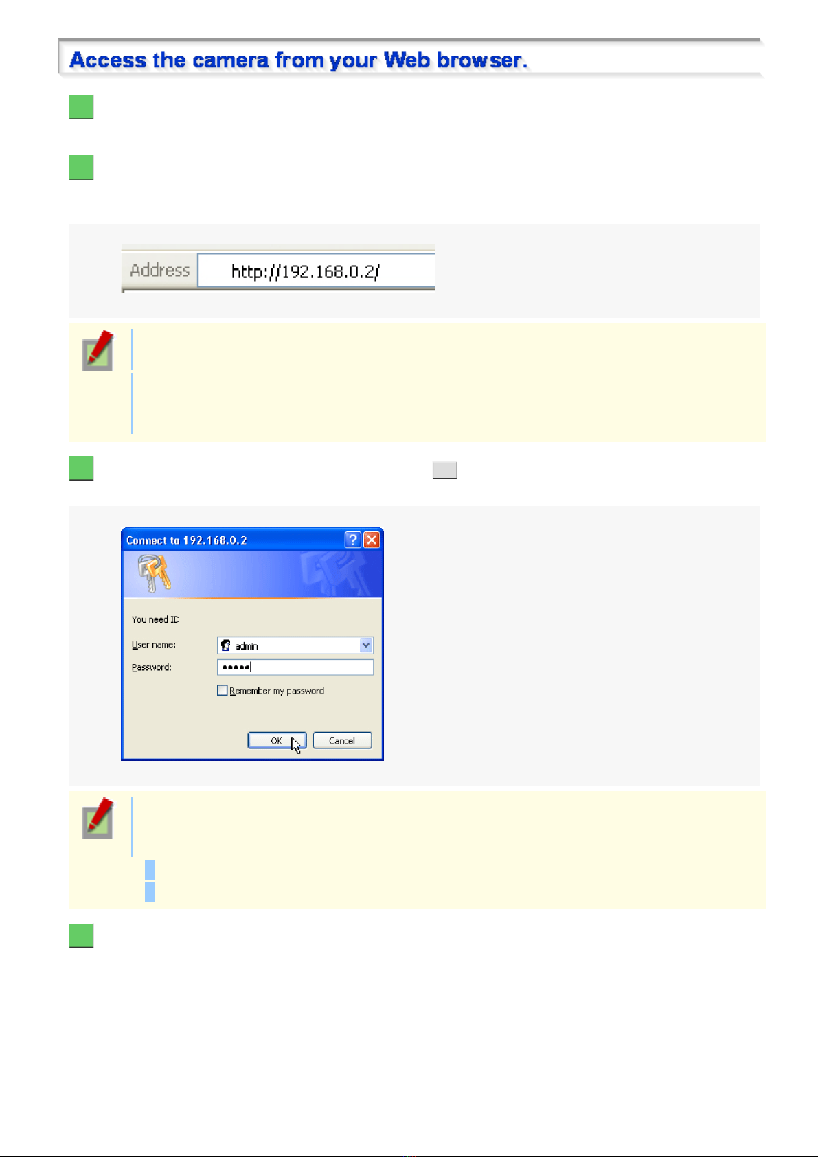
2 In the address bar, type the IP address of the camera and press [Enter] key.
When you access the camera, the login screen appears.
If this is the first access to the camer a, in t he Add re ss bar, enter the default IP address as follows.
If [SSL] on the NETWORK SETTINGS screen is set to “ON”, input “https://” before ent er ing the IP
address.
Attempts to access the camera using the default IP address will fai l if t hat address is already being
used by another device in the network.
If so, change the IP address of the existing device before accessing the camera.
3 Type your user name and password and click OK .
The language selection screen appears.
When you access the camera for the fir s t time, login as an admin user and perform the necessary
configurations.
User name and password default values are as follows:
User name: admin
Password: admin
4 Click the button corresponding to the language you want to use.
The live screen appears.
From the second login onwards, the live screen appears automatic ally by skipping the language selection screen.
Working with Live Screen2/18
Page 31

<Available lang uages >
English, French, Germ an, Spanish, Japanese
You can display the language selection screen by using the LANGUAGE button on the live screen
control panel.
If this is the first access to the camera, configure the system clock on the CLOCK SETTINGS screen.
You can access only one camera at a time from your Web browser.
To access two or more cameras from your PC simultaneously, use the following software.
Monitoring software “VA-SW3050Lite” (Supplied)
Installing this software adds to your PC the capability to simu ltaneously access two or more cameras and
monitor live video from all c onnec ted cameras on a multi-view screen.
Recording software “VA-SW3050Server/Client” (Optional)
This software is higher-grade s oft war e than “VA-SW3050Lite” that adds recording and playbac k capa bilities
to your PC, in addition to video image monitor ing.
This software requires at least two PCs that serve as the server and the client, respectively.
Working with Live Screen3/18
Page 32

When you access and log into the camera successfully, the live screen appears.
For details, refer to the linked information.
Video display area ( A )
Control Panel ( B )
Tool Panel ( C )
Information Bar ( D )
1 Current date and time
Shows the current date and time based on the clock settings configured on the CLOCK SETTINGS screen.
You may change the date-time fo rmat (mont h/day/year, year/month/day, or day/month/ ye ar), clock
type, character size, and display position on the CLOCK SETTINGS screen.
2 Zoom magnification
The current zoom magnification is dis play ed.
3 Video/image display
Shows JPEG images or H.264 video.
To change the video/image stream displayed on the live screen, click CLIENT SETTINGS on the control panel
and, on the CLIENT SETTINGS screen , selec t the desired stream.
Working with Live Screen4/18
Page 33

Image centering operation
Clicking the video image changes the camera’s orientation so that the point where you click is
located at the center of the image.
Working with Live Screen5/18
Page 34

Click buttons according to your operation purpose.
For details, refer to the linked inform ation.
A PTZ operation section: You can use the controls on this section to perform operations such as
pan, tilt, zoom and move to preset positions, etc.
B CLIEN T SETTINGS : Click this to select the live stream and streaming protocol for each user.
C MEN U : Click this to display the configuration menu.
D LANGUAGE : Click this to display the language selection screen.
E DISPLAY : Click this to display the image size adjustment panel.
Required operation priv ilege: admin, operator 1, operator2
Working with Live Screen6/18
Page 35

You can change zoom magnificat ion by operating the slide bar and buttons.
(WIDE):
(TELE):
Zooming continues if th e butt on is kep t depressed.
Click the buttons to adjust the f oc us .
(NEAR):
(FAR):
(AUTO FOCUS):
The camera lens orientat ion c an be ch anged by dr agging or c lic k ing the mouse on the screen.
Drag operation
Operate as though using a joy stick for pan/tilt operation on the system controller.
Drag the central cursor hori z ontally to pan and vertically to tilt.
Continuous pan/tilt oper ation can be performed in line with the cursor move men t.
Zooms out.
Zooms in.
In case electronic zoom is enabl ed, you can activate the electroni c zoom by clicking the
after the maximum optical zoom magnification (10x) is exceeded.
Electronic zoom magnif ic ation: 2x, 4x, 8x, 16x
Focus on a near object
Focus on a distant object
Automatic focus
button
Working with Live Screen7/18
Page 36

The pan/tilt speed acceler ates as the cursor moves further from the center.
Click Operation
The camera orientation c hanges according to the movement of cursor that is made by cl ic k ing on the screen.
Right-click the screen to return the camera lens orient ation to its original position.
Click a button to start the corres ponding auto mode operation (the button lights).
(Sequence):
(Auto
pan):
(Tour):
The camera moves between multiple preset positions that were configured on the AUTO
MODE SETTINGS screen at regular intervals.
The camera reciprocat es between the two positions configures on the AUTO MODE
SETTINGS scree n .
A registered operating pattern, for example pan-tilt-zoom, is repeated.
Configure each operating pattern on the AUTO MODE SETTINGS screen.
The operation corresponding to the pattern number currently selected on the AUTO MODE
SETTINGS screen is conducted.
PRESET MEMORY
Select the registration number (1 to 255) from the pull-down menu and click MEMO RY .
The current camera lens orientation, zoom magnification and focus are registered.
The preset position can also be registered in the PRESET POSITION SETTI NGS scr een.
PRESET POSITION
Specify the preset posit ion registration number and cl ic k GO .
The camera lens orientation, zoom magnification and fo cu s wil l be reg is tered.
Registration number How to specify
1 – 8
9 to 255
Click the number button on the panel ( 1 to 8 ).
Select from the pull-down menu.
Specify the number (1 to 16) from the pull-down menu and configure ON/OFF.
Click CLIENT SETTINGS on the control panel to display the CLIENT SETTINGS scr een.
On this screen, you can perform the following operations:
A Configuring the video stream displayed on the live screen
B Configuring the audio
C Changing your password
Some administrator configuration screen settings may limit the operation s you can per form on this
screen.
Working with Live Screen8/18
Page 37

Shows the name of the user currently accessing the camera.
Select the stream you want to dis play on the live s c r een.
STREAM1, STREAM2, STREAM3, STREAM4
The pull-down menu shows a list of permitted streams that are configured in [LIVE STREAM] on the
USER REGISTRATION screen (administrator configuration screen).
This item will not be shown if [ACCESS LEVEL] is set to “admin” on the USER REGISTRATION
screen.
You need to configure in advance the vi deo c onditions for each stream on the VIDEO & AUDIO
SETTINGS screen (adminis trator configuration s creen).
Select the H.264 video streaming method (protocol).
UDP UNICAST (LOCAL AREA)
RTSP (LOCAL AREA RECORDING)
HTTP (INTERNET)
MULTICAST
Click SET to save the settings. To close the screen without saving the settings, click CLOSE .
This camera supports bidirectional audio communications, so you can send and receive audio between the
camera and your PC.
Hearing sounds from camera
Sending audio messages to camera
To perform bidirectional audio communications, for both the camera and your PC, you must connect
a microphone to the audio input jack and a speaker system to the audio out put jack.
To hear the sounds from the camera, your PC need s a sound c ar d ins talled.
You need to configure in advance the audio settings on the VIDEO & AUDIO SETTINGS screen
(administrator configuration screen).
1 Click CLIENT SETTINGS on the control panel.
The CLIENT SETTINGS screen appears.
Working with Live Screen9/18
Page 38

2 In [AUDIO (CAMERA TO PC)], select “ON”, select the [DEFAULT ON] check box, and click
SET .
This causes the client PC to start up with the audio output capability enabled when connected to the camera, so
that the user can hear sounds from the cam er a.
Setting to “OFF” causes the Receive Audio button and the volume control to disappear from the tool
panel.
3 Use the tool panel controls.
1 Receive Audio button
: Reception of audio enabled
: Reception of audio disabled
2 Volume control
Use this slider knob to control t he audio output volume.
From your PC, you can send audio alerts to sus pic ious people or communicate with people at the camera.
Required operation priv ilege: admin, operator 1, operator2
Only a single user per camera may send audio messages at a time. If two or more users send audio
simultaneously, the user who sends last will take precedenc e.
1 Click CLIENT SETTINGS on the control panel.
The CLIENT SETTINGS screen appears.
2 Set [AUDIO (PC TO CAMERA)] to “ON”, select the [DEFAULT ON] check box, and click
SET .
This sets the client PC to always enable the audio transmission capab ility when connected to the camera so that
the user can send audio messages to t he camera.
Setting [AUDIO (PC TO CAMERA)] to “OFF” causes the Send Audio button to disappear from the
tool panel.
Working with Live Screen10/18
Page 39

3 Click the Send Audio button on the tool panel to send audio messages to the camera.
: Sending of audio enabled
: Sending of audio disabl ed
You can change your own password.
1 In the [PASSWORD CHANGE] field, type a new password.
You can type 4 to 32 alphanumeric characters.
2 In the [CONFIRM PASSWORD] field, type the same password again for confirmation and
click SET .
These items will not be shown if [PASSWORD SET] is se t to “admin” on the USER REGISTRATION
screen.
Update your password periodically for security reasons.
Click MEN U on the control panel to display the configu ra tion menu that includes a series of menu selection
buttons.
Clicking one of these menu selection buttons displays the corresponding configuration screen.
If you are a surveillance system administrator, use these buttons to configure necessary settings according to the
installation environment and application of your camera.
Required operation priv ilege: admin, operator 1 (“admin” only for NETWORK SETTINGS screen)
Without the required operation privilege, you will be presented with an authenticati on che ck dialog
box when you click MENU on the live screen. In this case, you cannot access the menu se lec tion
buttons until you enter an adequate user name and password.
Working with Live Screen11/18
Page 40

Menu Selection Buttons
Button Configuration Screen (Menu) Operation
NETWORK NETWORK SETTINGS Config ure the network settings of the camer a.
1
CLOCK CLOCK SETTINGS Configure the clock date/time, daylight saving m ode, automatic
2
USER USER REGISTRATION Register new login users, or change or delete existing user
3
VIDEO/AUDIO VIDEO & AUDIO SETTINGS Configure the video and audio conditions.
4
CAMERA CAMERA SETTINGS Configure the monitori ng conditions and other settings
5
PAN/TILT PAN/TILT Configure the pan/ti lt conditions.
6
ALARM ALARM SETTINGS Configure the alarm input/output settings and the motion sensor
7
RECORDING RECORDING Configure the recording conditions of the camera.
8
SD/HDD SD/HDD Format the SD memory card or external hard dis k.
9
E-MAIL E-MAIL SETTINGS Configure the alarm notifi cation e-mail function and other
10
clock adjustment , and other settings.
data.
according to the installation environment of the camera.
function.
automatic trans mission settings.
FTP FTP SETTINGS Configure the image streaming conditio ns if you int end to
11
SECURITY SECURITY SETTINGS Configure the security settings for permitting or reje cting the
12
SCHEDULE SCHEDULE SETTINGS Configure the time period during which recording with the
13
OPTION OPTION SETTINGS Perform op erations such as updating the firm ware, restoring the
14
record images from the camer a to an FTP serv er.
access to the camera from up to 10 PCs.
camera is activated.
factory defaults, and backing up and uploading settings.
Other Buttons
Operation Buttons Function
HELP Provides an explanation of each function.
1
2
LIVE Closes the configuration screen and returns to the live screen.
Click LANGUAGE on the control panel to display the language selection screen.
English, French, Germ an, Spanish, Japanese
Working with Live Screen12/18
Page 41

When the language selection screen appears, select the desired language within 10 seconds.
Otherwise, you will be brought back to the live screen with the previous language setting.
Click DISPLAY on the control panel to display the image siz e adjus tment panel.
: Panel is minimized. Clicking the button opens the panel.
: Clicking the button closes the panel.
SIZE
The available options vary depending on your sele ctions in [ASPECT RATIO] and [CODEC].
JPEG (16:9):
JPEG (4:3):
H.264 (16:9):
H.264 (4:3):
1920×1080, 1280×720, 1024×576, 640×360
1600×1200, 1280×960, 1024×768, 800×600, 640×480, 320×240
1920×1080, 1280×720, 640×360, 320×180
1600×1200, 1280×960, 1024×768, 640×480, 320×240
Working with Live Screen13/18
Page 42

Shows the camera title you configured in [TITLE] on the CLOCK SETTINGS screen. The default camera title is
“Network Camera”.
The color of the camera title changes depending on the alarm state as fol lows :
Black: Normal state
Red: Alarm condition is being detected.
When the camera title is shown in red, no other alarm signal will be received.
Click this button to hide the contr ol panel and the tool panel, and enlarge the video display to the maximum display
area of the screen.
Clicking the button again restores the normal screen.
Click this button to captur e the desired scene of the JPEG live streami ng as a stil l ima ge in a sepa ra te window.
You can then save and print the captured image.
For details, refer to the “Printing and Saving a Still Image” section.
Click this button to send audio messages from the PC to camera.
For details, refer to the “Configuring audio” section.
Required operation priv ilege: admin, operator 1, operator2
Click this button to receive s ounds fr om the cam er a to your PC.
For details, refer to the “Configuring audio” section.
Use this slider knob to control t he audio output volume.
Working with Live Screen14/18
Page 43

For details, refer to the “Configuring audio” section.
You can use these buttons to output an alarm signal from the camera.
For details, refer to the “Sen ding a Rem ote Alar m Sig nal” section.
Click the button if you find any suspicious person or entity durin g moni tori ng to record the video on the camera.
For details, refer to “Manually Recording Surveillance Video”.
Click this button to disconnect your PC from the camera and close the browser window.
You can capture and then save or print the desir ed s c ene of t he JPEG live s treaming during monitor ing.
1 Click the Capture button on the tool panel.
The captured still image appears in a separate window.
JPEG images can also be printed/saved while H.264 images are being displayed.
When a captured still image is shown, the live screen continues to display moving images in the
video display area.
2 Right-click on the captured still image and, in the context menu, select the command
(Save Picture As/Print Picture).
In the dialog box that opens, specify the printing/sav ing c onditions and then execute the command.
Working with Live Screen15/18
Page 44

3 Click Close .
The window showing the captured still image closes.
Use the Remote Alarm buttons provided on the live screen to send alarm signals from the camera's alarm output
terminals.
Required operation priv ilege: admin, operator 1, operator2
To use the remote alarm buttons, you must set in advance [ALARM OUT] to “REMOTE” and [ALARM
OUT TIME] to the desired duration on the ALARM SETTINGS screen (administrator configuration
menu).
1 Starting alarm signal output
Click one of the remote alarm buttons ( s hown in gr ay ) . The button turns orange and an alarm signal is output fro m
the corresponding terminal.
If the camera is connected to a buzzer or other ex ternal device, you will hear an alar m sound from that device.
A : Click this to send an alarm signal from the ALARM OUT1 terminal.
B : Click this to send an alarm signal from the ALARM OUT2 terminal.
2 Stopping alarm signal output
The way you stop alarm signal output differs depending on the [ALARM OUT TIME] setting on the ALARM
SETTINGS scree n .
Automatic Stop
The automatic stop metho d is appl ied if you have specified an alarm output duration in [ALARM OUT TIME].
When the configured output tim e elapses, the alarm output automatically stops and the button returns to grey .
Working with Live Screen16/18
Page 45

Manual Stop
The manual stop method is applied if you have s elec ted “CC” in [ALARM OUT TIME].
Click the remote alarm button (orange) to stop the alarm output. The button returns to grey.
Video currently under su rveillance can be recorded by operating the emergency recording button on the live
screen.
Required operation priv ilege: admin, operator 1, operator2
When using the emergency rec or ding button, configure in advance the [REC BUTTON] on the
RECORDING screen (administ rator menu) to “ON” and the DURATION (recording time).
1 Starting Recording
Click the emergency recording button (grey). Recording begins and the button changes to orange.
2 Stopping Recording
The method of stopping varies according to the configuration of [DURATION] under [REC BUTTON] on the
RECORDING screen.
Automatic Stop
This is available in the case where recording time is configured in [DURATION].
When the configured recording time elapses, recording automatically stops and the button returns to grey.
Manual Stop
This is available in the case where [ DURA TI ON] is configured to “MANUAL”.
Click the emergency recor ding button (orange) to stop recording. Th e butt on returns to grey.
Working with Live Screen17/18
Page 46

When an error, warning or alarm, etc. occurs, the corresponding status is displayed in red.
1 INFO: Appears when an error or warning occurs.
Clicking the indicator label causes system information to appear in a separate window.
The INFO status indicator appears in orange until either of the following conditions is met:
In case of an error: The error condition is resolved.
In case of a warning: The [SYSTEM INFORMATI ON] window opens.
2 REC: Recording in progress
3 ALARM: An alarm signal received
Working with Live Screen18/18
Page 47

VCC-HD5600/HD5600P series
NETWORK SETTINGS
CLOCK SETTINGS
USER REGISTRATION
VIDEO & AUDIO SETTINGS
CAMERA SETTINGS
PAN/TILT
ALARM SETTINGS
RECORDING
SD/HDD
E-MAIL SETTINGS
FTP SETTINGS
SECURITY SETTINGS
SCHEDULE SETTINGS
OPTION SETTINGS
Working with Administrator Configuration Screens1/77
Page 48

Click NETWORK in the configuration menu to display the NETWORK SETTINGS screen.
On this screen, configure the f ollowing settings as requir ed.
A Configuring basic network settings (NETWORK)
B Configuring DDNS setting (DDNS)
C Configuring HTTP settings
D Configuring RTSP/RTP settings
E Configuring access name settings (ACCESS NAME)
F Multicast settings (MULTICAST)
Required operation priv ilege: admin
Before attempting to configure these network sett ings , contact your network admin is trator.
Configure the environment required to connect to the camera via the network by specifying the IP address, subnet
mask, and other informat ion.
1 In [IP ADDRESS], select “FIX” and type the IP address of the camera below it.
2 In [SUBNET MASK] and [GATEWAY], type your subnet mask and gateway addresses,
respectively.
3 In [DNS (PRIMARY)] and [DNS (SECONDARY)], type your primary and secondary DNS
server addresses and click SET .
Because you selected “FIX” in [IP ADDRESS], you specify here fixed DNS server addresses.
After completing the above s teps, click the Close button to once dis c onnec t and then reconnect to the camera to
apply the changes.
To redo the procedure from the beginning, before clicking SET , click CANCEL .
To restore the factory default settings, click DEFAULT .
In [MAC ADDRESS], the MAC address of the camera is sho wn. You ca nnot change this address.
Working with Administrator Configuration Screens 2/77
Page 49

1 In [IP ADDRESS], select “DHCP”.
The IP address, subnet mask, and gat eway fields are automaticall y filled.
2 In [DNS], specify how you want to configure the DNS server addresses.
FIX:
AUTO:
After completing the above s teps, click the Close button to once dis c onnec t and then reconnect to the camera to
apply the changes.
Using SANYO's DDNS service, you c an con nec t to the came ra from your Int er net Explorer by simply enteri ng the
registered domain name, instead of the IP address of the camera.
In [DNS (PRIMARY)] and [DNS (SECONDARY)] ( 3 ), type your primary and secondary DNS server
addresses and click SET .
Just click SET . Then, the system sets appropriate DNS server addresses automati ca lly.
To use the DDNS service, configure the following settings.
Specify your DNS server addres s under [DNS SETTINGS] on this screen.
Configure the port forw ar ding on y our ro uter. (For details, refer to your router ' s ins truc tion manual.)
1 In [DDNS], select “ON”.
The [REGISTER] button ( 3 ) appears. The [USER NAME] and [PASSWORD] fields ( 2 ) show the automatically
assigned user name and passwor d, res pec tively.
Working with Administrator Configuration Screens 3/77
Page 50

2 Write down the user name and password shown in the [USER NAME] and [PASSWORD]
fields.
This information is required to register your domain nam e.
3 Click REGISTER to access the SANYO DDNS service site and register your domain name.
Follow the steps below to regis ter your domain name.
1 On the LOG IN screen, enter the user name and passwor d yo u wrote down and c lic k Login .
The Domain Name registration/change screen appears.
SANYO DDNS service site URL:
https://www.ddns-sanyosecurity.com
2 Enter the domain name you want to use and click Submit .
The domain name is registered with the DDNS server.
Working with Administrator Configuration Screens 4/77
Page 51

4 Return to the NETWORK SETTINGS screen ([DDNS]) and, in [DOMAIN NAME], type the
domain name you just registered before “.user.ddns-sanyosecurity.com”. Then, click
SET .
The [DDNS SERVER NAME] field is automatically filled (“members.ddns-sanyosecurity.com”), so
you do not need to type it.
The [INTERVAL TIME] settin g (access inte rval to the server) is fixed to “10M IN”.
In the [LOG] field, the DDNS update history log (one entry) is shown.
1 In [HTTP PORT], type your HTTP port number.
Type a number between 1 and 65535.
The default port number depends on whether or not you enable SSL communication in [SS L].
When [SSL] is set to “OFF”: 80
When [SSL] is set to “ON”: 44 3
2 To use SSL communication, select “ON” in [SSL], type your SSL port number in [SSL
PORT NUMBER], and click SET .
Using SSL communication enables the encryption of image transmission.
SSL communication is effective for JPEG streaming images only .
When SSL communication is enabled, you will be presented with a secur ity war ning dialog box when
attempting to access the camera. However, this is not a problem and you can con tinue the operation
by clicking [Yes].
If the message “This page contains both secure and nonsecure items .. .” appears, follow the steps
below to erase it.
1 In Internet Explorer, click [Internet Options] in the [Tool] menu.
2 On the [Security] tab, click the [Cus tom Lev el...] button.
3 In the [Security Settings] dialog box , in the [Settings] section, selec t the “Display mixed conten t”
radio button.
When SSL communication is ena bled, the frame rate of the live streaming images may become
slower depending on the resolution setting.
In [RTSP PORT], [RTP PORT (VIDEO)], and [RTP PORT (AUDIO)], type the desired port numbers and click
SET .
Working with Administrator Configuration Screens 5/77
Page 52

The RTSP port number must be 554 or otherwis e a numbe r in the ran ge of 1 to 6553 5.
The RTP port (video and audio) numbers mu st be eve n numbe r s in the ran ge of 1026 t o 65534
(except for numbers between 3874 and 5000, between 9874 and 10000, between 38087 and 38214,
and between 49026 and 49152).
If you intend to access the camera f ro m video viewer or similar software, y ou ma y name each stream (access
name) as you like for easy identif ic ation.
1 Under [ACCESS NAME (JPEG)], type an access name for each JPEG stream and click
SET .
These settings are used for each stream for which you set the codec to “JPEG” on the VIDEO & AUDIO
SETTINGS scree n .
An access name must be specified for each stream (up to 32 alphanumeric characters).
2 Under [ACCESS NAME (H.264)], type an access name for each H.264 stream and click
SET .
These settings are used for each stream for which you set the codec to “H.264” on the VIDEO & AUDIO
SETTINGS scree n .
An access name must be specified for each stream (up to 32 alphanumeric characters).
To enable multicast streaming , configure the multicast addre ss, por t numbers, and TTL settings for eac h s tream
and click SET .
Working with Administrator Configuration Screens 6/77
Page 53

The multicast RTP port (video and audio) numbers must be even numbers in the range of 1026 to
65534 that do not overlap with the unic ast RTP port numbers
(except for numbers between 4000 and 5000, 10000, 10001, 38214, and 49152.)
The multicast TTL must be specified in the range of 1 to 255.
Working with Administrator Configuration Screens 7/77
Page 54

Click CLOCK in the configuration menu to display the CLOCK SETTINGS screen.
Before you start networ k ope ra tion, you need to configure the clock set tings on this screen.
A Configuring camera title
B Configuring clock date/time and display style
C Configuring time zone and daylight saving mode
D Configuring automatic clock adjustment
Required operation priv ilege: admin, operator 1
Configure the camera title that will be displayed on the live screen and in e-mails, image files, and so on.
In [TITLE], type the desired camera title and click SET .
You can type up to 16 alphanumeric cha ra cter s .
The setting is saved and the camera t itle appears on the live screen.
Note that the camera title cannot include the following symbols : double quote ("), single quot e ('),
ampersand (&), greater-than sign (<), percent (%), backslash (\), less-than sign (>), vertical bar (|),
and semicolon (;).
A warning dialog box will appear when you click SET if the camera title includes any invalid
character.
1 In [CLOCK SET], configure the current date and time in [DATE] and [TIME], respectively.
The configured date and time set tings will be reflected on the camera's built-in clock.
The day of the week is automatically set based on the date and time settings.
2 In [CLOCK DISPLAY], select the clock display style.
1 12/24 (Clock type):
2 SIZE (Character size):
3 POSITION (Display position):
12HRS (12-hour clock) , 24HRS ( 24-hour cloc k )
SMALL, MEDIUM, LARGE
UP LEFT, UP RIGHT, DOWN LEFT, DOWN RIGHT, OFF (Hidden)
Working with Administrator Configuration Screens 8/77
Page 55

3 In [DATE/TIME FORMAT], select the date/time display format and click SET .
M/D/Y, Y/M/D, D/M/Y
1 In [TIME ZONE], select the region where the camera is used.
2 In [DAYLIGHT SAVING MODE], select whether or not to use the daylight saving mode.
Although an appropriate setting is automatically selected according to the [TIME ZONE] setting, you can change it
manually.
NO USE:
USE:
Disables the daylight sav ing mode.
Enables the daylight sav i ng mo de.
3 In [DAYLIGHT SAVING], select when to start (in [ON]) and end (in [OFF]) the daylight
saving mode and click SET .
Although an appropriate setting is automatically s elec ted according to the [TIME ZONE] set ting, you can change it
manually.
In [CLOCK ADJUST], select how you want to aut oma tically adjust the camera's int er nal c loc k .
OFF:
ON (NTP):
LOGIN
(PC):
ALARM
IN1:
Disables the clock adjustment function.
Enables automatic clock adjus tment that retrieves the date and time information from the NTP
server.
You need to configure th e NTP settings.
Enables automatic clock adjus tment that retrieves the dat e and time information from the PC
when an admin user logs into it.
Enables automatic clock adjus tment that adjusts the clock to th e spe cified time based on the
signal received from the device connected to the ALARM IN1 terminal.
You need to configure the [CLOCK IN] sett ing.
It is recommended to select “ON (NTP) ” when the cam er a is conne cted to the Internet.
If the camera is not connected to the Internet, select “LOGIN (PC)” or, using the supplied monitoring
software “VA-SW3050Lite”, enable the clock adju stm ent function (24-hour int er va l) in the cloc k
setting.
Working with Administrator Configuration Screens 9/77
Page 56

1 In [CLOCK ADJUST], select “ON (NTP)”.
2 Configure the required settings shown below and click SET .
1 To automatically adj ust the clock time every day, in [TIME TO SYNCHRONIZE], select t he 24- hour tim e to
which you want to adjust the clock (for example, “10:30”).
2 To adjust the clock to the curr ent t im e, clic k REFRESH .
3 In [NTP SERVER ADDRESS], type the IP addres s or domain name of the NTP server from which you
want to retrieve the date and time informa tion.
4 In [LOG], the last entry of the operation log related to automatic clo ck adjustment is shown.
When “ON (NTP)” in [CLOCK ADJUST] is selected, the clock adjustment function adjusts the clock in
the following timings.
When the camera is turned on
At the time selected in [TIME TO SYNCHRONIZE] (every day)
When any change is made to the settings on this screen
To use a domain name, you must specify the DNS serv er addr es s in [DNS SERVER ADDRES S] on
the NETWORK SETTINGS screen.
1 In [CLOCK ADJUST], select “ALARM IN1”.
2 In [CLOCK IN], select the 24-hour time to which you want to adjust the clock (for
example, “22” for 10 p.m.) when the switch connected to the ALARM IN1 terminal turns
on, and click SET .
The clock time will not be adjusted if the difference between the set time and the cur re nt t ime
exceeds the range of -29 to +30 minutes.
Working with Administrator Configuration Screens 10/77
Page 57

Click USER in the configuration menu to display the USER REGISTRATION screen.
On this screen, you can register new login users, or change or delete existing user data.
A Registering a new user (ADD)
B Changing existing user data (CHANGE)
C Deleting an existing user (DELETE)
Required operation priv ilege: admin, operator 1
Besides the factory def ault users (admin, operator1 , oper ator2, download, and guest ) , you can regi st er up to 20
client users.
For a new user, you can assign the same name as an existing user.
1 Click ADD .
The USER REGISTRATION screen appears in a separate window.
A User list
Displays the list of regi s tered us er s .
This list initial ly show s the factory default users (admin, operat or 1, operator2, download, and guest ) .
For these factory default users, you can change the password only .
B [ANONYMOUS USER LOG IN] pull-down menu
Use this pull-down menu to enable/disable anonymous user login.
Selecting “ON” allows all users to log into th e camera without authentication.
Working with Administrator Configuration Screens 11/77
Page 58

In this case, all login user s are regarded as guest users.
This means that users will be pres ented with an authentication chec k dialog box if they attempt to
perform any operation beyond the guest user privilege and must enter an adequate user name and
password to proceed.
2 In [USER NAME] and [PASSWORD], type your user name and password, respectively.
Then, in [CONFIRM PASSWORD], type the same password again.
You can type 4 to 32 alphanumeric characters.
3 In [LIVE STREAM], select the check box next to the stream you want to allow this user to
monitor.
You may select two or more check boxes.
You need to configure the video conditions for each stream on the VIDEO & AUDIO SETTING S
screen.
4 In [ACCESS LEVEL], select the operating privilege you want to grant to this user.
For details, see the “Operation Priv ileges” section.
5 In [CLIENT SET], select whether or not to allow the user to change the stream and
password settings on the CLIENT SETTINGS screen, and click SET .
The settings are saved and the USER REGI STRA TI ON sc re en cl os es.
The user list now includes the user y ou jus t regis tered.
In [STREAM SET], specify whether to allow the user to change the live stream setting.
admin:
Does not allow the user to change the live stream setting.
The stream specified in [LIVE STREAM] on this screen is applied.
user:
Allows the user to change the live stre am setting.
The user can change the live stream set ting on the CLIENT SETTINGS screen.
In [PASSWORD SET], specify whether to allow the user to change the password setting.
admin: Does not allow the user to change the password setting.
The password specified in [PASSWORD] on this screen is applied.
user:
Allows the user to change the passwor d s ett ing.
The user can change the password setting on the CLIENT SETTINGS screen.
Working with Administrator Configuration Screens 12/77
Page 59

1 Select the check box next to the user whose data you want to change and click CHANGE .
The user registration screen for the selected user appears in a separate window.
2 Change the desired settings and click SET .
Your changes are saved and reflec ted in the user list.
Select the check box next to the user you want to delete and click DELETE .
The selected user is delet ed from the user list.
You cannot delete the factory default users (admin, operator1, operator2, download, and guest).
Working with Administrator Configuration Screens 13/77
Page 60

Click VIDEO/AUDIO in the configuration menu to display the VIDEO & AUDIO SETTINGS screen.
On this screen, configure the conditions of each video stream and the audio you receive from the camera.
A Configuring Aspect Ratio and Recording (ASPECT RATIO/RECORDING)
B Configuring video (VIDEO)
C Configuring audio (AUDIO)
D Configuring TV output (TV OUT)
Required operation priv ilege: admin, operator 1
This setting applies to all video/image streams you are configuring.
1 Click a radio button under [ASPECT RATIO] to select the aspect ratio (width-to-height ratio)
of the displayed image.
16:9 (Landscape), 4:3 (Po r trait)
2 To record a video stream, configure [RECORDING] to “ON” and click SET .
If you configure to “OFF”, you can only view the video streams and cannot record them.
Clicking SET reboots the camera.
This camera supports mult i- s tream video transmission, allowing you to register up to four video /im age streaming
condition patterns.
Thus, you can reduce the load of the ent ir e system by choosing optimal settings for your applicatio n, such as
recording or live video monitoring.
When you have added, changed, or delet ed registered information, be sure to click SET in the
stream list. Otherwise, changes you made won't be saved and reflect ed in the stream settings.
Clicking SET reboots the camera.
Note that the number of register able streams and configurable settings may be affected by other
stream settings.
Working with Administrator Configuration Screens 14/77
Page 61

The camera provides two factory default stream patterns (STREAM1 and STREAM2. Besides these, you can
register up to two custom stream patterns (STREAM3 and STREAM4).
1 Click ADD .
The stream registrat ion s c re en appear s in a sepa ra te window.
“STREAM3” will be automatically set for the first additional stream.
In the stream list ( A ), the currently registered streams are shown.
Initially, this list shows video settings for STREAM1 and STREAM2.
2 Configure the video/image conditions for the stream you want to register and click SET .
The settings are saved. The stream list now includes the stream you just registered.
1 In [NAME], type the stream name you want.
You can type up to 64 alphanumeric cha ra cter s .
2 In [RECORDING], select the recording type.
OFF, NORMAL, ALARM, NORMAL/ALARM, NETWORK FAILURE
The configured contents are reflected in [RECORD STREAM] on the RECORDING screen.
This cannot be configured if the r ec or ding c onfiguration ( A - 2 ) at the top of the screen is set to
“OFF”.
3 In [CODEC], select the image/video compression format.
JPEG, H.264
4 In [RESOLUTION], select the display resolution.
The available options vary depending on your selections in [ASPECT RATIO] and [CODEC].
Working with Administrator Configuration Screens 15/77
Page 62

JPEG (16:9):
1920×1080, 1280×720, 1024×576, 640×360
JPEG (4:3): 1600×1200, 1280×960, 1024×768, 800×600, 640×480, 320×240
H.264 (16:9):
H.264 (4:3):
5 Configuring image clipping (CROPPING)
1920×1080, 1280×720, 640×360, 320×180
1600×1200, 1280×960, 1024×768, 640×480, 320×240
Selecting “ON” causes the VGA-siz e imag e at the cent er of the screen to be clipped and displayed on the live
screen on the PC monitor.
You cannot select “ON” if you selec ted “H.264” in [CODEC].
Selecting “ON” in [CROPPING] fixes the [RESOLUTION] value to a VGA-equivalent size (“640x360 ”
in 16:9 aspect ratio or “640 x4 80” in 4:3 aspec t ratio).
6 If you selected “H.264” in [CODEC], in [GOP], enter a GOP value.
This enables you to specify t he GOP sett ing for the H.264 video stream.
7 In [FRAME RATE], select the frame rate of the stream.
The available options vary depending on your selection in [CODEC] and your camera model.
JPEG:
VCC-HD5600: 0.1ips, 0.2ips, 0.5ips, 1ips, 3ips, 5ips, 10ips, 15ips, 30ips
VCC-HD5600P: 0.1ips, 0.2ips, 0.5ips, 1ips, 2.5ips, 5ips, 8ips, 12.5ips, 25ip s
H.264:
VCC-HD5600: 5ips, 10ips, 15ips, 30ips
VCC-HD5600P: 5ips, 8ips, 12.5ips, 25ips
8 In [PRIORITY], select whether you put priority on the video/image quality or the bit rate.
QUALITY, BIT RATE
If you selected “QUALITY”, in [PICTURE QUALITY], specify the video/image quality.
Then, the system shows an appropriate bit rate depending on the sel ec ted quality.
BASIC, NORMAL, ENHANCED, FINE, SUPER FINE
If you selected “BIT RATE”, in [BIT RATE], the system shows an appropriate bit rate for you.
Type the bit rate directly , if you want to change it.
The setting range is limited depending on the resolution and/ or fram e rate settings.
3 Click SET in the stream list.
The camera restarts, and the registered settings are applied.
You may also choose to change the factor y -default stream settings (STREAM1 and STREAM2).
Working with Administrator Configuration Screens 16/77
Page 63

1 Select the check box next to the stream for which you want to change data and click
CHANGE .
The stream registrat ion s c re en for the selected stream appears in a separ ate window.
2 Change the desired settings and click SET .
Your changes are saved and reflec ted in the stream list.
3 Click SET in the stream list.
The camera restarts, and t he cha nged s ett ings are applied.
1 Select the check box next to the stream you want to delete and click DELETE .
The selected stream is delet ed from the stream list.
2 Click SET in the stream list.
The camera restarts, and t he str eam you selected has been deleted.
Configure the conditions of the audio you receive from the camera.
Working with Administrator Configuration Screens 17/77
Page 64

1 In [MIC SENSITIVITY], specify the microphone sensitivity.
Select the sensitivity of the microphone connected to t he camera from 8 levels.
+4, +3, +2 , +1 , 0, –1 , – 2 , –3
2 In [FILTER(500Hz)], enable or disable the audio filter.
The audio filter reduces the 500 Hz or less frequency components of the audio.
A filter option with a lower negative dB value produces larger ef fects.
ON(-3dB), ON(-6 dB), O FF
3 In [OUTPUT LEVEL], select the desired audio output level and click SET .
Here, you specify the gain value of the audio output amplifier from the following 4 levels.
+2, +1, 0, –1
If you have the HDMI optional board installed on the camera, you need to configure the video output connector
you want to use.
You cannot output video signal from the HDMI connector and the MONITOR OUT connec tor at the
same time.
1 In [TERMINAL], select the video connector you want to use.
AUTO: A connected connector is detected automatically.
HDMI, MONITOR OUT
If both the HDMI and the MONITOR OUT connectors ar e conn ec ted in “AUTO” mode, the HDMI
connector takes prec edenc e.
2 In [SIGNAL FORMAT], select the video size.
VCC-HD5600: 1080i, 720p, 480p
VCC-HD5600P: 1080i, 720p, 576p
You can select [SIGNAL FORMAT] only when “HDM I” is set for [TERMINAL].
Working with Administrator Configuration Screens 18/77
Page 65

3 In [OSD], select either “ON” or “OFF” for the OSD display.
If you select “ON”, the zoom factor and the panning/titling position are displayed on the monit or.
4 In [DISPLAY POSITION], set the OSD display position, and then click SET .
UP LEFT, UP RIGHT, DOWN LEFT, DOWN RIGHT
Working with Administrator Configuration Screens 19/77
Page 66

Click CAMERA button in the configuration menu to display the CAMERA SETTINGS screen.
The CAMERA SETTINGS screen includes a sub menu from which you can access 16 camera setti ngs to
configure the monitoring and other conditions of the camera.
Required operation priv ilege: admin, operator 1
The CAMERA SETTINGS sub menu offers a list of camer a settings.
1 Sub menu: Click one of the menu items in the sub menu to jump to the desired camera setting
screen.
2 DEFAULT : Click this button to reset all the sett ings y ou co nfigured for the selected view (CAM1 -
CAM8) to the defaults (factory settings).
3 LENS INITIALIZATION : Initialize the lens focus and zoom settings.
This area shows a series of camera settings. You can use the vertical scroll bar and scroll buttons to scroll the
settings up and down.
For each camera setting configuration section, th e following buttons are provide d.
Working with Administrator Configuration Screens 20/77
Page 67

1 SET : Click this button when finished configuring the camera settings you accessed by clicking each
sub menu item.
2 CANCEL : Click this button before cli cking SET to restore the previous settings.
3 DEFAULT : Click this butt on to res et the settings on the camera confi gur ation screen to the defaults (factory
settings).
4 HELP: Click this to display a menu from which you can display th e exp lanation of each configuration
screen on the HELP screen.
Configuration Summary for Each Sub Menu Item
Sub Menu Operation Application
VIEW You can hav e eight patterns of view settings (CAM1 - CAM8) by configuring the
1
2
IRIS Configure the lens iris. VIEW
WHITE
3
BALANCE
4 BLC Configure the backli ght compensation function. VIEW
5 SHUTTER Configure the electronic shutter. VIEW
6
AGC Configure the gain of the video signal. VIEW
DAY/NIGHT Configure whether to use a fixed mode (color or black-and-white) or to automatically
7
8
APERTURE Corrects the prof il e of the target object. VIEW
VIVID COLOR
9
EFFECT
10 GAMMA Adjusts the contrast and brightness level. VIEW
11 DNR Reduces automatically the image noise in low illuminance conditions. VIEW
12
FOCUS Configure the lens focus settings. Common
monitoring conditions through sub menu items “2 IRIS” to “16 PRIVACY MASK”.
Adjust the white balance. VIEW
switch from the color mode (day ti m e) to black-and-white mode (nighttime) in order to
increase sensit ivity for darker images in ni ght time.
Increases the saturation of images. VIEW
VIEW
VIEW
13 ZOOM Configure the optical zoom speed, electroni c zoom , and ot her zoom settings. Common
14 MIRROR Inverts images verti cally and horizontally. Common
15 MOTION Configure to turn ON or OFF the motion sensor function. VIEW
16
PRIVACY
MASK
Configure the privacy mask settings to mask portions of the subject you want to hide for
privacy protec ti on.
Common
“Application” in the above table means the following:
VIEW: Applies the configured settings to the camera views that were specified in [VIEW] only.
Common: Applies the configured settings in common to al l the cam er a vie ws.
You can view how your changes affect the video im age in r eal time.
You can configure eight patterns of monitoring conditions (camera views).
For example, select “CAM1” t o con figure the normal live monitoring c onditions for daytime use and select “CAM2”
to configure the monitor ing c onditions with the Day/Night function for nighttime use, respec tively. Thus, you can
switch the monitoring c onditions depending on your needs.
Working with Administrator Configuration Screens 21/77
Page 68

Configuring Monitoring Conditions
In [VIEW], select any from among “CA M1” t hrough “CAM8” and then configure the monitoring conditio ns by
clicking each menu item in the su b menu.
Switching between Monitoring Conditions
In this screen select any from among “CAM1” through “CAM8”. The monitoring conditions configured for the
selected view setting ar e now applied to th e camera.
On the [PRESET POSITION SETTINGS] screen, you can configure the monito ri ng conditions
(camera views) for each preset position.
Configure the lens iris according to th e l umi nanc e lev el of the target object.
AUTO:
MANUAL:
Selects the auto iris mode.
Selects the manual iris mode.
The configured settings are applied only to the camera views that were specified in [VIEW].
Configuring these set tings enables the camera to automatically adjust the lens iris to reproduce nat ur al im ages
even in outdoors where the luminance difference is signif ic ant, or under backlight conditions.
1 In [IRIS], select “AUTO”.
2 In [SENSE UP], select the electronic sensitivity boosting power.
OFF, x2, x4, x8, x16, x32
Working with Administrator Configuration Screens 22/77
Page 69

Enabling the electronic sensitivity boosting function causes the following:
The exposure time of the camera's im age sensing device will be increased automatically in dark
situations. This may result in conspicuous afterimages, blurs, and white spots if the subject
includes any moving object.
If [DAY/NIGHT] is set to “AUTO”, the electronic sensitivity boosting function will work only for
black/white video images .
The electronic iris (EI) setting will be cancelled.
[SHUTTER] is set to “OFF”, preventing you from configuring the electronic shutter setting
(“SHORT” or “LONG”).
3 In [LEVEL], select the video signal level and click SET .
0 (dark) to 100 (bright)
The electronic iris (E I) function cannot be used in conjunct ion with the auto iris function.
If you have decided to use the electronic iris, configure the lens ir is ma nually using the following procedure.
1 In [IRIS], select “MANUAL”.
2 In [EI], enable or disable the electronic iris.
Adjusts the exposure, controlling both the AGC circui t and t he shu tt er spee d.
OFF: Disables the electronic iris.
ON: Enables the electroni c iris .
Enabling the electronic iris (EI) function causes the f ollowing:
The electronic shutter setting (SHORT/LONG) will be cancelled and the electronic sensitivity
boosting will not work.
Under extremely bright lighting, the electronic iris function cannot adjust the light entering the lens,
resulting in a phenomenon such as a smear . This may be prevented by adjusting the lighting angle
or other measures.
Under fluorescent lighting, the camera may cause the target image to flicker. To prevent this,
replace the fluoresc ent lamps with incandescent lamp s.
3 In [IRIS STOP], select the value to adjust the lens iris.
The lens iris opens or closes based on the iris stop setting.
1 (closes the iris = dark) to 17 (open s the iris = bright)
4 In [LEVEL], select the video signal level and click SET .
0 (dark) to 100 (bright)
Working with Administrator Configuration Screens 23/77
Page 70

Select and configure the white balance adjustment mode.
ATW: Auto trace white balance
AWC:
3200:
5600:
FLUORESCENT:
MWB:
The configured settings are applied only to the camera views that were specified in [VIEW].
Auto trace white balance (ATW) automatically adjusts th e white balance to provide optimal colors , even if the light
source for the target objec t is changed.
Auto white balance control
Fixed white balance (for indoors)
Fixed white balance (for outdoors)
Selects the Fixed white balance mode (for fluorescent lighting).
Manual white balance
1 In [WHITE BALANCE], select “ATW”.
2 In [SMART ATW], select “ON” and click SET .
The camera now adjusts the white balance automatically based on the color infor m ation on the subject.
Enable the smart ATW function here bec aus e A TW may not produc e des ir able results if a single solid co lor
occupies a large part of the subject.
Do not use the smart ATW function in environm ents where the color temperatur e fluctuates.
In an outdoor environment for example, smart ATW may not produce desirable results because the
color temperature f luc tuates depending on the time of the day (at sunrise, daytime, and sunset),
weather (sunny or cloudy), and other conditions.
1 In [MASKING], select “ON” and click SET .
The ATW masking screen appears.
Mask the light source by the follo wing pr ocedure.
Working with Administrator Configuration Screens 24/77
Page 71

2 Drag the mouse over the live video image to select the area you want to mask.
The masked area is indicated by blue-bordered grid cells each containing the letter “M”.
You can mask more than one portion of the live image.
You can click one grid cell afte r ano ther to set or cancel the masked area cell by cell.
To deselect a block of grid cells in the masked area, right-click one of grid cell and drag the mouse.
3 Click SET and then BACK .
The settings are saved and you return to the sub menu.
Use AWC if auto trace white balance (ATW) does not reproduce a natural white balance.
AWC allows you to automatically adjust the white balance by simply cli cking SET with the camera lens directed
toward a white wall, white paper and t he l ik e.
1 In [WHITE BALANCE], select “AWC”.
2 Direct the camera lens toward a white wall, white paper and the like and, in [AWC LOCK],
click SET .
If the white balance adjust ment does not reproduce desirable r es ults, click SET again.
You need to follow the above steps also to re- adjust the white balance when the lighting conditions have been
changed.
To fine-tune the white balanc e aft er this adjustment, in [GO TO MWB], click SET .
You can set the color temperature to a fixed value.
Working with Administrator Configuration Screens 25/77
Page 72

In [WHITE BALANCE], select the desired fixed white balance mode and click SET .
g
3200:
5600:
FLUORESCENT:
Use the following procedure to manually adjust the gain value s for the re d and blue s ignals.
For indoors (Fixes the color temper ature to 3200K.)
For outdoors (Fixes the colo r temp er ature to 5600K.)
For fluorescent lighting (Fixes the color temperature to 4200K.)
1 In [WHITE BALANCE], select “MWB”.
2 In [RED] and [BLUE], specify the gain values for the red and blue signals, respectively,
and click SET .
ht) to 255 (dark)
RED:
BLUE:
You can use the backlight compensati on (BLC) function to make the subject easil y visible under strong back light
conditions.
OFF:
MULTI:
CENTER:
MASKING:
FACE:
Multi-spot evaluative metering compensates for the backlighting problem by evaluating the photometry of the
entire screen.
0 (li
0 (light) to 255 (dark)
Disables the backligh t comp ensation function.
Selects the multi-s pot evaluative metering mode.
Selects the center-weighted evaluative metering mode.
Selects the light source mask ing m ode.
Selects the face detection backlight compensation mode.
The configured settings are applied only to the camera views that were specified in [VIEW].
Working with Administrator Configuration Screens 26/77
Page 73

1 In [BLC], select “MULTI”.
2 In [BLC WEIGHT], select the backlight sensitivity.
0 (low sensitivity) to 15 (high sensitiv ity)
3 In [BRIGHT], select the compensation level for the brightness of the backlighting and
click SET .
0 (low brightness compen sa tion) to 15 (high brightness compen sa tion)
Center-weighted average metering compensates for the back lighting problem by measuring the photometry of the
specified area intensiv ely.
Configure the position and s ize of the center metering area.
1 In [BLC], select “CENTER” and click SET .
The BLC center/window weighting setting screen appear s , showing a rectangle representing the center metering
area in the center of the screen .
2 Drag the rectangle to set the center metering area in position.
Center-weighted average metering may not be set depending on the position of the center metering
area.
3 Resize the center metering area.
To resize the center metering area, place the mouse pointer over the borde r of the area and then drag it.
Working with Administrator Configuration Screens 27/77
Page 74

4 Configure the metering weight values for the four surrounding metering areas (TOP,
BOTTOM, LEFT, and RIGHT).
Select a weight value for each of these metering areas depending on the installation environment.
0 (minimum) to 7 (maximum)
The weight value for the center metering area ([CENTER]) is fixed to “7”. You cannot change this
value.
The brightness value represents the weight for each area and therefore does not affect the actual live
video image from the camera.
5 Click SET and then BACK .
The settings are saved and you return to the sub menu.
You can use light source maski ng to comp ens ate for backlighting problems with human or other objects in the
subject, by masking the light source in a bright background.
1 In [BLC], select “MASKING” and click SET .
The BLC masking screen appears.
2 Drag the mouse over the live video image to select the area you want to mask.
The masked area is indicated by blue-bordered grid cells each containing the letter “M”.
You can mask more than one portion of the liv e ima ge.
Working with Administrator Configuration Screens 28/77
Page 75

You can click one grid cell afte r ano ther to set or cancel the masked area cell by cell.
To deselect a block of grid cells in the masked area, right-click one of grid cell and drag the mouse.
3 Click SET and then BACK .
The settings are saved and you return to the sub menu.
Follow the step below to perform backlight compensation when a human face is detected.
A human face may not be detected if obscured by a hat, sung las s es , or mask, or if the monitoring angle is not
appropriate.
In [BLC], select “FACE” and click SET .
With either of the following settings, backlight c omp ens ation will not work even if any human face is
detected.
[AGC] is set to “OFF”.
[SHUTTER] is set to “SHORT” or “LONG”.
[IRIS] is set to “MANUAL”.
Configure the electronic shutter according to the movement and luminance level of the target object.
OFF:
SHORT:
LONG:
The fast shutter mode has a shorter exposure time than the field storage time.
Configuring the fast shutter mode enables you to capture quic k motion in the subject.
Disables the electronic shutter.
Enables the fast shutter mode.
Enables the long exposure s hutter mode.
The configured settings are applied only to the camera views that were specified in [VIEW].
You cannot select “SHORT” to configure the fast shutter mode if the electronic sensitivity boos ting
([SENSE UP] in [IRIS]) is enabled.
Working with Administrator Configuration Screens 29/77
Page 76

1 In [SHUTTER], select “SHORT”.
2 In [SHUTTER SPEED], select the desired shutter speed and click SET .
VCC-HD5600P:
VCC-HD5600:
Each of the above shutter speed values represents the denominator “n” of the fraction 1/n. For
example, selecting “500” means to set a shutter speed of 1/500 second.
The long exposure shutter mod e has a longe r exposure time than the field storage ti me .
The long exposure shutter mod e inc re as es the se ns itivity of the camera to make the subjec t brighter.
You cannot select “LONG” to configure the long exposure shutte r mode if the electronic sensitivi ty
boosting ([SENSE UP] in [IRIS]) is enabled.
25, 50, 120, 250, 500, 1000, 2000, 4000, 10000
30, 60, 100, 250, 500, 1000, 2000, 4000, 10000
1 In [SHUTTER], select “LONG”.
2 In [SHUTTER SPEED], select the desired shutter speed and click SET .
x1, x2, x4, x8, x16, x32
Each of the above shutter speed values represents a multiple of the field storage time. The higher
the value, the longer the exposure time.
Setting an excessively long ex pos ure time may result in ghosts, blurs and white spots if the subject
includes any moving object.
Configure the video signal gain value automatically or manually.
Automatically configuring gain value using AGC
Manually configuring gain value
Auto Gain Control (AGC) is a function that automatically adjusts the gain value of the camera's vid eo
signal amplifyi ng ci rcuit according to the brightness of th e subject to maintain a constant signal
output.
The configured settings are applied only to the camera views that were specified in [VIEW].
Working with Administrator Configuration Screens 30/77
Page 77

1 In [AGC], select “ON”.
2 In [MAX GAIN], select the maximum gain level for AGC and click SET .
Selecting a higher gain lev el will im prove the camera sensitivi ty in a dar k condition, but increase the noise as well.
NORMAL:
MIDDLE:
HIGH:
For normal subject
For slightly dark subjec t
For dark subject
The maximum gain value varies depending on the Day/Night mode.
If you set [AGC] to “OFF”, you cannot enable the electronic sensitivity boosting function ( in [SE NS E
UP] in [IRIS]).
You cannot select “OFF” in [AGC] if the Day/Night function ([DAY/NIGHT]) is set to “AUTO” or the
electronic sensit iv ity boosting ([SENSE UP] in [IRIS]) is enabled.
1 In [AGC], select “OFF”.
2 In [GAIN SETTING], select the gain value of AGC and click SET .
0dB, 3dB, 6dB, 9dB, 12dB, 15dB, 18dB, 21dB, 24dB, 27dB, 30dB, 33dB, 36dB, 39dB, 42dB
The Day/Night functio n improves the camera's sensitivity by automatically switching th e camera to t he co lor mode
in bright conditions and to the black-and-white mode in dark situations.
Using this function enab les 24-hour surveillance with clear video im ages ev en dur ing nighttime or in dark loc ations.
You may also fix the camera to the color or black-and-white video mode with out using the Day/Night function.
Automatically switching camera between color and black-and-white video modes using Day/Night
function
Switching camera between color and black-and-white video modes when an external control signal is
received
Working with Administrator Configuration Screens 31/77
Page 78

Fixing camera to color or black-and-white video mode
The configured settings are applied only to the camera views that were specified in [VIEW].
In AUTO mode, turning off the camera in the black-and-white mode and then tu rn ing it back on again
switches it to the color mode.
The focused position may di ff er between the color and black-and-wh ite modes.
When using infrared lighting in the black-and-white mode, the camera may switch to the color mode
due to strong reflection from objects in the subject. In thi s case, adjust the infrared lighting to prevent
the switching of video to the color mode.
1 In [DAY/NIGHT], select “AUTO”.
If you select “AUTO”, you cannot set [AGC] to “OFF”.
2 In [LEVEL], select the luminance level at which the video mode is switched and click
SET .
HIGH:
MIDDLE:
LOW: Sets a low luminance leve l (to inc rease the time during which the camera oper ates in the color
ADJ:
Manually Configuring Mode-Switching Luminance Level (ADJ)
You can select a luminance level between 1 and 7 for both the color to black-and-white switching and black-andwhite to color switching. Swi tching occurs in darker conditions as the luminance level increases .
Sets a high luminance level (to inc r eas e the time during which the camera operates in the blackand-white mode).
Sets the luminance level to halfway between “LOW” and “HIGH”.
mode).
Enables the manual adjustment of the luminance level.
COLOR→B/W
Select the luminance leve l at which s witching occurs from the color mode to the black -and - white mode.
Working with Administrator Configuration Screens 32/77
Page 79

B/W→COLOR
Select the luminance leve l at which s witching occurs from the black-a nd-white mo de to the colo r mode.
Changing one of these settings als o c hanges the other setting based on the dif ference.
To prevent hunting in infrar ed (IR) lighting, set these lum inanc e lev els to widely different values.
3 In [INFRARED COMPENSATION], select the focus compensation mode.
Normally, select “VISIBLE”. However, if the target gets out of focus, select “INFRARED”.
VISIBLE:
INFRARED:
Using one of these alarm input term inals as the Day/Night switching terminal, however, enables the camera to be
switched between the colo r and black-and-white video modes when an external control signal is received.
For natural sunlight or norm al lighting
For near-infrared lighting
1 In [DAY/NIGHT], select “COLOR”.
2 In [EXT ALARM], select the desired alarm input terminal and click SET .
ALARM IN1:
ALARM IN2:
OFF:
You need to enable the ALARM IN1/2 terminal and configure the signal pol ar ity in [POLARITY] on
the ALARM SETTINGS screen.
Depending on the [POLARITY] setting, the camera will be switched between the color and black-andwhite video modes as follows (commonly applied to CAM1 and CAM2):
Fixing Camera to Color Video Mode
In [DAY/NIGHT] and [EXT ALARM], select “COLOR” and “OFF”, respectively, and click SET .
Sets the ALARM IN1 terminal as the Day/Ni ght switching terminal.
Sets the ALARM IN2 terminal as the Day/Night switching terminal.
Fixing Camera to Color Video Mode
If [POLARITY] is set to “NO”: Colo r mode when open; Black-and-white mo de when cl os ed
If [POLARITY] is set to “NC”: Color mo de when cl os ed; Black-and-white mode when open
Working with Administrator Configuration Screens 33/77
Page 80

Fixing Camera to Black-and-White Video Mode
1 In [DAY/NIGHT], select “B/W”.
2 In [INFRARED COMPENSATION], select the focus compensation mode.
Normally, select “INFRARED”. However , if the target gets out of focus , selec t “VISIBLE”.
VISIBLE:
INFRARED:
You can use the contour compensation function to make the whole video image clearer.
For natural sunlight or norm al lighting
For near-infrared lighting
Select “ON” in [APERTURE] and an appropriate correction level in [LEVEL] and click SET .
The higher the correction level, the greater the correction effect.
1 to 15
The configured settings are applied only to the camera views that were specified in [VIEW].
Use the color saturation compensation function to improve the vividness of the color.
In [VIVID COLOR EFFECT], select “ON” and click SET .
The configured settings are applied only to the camera views that were specified in [VIEW].
Working with Administrator Configuration Screens 34/77
Page 81

Set the gamma correction lev el to adjust the contrast or brightnes s l ev el.
In [GAMMA], select the gamma correction level and click SET .
0.45:
1:
MODE1:
MODE2:
Configure the DNR (Digital Nois e Reduc tion) function to reduc e nois e at low conditions.
Gamma correction level = 0.45
Gamma correction level = 1
Increases the contrast of the whole subject.
Increases the contrast in dark areas further.
The configured settings are applied only to the camera views that were specified in [VIEW].
Selecting “MODE1” or “MODE2” may result in excessively bright images depending on the target
object.
In [DNR], select “ON” and click SET .
The configured settings are applied only to the camera views that were specified in [VIEW].
Enabling the DNR function may c aus e ghos ts and blur s if t he su bjec t includes any moving object,
which results in low resolution.
Configure the auto or manual focusing mode.
AUTO:
MANUAL:
Selects the auto focus mode.
Selects the manual focus mode ( Se ts the focusing dis tance and speed appropriate fo r the target
object).
The configured settings are applied in common to all the camera views.
Working with Administrator Configuration Screens 35/77
Page 82

1 In [FOCUS], select “A UTO”.
2 In [LIMIT NEAR], select the nearest focusing distance to the object.
10cm, 30cm, 50cm, 1m, 3m, 5m
When the distance to the object is less than or equal to 1m, focusing may become difficult.
3 In [SENSITIVITY], select the focusing sensitivity.
HIGH: Selects the high sensitivity mode.
MIDDLE: Selects the standard s ett ings.
LOW: Selects the low sensitiv ity m ode.
Selecting “HIGH” may caus e the cam er a to reac t to movements of the target too sensitively.
If so, select to “LOW”.
4 In [AREA], select the auto focusing area.
FULL: Full screen
CENTER(LARGE): Selects the center of screen (larger area)
CENTER(SMALL): Select the ce nter of the screen (Small area).
5 In [FACE DETECTION], enable or disable auto focusing in face detection.
Use this setting to specify whether or not to use the auto focus functi on when a huma n face is detected in the
focusing area you selec ted in [AREA].
OFF: Disables auto focusing in face detection.
ON: Enables auto focusing in face detection.
A human face may not be detected if obscured by a hat, sunglasses, or mask, or if the monitoring
angle is not appropriate.
6 In [AF RETURN], configure the function to automatically return to the auto focus mode,
and then click SET .
Using this function, you can return to the auto focus mode automatically after focusing the target manually.
20SEC, 3 0 S EC , 4 0SEC, 50S E C , 1M IN , 2 M IN , 3MIN, 4MIN, 5 M IN
Returns the focus mode autom atically to the auto focus after the spe ci fied time (any of above values) has
passed.
AUTO:
Working with Administrator Configuration Screens 36/77
Page 83

Returns the camera to the auto focus mode when the zoom operation is performed after manual focusing.
1 In [FOCUS], select “MANUAL”.
2 In [LIMIT NEAR], select the nearest focusing distance to the object.
10cm, 30cm, 50cm, 1m, 3m, 5m
When the distance to the object is less than or equal to 1m, focusing may become difficult.
3 In [SPEED], specify the speed at which the focus is set, and then click SET .
Available settings: 1, 2, 3, and 4 (fastest)
Configure the optical zo om speed, electronic zoom magnific ation, and other zoom settings .
The configured settings are applied in common to all the camera views.
1 In [SPEED], select the optical zoom speed.
Available settings: 1, 2, 3, and 4 (fastest)
2 In [EL ZOOM], select the electronic zoom magnification power.
The optical zoom provides a maximum mag nification power of ×10.
If you need a zoom magnification of more than ×10, use the electronic zoom.
OFF: Disables the electronic zoom (use optical zoom only).
2x (approx. 20 times), 4x (approx . 40 times), 8x (approx. 80 times), 16x (approx. 160 times)
The electronic zoom, if activ ated, will degrade the quali ty of image s lightly.
Working with Administrator Configuration Screens 37/77
Page 84

3 In [V-RESO.UP], configure the vertical resolution boost function, and then click SET .
ON: Enables the vertical r es olution increase functio n of the el ec tronic zoom.
OFF: Does not increase vertical r es olution while using the electronic zoom.
Use the mirror function to electronically flip the displayed subject.
If you installed the camera ups ide down or intend to monitor the subjec t in the mirr or , configure the following
settings according to the installation environment of the camera.
In [MIRROR], select the desired mirror mode and click SET .
Disables the mirror mode (norm al vi deo) .
OFF:
Flips the video horizo ntally.
H:
Flips the video vertically.
V:
Flips the video vertically and horizontally.
HV:
The configured settings are applied in common to all the camera views.
Configure to turn ON or OFF the motion sen so r func tion for each camera view.
If you do not have to detect the motion in subj ec ts, set [MOTION] to “OFF”.
In [MOTION], select either ON or OFF, and click SET .
The configured settings are applied only to the camera views that were specified in [VIEW].
You can configure the privacy mask settings to hide specific porti ons of sur ve illance video for privacy protection.
When a privacy mask is set, the resolution, frame rate, and image quality of the live video image may be limited.
Working with Administrator Configuration Screens 38/77
Page 85

The configured settings are applied in common to all the camera views.
1 Click [PRIVACY MASK] in the sub menu.
The PRIVACY MASK SETTINGS screen appears.
2 Click PTZ to view the PTZ controller.
3 Use the controller to adjust the orientation of the camera lens while monitoring live video
displayed on the monitor.
4 Click the mask number button you want to configure.
5 Drag the mouse over the live video image to select the area you want to mask.
A mask pattern appears over the selected area.
While changing the orientation of the camera lens, you can apply up to 32 mask patterns to anywhere within the
whole monitored area (eig ht spots at the maximum for a single screen).
To select a mask pattern, just click on it. The selected mask pattern is shown with a yellow green
border.
To move a mask pattern, select it and then drag the mouse. To resize a mask pattern, place t he
mouse pointer over its border and then drag the mouse.
To delete a mask pattern, select an appropriate mask number button and click DELETE .
6 Check the boxes you want to configure.
Each mask pattern for which you selected the check box appears on the live scree n.
You may select two or more check boxes.
Working with Administrator Configuration Screens 39/77
Page 86

7 In [COLOR], select the color of the mask pattern(s).
BLACK, GREY, WHITE, RED, BLUE
8 In [SEMI TRANSPARENT], select whether to enable or disable the transparency of the
mask pattern(s).
OFF (Disables transpar enc y ) , ON (Enables transparency)
9 Click SET and then BACK .
The settings are saved and you return to the sub menu.
Working with Administrator Configuration Screens 40/77
Page 87

Click PAN/TILT button in the configurati on men u to display the PAN/TILT screen.
On this screen, you can configure the detailed settings of the preset positions or the auto mode, as well as the
optional functions for panning/tilti ng.
A Live video:
You can confirm the orientat ion of the camera lens and the zoom conditions or other functions.
B PTZ button:
Click this button to displ ay the PTZ cont ro ller .
You can use the control panel in the same manner as that on the live video screen.
Click SET to display the advanced setting screen.
PRESET POSITION SETTINGS
You can register the camera lens or ientation, focus and zoom condi tions, and other conditions as a preset
position. Up to 255 preset positions can be registered.
AUTO MODE SETTINGS
You can configure four automatic mode operations: sequ enc e, aut om atic panning, tour and automatic return.
Working with Administrator Configuration Screens 41/77
Page 88

Configure the following functions as needed
When set to “ON”, the manual panning/tilting speed may vary depending on the zoom factor selected, t hus the
image scroll speed can be kept cons tant on the screen.
The greater the zoom factor, the slower the panning/tilting speed.
When set to “ON”, the most recent sti ll im age is provided all the while the camera's monitoring pos ition is shifting
during sequence operat ion or preset position monitor ing.
Once the monitoring posit ion s hift is complete, the still image will be switched to t he moving image of a new
monitoring position.
When this function is enabled, the camera does not go into the area beyond the limit angle.
OFF, –20, –18, –16, –14, –12, –10, –8 , –6, –4 , –2, 0, 2, 4, 6, 8, 10, 12, 14, 16, 18, 20, 22
MANUAL: You can select any value from among above options for the limit angle, while tilting the camera to
view actual video images.
If a preset position was set beyond t he limit angle you have just applied, t he camera will stop tilting at
the point of the limit angle.
Use this feature if the bearing infor ma tion is required to properly inst all the camera.
You can set zero degrees (North) to any dir ec tion.
1 Use the PZT controller to move the camera lens to the direction you want to set as the
reference bearing.
2 Select “ON” for [SET NORTH] and click SET .
3 Click YES on the confirmation dialog box.
If you select “OFF”, the panning position in the home position will be set to zero degrees.
When set to “ON”, images flip autom atically when the camera tilts beyond 90 degrees ( facing ground), thus
providing the normal view on the monitor.
DIGITAL: Inverts the image electronically.
MECHANICAL: Mechanically flips images.
OFF: Stops tilting at an angle of 90 degrees (facing ground) as the end point.
Corrects automatically blurring images fro m a camera install ed on a pillar , pole, wall or the like that is subjec t to
shake.
Select “ON” and specify a correction level for the sway of the camera in [LEVEL].
Working with Administrator Configuration Screens 42/77
Page 89

Correction may not work for greater or smaller shakes than a given range of magnitude.
The sway correction function is temporarily disab led in the following condition s:
The camera is panning or tilting.
Switching between the col or and the blac k - and- white modes is taking place by means of the
DAY/NIGHT function.
When the motion sensor detect s any mo tion, the camera will follow the moving objec t.
Select “ON” and, in [SENSITIVITY], specify a detection sensit iv ity value for the sensor.
The higher the value, the lower the sensitivity.
Checking how the motion sensor works
Click TEST and you can verify how the camera follows the mov ing objec t. Correct the detection conditions as
required.
While the sensor is working, this button is labeled as END . To finish chec k ing the motion sensor,
click the button.
The automatic pursuit function will not work in the following conditions:
The camera is moving in the automatic mode or by means of the preset function.
The camera is panning or tilting through manual operation.
Click GO to cleanse the contact point of the rotating section.
Once the cleaning is finished, the system will perform the initializing operation.
Periodical cleaning is recommended, because the contaminated contact point may lead to
deterioration of vi deo quality and generation of noise.
Click SET for [PRESET POSITION SETTINGS] on the PAN/TILT screen to display the PRESET POSITION
SETTINGS scree n .
On this screen, you can save the ori entation of camera lens, the conditions of focus and zoom, and the operati on
conditions as preset positions.
You can also use the PTZ controller to sav e su ch preset pos itions; however, this scr een allows you
to specify more detail ed settings.
Working with Administrator Configuration Screens 43/77
Page 90

1 Click PTZ to view the PTZ controller.
2 Use the controller to adjust the orientation of the camera lens and the condition of focus
or zoom, while monitoring live video displayed on the monitor.
3 Specify each item for [PRESET NUMBER.1] and click SET .
The orientation of camera lens, the conditions of focus and zoom, and other settings are saved as “PRESET
NUMBER.1”.
The [USE] check box at the left end is selec ted automatically, indicating that the setting is enabled.
If you save the preset position using the PTZ controller, the chec k box will be also sele cted.
Deselect the box if you want to disabl e the pres et operation while retaining the setting.
A Preset position name (TITLE)
Up to 16 alphanumeric characters can be used.
B The pause period at a preset position during the sequential operation (TIME).
3SEC, 4SEC, 5SEC, 6SEC, 7SEC, 8SEC, 9SEC, 10SEC, 15SEC, 20SEC, 30SEC, 45SEC, 1MIN
C Monitoring conditions at a preset position (VIEW).
1 - 8: Select any from among up to eight patterns of monitoring conditions (camera views) which you set on
the CAMERA SETTINGS screen.
OFF: Currently used monitoring condition will be applied.
D Monitoring condition hold function (HOLD)
Even if you perform panning or tilt ing at a preset position, the monitoring condition set in [VIEW] will be retained.
Preset motion or operation in the automatic mode will disable the HOLD function.
E The group for sequential monitoring (GROUP)
If you enable [SEQUENCE] on the AUTO MODE SETTINGS screen, the camera will keep monitoring the preset
positions in the same group.
1 - 4
<Example>
Working with Administrator Configuration Screens 44/77
Page 91

(Group 1) (Group 2)
4 Perform the same steps to configure preset positions for “PRESET NUMBER.2” onwards.
You can save up to 256 preset positions.
In [GROUP NUMBER], select a group number for batch assignment, and then click SET .
The specified group number is assigned to up to 20 preset positions in the same page.
You can specify up to 20 preset posi tions in a page.
If you want to switch to another page, specify the range of preset position numbers in [PRESET NUMBER
SELECT].
1 - 20, 21 - 40, ... 241 - 255 (13 pages in total)
Click DEFAULT , and then YES in the confirmation dialog box.
Every setting such as the orientation of the camera lens will be returned to the factory default setting.
Click SET in [AUTO MODE SETTINGS] on the PAN/TILT screen to display the AUTO MODE SETTINGS scr een.
On this screen, you can configure four automatic mode operations as follows:
A Moving in a sequential manner among multiple preset positions (SEQUENCE).
B Reciprocating between two preset positions specified (AUTO PAN).
C Repeating a registered continuous operation pattern (TOUR).
D Automatically returning to a monitoring condition specified (AUTO RETURN).
The camera moves on to the next preset pos ition one after another among those s av ed in the sam e seq uenc e
group.
Four patterns of sequence operation are available as shown below.
To use this function, on the PRESET POSITION SETTINGS screen, register preset positions which
you want to monitor in sequenc e in the same grou pe.
Working with Administrator Configuration Screens 45/77
Page 92

1 In [SEQUENCE], select “1”.
2 Configure the monitoring sequence
STEP: Moves in the numerical order of pres et positions.
RANDOM: Moves in a random manner among the preset pos itions in the group.
3 Set a uniform pause period at each preset position
3SEC, 4SEC, 5SEC, 6SEC, 7SEC, 8SEC, 9SEC, 10SEC, 15SEC, 20SEC, 30SEC, 45SEC, 1MIN
PRESET (Applies the pause period that is set for each preset position.)
4 Select a movement speed and click SET .
1 (slow) to 15 (quick)
Now the settings for the sequence 1 have been stored.
You can follow the same steps to configure for the sequences 2 to 4.
Running the Stored Sequence Operation
In [SEQUENCE], select a stored number and click RUN to clos e the menu s creen and run a specified operation.
Four patterns of auto panning operation are available as sh own below.
1 Click PTZ to view the PTZ controller.
2 Select “1” for [AUTO PAN].
3 Use the controller to specify the start position while monitoring live video displayed on
the monitor, and click START .
The start point has been specified.
Working with Administrator Configuration Screens 46/77
Page 93

4 Specify the end point in the same manner, and click END .
The end point has been specified.
5 Set the pause period at the start and end points.
1SEC, 2SEC, 3SEC, 4SEC, 5SEC, 10SEC, 20SEC, 30SEC
6 Configure the panning direction.
LEFT (counterclockwise) , RIGHT (clockwise)
7 Select a movement speed and click SET .
You can confirm the movement speed by clicking TEST . A test operation start s ; change the setting values as
necessary.
1 (slow) to 15 (quick)
Now the settings for the auto pan 1 have been s tored.
You can follow the same steps to conf igur e for the auto pans 2 to 4.
Running the Stored Auto Panning Operation
In [AUTO PAN], select a stored number and c lic k RUN to close the menu screen and run a specified operation.
Auto panning operatio n star ts at t he star t point with specified tilt, focus and zoom conditions.
Auto focus works only when the camera mov es slowly or it pauses at the end point for more than fiv e
seconds.
You can configure up to four patterns of sequential operations such as panning, tilting and zooming.
1 Click PTZ to view the PTZ controller.
2 Select “1” for [TOUR].
3 Click START , and then YES in the confirmation dialog box.
The system starts recording a tour operation.
4 Use the controller while monitoring live video displayed on the monitor.
The sequential operations s uch as panning, tilting and zooming are recorded one after another.
Recordable operations are as follows:
Panning, tilting, move to preset positions, zooming, auto focusing (AF)
Recording capacity is lim ited for each setting. The memory usage is dis play ed on the screen in the
format of “n/100”. Recording stops automatically when memory reaches full, indicating “100/100”.
Working with Administrator Configuration Screens 47/77
Page 94

5 Once the operation is finished, click STOP and click SET .
Now the settings for the tour 1 have been stored.
You can follow the same steps to conf igur e for the tours 2 to 4.
Running the Stored Tour Operation
In [TOUR], select a stored number and c lic k RUN to close the menu screen and run a specified operation.
If there is no user operation for a certain length of time, this function allows the system to return to a specified
monitoring condi tion.
1 Specify the monitoring conditions to return to.
OFF:
SEQ1 - 4:
PAN1 - 4:
TOUR1 - 4:
PRESET:
PREVIOUS:
Disables the auto return function.
Sequential operation 1 - 4
Auto panning operation 1 - 4
Tour operation 1 - 4
Moves to a specified preset position.
Specify a number for [PRESET NUMBER].
Returns to the previous monitoring condition.
2 Set a time period the system waits before it performs auto return, and click SET .
10SEC, 20SEC, 30SEC, 40SEC, 50SEC, 1MIN, 2MIN, 3MIN, 4MIN, 5MIN, 6MIN, 7MIN, 8MIN, 9MIN, 10MIN
If the system is powered off while waiting for auto return, an auto return mode that was specified
before powered off will be automatically selected nex t ti me the syst em is powered on.
Working with Administrator Configuration Screens 48/77
Page 95

Click ALARM in the configuration menu to display th e ALARM SETTINGS screen.
If you want the camera to record surv eillance video or transmit a warning s ignal by detecting an alarm condition,
configure the following s ettings on this screen.
A Detecting an alarm condition via alarm input terminal
B Detecting an alarm condition via built-in motion sensor
C Outputting an alarm signal from alarm output terminal
Required operation priv ilege: admin, operator 1
To record video by detecting an alarm condition, after compl eting the configuration on this screen,
you must select an alarm event in [ALARM EVENT] on the RECORDING screen.
Configure the input condition of the camera alarm input cable and the corresponding behavior for each alarm input
number.
To configure this functi on, connect an alarm input cable for th e camera.
For details, refer to the “C ontrol Terminal Connection s” sec tion.
1 Select “1” for the ALARM IN number (ALARM IN NUMBER).
1 – 8
2 Enable the settings (select ON) (ALARM).
3 In [POLARITY], select the signal polarity of the alarm input terminal.
NO (Normally Open):
NC (Normally Closed):
The terminal is normally open and closes when an alar m sig nal is received.
The terminal is normally closed and opens when an alar m si gnal is received.
4 Select how long you want an alarm to last during alarm input (DURATION).
The terminal will not accept subsequent alarm signals until t he se t duration expires.
5SEC, 10S EC , 15SEC, 2 0 SE C , 30S E C , 45SEC, 1M IN , 2 MIN , 3MIN, 4M IN , 5 MIN
CC (Retains the alarm state as lon g as the alar m sign al per s ists.)
If an alarm condition is detect ed, alarm recording will last until the time specified in [DURATION ]
expires.
The alarm state will be retained for at least 5 seconds even if the alarm signal is instantaneous.
Working with Administrator Configuration Screens 49/77
Page 96

5 Select how you want the camera to behave upon receiving alarm input (ACTION).
OFF:
PRESET:
SEQ1-4:
PAN1-4
TOUR1-4
Disables the camera action when an alarm signal is input.
Upon receiving an alarm inp ut, the cam er a moves to t he pr es et position that has the same
number as the alarm number.
To use this function, you must first configure preset posit ions so that their numbers correspon d
to those of alarm input.
Starts the operation in the sequential modes 1 to 4.
Starts the operation in the auto pan modes 1 to 4.
Starts the operation in the tour modes 1 to 4.
6 Specify whether or not to return to the previous operating conditions upon completion of
an alarm action (RETURN).
Keeps the current condit ion aft er receiving an alarm input.
OFF:
Returns to the previous operating conditions before an alarm action took place (AUTO RETURN).
ON:
If you select “ON” for [RETURN], the system will return to the previous operating conditions bef ore an
alarm action took place, w hen the alarm duration (DURATION) expires .
If another alarm input is rec eiv ed dur ing the time specified in the [DURATION] se tt ing, an action will
be made according to the last alarm r ec eiv ed.
If the system is powered off while an alarm action is taking place, it will restart in either of the
following modes when turned on:
When [RETURN] is set to “ON”: Restarts to perform the previous operating conditions before an
alarm was received.
When [RETURN] is set to “OFF”: Restar ts to perform the alarm action that is specified in
[ACTION].
Follow the same steps to configure for the alarm inputs 2 - 8.
This camera offers the bui lt-in motion sensor function th at aut omatically detects motion in the subject.
The motion sensor detects an alar m condition in two ways as follows.
A Detecting motion in specific areas
B Detecting motion with lines and areas drawn on the screen
You cannot configure the motion sensor function if the electronic sensitivity boosting (SENSE UP) or
the long exposure shutter mo de (LONG) is enabled.
Use the motion detectio n function to detect motion in specif ic area s of the subject.
Working with Administrator Configuration Screens 50/77
Page 97

1 On the ALARM SETTINGS screen, in [MOTION], select “DETECT”.
2 In [DURATION], select how long you want the alarm state to be retained when the motion
sensor detects motion and click DETAIL .
The detection area configuration screen appears.
5SEC, 10S EC , 15SEC, 2 0 SE C , 3 0S E C , 45SEC, 1M IN , 2MIN , 3MIN, 4M IN , 5 MIN
CC (Retains the alarm state as lon g as the motion alarm persists.)
The terminal will not accept subsequent alarm signals until the set duration expires.
The alarm state will be retained for at least 5 seconds even if the motion is instantaneous.
The configured durati on value will be reset to the factory defa ult value if you change any setting on
the ALARM SETTINGS screen while an alar m state is r etained.
To switch the alarm detection method, in [MOTION ALARM], click the desired radio button.
3 Click PTZ to view the PTZ controller.
4 Use the controller to adjust the orientation of the camera lens while monitoring live video
displayed on the monitor.
5 Drag the mouse over live video/image to select the detection area.
While changing the orientation of the camera lens, you can apply up to 32 detection areas to anywhere within the
whole monitored area (five spots at the maximum for a single screen).
Each detection area will be gi v en a numbe r (1 to 32). The cur re ntly selected area is shown in yellow gr een.
Working with Administrator Configuration Screens 51/77
Page 98

To move a detection area, select it and then drag the mouse.
To resize a detection area , place the mouse pointer over its border and then drag the mouse.
To delete a set detection area, click the DELETE but ton ( 1 ) corresponding to the detection area
number or drag it out of the screen.
6 In [AREA], select the check box next to the area number of the area you want to enable.
You may select two or more check boxes.
7 In [SENSITIVITY], select the detection sensitivity.
You can adjust the detection sensitivity to prevent unwanted detection.
The higher the value, the lower the sensitivity.
1 to 9
8 In [FACE DETECTION], select “ON” to use the face detection function.
The face detection function judges whether or not the subject inclu des any intr uder by detecting his/ her face.
If a human face is detected in the detect i on ar ea when motion is detected, the motion sensor will send a motio n
alarm.
A human face may not be detected if obscured by a hat, sunglasses, or mask, or if the monitoring
angle is not appropriate.
Checking how the motion sensor works
Click TEST ( 2 ).
If any motion is detected in a grid cell in th e detection area, that cell will be shown in r ed.
Correct the detection conditions as required.
While the sensor is working, this button is labeled as END . To finish checking the motion sensor ,
click the button.
9 Click SET and then BACK .
The settings are saved and you return to the ALARM SETTINGS screen.
You can set lines or areas that represent limit lines or restric ted areas on the screen and detect motion that
crosses those lines or moves in and out of those areas.
Working with Administrator Configuration Screens 52/77
Page 99

You can configure this functi on for the screens correspon ding to the preset positions 1 through 8
only.
This function is available only for streams for which you set [CODEC] to “H.264” on the VIDEO &
AUDIO SETTINGS screen.
1 On the ALARM SETTINGS screen, in [MOTION], select “ANALYTICS”.
2 In [DURATION], select how long you want the alarm state to be retained when the motion
sensor detects motion and click DETAIL .
The video analytics configuration screen appears.
5SEC, 10S EC , 15SEC, 2 0 SE C , 3 0S E C , 45SEC, 1M IN , 2 MIN , 3MIN, 4M IN , 5 MIN
CC (Retains the alarm state as lon g as the motion alarm persists.)
The terminal will not accept subsequent alarm signals until the set duration expires.
The alarm state will be retained for at least 5 seconds even if the motion is instantaneous.
The configured durati on value will be reset to the factory defa ult value if you change any setting on
the ALARM SETTINGS screen while an alar m state is r etained.
To switch the alarm detection method, in [MOTION ALARM], click the desired radio button.
3 Selects numbers for the stream and the preset position you want to detect.
You can select a preset position from 1 to 8.
The pull-down menu shows a list of stre ams fo r whi ch you selected “H.264” in [CODEC] on the
VIDEO & AUDIO SETTINGS screen. A warning messa ge will appear if there is no H.264 stream
available.
4 Select the radio button to specify whether to set detection lines or areas and configure
the detection conditions. When finished, click SET and then BACK .
You need to use the radio buttons for configuration; however, you can view the set detection lines and areas
altogether.
Working with Administrator Configuration Screens 53/77
Page 100

1 Setting detection lines
Select the radio button next to [LINE] and drag the mouse to draw detection lines.
You can draw up to eight detection lines.
Each detection line has a serial number (1 to 8) and area designations (A and B).
2 Setting detection areas
Select the radio button next to [AREA] and drag the mouse to draw detection areas.
You can draw up to four detection areas.
Each detection area has a seri al num ber (1 to 4) and area designations (A and B).
3 Configuring detection conditions
Select the [LINE] or [AREA] radio button to select a line or area number, and specify detection conditions.
To delete a detection line or area, click the [LINE] or [AREA] radio button to select a line or area
number, and click DELETE .
<Example: Configuring detection conditions for LINE 1>
1 Select the [LINE] radio button and, in the pull-down menu, select the line number “1”.
2 In [SIZE], select the size of the object you want to detect.
Specify the size of the object you want to detect.
The higher the value, the larger the detectable object size.
The detection line (or detection area) is now shown with an image that represents the detection size. Any object
larger than this image will be detected.
0 to 5
Working with Administrator Configuration Screens 54/77
 Loading...