

Page 1
VCC-HD2500/HD2500P
Features of This Camera
Specifications
Name and Function of Each Compon ent
Connections
Lens Installation
Lens Adjustment
Viewing Firmware Version
Introduction1/18
Page 2

VCC-HD2500/HD2500P
Copyright Notice
How to use this manual
Copyright Notice/How to Use This Manual1/8
Page 3
This instruction manual is co py righted by SANYO Electric Co., Ltd. No mater ials c ontained in this manual
may be reproduced in any format wit hout the prior permission of the copyright holder.
Microsoft, Windows, ActiveX and Internet Explor er ar e reg is tered trademarks or tradema rks of Mi c r os oft
Corporation in the United States and other countries.
The official name for “Windows” used in this manual is Microsoft® Windows® Operating System.
In this manual, note that the word “Windows” refers to both “Microsoft® Windows® XP Operating System”
and “Microsoft® Windows® Vist a Operating System”.
Intel and Pentium are registered trademarks or trademarks of Intel Corporation and its subsidiaries in the
United States and other coun tr ies .
IBM and IBM PC/AT are trademarks of International Business Machines Corporation.
HDMI, the HDMI Logo and High-Definition Multimedia Interf ac e ar e tradem ar k s or regis tered trademarks of
HDMI Licensing LLC.
All other brands and product nam es in this m anual ar e the regis tered trademarks or trademarks of th eir
respective owners.
The SDHC Logo is a trademark.
The following license is appl ied to Op enS SL .
LICENSE ISSUES
==============
The OpenSSL toolkit stays under a dual license, i.e. both the conditions of
the OpenSSL License and the original SSLeay license apply to the toolkit.
See below for the actual license texts. Actually both licenses are BSD-style
Open Source licenses. In case of any license issues related to OpenSSL
please contact openssl-core@openssl.org.
OpenSSL License
---------------
/* ====================================================================
* Copyright (c) 1998-2008 The OpenSSL Project. All rights reserved.
*
* Redistribution and use in source and binary forms, with or without
* modification, are permitted provided that the following conditions
* are met:
*
* 1. Redistributions of source code must retain the above copyright
* notice, this list of conditions and the following disclaimer.
*
* 2. Redistributions in binary form must reproduce the above copyright
* notice, this list of conditions and the following disclaimer in
* the documentation and/or other materials provided with the
* distribution.
*
* 3. All advertising materials mentioning features or use of this
* software must display the following acknowledgment:
* "This product includes software developed by the OpenSSL Project
Copyright Notice/How to Use This Manual 2/8
Page 4

* for use in the OpenSSL Toolkit. (http://www.openssl.org/)"
*
* 4. The names "OpenSSL Toolkit" and "OpenSSL Project" must not be used to
* endorse or promote products derived from this software without
* prior written permission. For written permission, please contact
* openssl-core@openssl.org.
*
* 5. Products derived from this software may not be called "OpenSSL"
* nor may "OpenSSL" appear in their names without prior written
* permission of the OpenSSL Project.
*
* 6. Redistributions of any form whatsoever must retain the following
* acknowledgment:
* "This product includes software developed by the OpenSSL Project
* for use in the OpenSSL Toolkit (http://www.openssl.org/)"
*
* THIS SOFTWARE IS PROVIDED BY THE OpenSSL PROJECT ``AS IS'' AND ANY
* EXPRESSED OR IMPLIED WARRANTIES, INCLUDING, BUT NOT LIMITED TO, THE
* IMPLIED WARRANTIES OF MERCHANTABILITY AND FITNESS FOR A PARTICULAR
* PURPOSE ARE DISCLAIMED. IN NO EVENT SHALL THE OpenSSL PROJECT OR
* ITS CONTRIBUTORS BE LIABLE FOR ANY DIRECT, INDIRECT, INCIDENTAL,
* SPECIAL, EXEMPLARY, OR CONSEQUENTIAL DAMAGES (INCLUDING, BUT
* NOT LIMITED TO, PROCUREMENT OF SUBSTITUTE GOODS OR SERVICES;
* LOSS OF USE, DATA, OR PROFITS; OR BUSINESS INTERRUPTION)
* HOWEVER CAUSED AND ON ANY THEORY OF LIABILITY, WHETHER IN CONTRACT,
* STRICT LIABILITY, OR TORT (INCLUDING NEGLIGENCE OR OTHERWISE)
* ARISING IN ANY WAY OUT OF THE USE OF THIS SOFTWARE, EVEN IF ADVISED
* OF THE POSSIBILITY OF SUCH DAMAGE.
* ====================================================================
*
* This product includes cryptographic software written by Eric Young
* (eay@cryptsoft.com). This product includes software written by Tim
* Hudson (tjh@cryptsoft.com).
*
*/
Original SSLeay License
-----------------------
/* Copyright (C) 1995-1998 Eric Young (eay@cryptsoft.com)
* All rights reserved.
*
* This package is an SSL implementation written
* by Eric Young (eay@cryptsoft.com).
* The implementation was written so as to conform with Netscapes SSL.
*
* This library is free for commercial and non-commercial use as long as
* the following conditions are aheared to. The following conditions
* apply to all code found in this distribution, be it the RC4, RSA,
* lhash, DES, etc., code; not just the SSL code. The SSL documentation
* included with this distribution is covered by the same copyright terms
* except that the holder is Tim Hudson (tjh@cryptsoft.com).
*
* Copyright remains Eric Young's, and as such any Copyright notices in
* the code are not to be removed.
* If this package is used in a product, Eric Young should be given attribution
* as the author of the parts of the library used.
* This can be in the form of a textual message at program startup or
Copyright Notice/How to Use This Manual 3/8
Page 5

* in documentation (online or textual) provided with the package.
*
* Redistribution and use in source and binary forms, with or without
* modification, are permitted provided that the following conditions
* are met:
* 1. Redistributions of source code must retain the copyright
* notice, this list of conditions and the following disclaimer.
* 2. Redistributions in binary form must reproduce the above copyright
* notice, this list of conditions and the following disclaimer in the
* documentation and/or other materials provided with the distribution.
* 3. All advertising materials mentioning features or use of this software
* must display the following acknowledgement:
* "This product includes cryptographic software written by
* Eric Young (eay@cryptsoft.com)"
* The word 'cryptographic' can be left out if the rouines from the library
* being used are not cryptographic related :-).
* 4. If you include any Windows specific code (or a derivative thereof) from
* the apps directory (application code) you must include an acknowledgement:
* "This product includes software written by Tim Hudson (tjh@cryptsoft.com)"
*
* THIS SOFTWARE IS PROVIDED BY ERIC YOUNG ``AS IS'' AND
* ANY EXPRESS OR IMPLIED WARRANTIES, INCLUDING, BUT NOT LIMITED TO, THE
* IMPLIED WARRANTIES OF MERCHANTABILITY AND FITNESS FOR A PARTICULAR PURPOSE
* ARE DISCLAIMED. IN NO EVENT SHALL THE AUTHOR OR CONTRIBUTORS BE LIABLE
* FOR ANY DIRECT, INDIRECT, INCIDENTAL, SPECIAL, EXEMPLARY, OR CONSEQUENTIAL
* DAMAGES (INCLUDING, BUT NOT LIMITED TO, PROCUREMENT OF SUBSTITUTE GOODS
* OR SERVICES; LOSS OF USE, DATA, OR PROFITS; OR BUSINESS INTERRUPTION)
* HOWEVER CAUSED AND ON ANY THEORY OF LIABILITY, WHETHER IN CONTRACT, STRICT
* LIABILITY, OR TORT (INCLUDING NEGLIGENCE OR OTHERWISE) ARISING IN ANY WAY
* OUT OF THE USE OF THIS SOFTWARE, EVEN IF ADVISED OF THE POSSIBILITY OF
* SUCH DAMAGE.
*
* The licence and distribution terms for any publically available version or
* derivative of this code cannot be changed. i.e. this code cannot simply be
* copied and put under another distribution licence
* [including the GNU Public Licence.]
*/
Copyright Notice/How to Use This Manual 4/8
Page 6
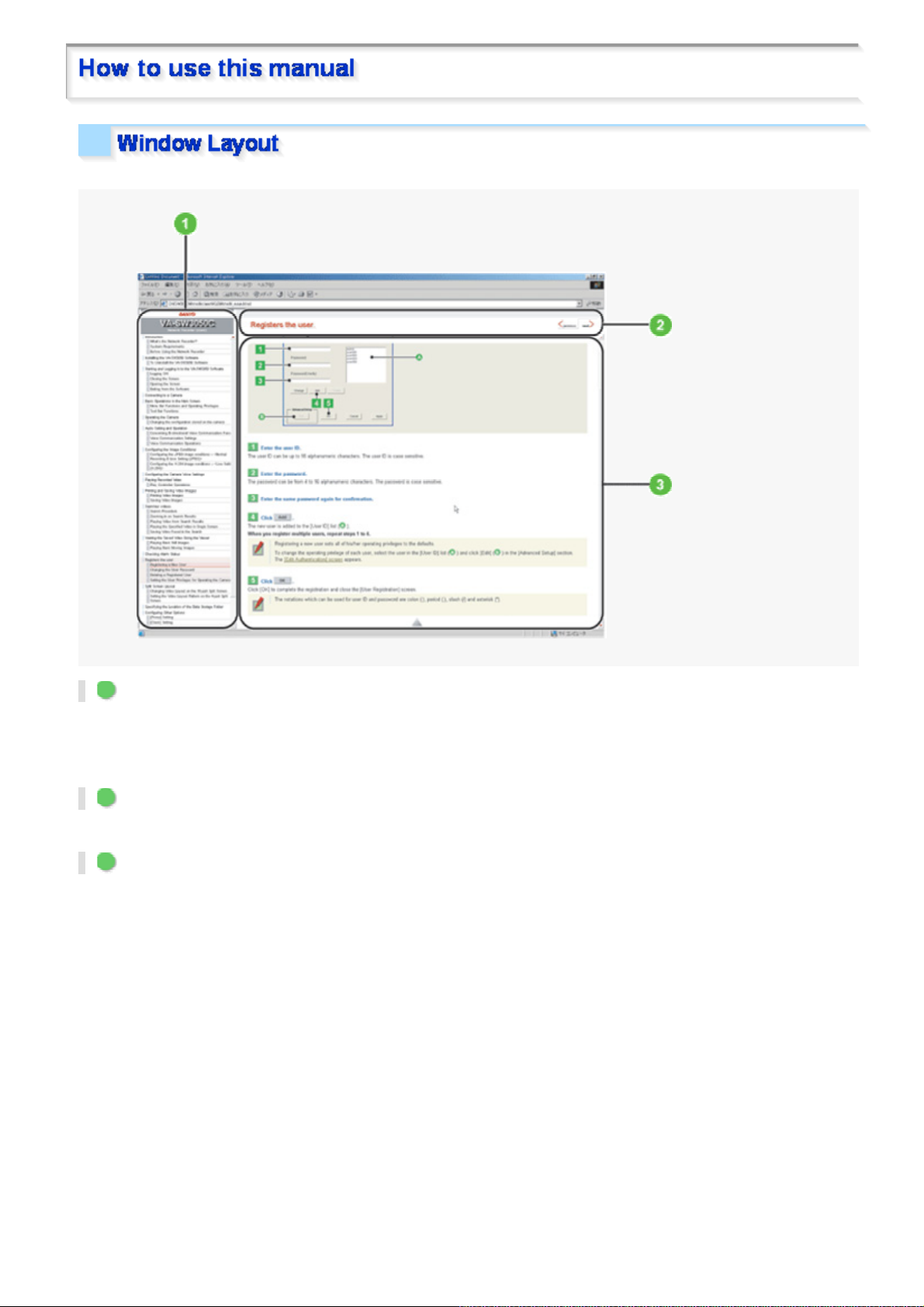
This manual consists of three resident windows:
1 INDEX window
This window shows a table of contents.
The headline of the topic curre ntly opened at the main window is highli ghted, so the current location amon g the
manual can be easily confir me d.
2 TITLE window
This window shows the headline of the c ur rent topic. This TITLE window never scrolls not to hide the headline.
3 MAIN window
This window shows the main detail contents.
Copyright Notice/How to Use This Manual 5/8
Page 7
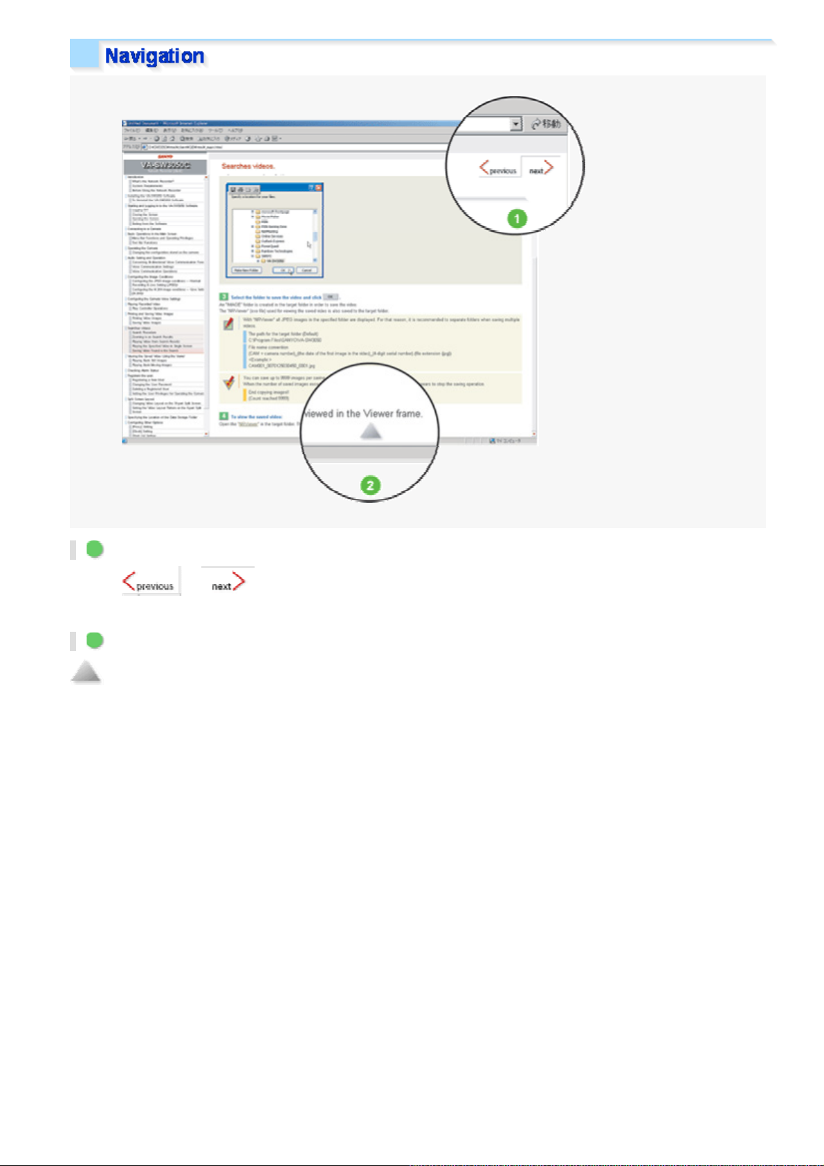
1 Previous/Next
Clicking or on the top right of the TITLE window will display the previous page or the next
page, respectively .
2 Page end
is located at the end of the page.
This mark is also linked to the top of the page. Click on this mark to jump to the top of the page.
Copyright Notice/How to Use This Manual 6/8
Page 8
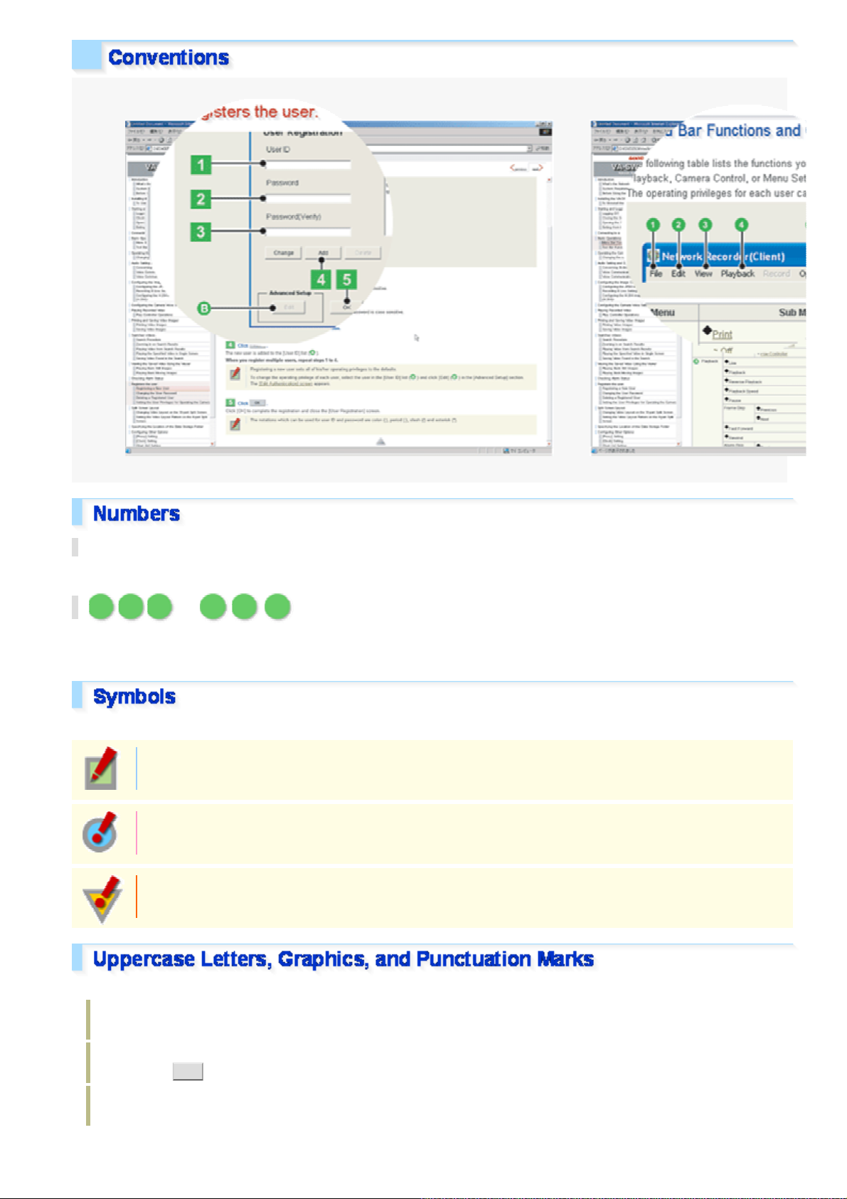
123 ...
Boxed numbers indicate procedural instructions.
123 ... ABC ...
Circled numbers or circled alphabetic letters are us ed in se ct ions that describe screen component names or other
information.
This manual uses the following three kinds of symbols depending on the content of the provided information.
Memo:
Indicates supplementary or related information.
Reference:
Provides references to the associated settings that must be configured on other menu screens.
Caution:
Indicates prohibit ed or restricted operating and se tt ing ins tructions.
This manual uses the following notations to present user-interface related information:
Information such as the screen tit le is represented in all uppercase alphabetic letters, as dis played on the
screen (Example: NETWORK SETTING S).
Information such as opera tion buttons and icons are represen ted as gr aphic s, as displayed on the screen
(Example: SET ).
The names of specific setting items, tabs, dialog boxes and the like ar e enc los ed in s quar e brackets [ ]
(Exam ple : [TITLE]) .
Copyright Notice/How to Use This Manual 7/8
Page 9

The options or values that you se lec t in a pull-down menu or using radio buttons ar e encl os ed in double
quotes “ ” (Example: “ON”, “80”).
Each section describi ng a configuration procedur e begins with a screenshot of the correspon ding initial
configuration screen.
The purpose of this screenshot is to show you the factory default value for each setting item provided on the
screen.
Copyright Notice/How to Use This Manual 8/8
Page 10
VCC-HD2500/HD2500P
Accessing the Camera
Control Panel/Tool Panel
CAMERA SETTINGS
Displaying LIVE video
Transmi tt i n g Image Da t a
Recording
Others
Q&A1/11
Page 11
I cannot access the camer a.
g
1 The camera IP address you entered is wrong.
Enter the correct IP addres s (URL) in th e Web brows er (Internet Explorer).
2 The camera port number you entered is wrong.
If you are using a port number other than 80, enter the correct port number in the Web browser
(Internet Explor er ) .
3 Your have accessed with “http://” where you should be using HTTPS.
When using HTTPS, access with “https://”. Also make sure to enter the port number if you have
changed it to other than 443.
4 Access is restricted by securit y setting (The error message “403 forb idden” is displayed).
Contact your network admin is trator and ask him/her to change the security settings.
I cannot access the camera fro m within m y home/ c omp any network.
1 The PC and camera IP addresses (local addresses) are configured with different subnet masks.
To use a PC and a camera within the same network, their subnet masks must be the same.
Change settings so that the PC and camera hav e the sam e sub net mask.
2 The Web browser you are using is configured to connect to the Internet via proxy server.
Change the Web browser settings so that the use of proxy server is disabled.
3 The address you are trying to acce ss is not a local addr es s .
Enter a local address to access a camera located in the same networ k.
You cannot access a camera by entering a URL (or router
lobal address and camera port number)
registered with the dynamic DNS service or a URL that is compliant with the global address.
I cannot access the camera fro m the Internet.
1 There is a wrong network setting in the camera.
Configure the default gateway correctly. When using the dy nam ic DNS servi c e, chec k whether the
entered DNS server address and dom ain nam e reg is tered with the dynamic DNS service are
correct.
2 Registration to the dynamic DNS service is yet to be done. (When using the dynamic DNS service)
Go to the dynamic DNS service site and check that the address for your camera is correctly
registered.
3 Port forwarding is not configured on your router.
Port forwarding must be configured on your router for you to be able to access a camera from the
Internet. For the configuration method, refer to your router's instruction manual.
Q&A 2/11
Page 12

4 Your router is configured with pac ke t filtering or the like which restricts access from the Internet.
Change the settings in your router to allow access from the Internet. For the configuration met hod,
refer to your router's instruction manual.
5 The IP address you entered is a local address (the one you use at your home).
When accessing via Internet, enter the global address (or the URL registered with the DDNS
service) and port number of t he camera as its IP address.
The camera has been suddenly disconnected.
1 Another user has changed the password.
Configure the passwor d se tt ings again.
2 Another user has changed the camera s ettings.
Access again after a while.
I get stuck at the Login screen.
The password is changed.
Check the password and try agai n.
The access lamp does not go on.
1 The LAN cable that connects directly to the camera is broken.
Connect the LAN cable.
2 The LAN cable has been unplugged.
Connect the LAN cable.
3 The switching hub is turned off.
Turn on the switching hub.
I forgot the camera IP address/port number.
Press the SET button provided on the left-side face of the camera and, on the SELECT MENU
screen, select [FIRMWARE VERSION] to check the firmware version.
Using the supplied “Auto IP Setup” software, execute a camera search.
Q&A 3/11
Page 13

Buttons on the control panel /tool panel do not respond.
g
1 You do not have the required operation privilege.
Some buttons on the control panel/ tool panel are operable only when y ou hav e an adequate
operation privilege. Log in as a user with an adequate operation privilege.
2 You have not configured the required operation sett ings .
The audio controls on the tool panel are operable only when you have confi
ured the audio settings
on the CLIENT SETTINGS screen.
The [DIGITAL PTZ] button is not operable when you have set [DIGITAL PTZ] to “OFF” on the
VIDEO & AUDIO SETTINGS screen.
The Remote Alarm buttons are opera ble only when y ou hav e se t [ALARM OUT 1/2] to “REM OTE”
on the ALARM SETTINGS screen.
The [MENU] button does not respond.
Only the admin and operator1 us er s hav e the operation privilege f or the configuration screens.
Without the required operation privilege, you will be presented with an authenticati on che ck dialog
box when you click the [MENU] button on the live screen.
In this case, you can change the operation privilege by enteri ng a user name with an adequate
operation privilege and its password in the dialog box.
Q&A 4/11
Page 14
I cannot set [SENSE UP] in [IRIS].
You cannot set [SENSE UP] when [SHUT TER] is se t to “SHORT” or “LONG”.
Set [SHUTTER] to “OFF”.
I cannot set [SHUTTER] to “SHORT” or “LO NG”.
You cannot configure the electronic shutter settings if you have set [SENSE UP] in [IRIS].
Set [SEN S E UP] in [IRIS ] to “OFF”.
I cannot turn off the AGC.
1 You cannot set [AGC] to “OFF” when [DAY/NIGHT] is set to “ A UTO”.
Set [DAY/NIGHT] to “COLOR” or “B/W”.
2 You cannot set [AGC] to “OFF” when [SENSE UP] in [IRIS] is set to “ON ”.
Set [SEN S E UP] in [IRIS ] to “OFF”.
Q&A 5/11
Page 15
I cannot display LIVE video.
1 ActiveX control is not installed in your PC.
Install Ac ti ve X .
2 There is network congestion.
It may take some time until the screen can be dis play ed. Please wait.
The message “THE UNIT IS BUSY” appears on the screen if the number of simultaneously
accessible users is alre ady rea ch ed.
3 The version of the installed ActiveX control is old.
When another ActiveX contr ol for network cameras is install ed, video may not be displayed due to
compatibility iss ues between the different versions . Install the H.264 Plug-In inc luded in the
supplied CD-ROM or the latest H.2 64 Plug-In you can download from SANYO CCTV System Web
page.
4 The Web browser you are using for accessing the camera is configured to connect to the Internet
via proxy server.
Some proxy servers block UDPs duri ng H.264 browsing. In this case, either c hange the settings to
browse H.264 using HTTP, or brow se usin g JPEG.
I cannot install the “H.264 Plug-In” included in the supplied CD-ROM.
1 The OS of your PC is not a recommended OS.
The OS must be Windows Vista, Windows XP Home Edition or Windows XP Professional SP2 or
later for the H.264 Plug-I n to run.
2 You are not logged into the PC with administrator privileges.
To install the H.264 Plug-In in a PC, you need OS administrator privileges. If yo u are log ged in with
user privileges, log out and log in again with administrator priv ileges to do the installation.
An error code appears and no LIVE video is dis play ed.
1 The configured IP address or domain name is wrong.
Configure the IP address or domain name correctly.
2 If the address or domain name is correct, then the network connection has timed out.
Use the network when it is not conges ted, or check whether there ar e other applications using th e
network and if there are, stop them for example.
The screen has suddenly sto pped r efres hing.
A camera power or network fault has occu rred.
Q&A 6/11
Page 16
Check the power supply status and/or the network environm ent.
The video image is distorted and cannot be displayed correctly.
1 The maximum bit rate for video streamin g is configured with a value higher than the network
bandwidth.
Lower the resolution and/or image quality.
2 The performance of the PC is low.
Make sure that your PC meets the operation requirements specified in the “Operating Environment”
section.
Or replace the video card in the PC with anot her with higher performance.
The image quality is bad.
The color quality for your PC monitor is configur ed to less than 16 bits.
On the [Display Properties] -[Settings] tab, configure the [Color quality] setting for your PC to 16 bits
or more.
The recording rate is low or the video s tops temporarily.
1 Among the multiple accesses to the camera, some are from narrowband net wor ks.
Change the minimum bit rate for video streaming to a large value.
2 There are multiple accesses or accesses with request for multiple resolutions.
Increasing the number of accesses or simultaneous streamings with different resolutions may
decrease the recording rate and/or image quality. Lower the resolution, image quality, and/or
recording rate.
The recording rate is low at maximum resolution.
The performance of the PC is low.
Make sure that your PC meets the operation requirements specified in the “Operating Environment”
section.
Or replace the video card in the PC with anot her with higher performance.
The LIVE video image is not clear.
1 The camera focus has not been adjusted to the correct position.
Click [FOCUS ASSIST] on the CAMERA SETTING S scr een and r eadjust the camera focus using
the focus assist function.
2 The object is too close to the camera.
Move away the object from the camera.
Q&A 7/11
Page 17

3 Dust, dirt, fingerprin ts, etc. are present on the lens cover. Or the lens is fogged.
Wipe away the dust, etc. with a dry cloth.
The live video display is entirely discolor ed ( A white s ubjec t appears to be colored.)
Adjust the white balanc e.
Click [WHITE BALANCE] on the CAMERA SETTINGS scree n and, in [ WHI TE BALANCE ], select
“MWB”. Then, adjust the white balance so that a white subject appear s to be white.
The LIVE video image is noisy.
1 The background of the object is dark.
Increase the lighting to the monitored environment.
Alternatively, click [DAY/NIGHT] on the CAMERA SETTINGS screen and set [DAY/NIGHT] to
“AUTO” to enable the Day/Night function.
2 The color quality for your PC monitor is configured to less than 16 bits.
On the [Display Properties] -[Settings] tab, configure the [Color quality] setting for your PC to 16 bits
or more.
The image contains white spots or colored light spots.
You are using the camera in a dark place. Or, you are recording a dark object.
White spots or colored lig ht spots may appear on the screen when the camera is used i n a dark
place or monitoring a dark subject. This is a characteristic of the image pickup devic e and is not a
malfunction. Use auxiliary lighting or some other means to illum inate the monitored environment.
Q&A 8/11
Page 18
The e-mail transmission function does not work.
1 On the E-MAIL SETTING screen, incorrect user ID/password information is specified in the
AUTHENTICATION se ction .
Set the correct login ID and password.
2 The server address is wron g. Or connec tion to the server is down.
Check the server address settings.
3 The SMTP server requires authentification.
If [AUTHENTICATION] is set to “NO USE”, the e-mail transmission function does not work when
the SMTP server requires authentification. Contact your network administrator and change the
authentication setting according to the SMTP server setting.
This camera supports the two authentication methods, “SMT P” and “POP3 (POP before SMTP)”.
4 Transfer is blocked by the “Outbound Port 25 Blocking (OP25B)” implemented by your provider .
Select the SMTP authentication for the camera and change the dest ination e-mail server port from
25 to 587.
Use the destination e-mail server of your provider.
I cannot view the image data I rec eiv ed on my cell phone.
Some cell phones have a limit on the size of image data they can handle.
Check the resolution of your cell phone.
Q&A 9/11
Page 19
The camera does not record.
1 No SD memory card has not been installed in the camera.
Install an SD memory card.
2 The SD memory card has not been formatted.
Format the SD memory card on the SD MEMORY CARD screen.
3 Time elapsed from turni ng on the cam er a is less than 5 minutes.
After turning on the camer a, wait 5 minu tes or more bef or e starting to record.
4 The SD memory card is write-protecte d.
Release the write-protection switch on the SD memory card.
5 You may have removed the SD memory card without first stopping the data write.
Format the SD memory card. Further m or e, th e SD memo ry car d may be damaged if you remove it
while it is being accessed. Before removing an SD memory card, stop recording by proceeding as
follows.
<Method for stop recording>
Set [SD MEMORY CARD] to “NO USE” on the SD MEMORY CARD screen.
Or, press the NEAR button provided on the left-side face of the camera for 2 seco nds or mor e.
I cannot play back.
The camera is not equipped with playback functions.
Install the supplied application software “HDC Downloader/ DLViewer” from the supplied CD-ROM.
This application sof tware will allow you to download and play back vid eo data.
Q&A 10/11
Page 20
Upgrade has been terminated.
Upgrade has been interrupted due to power off, network fault, or other pr oblem during the process.
Redo the upgrade by proceedin g as follows.
1 Turn on the camera again.
2 Access the camera again.
3 Check the firmware version on [FIR MW ARE UPDA TE] in OPT IO N SETTING S scr een.
* If the version number is updat ed: Upgrade is complete.
* If the version number is not updated: Redo the upgrade.
The date and time is not adjusted automatically by the NTP server.
1 The GATEWAY settings are not configured correctly.
Select NETWORK and configure the [GATEWAY] settings again.
2 The NTP server address is not configured correctly.
Select CLOCK and configure the [NTP SERVER ADDRESS] settings again.
3 Adjustment by NTP is not set as the method for automatic time adjustment.
Select CLOCK and set [CLOCK ADJUST ] to [ON (NTP)].
The date and time inform ation indicated on the live screen does not reflect the clock sett ings
configured on the [CLOCK SETTINGS] screen.
It is recommended that you delete tempor ar y Int er net files.
To do so, in Internet Explorer, click [Internet Options] in the [Tools] menu and then delete
temporary files, his tory , cook ies, saved passwords, and web form information from the [General]
tab.
Q&A 11/11
Page 21
VCC-HD2500/HD2500P
W
NETWORK SETTINGS
CLOCK SETTINGS
USER REGISTRATION
VIDEO & AUDIO SETTINGS
CAMERA SETTINGS
ALARM SETTINGS
RECORDING
SD MEMORY CARD
E-MAIL SETTINGS
FTP SETTINGS
SECURITY SETTINGS
SCHEDULE SETTINGS
OPTION SETTINGS
orking with Administrator Configuration Screens1/66
Page 22

Click NETWORK in the configuration menu to display the NETWORK SETTINGS screen.
W
On this screen, configure the f ollowing settings as requir ed.
A Configuring basic network settings (NETWORK)
B Configuring DDNS setting (DDNS)
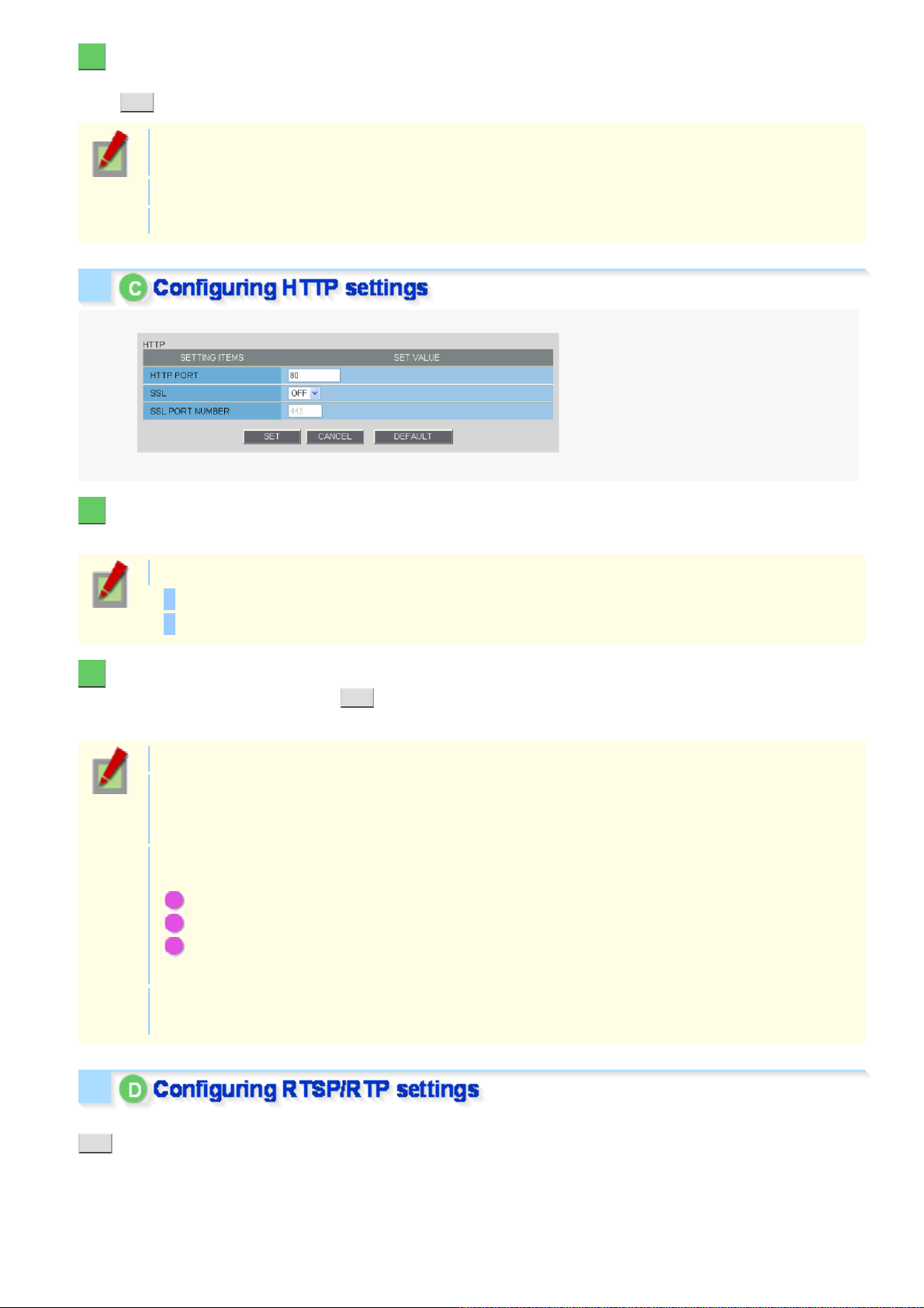
C Configuring HTTP settings
D Configuring RTSP/RTP settings
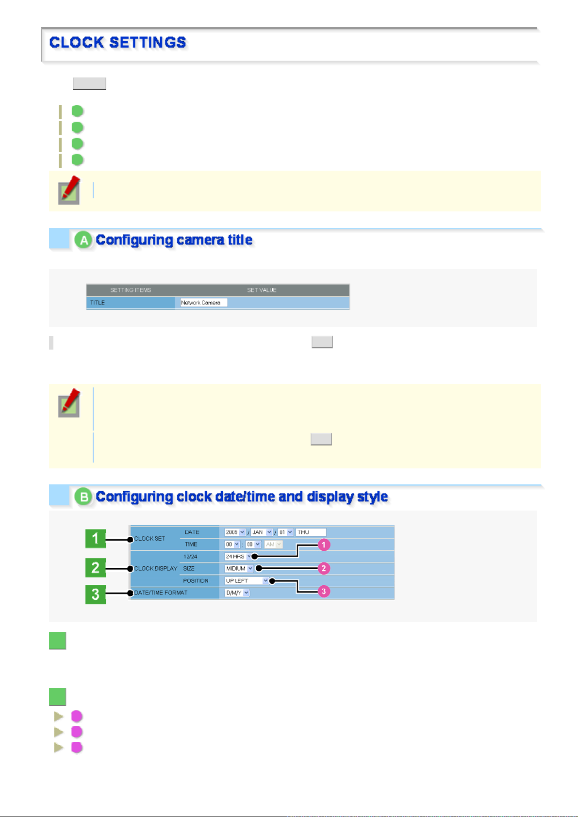
E Configuring access name settings (ACCESS NAME)
F Multicast settings (MULTICAST)
Required operation priv ilege: admin
Before attempting to configure these network sett ings , contact your network admin is trator.
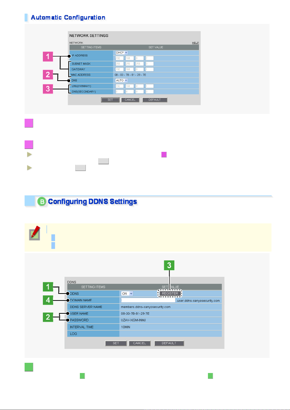
Configure the environment required to connect to the camera via the network by specifying the IP address, subnet
mask, and other informat ion.
1 In [IP ADDRESS], select “FIX” and type the IP address of the camera below it.
2 In [SUBNET MASK] and [GATEWAY], type your subnet mask and gateway addresses,
respectively.
3 In [DNS (PRIMARY)] and [DNS (SECONDARY)], type your primary and secondary DNS
server addresses and click SET .
Because you selected “FIX” in [IP ADDRESS], you specify here fixed DNS server addresses.
After completing the above s teps, click the Close button to once dis c onnec t and then reconnect to the camera to
apply the changes.
To redo the procedure from the beginning, before clicking SET , click CANCEL .
To restore the factory default settings, click DEFAULT .
In [MAC ADDRESS], the MAC address of the camera is sho wn. You ca nnot change this address.
orking with Administrator Configuration Screens 2/66
Page 23
1 In [IP ADDRESS], select “DHCP”.
W
The IP address, subnet mask, and gat eway fields are automaticall y filled.
2 In [DNS], specify how you want to configure the DNS server addresses.
FIX:
AUTO:
After completing the above s teps, click the Close button to once dis c onnec t and then reconnect to the camera to
apply the changes.
Using SANYO's DDNS service, you c an con nec t to the came ra from your Int er net Explorer by simply entering the
registered domain name, instead of the IP address of the camera.
In [DNS (PRIMARY)] and [DNS (SECONDARY)] ( 3 ), type your primary and secondary DNS server
addresses and click SET .
Just click SET . Then, the system sets appropriate DNS server addresses automatically.
To use the DDNS service, configure the following settings.
Specify your DNS server addres s under [DNS SETTINGS] on this screen.
Configure the port forw ar ding on y our ro uter. (For details, refer to your router ' s ins truc tion manual.)
1 In [DDNS], select “ON”.
The [REGISTER] button ( 3 ) appears. The [USER NAME] and [PASSWORD] fields ( 2 ) show the automatically
assigned user name and passwor d, res pec tively.
orking with Administrator Configuration Screens 3/66
Page 24
2 Write down the user name and password shown in the [USER NAME] and [PASSWORD]
W
fields.
This information is required to register your domain nam e.
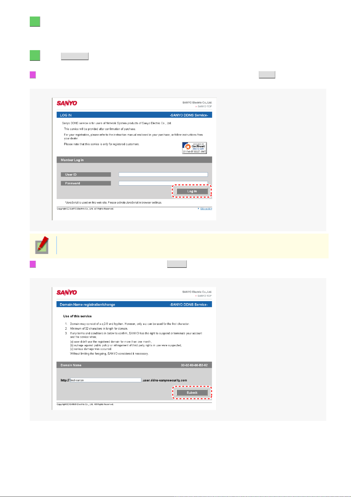
3 Click REGISTER to access the SANYO DDNS service site and register your domain name.
Follow the steps below to regis ter your domain name.
1 On th e LOG IN screen, enter the user name and pass wor d yo u wrote down and click Login .
The Domain Name registration/change screen appears.
SANYO DDNS service site URL:
https://www.ddns-sanyosecurity.com
2 E nter the domain name you want to use and click Submit .
The domain name is registered with the DDNS server.
orking with Administrator Configuration Screens 4/66
Page 25
4 Return to the NETWORK SETTINGS screen ([DDNS]) and, in [DOMAIN NAME], type the
W
domain name you just registered before “.user.ddns-sanyosecurity.com”. Then, click
SET .
The [DDNS SERVER NAME] field is automatically filled (“members.ddns-sanyosecurity.com”), so
you do not need to type it.
The [INTERVAL TIME] setting (access interval to the server) is fixed to “10” (10 minutes).
In the [LOG] field, the DDNS update history log (one entry) is shown.
1 In [HTTP PORT], type your HTTP port number.
Type a number between 1 and 65535.
The default port number depends on whether or not you enable SSL communication in [SS L].
When [SSL] is set to “OFF”: 80
When [SSL] is set to “ON”: 44 3
2 To use SSL communication, select “ON” in [SSL], type your SSL port number in [SSL
PORT NUMBER], and click SET .
Using SSL communication enables the encryption of image transmission.
SSL communication is effective for JPEG streaming images only .
When SSL communication is enabled, you will be presented with a secur ity war ning dialog box when
attempting to access the camera. However, this is not a problem and you can con tinue the operation
by clicking [Yes].
If the message “This page contains both secure and nonsecure items .. .” appears, follow the steps
below to erase it.
1 In Internet Explorer, click [Internet Options] in the [Tool] menu.
2 On the [Security] tab, click the [Cus tom Lev el...] button.
3 In the [Security Settings] dialog box , in the [Settings] section, selec t the “Display mixed conten t”
radio button.
When SSL communication is ena bled, the frame rate of the live streami ng im ages may becom e
slower depending on the resolution setting.
In [RTSP PORT], [RTP PORT (VIDEO)], and [RTP PORT (AUDIO)], type the desired port numbers and click
SET .
orking with Administrator Configuration Screens 5/66
Page 26
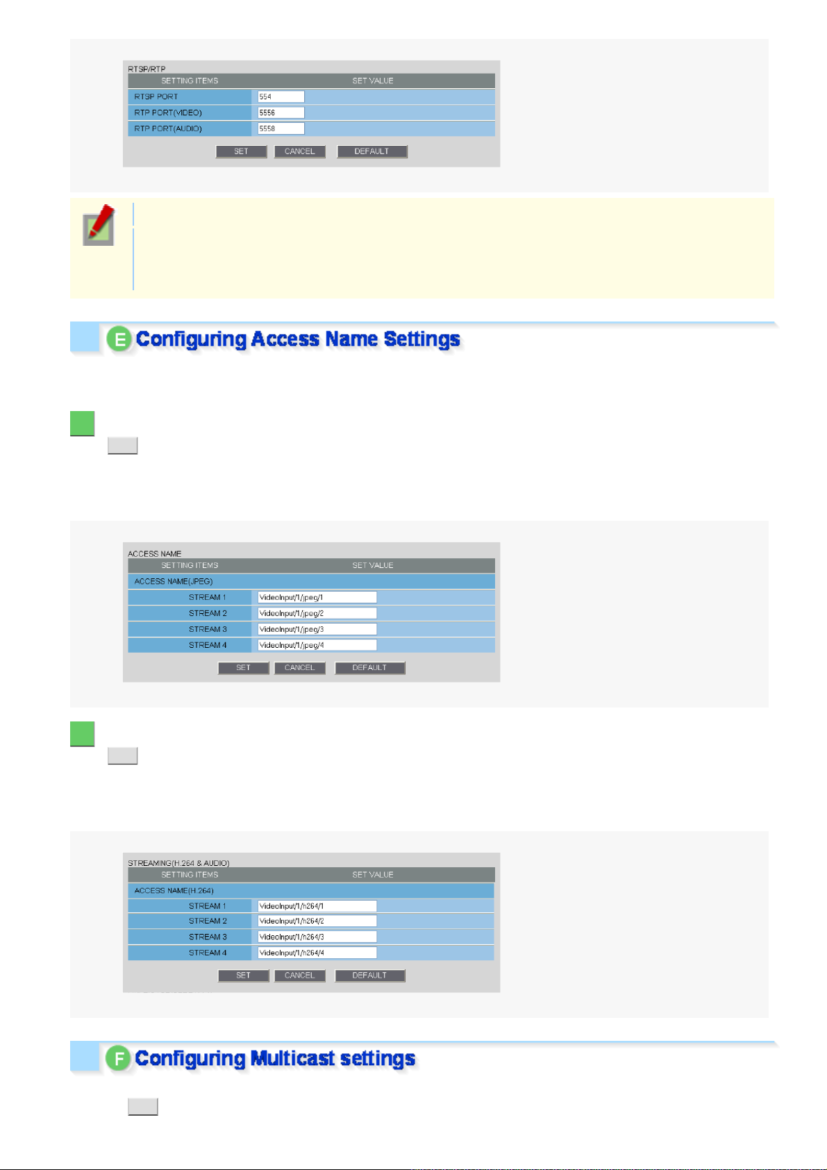
The RTSP port number must be 554 or otherwis e a numbe r in the ran ge of 1 to 6553 5.
W
The RTP port (video and audio) numbers mu st be eve n numbe r s in the ran ge of 1026 t o 65534
(except for numbers between 3874 and 5000, between 9874 and 10000, between 38087 and 38214,
and between 49026 and 49152).
If you intend to access the camera f ro m video viewer or similar software, y ou ma y name each stream (access
name) as you like for easy identif ic ation.
1 Under [ACCESS NAME (JPEG)], type an access name for each JPEG stream and click
SET .
These settings are used for each stream for which you set the codec to “JPEG” on the VIDEO & AUDIO
SETTINGS scree n .
An access name must be specified for each stream (up to 32 alphanumeric characters).
2 Under [ACCESS NAME (H.264)], type an access name for each H.264 stream and click
SET .
These settings are used for each stream for which you set the codec to “H.264” on the VIDEO & AUDIO
SETTINGS scree n .
An access name must be specified for each stream (up to 32 alphanumeric characters).
To enable multicast streaming , configure the multicast addre ss, por t num ber s , and TTL s ett ings for each stream
and click SET .
orking with Administrator Configuration Screens 6/66
Page 27

The multicast RTP port (video and audio) numbers must be even numbers in the range of 1026 to
W
65534 that do not overlap with the unic ast RTP port numbers
(except for numbers between 4000 and 5000, 10000, 10001, 38214, and 49152.)
The multicast TTL must be specified in the range of 1 to 255.
orking with Administrator Configuration Screens 7/66
Page 28
Click CLOCK in the configur ation menu to display the CLOCK SETTINGS screen.
W
Before you start networ k ope ra tion, you need to configure the clock set tings on this screen.
A Configuring camera title
B Configuring clock date/time and display style
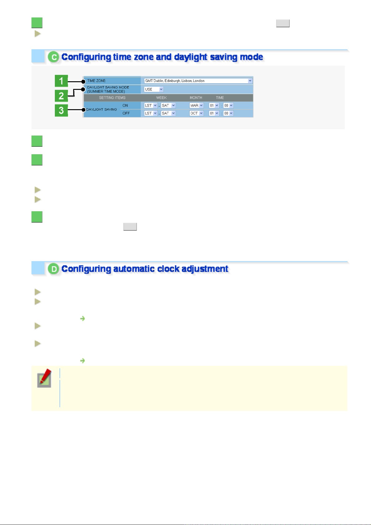
C Configuring time zone and daylight saving mode
D Configuring automatic clock adjustment
Required operation priv ilege: admin, operator 1
Configure the camera title that will be displayed on the live screen and in e-mails, image files, and so on.
In [TITLE], type the desired camera title and click SET .
You can type up to 16 alphanumeric cha ra cter s .
The setting is saved and the camera t itle appears on the live screen.
Note that the camera title cannot include the following symbols : double quote ("), single quot e ('),
ampersand (&), greater-than sign (<), percent (%), backslash (\), less-than sign (>), vertical bar (|),
and semicolon (;).
A warning dialog box will appear when you click SET if the camera title includes any invalid
character.
1 In [CLOCK SET], configure the current date and time in [DATE] and [TIME], respectively.
The configured date and time set tings will be reflected on the camera's built-in clock.
The day of the week is automatically set based on the date and time settings.
2 In [CLOCK DISPLAY], select the clock display style.
1 12/24 (Clock type): 12HRS (12-hour clock) , 24HRS ( 24-hour cloc k )
2 SIZE (Character size):
3 POSITION (Display position):
SMALL, MEDIUM, LARGE
UP LEFT, UP RIGHT, DOWN LEFT, DOWN RIGHT, OFF (Hidden)
orking with Administrator Configuration Screens 8/66
Page 29
3 In [DATE/TIME FORMAT], select the date/time display format and click SET .
W
M/D/Y, Y/M/D, D/M/Y
1 In [TIME ZONE], select the region where the camera is used.
2 In [DAYLIGHT SAVING MODE], select whether or not to use the daylight saving mode.
Although an appropriate setting is automatically selected according to the [TIME ZONE] setting, you can change it
manually.
NO USE:
USE:
Disables the daylight sav ing mode.
Enables the daylight sav i ng mo de.
3 In [DAYLIGHT SAVING], select when to start (in [ON]) and end (in [OFF]) the daylight
saving mode and click SET .
Although an appropriate setting is automatically s elec ted according to the [TIME ZONE] set ting, you can change it
manually.
In [CLOCK ADJUST], select how you want to aut oma tically adjust the camera's int er nal c loc k .
OFF:
ON (NTP):
LOGIN
(PC):
ALARM
IN1:
Disables the clock adjustment function.
Enables automatic clock adjus tment that retrieves the date and time information from the NTP
server.
You need to configure th e NTP settings.
Enables automatic clock adjus tment that retrieves the dat e and time information from the PC
when an admin user logs into it.
Enables automatic clock adjus tment that adjusts the clock to th e spe cified time based on the
signal received from the device connected to the ALARM IN1 terminal.
You need to configure the [CLOCK IN] sett ing.
It is recommended to select “ON (NTP) ” when the cam er a is conne cted to the Internet.
If the camera is not connected to the Internet, select “LOGIN (PC)” or, using the supplied monitoring
software “VA-SW3050Lite”, enable the clock adju stm ent function (24-hour int er va l) in the cloc k
setting.
orking with Administrator Configuration Screens 9/66
Page 30
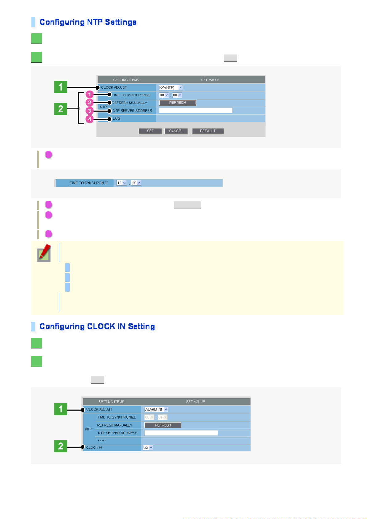
1 In [CLOCK ADJUST], select “ON (NTP)”.
W
2 Configure the required settings shown below and click SET .
1 To automatically adj ust the clock time every day, in [TIME TO SYNCHRONIZE], select t he 24- hour tim e to
which you want to adjust the clock (for example, “10:30”).
2 To adjust the clock to the curr ent t im e, clic k REFRESH .
3 In [NTP SERVER ADDRESS], type the IP addres s or domain name of the NTP server from which you
want to retrieve the date and time informa tion.
4 In [LOG], the last entry of the oper ation log related to automatic clo ck adjustment is shown.
When “ON (NTP)” in [CLOCK ADJUST] is selected, the clock adjustment function adjusts the clock in
the following timings.
When the camera is turned on
At the time selected in [TIME TO SYNCHRONIZE] (every day)
When any change is made to the settings on this screen
To use a domain name, you must specify the DNS serv er addr es s in [DNS SERVER ADDRES S] on
the NETWORK SETTINGS screen.
1 In [CLOCK ADJUST], select “ALARM IN1”.
2 In [CLOCK IN], select the 24-hour time to which you want to adjust the clock (for
example, “22” for 10 p.m.) when the switch connected to the ALARM IN1 terminal turns
on, and click SET .
orking with Administrator Configuration Screens 10/66
Page 31

The clock time will not be adjusted if the difference between the set time and the cur re nt t ime
W
exceeds the range of -29 to +30 minutes.
If you set [CLOCK ADJUST] to “ALARM IN1”, the ALA RM IN1 term inal will serve dedicatedly as a
time adjustment terminal, so you can see only the item [POLARITY] in [AL ARM IN1] on the ALARM
SETTINGS scree n .
orking with Administrator Configuration Screens 11/66
Page 32

Click USER i n the configuration menu to display the USER REGIS TRATION screen.
W
On this screen, you can register new login users, or change or delete existing user data.
A Registering a new user (ADD)
B Changing existing user data (CHANGE)
C Deleting an existing user (DELETE)
Required operation priv ilege: admin, operator 1
Besides the factory def ault users (admin, operator1 , oper ator2, download, and guest ) , you can regi st er up to 20
client users.
1 Click ADD .
The USER REGISTRATION screen appears in a separate window.
A User list
Displays the list of regi s tered us er s .
This list initial ly show s the factory default users (admin, operat or 1, operator2, download, and guest ) .
For these factory default users, you can change the password only .
B [ANONYMOUS USER LOG IN] pull-down menu
Use this pull-down menu to enable/disable anonymous user login.
Selecting “ON” allows all users to log into th e camera without authentication.
orking with Administrator Configuration Screens 12/66
Page 33

In this case, all login user s are regarded as guest users.
W
This means that users will be pres ented with an authentication chec k dialog box if they attempt to
perform any operation beyond the guest user privilege and must enter an adequate user name and
password to proceed.
2 In [USER NAME] and [PASSWORD], type your user name and password, respectively.
Then, in [CONFIRM PASSWORD], type the same password again.
You can type 4 to 32 alphanumeric characters.
3 In [LIVE STREAM], select the check box next to the stream you want to allow this user to
monitor.
You may select two or more check boxes.
You need to configure the video conditions for each stream on the VIDEO & AUDIO SETTING S
screen.
4 In [ACCESS LEVEL], select the operating privilege you want to grant to this user.
For details, see the “Operation Priv ileges” section.
5 In [CLIENT SET], select whether or not to allow the user to change the stream and
password settings on the CLIENT SETTINGS screen, and click SET .
The settings are saved and the USER REGI STRA TI ON sc re en cl os es.
The user list now includes the user y ou jus t regis tered.
In [STREAM SET], specify whether to allow the user to change the live stream setting.
admin:
Does not allow the user to change the live stream setting.
The stream specified in [LIVE STREAM] on this screen is applied.
user:
Allows the user to change the live stre am setting.
The user can change the live stream set ting on the CLIENT SETTINGS screen.
In [PASSWORD SET], specify whether to allow the user to change the password setting.
admin: Does not allow the user to change the pass wor d s ett ing.
The password specified in [PASSWORD] on this screen is applied.
user:
Allows the user to change the passwor d s ett ing.
The user can change the password setting on the CLIENT SETTINGS screen.
orking with Administrator Configuration Screens 13/66
Page 34

1 Select the check box next to the user whose data you want to change and click CHANGE .
W
The user registration screen for the selected user appears in a separate window.
2 Change the desired settings and click SET .
Your changes are saved and reflec ted in the user list.
Select the check box next to the user you want to delete and click DELETE .
The selected user is delet ed from the user list.
You cannot delete the factory default users (admin, operator1, operator2, download, and guest).
orking with Administrator Configuration Screens 14/66
Page 35

Click VIDEO/AUDIO in the configuration menu to display the VIDEO & AUDIO SETTINGS screen.
W
On this screen, configure the conditions of each video stream and the audio you receive from the camera.
A Configuring aspect ratio (ASPECT RATIO)
B Configuring video (VIDEO)
C Configuring audio (AUDIO)
Required operation priv ilege: admin, operator 1
In [ASPECT RATIO], select the aspect ratio (width-to-height ratio) of the video/image by
clicking the corresponding radio button and click SET .
This setting applies to all video/image streams you are configur ing.
16:9 (Landscape), 4:3 (Po r trait)
Clicking SET reboots the camera.
This camera supports mult i- s tream video transmission, allowing you to register up to four video /im age streaming
condition patterns.
Thus, you can reduce the load of the ent ir e system by choosing optimal settings for your applicatio n, such as
recording or live video monitoring.
When you have added, changed, or delet ed registered information, be sure to click SET in the
stream list. Otherwise, changes you made won't be saved and reflect ed in the stream settings.
Clicking SET reboots the camera.
Note that the number of register able streams and configurable settings may be affected by other
stream settings.
The camera provides two factory default stream patterns (STREAM1 and STREAM2. Besides these, you can
register up to two custom stream patterns (STREAM3 and STREAM4).
1 Click ADD .
The stream registrat ion s c re en appear s in a sepa ra te window.
“STREAM3” will be automatically set for the first additional stream.
orking with Administrator Configuration Screens 15/66
Page 36

In the stream list ( A ), the currently registered streams are shown.
W
Initially, this list shows video settings for STREAM1 and STREAM2.
2 Configure the video/image conditions for the stream you want to register and click SET .
The settings are saved. The stream list now includes the stream you jus t registered.
1 In [NAME], type the stream name you want.
You can type up to 64 alphanumeric cha ra cter s .
2 In [CODEC], select the image/video compression format.
JPEG, H.264
3 In [RESOLUTION], select the display resolution.
The available options vary depending on your selections in [ASPECT RATIO] and [CODEC].
JPEG (16:9):
JPEG (4:3):
H.264 (16:9):
H.264 (4:3):
4 In [DIGITAL PTZ], enable or disable the digital PTZ function.
1920×1080, 1280×720, 1024×576, 640×360
2288×1712, 1600×1200, 1280×960, 1024×768, 800×600, 640×480 , 320×240
1920×1080, 1280×720, 640×360, 320×180
1600×1200, 1280×960, 1024×768, 640×480, 320×240
To display areas of subject you c lipped, or use the digital PTZ function on the live screen, select “ON”.
You cannot select “ON” if you selec ted “H.264” in [CODEC].
Selecting “ON” in [DIGITAL PTZ] fixes the [RESOLUTION] value to a VGA-equi v alent size (“640×
360” in 16:9 aspect ratio or “640×480” in 4:3 aspect ratio).
5 If you selected “H.264” in [CODEC], in [GOP], enter a GOP value.
This enables you to specify t he GOP sett ing for the H.264 video stream.
6 In [FRAME RATE], select the frame rate of the stream.
The available options vary depending on your selection in [CODEC] and your camera model.
orking with Administrator Configuration Screens 16/66
Page 37

JPEG:
W
H.264:
7 In [PRIORITY], select whether you put priority on the video/image quality or the bit rate.
QUALITY, BITRATE
VCC-HD2500: 0.1ips, 0.2ips, 0.5ips, 1ips, 3ips, 5ips, 10ips, 15ips, 30ips
VCC-HD2500P: 0.1ips, 0.2ips, 0.5ips, 1ips, 2.5ips, 5ips, 8ips, 12.5ips, 25ip s
VCC-HD2500: 5ips, 10ips, 15ips, 30ips
VCC-HD2500P: 5ips, 8ips, 12.5ips, 25ips
If you selected “QUALITY”, in [PICTURE QUALITY], specify the video/image quality.
Then, the system shows an appropriate bit rate depending on the sel ec ted quality.
BASIC, NORMAL, ENHANCED, FINE, SUPER FINE
If you selected “BITRATE”, in [BITRATE], the system shows an appropriate bit rate for you.
Type the bit rate directly , if you want to change it.
8 In [STREAM UTILIZATION], the encoder stream utilization rate is automatically shown.
The stream utilization rate cannot exceed 100%. Configure stream conditions based on the displayed stream
utilization rate.
Use the encoder stream utili zation rate indicated unde r [STRE AM UTILIZATION] only as a guide.
3 Click SET in the stream list.
The camera will reboot and the settings you configured will be enabled.
You may also choose to change the factor y -default stream settings (STREAM1 and STRE AM2).
1 Select the check box next to the stream for which you want to change data and click
CHANGE .
The stream registrat ion s c re en for the selected stream appears in a separ ate window.
2 Change the desired settings and click SET .
Your changes are saved and reflec ted in the stream list.
orking with Administrator Configuration Screens 17/66
Page 38

3 Click SET in the stream list.
W
The camera will reboot and the sett i ngs yo u configured will be enabled.
1 Select the check box next to the stream you want to delete and click DELETE .
The selected stream is delet ed from the stream list.
2 Click SET in the stream list.
The camera will reboot and the sett i ngs yo u configured will be enabled.
Configure the conditions of the audio you receive from the camera.
1 In [MIC SENSITIVITY], specify the microphone sensitivity.
Select the sensitivity of the microphone connected to t he camera from 8 levels.
+4, +3, +2 , +1 , 0, –1 , – 2 , –3
2 In [FILTER(500Hz)], enable or disable the audio filter.
The audio filter reduces the 500 Hz or less frequency components of the audio.
A filter option with a lower negative dB value produces larger ef fects.
ON(-3dB), ON(-6 dB), O FF
3 In [OUTPUT LEVEL], select the desired audio output level and click SET .
Here, you specify the gain value of the audio output amplifier from the following 4 levels.
+2, +1, 0, –1
orking with Administrator Configuration Screens 18/66
Page 39

Click CAMERA in the configur ation menu to display the CAMERA SETTINGS screen.
W
The CAMERA SETTINGS screen includes a sub menu from which you can access 14 camera setti ngs to
configure the monitoring and other conditions of the camera.
Required operation priv ilege: admin, operator 1
The CAMERA SETTINGS sub menu offers a list of camer a settings.
1 Sub menu: Click one of the menu items in the sub menu to jump to the des ir ed cam era settings.
2 DEFAULT : Click this button to reset all the settings you configured for the selected view (CAM1/CAM2) to the defaults
(factory settings).
This area shows a series of camera settings. You can use the vertical scroll bar and scroll buttons to scroll the
settings up and down.
For each camera setting configuration section, th e following buttons are provide d.
orking with Administrator Configuration Screens 19/66
Page 40

1 SET : Click this button when finished configuring the camera settings you accessed by clicking each sub menu
W
item.
2 CANCEL : Click this button before cli cking SET to restore the previous settings.
3 DEFAULT : Click this button to reset the settings on the camera configuration screen to the defaults (factory settings).
4 HELP: Click this to display a menu from which you can display the explanation of each configur ation screen on the
HELP screen.
Configuration Summary for Each Sub Menu Item
Sub Menu Operation Application
VIEW You can have two patterns of view settings (CAM1/CAM2) by configuring the
1
2
IRIS Configure the lens iris. VIEW
WHITE
3
BALANCE
4 BLC Configure the backlight compensation f unction. VIEW
5 SHUTTER Configure the electronic shutter. VIEW
6
AGC Configure the g ain of the video signal. VIEW
DAY/NIGHT Configure the Day/Night function that automatically switches the camera between color
7
8 APERTURE Configure the contour compensation function. VIEW
VIVID COLOR
9
EFFECT
10 GAMMA Configure the gamma correction level. VIEW
11 DNR Configure the noise reduction function. VIEW
12 FOCUS ASSIST Configure the focus assist function to adjust the focus. Common
13 MIRROR Configure the mirror function to flip the subject on the monitor. Common
monitoring conditions through sub menu items “2 IRI S” to “11 PRIVACY MASK”.
Adjust the white balance. VIEW
and black-and-whi te vi deo m odes depending on the luminance of the target.
Configure the color saturation compensation function. VIEW
VIEW
VIEW
PRIVACY MASK Configure the privacy mask settings to mask portions of the subject you want to hide
14
for privacy protect ion.
Common
“Application” in the above table means the following:
VIEW: The configured settings will be applied to “CAM1” or “CAM2”, whicheve r you selec ted under
[VIEW].
Common: The configured settings will be applied commonly to “CAM1” and “CAM2” selected
under [VIEW].
You can view how your changes affect the video im age in r eal time.
You can configure two patterns of monitoring conditions .
For example, select “CAM1” t o con figure the normal live monitoring conditions for daytime use and select “CAM2 ”
to configure the monitoring condit ions with the Day/Night funct ion for nighttime use, res pec tively. Thus, you can
switch the monitoring c onditions depending on your needs.
orking with Administrator Configuration Screens 20/66
Page 41

Configuring Monitoring Conditions
W
In [VIEW], select “CAM1” or “CAM2” and then configure the monitoring conditions by clicking each menu item in
the sub menu.
Switching between Monitoring Conditions
In [VIEW], select “CAM1” or “CAM2”. The monitori ng conditions conf igured for the selected view sett ing ar e now
applied to the camera.
Configure the lens iris accor ding to the brightness of the subject displayed on the screen.
The configured settings will be applied to “CAM1” or “CAM2”, whichev er you sele cted under [VIEW].
1 In [SENSE UP], select the electronic sensitivity boosting power.
OFF, x2, x4, x8, x16 , x32
Enabling the electronic sensitivity boosting function causes the following:
The exposure time of the camera's im age sensing device will be increased automatically in dark
situations. This may result in conspicuous afterimages, blurs, and white spots if the subject
includes any moving object.
If [DAY/NIGHT] is set to “AUTO”, the electronic sensitivity boosting function will work only for
black/white video images .
[SHUTTER] is set to “OFF”, preventing you from configuring the electronic shutter setting
(“SHORT” or “LONG”).
No motion sensor type can be select ed in [MOT IO N] on th e ALARM SETTINGS screen.
You cannot configure the electronic sensitivity boosting function in the following case:
When [AG C ] is set to “OFF” .
A motion sensor type is selected in [MOTION] on the ALARM SETTINGS screen.
2 In [LEVEL], select the video signal level and click SET .
0 (dark) to 100 (bright)
orking with Administrator Configuration Screens 21/66
Page 42

Select and configure the white balance adjustment mode.
W
ATW: Auto trace white balance
AWC:
3200:
5600:
FLUORESCENT:
MWB:
The configured settings will be applied to “CAM1” or “CAM2”, whichev er you sele cted under [VIEW].
Auto trace white balance (ATW) automatically adjusts th e white balance to provide optimal colors , even if the light
source for the target objec t is changed.
Enable the smart ATW function here bec aus e A TW may not produce desirable results if a single solid color
occupies a large part of the subject.
Auto white balance control
Fixed white balance (for indoors)
Fixed white balance (for outdoors)
Fixed white balance (for fluorescent lighting)
Manual white balance
1 In [WHITE BALANCE], select “ATW”.
2 In [SMART ATW], select “ON” and click SET .
The camera now adjusts the white balance automatically based on the color information on the subje ct.
Do not use the smart ATW function in environm ents where the color temperatur e fluctuates.
In an outdoor environment for example, smart ATW may not produce desirable results because the
color temperature f luc tuates depending on the time of the day (at sunrise, daytime, and sunset),
weather (sunny or cloudy), and other conditions.
1 In [MASKING], select “ON” and click SET .
The ATW masking screen appears.
Mask the light source by the follo wing pr ocedure.
orking with Administrator Configuration Screens 22/66
Page 43

2 Drag the mouse over the live video image to select the area you want to mask.
W
The masked area is indicated by blue-bordered grid cells each containing the letter “M”.
You can mask more than one portion of the live image.
You can click one grid cell afte r ano ther to set or cancel the masked area cell by cell.
To deselect a block of grid cells in the masked area, right-click one of grid cell and drag the mouse.
3 Click SET and then BACK .
The settings are saved and you return to the sub menu.
Use AWC if auto trace white balance (ATW) does not reproduce a natural white balance.
AWC allows you to automatically adjust the white balance by simply cli cking SET with t he camera lens dir ec ted
toward a white wall, white paper and t he l ik e.
1 In [WHITE BALANCE], select “AWC”.
2 Direct the camera lens toward a white wall, white paper and the like and, in [AWC LOCK],
click SET .
If the white balance adjust ment does not reproduce desirable r es ults, click SET again.
You need to follow the above steps also to re- adjust the white balance when the lighting conditions have been
changed.
To fine-tune the white balanc e aft er this adjustment, in [GO TO MWB], click SET .
You can set the color temperature to a fixed value.
orking with Administrator Configuration Screens 23/66
Page 44

In [WHITE BALANCE], select the desired fixed white balance mode and click SET .
g
W
3200:
5600:
FLUORESCENT:
Use the following procedure to manually adjust the gain value s for the re d and blue s ignals.
For indoors (Fixes the color temper ature to 3200K.)
For outdoors (Fixes the colo r temp er ature to 5600K.)
For fluorescent lighting (Fixes the color temperature to 4200K.)
1 In [WHITE BALANCE], select “MWB”.
2 In [RED] and [BLUE], specify the gain values for the red and blue signals, respectively,
and click SET .
ht) to 255 (dark)
RED:
BLUE:
You can use the backlight compensati on (BLC) function to make the subject easil y visible under strong back light
conditions.
OFF:
MULTI:
CENTER:
MASKING:
FACE:
Multi-spot evaluative metering compensates for the backlighting problem by evaluating the photometry of the
entire screen.
0 (li
0 (light) to 255 (dark)
Disables the backligh t comp ensation function.
Selects the multi-s pot evaluative metering mode.
Selects the center-weighted evaluative metering mode.
Selects the light source mask ing m ode.
Selects the face detection backlight compensation mode.
The configured settings will be applied to “CAM1” or “CAM2”, whichev er you sele cted under [VIEW].
orking with Administrator Configuration Screens 24/66
Page 45

1 In [BLC], select “MULTI”.
W
2 In [BLC WEIGHT], select the backlight sensitivity.
0 (low sensitivity) to 15 (high sensitiv ity)
3 In [BRIGHT], select the compensation level for the brightness of the backlighting and
click SET .
0 (low brightness compen sa tion) to 15 (high brightness compen sa tion)
Center-weighted average metering compensates for the back lighting problem by measuring the photometry of the
specified area intensiv ely.
Configure the position and s ize of the center metering area.
1 In [BLC], select “CENTER” and click SET .
The BLC center/window weighting setting screen appear s , showing a rectangle representing the center metering
area in the center of the screen .
2 Drag the rectangle to set the center metering area in position.
Center-weighted average metering may not be set depending on the position of the center metering
area.
3 Resize the center metering area.
To resize the center metering area, place the mouse pointer over the borde r of the area and then drag it.
orking with Administrator Configuration Screens 25/66
Page 46

4 Configure the metering weight values for the four surrounding metering areas (TOP,
W
BOTTOM, LEFT, and RIGHT).
Select a weight value for each of these metering areas depending on the installation environment.
0 (minimum) to 7 (maximum)
The weight value for the center metering area ([CENTER]) is fixed to “7”. You cannot change this
value.
The brightness value represents the weight for each area and therefore does not affect the actual live
video image from the camera.
5 Click SET and then BACK .
The settings are saved and you return to the sub menu.
You can use light source maski ng to comp ens ate for backlighting problems with human or other objects in the
subject, by masking the light source in a bright background.
1 In [BLC], select “MASKING” and click SET .
The BLC masking screen appears.
2 Drag the mouse over the live video image to select the area you want to mask.
The masked area is indicated by blue-bordered grid cells each containing the letter “M”.
You can mask more than one portion of the liv e ima ge.
orking with Administrator Configuration Screens 26/66
Page 47

You can click one grid cell afte r ano ther to set or cancel the masked area cell by cell.
W
To deselect a block of grid cells in the masked area, right-click one of grid cell and drag the mouse.
3 Click SET and then BACK .
The settings are saved and you return to the sub menu.
Follow the step below to perform backlight compensation when a human face is detected.
A human face may not be detected if obscured by a hat, sung las s es , or mask, or if the monitoring angle is not
appropriate.
In [BLC], select “FACE” and click SET .
With either of the following settings, backligh t comp ens ation will not work even if any human face is
detected.
[AGC] is set to “OFF”.
[SHUTTER] is set to “SHORT” or “LONG”.
Configure the electronic shutt er or ele ct r onic ir is se tt ings ac c or ding to the movement and lumina nc e leve l of th e
subject.
OFF: Disables the electronic shutter or elec tronic iris function.
SHORT:
LONG:
EI:
The fast shutter mode has a shorter exposure time than the field storage time.
Configuring the fast shutter mode enables you to capture quic k motion in the subject.
Enables the fast shutter mode.
Enables the long exposure s hutter mode.
Electronic i r is
The configured settings will be applied to “CAM1” or “CAM2”, whichev er you sele cted under [VIEW].
You cannot select “SHORT” to configure the fast shutter mode if the electronic sensitivity boos ting
([SENSE UP] in [IRIS]) is enabled.
orking with Administrator Configuration Screens 27/66
Page 48

1 In [SHUTTER], select “SHORT”.
W
2 In [SHUTTER SPEED], select the desired shutter speed and click SET .
VCC-HD2500P:
VCC-HD2500:
Each of the above shutter speed values represents the denominator “n” of the fraction 1/n. For
example, selecting “500” means to set a shutter speed of 1/500 second.
The long exposure shutter mod e has a longe r exposure time than the field storage ti me .
The long exposure shutter mod e inc re as es the se ns itivity of the camera to make the subjec t brighter.
You cannot select “LONG” to configure the long exposure shutte r mode if the electronic sensitivi ty
boosting ([SENSE UP] in [IRIS]) is enabled.
25, 50, 120, 250, 500, 1000, 2000, 4000, 10000
30, 60, 100, 250, 500, 1000, 2000, 4000, 10000
1 In [SHUTTER], select “LONG”.
2 In [SHUTTER SPEED], select the desired shutter speed and click SET .
x1, x2, x4, x8, x16, x32
Each of the above shutter speed values represents a multiple of the field storage time. The higher
the value, the longer the exposure time.
Setting an excessively long ex pos ure time may result in ghosts, blurs and white spots if the subject
includes any moving object.
The electronic iris controls both the AGC and the shutter speed to adjus t th e exp os ur e.
In [SHUTTER], select “EI” and click SET .
If you are using an auto iris lens, the electronic iris will acti va te aut om atically at the open end of the
aperture to adjust the expo su re even when [SHUTTER] is set to “OFF”.
orking with Administrator Configuration Screens 28/66
Page 49

Configure the video signal gain value automatically or manually.
W
Automatically configuring gain value using AGC
Manually configuring gain value
Auto Gain Control (AGC) is a function that automatically adjusts the gain value of the camera's vid eo
signal amplifyi ng ci rcuit according to the brightness of th e subject to maintain a constant signal
output.
The configured settings will be applied to “CAM1” or “CAM2”, whichev er you sele cted under [VIEW].
1 In [AGC], select “ON”.
2 In [MAX GAIN], select the maximum gain level for AGC and click SET .
Selecting a higher gain lev el will im prove the camera sensitivi ty in a dar k condition, but increase the noise as well.
NORMAL:
MIDDLE:
HIGH:
For normal subject
For slightly dark subjec t
For dark subject
The maximum gain value varies depending on the Day/Night mode.
If you set [AGC] to “OFF”, you cannot enable the electronic sensitivity boosting function ( in [SE NS E
UP] in [IRIS]).
You cannot select “OFF” in [AGC] if the Day/Night function ([DAY/NIGHT]) is set to “AUTO” or the
electronic sensit iv ity boosting ([SENSE UP] in [IRIS]) is enabled.
1 In [AGC], select “OFF”.
2 In [GAIN SETTING], select the gain value of AGC and click SET .
0dB, 3dB, 6dB, 9dB, 12dB, 15dB, 18dB, 21dB, 24dB, 27dB, 30dB, 33dB, 36dB, 39dB, 42dB
orking with Administrator Configuration Screens 29/66
Page 50

The Day/Night functio n improves the camera's sensitivity by automatically switching th e camera to t he co lor mode
W
in bright conditions and to the black-and-white mode in dark situations.
Using this function enab les 24-hour surveillance with clear video im ages ev en dur ing nighttime or in dark loc ations.
You may also fix the camera to the color or black-and-white video mode with out using the Day/Night function.
Automatically switching camera between color and black-and-white video modes using Day/Night
function
Switching camera between color and black-and-white video modes when an external control signal is
received
Fixing camera to color or black-and-white video mode
The configured settings will be applied to “CAM1” or “CAM2”, whichev er you sele cted under [VIEW].
In AUTO mode, turning off the camera in the black-and-white mode and then tu rn ing it back on again
switches it to the color mode.
The focused position may di ff er between the color and black-and-wh ite modes.
When using infrared lighting in the black-and-white mode, the camera may switch to the color mode
due to strong reflection from objects in the subject. In thi s case, adjust the infrared lighting to prevent
the switching of video to the color mode.
1 In [DAY/NIGHT], select “AUTO”.
If you select “AUTO”, you cannot set [AGC] to “OFF”.
2 In [LEVEL], select the luminance level at which the video mode is switched and click
SET .
HIGH:
MIDDLE:
LOW:
ADJ:
Manually Configuring Mode-Switching Luminance Level (ADJ)
You can select a luminance level between 1 and 7 for both the color to black-and-white switching and black-andwhite to color switching. Swi tching occurs in darker conditions as the luminance level increases .
Sets a high luminance level (to inc r eas e the time during which the camera operates in the blackand-white mode).
Sets the luminance level to halfway between “LOW” and “HIGH”.
Sets a low luminance level (to incr ease the time during which the camera operates in the color
mode).
Enables the manual adjustment of the luminance level.
orking with Administrator Configuration Screens 30/66
Page 51

COLOR→B/W
W
Select the luminance leve l at which s witching occurs from the color mode to the black -and - white mode.
B/W→COLOR
Select the luminance leve l at which s witching occurs from the black-a nd-white mo de to the colo r mode.
Changing one of these settings als o c hanges the other setting based on the dif ference.
To prevent hunting in infrar ed (IR) lighting, set these lum inanc e lev els to widely different values.
Using one of these alarm input term inals as the Day/Night switching terminal, however, enables the camera to be
switched between the colo r and black-and-white video modes when an external control signal is received.
1 In [DAY/NIGHT], select “COLOR”.
2 In [EXT ALARM], select the desired alarm input terminal and click SET .
ALARM IN1:
ALARM IN2:
OFF:
You need to enable the ALARM IN1/2 terminal and configure the signal pol ar ity in [POLARITY] on
the ALARM SETTINGS screen.
Depending on the [POLARITY] setting, the camera will be switched between the color and black-andwhite video modes as follows (commonly applied to CAM1 and CAM2):
If you set [EXT ALARM] to “ALARM IN1” or “ALARM IN2”, the cor r es ponding alarm input terminal will
serve dedicatedly as a Day/Night switching terminal, so you can see only the item [POLARITY] on
the ALARM SETTINGS screen.
Sets the ALARM IN1 terminal as the Day/Ni ght switching terminal.
Sets the ALARM IN2 terminal as the Day/Night switching terminal.
Fixing Camera to Color Video Mode
If [POLARITY] is set to “NO”: Colo r mode when open; Black-and-white mo de when cl os ed
If [POLARITY] is set to “NC”: Color mo de when cl os ed; Black-and-white mode when open
orking with Administrator Configuration Screens 31/66
Page 52

Fixing Camera to Color Video Mode
W
In [DAY/NIGHT] and [EXT ALARM], sel ec t “COLOR” and “OFF”, respectivel y, and cl ic k SET .
Fixing Camera to Black-and-White Video Mode
In [DAY/NIGHT], select “B/W” and c lic k SET .
You can use the contour compensation function to make the whole video image clearer.
Select “ON” in [APERTURE] and an appropriate correction level in [LEVEL] and click SET .
The higher the correction level, the greater the correction effect.
1 to 15
The configured settings will be applied to “CAM1” or “CAM2”, whichev er you sele cted under [VIEW].
Use the color saturation compensation function to improve the vividness of the color.
orking with Administrator Configuration Screens 32/66
Page 53

In [VIVID COLOR EFFECT], select “ON” and click SET .
W
The configured settings will be applied to “CAM1” or “CAM2”, whichev er you sele cted under [VIEW].
Set the gamma correction lev el to adjust the contrast or brightnes s l ev el.
In [GAMMA], select the gamma correction level and click SET .
0.45:
1:
MODE1:
MODE2:
Configure the DNR (Digital Nois e Reduc tion) function to reduc e nois e at low conditions.
Gamma correction level = 0.45
Gamma correction level = 1
Increases the contrast of the whole subject.
Increases the contrast in dark areas further.
The configured settings will be applied to “CAM1” or “CAM2”, whichev er you sele cted under [VIEW].
Selecting “MODE1” or “MODE2” may result in excessively bright images depending on the target
object.
In [DNR], select “ON” and click SET .
The configured settings will be applied to “CAM1” or “CAM2”, whichev er you sele cted under [VIEW].
Enabling the DNR function may c aus e ghos ts and blur s if t he su bjec t includes any moving object,
which results in low resolution.
orking with Administrator Configuration Screens 33/66
Page 54

Clicking [FOCUS ASSIST] in the configuration menu displays the [FOCUS ASSIST] screen.
W
If you have already completed focus adjustment on the camera, you do not need to follow the adjustment
procedures described here.
You may also configure the back focu s position switching mode as requir ed to aut om atically adjust the back focus
position when switching between the color and black-and-white video modes.
The configured settings will be applied commonly to “CAM1” and “CAM2” selected under [VIEW].
You can fine-adjust the focus from the configuration menu.
It is recommended to roughly adjust the focus using the lens levers and the buttons provided on the left-side face
of the camera during installation.
The focus must be readjusted if the camera has lost focus due to difference in the subject distance or
ambient temperature, the deterioration of the lens and ins tallation environm ent, and the like that have
been caused over the years.
1 Select the [MANUAL] check box.
You can now operate the NEAR , FAR , DEFAULT , and ONE PUSH buttons.
2 Click ONE PUSH to focus on the subject.
The camera automatically foc us es on the subject. Note that the color of the status indicat or ( A ) “FOCUSING”
turns from black to orange.
If the camera fails to focus on the subj ec t, the s tat us indicator ( A ) will show “ERROR”. In this case, manually
adjust the focus (in Step 3 ).
3 Click NEAR / FAR to focus on the subject.
The back focus position has been changed.
To restore the default back focus position during re-adjustment etc., click DEFAULT .
While the camera is initializ ing the back focus position, the stat us indic ator ( A ) shows
“INITIALIZING”.
orking with Administrator Configuration Screens 34/66
Page 55

4 Deselect the [MANUAL] check box.
W
Be sure to deselect the check box to prevent the loss of f oc us due to wrong operation.
The check box is automatically des elected if you switch from the focus adjustment screen to another
screen.
Follow the steps below to reduce the loss of camera focus that may occur when the Day/Night function is enabled.
In [COLOR/B/W], select the back focus position switching mode. When finished, click SET and
then BACK .
Select the mode suitable for your lens.
AUTO (for lens that does not
support infrared focusing):
FIX (for lens that supports infrared
focusing):
Use the mirror function to electronically flip the displayed subject.
If you installed the camera ups ide down or intend to monitor the subjec t in the mirr or , configure the following
settings according to the installation environment of the camera.
Adjusts the camera to the last-set back focus position each time
switching to the color/ blac k -and-white video mode occur s.
Fixes the camera to the last- se t back focus position regardless of
switching to the color/ blac k -and-white video mode.
In [MIRROR], select the desired mirror mode and click SET .
Disables the mirror mode (norm al vi deo) .
OFF:
Flips the video vertically and horizontally.
HV:
Flips the video horizontally.
H:
Flips the video vertically .
V:
The configured settings will be applied commonly to “CAM1” and “CAM2” selected under [VIEW].
orking with Administrator Configuration Screens 35/66
Page 56

You can configure the privacy mask settings to hide specific portions of surveillance video for privacy protection.
W
When a privacy mask is set, the resolution, frame rate, and image quality of the live video image may be limited.
The configured settings will be applied commonly to “CAM1” and “CAM2” selected under [VIEW].
1 Click [PRIVACY MASK] in the sub menu.
The PRIVACY MASK SETTINGS screen appears.
The mask setting screen sho ws the vi deo at t he angle of view that you see on the live screen.
On the mask setting screen, you can per form digital zooming. For details , refer to the “Using Digital
PTZ Function” section.
2 Drag the mouse over the live video image to select the area you want to mask.
A mask pattern appears over the selected area.
You can set up to eight mask patterns on the screen.
To select a mask pattern, just click on it. The selected mask pattern is shown with a yellow green
border.
To move a mask pattern, select it and then drag the mouse. To resize a mask pattern, place t he
mouse pointer over its border and then drag the mouse.
To delete a set mask pattern, click the DELETE button corresponding to the pattern number or drag
it out of the screen.
3 Select the [SETTING ITEMS] check box.
Each mask pattern for which you selected the chec k box appear s on the live screen.
You may select two or more check boxes.
orking with Administrator Configuration Screens 36/66
Page 57

4 In [COLOR], select the color of the mask pattern(s).
W
BLACK, GREY, WHITE, RED, BLUE
5 In [SEMI TRANSPARENT], select whether to enable or disable the transparency of the
mask pattern(s).
OFF (Disables transpar enc y ) , ON (Enables transparency)
6 Click SET and then BACK .
The settings are saved and you return to the sub menu.
orking with Administrator Configuration Screens 37/66
Page 58

Click ALARM in the configur ation menu to display the ALARM SETTINGS screen.
W
If you want the camera to record surv eillance video or transmit a warning s ignal by detecting an alarm condition,
configure the following s ettings on this screen.
A Detecting an alarm condition via alarm input terminal
B Detecting an alarm condition via built-in motion sensor
C Outputting an alarm signal from alarm output terminal
Required operation priv ilege: admin, operator 1
To record video by detecting an alarm condition, after compl eting the configuration on this screen,
you must select an alarm event in [ALARM EVENT] on the RECORDING screen.
Configure the input conditions of each alarm input terminal pr ov ided on the rear face of the camera.
Before you start the following procedure, connect an external alarm device to one of the alarm input
terminals (“ALARM IN1” in this example).
For details, refer to the “Al ar m Input/ Output Terminal Connections” section.
If you set [CLOCK ADJUST] to “ALARM IN1” on the CLOCK SETTINGS screen, the ALARM IN1
terminal serves dedi c atedly as a time adjustment terminal. In this case, the [SET VALUE] column of
[ALARM IN1] shows “CLOCK IN” in, allowing you to select a value in [POLARITY] only.
If you set [DAY/NIGHT] to “COLOR” and [ EXT ALARM] to “ALARM I N1” or “ALA RM IN2” under
[DAY/NIGHT] on the CAMERA SETTINGS screen, the corresponding terminal will serve as a
Day/Night switching terminal. In this case, the [SETTING ITEMS] column shows “DAY/NIGHT” as the
column title, allowing y ou to selec t only the item [POLARITY].
1 In [ALARM IN1], select “ON”.
2 In [POLARITY], select the signal polarity of the alarm input terminal.
NO (Normally Open):
NC (Normally Closed):
The terminal is normally open and c los es when an alar m signal is received.
The terminal is normally c los ed and opens when an alarm signal is re ce iv ed.
3 In [DURATION], select how long you want the alarm state to be retained when the
terminal receives an alarm signal and click SET .
The terminal will not accept subsequent alarm signals until the set duration expires.
5SEC, 10S EC , 15SEC, 2 0 SE C , 3 0S E C , 45SEC, 1M IN , 2 MIN , 3MIN, 4M IN , 5 MIN
CC (Retains the alarm state as long as the alarm signal persists.)
orking with Administrator Configuration Screens 38/66
Page 59

If an alarm condition is detect ed, alarm recording will last until the time specified in [DURATIO N]
W
expires.
The alarm state will be retained for at least 5 seconds even if the alarm signal is instantaneous.
The configured durati on value will be reset to the factory defa ult value if you change any setting on
the ALARM SETTINGS screen while an alar m state is r etained.
To configure the ALARM IN2 terminal to detect an alarm condition, select “ON” in [ALARM
IN2] and specify the input conditions for it in the same way as for the ALARM IN1 terminal.
This camera offers the bui lt-in motion sensor function th at aut omatically detects motion in the subject.
The motion sensor detects an alarm condition in three ways as follows.
A Disabling motion detection in masked areas
B Detecting motion in specific areas
C Detecting motion with lines and areas drawn on the screen
You cannot configure the motion sensor function if the electronic sensitivity boosting (SENSE UP) or
the long exposure shutter mo de (LONG) is enabled.
Use the motion masking function to detect motion in the whole screen area, except for masked areas.
Set a mask over any swaying tree, flickering light source, or other object to prevent unwanted detection.
1 On the ALARM SETTINGS screen, in [MOTION], select “MASKING”.
2 In [DURATION], select how long you want the alarm state to be retained when the motion
sensor detects motion and click DETAIL .
The motion mask configurat ion screen appears.
5SEC, 10S EC , 15SEC, 2 0 SE C , 30S E C , 45SEC, 1M IN , 2 MIN , 3MIN, 4M IN , 5 MIN
CC (Retains the alarm state as lon g as the motion alarm persists.)
The terminal will not accept subsequent alarm signals until the set duration expires.
The alarm state will be retained for at least 5 seconds even if the motion is instantaneous.
The configured durati on value will be reset to the factory defa ult value if you change any setting on
the ALARM SETTINGS screen while an alar m state is r etained.
orking with Administrator Configuration Screens 39/66
Page 60

W
To switch the alarm detection method, in [MOTION ALARM], click the desired radio button.
3 Drag the mouse over live video/image to select the area you want to mask.
The masked area is indicated by blue-bordered grid cells each containing the letter “M”.
You can mask as many areas as you want without limitation.
You can unmask one grid cell at a time by clicking eac h gr id c ell in a ma sked area.
To deselect a block of grid cells in the masked area, right-click one of grid cell and drag the mouse.
4 In [SENSITIVITY], select the detection sensitivity.
The higher the value, the lower the sensitivity.
1 to 9
5 In [FACE DETECTION], select “ON” to use the face detection function.
The face detection funct i on judges whether or not the subject includes any intruder by detecting his /her face.
If a human face is detected in the detect i on ar ea when m otion is detected, the motion sensor will send a motion
alarm.
orking with Administrator Configuration Screens 40/66
Page 61

A human face may not be detected if obscured by a hat, sunglasses, or mask, or if the monitoring
W
angle is not appropriate.
Checking how the motion sensor works
Click TEST .
If any motion is detected in a grid cell outside the masked area(s), that grid cell will be shown in red.
Correct the detection conditions as required.
While the sensor is working, this button is labeled as END . To finish checking the motion sensor,
click the button.
6 Click SET and then BACK .
The settings are saved and you return to the ALARM SETTINGS screen.
Use the motion detection function to detect motion in specific areas of the subject.
1 On the ALARM SETTINGS screen, in [MOTION], select “DETECT”.
2 In [DURATION], select how long you want the alarm state to be retained when the motion
sensor detects motion and click DETAIL .
The detection area configuration screen appears.
5SEC, 10S EC , 15SEC, 2 0 SE C , 3 0S E C , 45SEC, 1M IN , 2MIN , 3MIN, 4M IN , 5 MIN
CC (Retains the alarm state as lon g as the motion alarm persists.)
The terminal will not accept subsequent alarm signals until the set duration expires.
The alarm state will be retained for at least 5 seconds even if the motion is instantaneous.
The configured durati on value will be reset to the factory defa ult value if you change any setting on
the ALARM SETTINGS screen while an alar m state is r etained.
To switch the alarm detection method, in [MOTION ALARM], click the desired radio button.
3 Drag the mouse over live video/image to select the detection area.
You can set up to five detection areas .
Each detection area will be giv en a numbe r (1 to 5) as you add it. Th e currently selected area is shown in yellow
green.
orking with Administrator Configuration Screens 41/66
Page 62

To move a detection area, select it and then drag the mouse.
W
To resize a detection area , place the mouse pointer over its border and then drag the mouse.
To delete a set detection area, click the DELETE button ( 1 ) corresponding to the detection area
number or drag it out of the screen.
4 In [AREA], select the check box next to the area number of the area you want to enable.
You may select two or more check boxes.
5 In [SENSITIVITY], select the detection sensitivity.
You can adjust the detection sensitivity to prevent unwanted detection.
The higher the value, the lower the sensitivity.
1 to 9
6 In [FACE DETECTION], select “ON” to use the face detection function.
The face detection function judges whether or not the subject inclu des any intr uder by detecting his/ her face.
If a human face is detected in the detect i on ar ea when motion is detected, the motion sensor will send a motio n
alarm.
A human face may not be detected if obscured by a hat, sunglasses, or mask, or if the monitoring
angle is not appropriate.
Checking how the motion sensor works
Click TEST ( 2 ).
If any motion is detected in a grid cell in th e detection area, that cell will be shown in r ed.
Correct the detection conditions as required.
orking with Administrator Configuration Screens 42/66
Page 63

While the sensor is working, this button is labeled as END . To finish checking the motion sensor,
W
click the button.
7 Click SET and then BACK .
The settings are saved and you return to the ALARM SETTINGS screen.
You can set lines or areas that represent limit lines or restricted areas on the screen and detect moti on that
crosses those lines or moves in and out of those areas.
This function is available only for streams for which you set [CODEC] to “H.264” on the VIDEO &
AUDIO SETTINGS screen.
1 On the ALARM SETTINGS screen, in [MOTION], select “ANALYTICS”.
2 In [DURATION], select how long you want the alarm state to be retained when the motion
sensor detects motion and click DETAIL .
The video analytics configuration screen appears.
5SEC, 10S EC , 15SEC, 2 0 SE C , 3 0S E C , 45SEC, 1M IN , 2 MIN , 3MIN, 4M IN , 5 MIN
CC (Retains the alarm state as lon g as the motion alarm persists.)
The terminal will not accept subsequent alarm signals until the set duration expires.
The alarm state will be retained for at least 5 seconds even if the motion is instantaneous.
The configured durati on value will be reset to the factory defa ult value if you change any setting on
the ALARM SETTINGS screen while an alar m state is r etained.
To switch the alarm detection method, in [MOTION ALARM], click the desired radio button.
3 Select the video stream.
The pull-down menu shows a list of stre ams fo r whi ch you selected “H.264” in [CODEC] on the
VIDEO & AUDIO SETTINGS screen. A warning messa ge will appear if there is no H.264 stream
available.
orking with Administrator Configuration Screens 43/66
Page 64

4 Select the radio button to specify whether to set detection lines or areas and configure
W
the detection conditions. When finished, click SET and then BACK .
Although you need to specify whether to set detection lines or areas, you can view the set detection lines and
areas together.
1 Setting detection lines
Select the radio button nex t to [LINE ] and drag the mouse to draw detection lines .
You can draw up to eight detection lines.
Each detection line has a serial number (1 to 8) and area designations (A and B).
2 Setting detection areas
Select the radio button next to [AREA] and drag the mouse to draw detection areas.
You can draw up to four detection areas.
Each detection area has a seri al num ber (1 to 4) and area designations (A and B).
3 Configuring detection conditions
Select the [LINE]/[AREA] radio button, select a line/area number, and specify the detection conditions for it. In this
way, configure detection conditions for all the detection lines and detection areas.
To delete a detection line/ar ea, select the [LINE]/[ARE A ] radio button, select a line/are a numb er, and
click DELETE .
<Example: Configuring detection conditions for LINE 1>
1 Select the [LINE] radio button and, in the pull-down menu, select the line number “1”.
2 In [SIZE], select the size of the object you want to detect.
Specify the size of the object you want to detect.
orking with Administrator Configuration Screens 44/66
Page 65

The higher the value, the larger the detectable object size.
g
W
The detection line (or detection area) is now shown with an image that represents the detection size. Any object
larger than this image will be detected.
0 to 5
Selecting “0” means that objects will be detected regar dles s of the ir size. In this case, the detection
size image is not shown.
3 In [DIRECTION], specify the direction of the object movement you want to detect.
The detection line (or detection area) is now shown with an arrow that represents the direction of the object
movement to be detected.
A TO B:
B TO A:
A TO B, B TO A:
Detects object movement from A to B.
Detects object movement from B to A.
Detects object movement between A and B, in both directions.
(Ex. Appearance of
detection line)
(Ex. Appearance of
detection area)
* For the size and direction of the object to be detected when you selected [AREA ], refer to the above figu r e on the
right.
4 In [SENSITIVITY], select the detection sensitivity.
You can adjust the detection sensitivity to prevent unwanted detection.
The higher the value, the lower the sensitivity.
1 to 9
5 Click TEST to check how the motion sensor works with the current settings.
If any motion is detected with r es pec t to the det ec tion line (or detection area), that line will be shown in red.
Correct the detection conditions as required.
While the sensor is working, this button is labeled as END . To finish checking the motion sensor,
click the button.
During the test, you cannot cha nge line/area settings.
Configure the output conditions for each alarm output terminal.
A Configuring automatic
alarm output:
B Configuring remote alarm
output:
Configure the termina l so that it outputs an alarm si
an alarm condition is dete cted.
Configure the termina l so that it outputs an alarm signal when the
corresponding Rem ote Alar m butt on is c licked.
nal automatical ly when
Before you start the following procedure, connect an external alarm device to one of the alarm output
terminals (“ALARM OUT1” in th is example).
For details, refer to the “Al ar m Input/ Output Terminal Connections” section.
orking with Administrator Configuration Screens 45/66
Page 66

1 In [ALARM OUT1], select “ON”.
W
2 In [POLARITY], select the signal polarity of the alarm output terminal.
NO (Normally Open):
NC (Normally Closed):
The terminal is normally open and c los es when an alar m signal is output.
The terminal is normally c los ed and opens when an alarm signal is output.
3 In [ALARM OUT TIME], select how long you want the terminal to output an alarm signal.
The terminal will stop outputting the alarm signal when the set alar m output time expires.
2SEC, 5SEC, 10SEC, 15SEC, 30SEC, 45SEC, 1MIN, 2MIN, 3MIN, 4MIN, 5MIN
The alarm output time must be specified within the duration of the alarm input terminal you select
under [TRIGGER].
4 Under [TRIGGER], configure the following alarm output conditions and click SET .
ALARM IN
Specify the alarm input terminal to which the alarm input device is connected. The ALARM OUT 1 terminal outputs
an alarm signal when this terminal receives an alarm signal.
ALARM IN1:
ALARM IN2:
The terminal outputs an alar m signal when the ALARM IN1 terminal rec eiv es an alar m sig nal.
The terminal outputs an alarm signal when the ALARM IN2 terminal receives an alarm signal.
MOTION
You can configure the alarm outp ut conditions in conjunction with the motion alarm function.
The terminal does not output an alar m sig nal ev en when m otion is detected in the subject by the
OFF:
motion sensor.
The terminal outputs an alar m signal when motion is detected in the subject by the motion sensor.
ON:
* To configure the ALARM OUT 2 terminal to output an alarm signal, select “ON” in [ALARM OUT2] and
specify the output conditions for it in the same way as for the ALARM OUT1 terminal.
orking with Administrator Configuration Screens 46/66
Page 67

1 In [ALARM OUT1], select “REMOTE”.
W
Selecting “REMOTE” does not caus e the t er mi nal to out put an alarm signal automatically even if an
alarm condition is det ec ted.
2 In [POLARITY], select the signal polarity of the alarm output terminal.
NO (Normally Open):
NC (Normally Closed):
The terminal is normally open and c los es when an alar m signal is output.
The terminal is normally c los ed and opens when an alarm signal is output.
3 In [ALARM OUT TIME], select how long you want the terminal to output the alarm signal
and click SET .
The terminal will stop outputting the alarm signal when the set alar m output time expires.
2SEC, 5SEC, 10SEC, 15SEC, 30SEC, 45SEC, 1MIN, 2MIN, 3MIN, 4MIN, 5MIN
CC (Stops outputting the alarm signal when the corresponding Rem ote Alarm button is clicked on the live
screen.)
To configure the ALARM OUT 2 terminal to output an alarm signal when a Remote Alarm
button is clicked, select “REMOTE” in [ALARM OUT2] and specify the output conditions for it
in the same way as for the ALARM OUT1 terminal.
orking with Administrator Configuration Screens 47/66
Page 68

Click RECORDING in the configuration m enu to display the RECORDING screen.
W
Configure the recording conditi ons on this screen if you intend to record alarm video on the SD memory card
installed in the camera.
Required operation priv ilege: admin, operator 1
1 In [RECORD STREAM], select the stream you want to record (STREAM1, 2, 3, or 4).
The streaming conditions of the selected stream (image /video compression forma t, resolution, frame rate, and bit
rate) appear.
The streaming select ion applies commonly from the ALARM EVENT1 to ALARM EVENT3 sett ings .
You need to configure the video conditions for each stream on the VIDEO & AUDIO SETTING S
screen.
2 Enable the desired alarm event, configure the recording conditions for it, and click SET .
You can configure three patterns of recording conditions (for ALARM EVENT1 to ALARM EVENT3) and use the
optimal pattern depending on the monitoring purpose of t he camera.
<Example: Configuring recording conditions for ALARM EVENT1>
1 In [A LARM EVENT1], select “ON”.
2 In [TRIGGER], select the recording trigger condition.
ALARM IN1: Triggers recording when the ALARM IN1 terminal receives an alarm signal.
ALARM IN2: Triggers recording when the ALARM IN2 terminal receives an alarm signal.
MOTION: Triggers recording when the motion sensor detects motion in the subje ct.
ALARM OUT1: Triggers recording when the ALARM OUT 1 termina l outputs an alarm signal.
ALARM OUT2: Triggers recording when the ALARM OUT 2 termina l outputs an alarm signal.
NETWORK FAILURE: Triggers recording when the camera detects a network failure during network
recording.
The terminals will not acc ept subs equent alarm signals until t he set dur ation expires after the
detection of an alarm condition, if you set “ALARM IN1” for the trigg er for one alarm event and
“ALARM IN2” for the trigger for another alarm event.
The ALARM IN1 trigger will take precedence if the ALARM IN1 and ALARM IN2 terminals receive an
alarm signal simultaneously.
orking with Administrator Configuration Screens 48/66
Page 69

You need to configure the alarm i nput/output conditions on the ALA RM SETTING S scr een.
W
The duration of recording initiated by each trigger is as foll ows .
ALARM IN1/ALARM IN2/MOTION: Time selected in [DURATION] under [ALA RM IN] on ALARM
SETTINGS screen
ALARM OUT1/ ALARM OUT2: Time s ele c t ed in [A L AR M OUT TIM E] u n de r [A L ARM OUT] on
ALARM SETTINGS screen
NETWORK FAILURE: Time until network failure is resolved
3 If you selected “NETWORK FAILURE” in [TRIGGER]
In [NETWORK FAILURE TIME], select the ti me from the oc cu rrence of a network failure until the camer a
recognizes it as a recording trigger.
15SEC, 20SEC, 30SEC, 40SEC, 50SEC, 1MIN, 2MIN, 3MIN, 4MIN, 5MIN
The setting values are inte rlocked among RECORDING, E-MAIL SETTI NGS, and FTP SETTING S
screens. (Note that the setting configured most recent ly will take precedence.)
4 To perform pre-alarm recording, in [PRE ALARM], select “ON”.
You can now record the video for a specific period before and after the occu rrence of an alarm.
5 If you selected “ON” in [PRE ALARM]
In [DURATION], select how long you want to perform pre-alarm recording.
5SEC, 10S EC , 15SEC, 2 0 SE C , 3 0S E C , 45S E C , 1M IN , 2 M IN, 3MIN, 4M IN , 5 M IN
The pre-alarm recording duration setting applies commonly from the ALARM EVENT1 to ALARM
EVENT3 settings.
6 If you selected a JPEG stream in [RECORD STREAM], in [FRAME RATE], select the frame
rate of the stream.
Select the refresh rate of live v ideo.
VCC-HD2500: 0.1ips, 0.2ips, 0.5ips, 1ips, 3ips, 5ips, 10ips, 15ips, 30ips
VCC-HD2500P: 0.1ips, 0.2ips, 0.5ips, 1ips, 2.5ips, 5ips, 8ips, 12.5ips, 25ips
Here, you can select a frame rate slower than that set for the stream.
If you selected an H.264 stream, you cannot change the frame rate set fo r the str eam .
The frame rate setting will be applied commonly to the ALARM EVEN T 1 to ALARM EVENT 3
settings.
* To configure the periods during which recording is activated, click SCHEDULE .
The SCHEDULE SETTINGS screen appears .
For details, refer to the “SCHEDULE SETTINGS” section.
This button is labeled “SCHEDULE ON” if the recording schedule has been configured.
orking with Administrator Configuration Screens 49/66
Page 70

Click SD in the configuration menu to display th e SD MEMORY CARD screen.
W
Installing an SD memory card int o the camera enables you to record alarm vi deo and s tore log information.
If you install a new SD memory card into the camera, format it on this screen before use.
Required operation priv ilege: admin, operator 1
1 In [SD MEMORY CARD], select “USE”.
If you are removing the SD card from the camer a, selec t “NO USE”.
2 In [AREA], allocate the storage areas.
To do so, specify the ratio of the alarm video recording area to the log information storage area in percentage.
ALARM (0 to 100): Specify the recording area for alarm video and backup video in the event of a network
failure.
LOG (0 to 100): Specify the storage area for the access and system logs.
3 In [SIZE/FORMAT], check that the storage capacity of the SD card (“4GB” for example) is
shown.
This field shows “NO CARD” when the camera has no card and “FORMATTED” when it has a formatted card.
4 Click FORMAT .
An operation confirmat ion dialog box opens. Click OK to start formatting the SD card.
When the format process is compl eted, you will notice that, in [SIZE /F ORMAT], the label of the [FORMAT] button
has been changed to“FORMATTED”.
Do not remove the SD card until the format process is complete d.
In [OVERWRITE], enable or disable the overwrite recording function.
ON: Enables overwrite recording, in which the camera continues recording by sequentially overwriting the
oldest recorded data if the recording area becomes full.
orking with Administrator Configuration Screens 50/66
Page 71

OFF: Disables overwrite recording so that the camera stops recor ding if the recording area becom es full.
W
If recording stops because the recording area has become full, you can turn [OVERWRITE] to “ON”,
or secure the recording spac e by deleting some recorded data, to restar t recording.
In [AUTO DELETE], enable or disable the auto delete function.
Use the auto delete function to automatically delete recorded data that has been stored for a long period. For
example, setting this to “30DAYS” causes recorded data to be deleted automatically when 30 days have elapsed
after recording.
OFF, 1DAY, 2DAYS to 30DAYS
5 Click SET .
The settings are saved. Yo u are now ready to record video onto the SD memory card.
orking with Administrator Configuration Screens 51/66
Page 72

Click E-MAIL in the configuration menu to display the E-MAIL SETTINGS screen.
W
Using the automatic e-mail transmis s ion function, you can send an e-mail attached with an image if an alarm is
detected, or after a fixed interval.
A Configuring basic e-mail transmission settings
B Configuring recipient e-mail addresses (RECIPIENT MAIL ADDRESS)
C Configuring authentication conditions (AUTHENTICATION)
D Configuring transmission conditions
E Configuring e-mail text (SUBJECT/TEXT)
Log information display area (LOG): In [LOG], you c a n vi e w the S MTP (e-mail) tra n sm i ssi o n log.
Required operation priv ilege: admin, operator 1
For network-relat ed s ett ings , consult your network administrator.
1 In [E-MAIL], select “ON” to enable the e-mail transmission function.
2 In [SSL], select “ON” to use SSL communication.
If your e-mail server supports SSL, you ca n encrypt e-mail transmission.
3 Configure your e-mail server.
Type the following inform ation on your e-mail server.
A SMTP SERVER ADDRESS
Type the address of your SMTP server (up to 64 alphanumer ic ch ar acters).
B SMTP PORT NUMBER
Type the incoming port numbe r of you r SMTP serv er .
The available port numbers are 0 to 65535.
Normally, use the default value “25”. However, if you are using the submission port for security
reasons or in other cases where you need to do so, change the default value.
4 In [USER MAIL ADDRESS], type the sender's e-mail address and click SET .
Here, you can type only one e-mail address (up to 64 alphanumeric characters).
orking with Administrator Configuration Screens 52/66
Page 73

1 In [MAIL ADDRESS], type the recipient e-mail addresses.
W
Here, you can type up to five e-mail addresses (up to 64 alphanumeric characters for each).
2 Select the check box for each e-mail address to which you want to send e-mails.
You can send e-mails to the selected e-mail address(es).
3 Select the [IMAGE] check box for the recipient address if you want to attach an image file
to each e-mail.
The attached image file will have the following file name:
CAMERA ID +_yymmddhhmmss.jpg
CAMERA ID is the leading four character s of the camera tit le. However, any of the followin g symbols,
if included, will be repla ce d by a “-” (hy phen) :
/ (slash), \ (backslash), ? (question mark), * (asterisk), : (colon), ; (semicolon), ' (single quote),
" (double quote), < (less - than sign), > (greater- than sign), ¦ (broken bar)
4 To send a warning e-mail automatically in the event of a failure, select the [WARNING]
check box and click SET .
A warning e-mail will be sent in any of the following cases:
When an SD card error occurrs,
When the remaining recording area is reduced to the warning level (20%/10%),
When recording was stopped because the remaining recording area had been used up, or
When a power failure occurs, or the system recovers from a power failure.
* To send a test e-mail, click TEST .
A test e-mail is sent to each recipi ent e-mail address for which you selected the check box in Step 2 .
The subject (SUBJECT) of this test e-mail will be “TEST”.
To perform an authentication check, you need to configure the authentication conditions.
orking with Administrator Configuration Screens 53/66
Page 74

1 In [AUTHENTICATION], select the authentication method.
W
NO USE, POP3, SMTP
2 In [USER ID] and [PASSWORD], type the user ID and password, respectively.
Type the user ID (up to 48 alphanumeric characters) and password for authentication (up to 20 alphanumeric
characters).
3 In [POP3 SERVER ADDRESS], type your POP3 server address and click SET .
If you selected “POP3” in [AUTHENTICATIO N], type the IP address or domain name of your POP3 ser v er (u p to
64 alphanumeric characters).
1 In [TRIGGER], select the e-mail transmission conditions.
INTERVAL:
ALARM IN1:
ALARM IN2:
MOTION ALARM:
ALARM OUT1:
ALARM OUT2:
NETWORK
FAILURE:
A If you selected “NETWORK FAILURE” ...
In [NETWORK FAILURE TIME], select the ti me from the oc cu rrence of a network failure until the camera
recognizes it as a recording trigger.
15SEC, 20SEC, 30SEC, 40SEC, 50SEC, 1MIN, 2MIN, 3MIN, 4MIN, 5MIN
The setting values are inte rlocked among RECORDING, E-MAIL SETTI NGS, and FTP SETTING S
screens. (Note that the setting configured most recent ly will take precedence.)
B If you selected “INTERVAL” ...
In [INTERVAL], select the interv al between e-mail transmissions.
1MIN, 2MIN, 3MIN, 4MIN, 5MIN, 10MIN, 15MIN, 30MI N, 1HOU R, 2HOUR , 3HOUR, 4HOUR, 5HOUR,
6HOUR, 7HOUR, 8HOUR, 12HOUR, 24HOUR
Sends an e-mail at fixed inte rvals.
Sends an e-mail when the ALARM IN1 terminal receives an alarm signal.
Sends an e-mail when the ALARM IN2 terminal receives an alarm signal.
Sends an e-mail when the motion sens or detects motion in the subject.
Sends an e-mail when the ALARM OUT 1 terminal outputs an alarm signal.
Sends an e-mail when the ALARM OUT 2 terminal outputs an alarm signal.
Sends an e-mail when the camera det ec ts a network failure during network
recording.
orking with Administrator Configuration Screens 54/66
Page 75

2 To attach an image file to each e-mail, in [JPEG IMAGE], select a JPEG stream option and
W
click SET .
You can attach JPEG images only.
OFF (No attachment), STREAM1, STREAM2, STRE AM3, STREAM4
The pull-down menu shows a list of st re ams fo r whi ch you selected “JPEG” in [CODEC] on the
VIDEO & AUDIO SETTINGS screen. A warning messa ge will appear if there is no JPEG stream
available.
Here, configure the subject and message text portions of th e e-mail.
An e-mail consists of the following portions.
Subject
Camera Title
Data and time
Camera's IP address
Message (TEXT)
The camera title, date and time, IP address will be included automatically.
1 In [SUBJECT], type the subject (title) of the e-mail.
You can type up to 32 alphanumeric cha ra cter s .
2 In [TEXT], type the message text and click SET .
You can type up to 64 alphanumeric cha ra cter s .
In the [SUBJECT] and [TEXT] fields, you can use special symbol characters.
orking with Administrator Configuration Screens 55/66
Page 76

Click FTP in the configuration menu t o dis play the FTP S E TT ING S screen.
W
If you want to record images from the camera to an FTP serv er via the network, configure the FTP server s ettings
and the image transmission conditions on this screen.
A Configuring FTP server settings
B Configuring transmission conditions
Required operation priv ilege: admin, operator 1
You can send JPEG images only.
1 In [FTP], select “ON”.
2 In [PORT NUMBER], type the control port number configured on the server.
Type a number between 1 and 65535. This port number is normally “21” (defaul t) .
3 In [SERVER ADDRESS], type the server address. Then, in [USER ID] and [PASSWORD],
type the user ID and password, respectively.
The number of characters you can type in these fields is as follows.
SERVER ADDRESS: Up to 64 alphanumeric characters
USER ID: Up to 48 alphanumeric characters
PASSWORD: Up to 20 alphanumeric characters
4 To use the passive FTP mode, in [FTP PASSIVE], select “USE”.
When [FTP PASSIVE] is set to “USE”, users must specify a valid port number when making a
connection request for s ending data to the server.
5 In [DIRECTORY NAME], specify the name of the directory you want to create on the
server.
You can type up to 32 alphanumeric cha ra cter s .
orking with Administrator Configuration Screens 56/66
Page 77

If no directory name is specified, the system will automatically generate the following directory name.
W
When sending an alarm image in the event of an error: ALARM_FTP
When sending an image in fixed interv als: INTERVAL_FTP
6 In [FILE NAME], specify the name of the image file you want to send and click SET .
You can type up to 32 alphanumeric characters .
Each image file will have a file name consis ting of the specified file name, the date/time, and the
alarm factor (if [TRIG GER] is set to other than “INTERVAL” ):
[FILE NAME] + [yy_mm_dd_hh_mm_ss] + [alarm_factor] + [0001 (Serial No.).jpg]
If no file name is specified, the sy st em will enter “sanyo” for the [FILE NAME].
* To use a temporary file, set [TEMPORARY FILE] to “USE”.
This causes each image to be store d as a temporary file on the FTP server and then renamed to the specified fi le
name.
The FTP server will store a single tempor ar y file for the most recent image with the specified file name.
Temporary file name: sanyo_f tp_temp_[IP address].temp
Although the temporary file will be renamed to the specified file name and then stored in the specifie d
directory as explai ned in s teps 5 to 6 , the renamed file name will not include the date/ time and
alarm factor informat ion.
Both the temporary and permanent files will be overwritten if the same file name ex is ts.
1 In [TRIGGER], select the image transmission trigger condition.
The setting items you are required to configure are displayed in accordance with the selected trigger condition.
INTERVAL: Sends a still image in fixed intervals.
ALARM IN1: Sends a still image when the ALARM IN1 terminal receives an alar m sign al.
ALARM IN2: Sends a still image when the ALARM IN2 terminal receives an alarm signal.
MOTION: Sends a still image when the motion sensor detects motion in the subject.
ALARM OUT1: Sends a still image when the ALARM OUT 1 terminal outputs an alar m signal.
ALARM OUT2: Sends a still image when the ALARM OUT 2 terminal outputs an alar m signal.
NETWORK FAILURE: Sends a still image when the camera detects a network failure during network
recording.
You need to configure the alarm i nput/output conditions on the ALA RM SETTING S scr een.
A If you selected “NETWORK FAILURE” ...
In [NETWORK FAILURE TIME], select the ti me from the oc cu rrence of a network failure until the camer a
recognizes it as a recording trigger.
15SEC, 20SEC, 30SEC, 40SEC, 50SEC, 1MIN, 2MIN, 3MIN, 4MIN, 5MIN
orking with Administrator Configuration Screens 57/66
Page 78

The setting values are inte rlocked among RECORDING, E-MAIL SETTI NGS, and FTP SETTING S
W
screens. (Note that the setting configured most recent ly will take precedence.)
B If you selected “ALARM IN1/2”, “MOTION”, or “ALARM OUT1/2” ...
In [DURATION], select the image t ra ns mi ssion duration.
5SEC, 10SEC, 20SEC, 40SEC, 1MIN, 2MIN, 3MIN , 4MIN, 5MIN, 10MIN, 15MIN
C If you selected “INTERVAL”, “ALARM IN1/2”, “MOTION”, or “ALARM OUT1/2” ...
In [INTERVAL], select the in terv al between e-mail transmissions.
1SEC, 2S EC, 3SEC, 5SEC, 10SEC , 3 0 SEC, 1MIN, 3MIN, 5MIN, 10M IN, 15MIN, 30MIN, 1HOUR, 2 H OU R ,
3HOUR, 4HOUR, 5HOUR, 6HOUR, 8HOUR, 12HOUR, 24HOUR
The interval options available when you selected “ALARM IN1/2”, “MOTION”, or “ALARM OUT1/2” in
[TRIGGER] are only “1SEC” to “15MIN”.
In [INTERVAL], the pull-d own men u will only show options that do not exceed the [DURATI ON]
setting.
2 In [JPEG IMAGE], select the JPEG stream you want to send and click SET .
You can send JPEG images only.
You need to configure the video conditions for each stream on the VIDEO & AUDIO SETTING S
screen.
The pull-down menu shows a list of st re ams fo r whi ch you selected “JPEG” in [CODEC] on the
VIDEO & AUDIO SETTINGS screen.
A warning message will appear if there is no JPEG stream available.
orking with Administrator Configuration Screens 58/66
Page 79

Click SECURITY in the configuration menu to displa y the SECURI TY SETTINGS screen.
W
Configuring the securi ty function on this screen enables you to restrict the PCs that can access the cam er a.
Required operation priv ilege: admin, operator 1
1 In [SECURITY FUNCTION], select “ON”.
2 In [DEFAULT POLICY], select the global access policy.
Here, you specify the access policy for all PCs, except for those for which you configure the access settings in
[NETWORK ADDRESS/SUBNET] ( 3 ).
<Global access policy>
AUTHORIZED: Permits access to the camera.
REJECTED: Rejects access to the camera.
3 In [NETWORK ADDRESS/SUBNET], configure the access settings for individual PCs.
Type the IP address and the subnet mask of each P C and specify whether or not to grant it access to the camera.
You can configure the access settings for up to 10 PCs.
<Individual acc es s polic y>
AUTHORIZED: Permits access to the camera.
REJECTED: Rejects access to the camera.
If there are duplicate address/subnet mask settings, one in the uppermost row is valid.
Example 1: When the global access policy (DEFAULT POLICY) is set to “AUTHORIZED” and
the individual access policy is set to “REJECTED”
The PCs configured in [NETWORK ADDRE SS/ SU BNET 1] and [NETWORK ADDRESS/SUBNET 2] cannot
access the camera because their individual access policy is “REJECTED”.
Example 2: When the global access policy (DEFAULT POLICY) is set to “REJECTED” and the
individual access policy is set to “AUTHORIZED” ...
The PCs configured in [NETWORK ADDRE SS/ SU BNET 1] and [NETWORK ADDRESS/SUBNET 2] can access
the camera because their individual access policy is “AUTHORIZED” .
orking with Administrator Configuration Screens 59/66
Page 80

4 Click SET .
W
The settings are saved.
orking with Administrator Configuration Screens 60/66
Page 81

Click SCHEDULE in the configuration menu to display th e SCHEDULE S ETTI NGS screen.
W
On this screen, you can schedule the time periods during which recording is activated if you intend to record video
on the SD memory card installed in th e camera.
A Configuring a recording schedule (SCHEDULE)
B Defining your holidays (HOLIDAY SETTINGS)
To directly display this screen, click SCHEDULE on the RECORDING screen.
1 In [SCHEDULE], select “ON”.
2 Configure the recording periods.
You can define a recording period of up to 24 hours in each line.
Configuring the recording period for each day of the week
Select the check box for the desir ed day of th e week and, in [ST ART] and [ END ], specify the start and end time of
the recording.
<Example 1>
Configuring the camera to start recording at 1:00 and end recording at 19:00 every Sunday (18 hours)
<Example 2>
Select the desired day of the week and specify the start and end times of the recor ding. If the end time is before
the start time, the system considers that the period extends to the next day and thus changes the day of the week
indication in the [END] colum n to th e next day .
Configuring the camera to star t recording at 1:00 every Su nday and end r ec or ding at 0:50 on next Monday (23
hours 50 minutes)
Configuring the same recording period every day
Select the [DAILY] check box in the lowes t line and, in [START] and [END], specify the start and end times of the
recording.
<Example 3>
orking with Administrator Configuration Screens 61/66
Page 82

Configuring the camera to star t recording at 13:00 and end re co rd ing at 23:30 every day (10 hours 30 minutes
W
every day)
3 Select the check box next to the recording period (day) you want to apply and click SET .
The schedule map appears, showing the recording period you configured for each day of the week and enabled by
selecting the check box.
If both the check box for a day of the week (SUN to SAT) and the “DAILY” check box are selected, the “DAILY”
setting will take precedence.
On the schedule map, each recording period will be indicated in units of 15 minutes.
If you have changed the schedule settings, be sure to click SET to update the schedule map.
If you change the scheduled sett ings while the schedule is enabled, t he camera will perform
recording according to the changed schedule.
If you schedule overlapp ing r ec ording periods, the longer one will take precedence.
If the configured periods ove r lap as shown below, they will be combined into one long per iod.
Follow the steps below to defin e your holidays.
1 Click HOLIDAY .
The HOLIDAY SETTINGS screen appears .
2 In [HOLIDAY], select the day of the week that you want to define as a weekly holiday.
3 In [MONTH/DAY], select the day of the year that you want to define as an annual holiday.
To each day of the year configure d her e, th e same operation schedule as that for the weekly holiday setting in
[HOLIDAY] will be applied.
You can define up to 20 annual holidays.
Example: Defining Ju ly 18 as an annual holiday , in addition to weekly holidays (Mondays) defined in
[HOLIDAY]
orking with Administrator Configuration Screens 62/66
Page 83

4 Click SET and then BACK .
W
The setting is saved and the HOLIDAY SETTINGS section disappears.
orking with Administrator Configuration Screens 63/66
Page 84

Click OPTION in the configuration menu to disp lay the OPTION SETTINGS screen.
W
On this screen, you can perform system-rel ated operati ons and log checks.
Click SET to execute or start the intended operation.
Required operation priv ilege: admin, operator 1
If the camera stops functioning for some reason or other, in [CAMERA REBOOT], click SET to reboot the camera
system.
You can update the camera's firmware to the latest version.
1 Click SET .
The FIRMWARE UPDATE screen appears.
2 Click BROWSE and select the firmware updater file.
3 Click EXECUTE .
The firmware update process starts. When the update process is completed, the camera system reboots and you
reconnect to the camera aut om atically.
Once you reconnect to the camera, redisplay the OPTION SETTINGS screen and confirm that the firmware
version has been updated.
orking with Administrator Configuration Screens 64/66
Page 85

Do not perform any operations on the screen or turn off the camera until the firmware update process
W
is completed.
While the firmware is being updated, all camera functions stop working temporarily .
You cannot update the firmware while the camera is recording. In this ca se , an operation
confirmation dialog box will open.
You can restore all the settings you have configured to the factory default settings.
In [NETWORK SETTINGS], select whether or not to restore the settings including the network
settings and click SET .
WITH: Includes the network settings.
WITHOUT: Excludes the network settin gs .
An operation confir mation dialog box opens.
You can save the settings you have conf igured using the backup function.
In [MENU BACKUP], click SET . Then, select SAVE in a save confirmation dialog box and
specify the backup destination file.
All the settings on the NETWORK SETTINGS screen and the [DATE/TIME] setting on the CLOCK
SETTINGS screen are not saved.
You can restore the saved conf igur ation settings of the camera from a backup fi le.
1 In [COPY RECORDING AREA SETTINGS], select whether or not to restore the settings
including the recording area settings for the SD memory card.
WITH: Includes the [AREA] settings configured on the SD MEMORY CARD screen.
WITHOUT: Excludes the [AREA] settings conf igur ed on the SD MEMORY CARD screen.
2 Click BROWSE , select the backup file you want to upload, and click SET .
The backup file is uploaded to the camer a to restore the saved configuration settings.
When the upload process is compl eted, the camera system reboots.
All the settings on the NETWORK SETTINGS screen and the [DATE/TIME] setting on the CLOCK
SETTINGS screen are not restored.
orking with Administrator Configuration Screens 65/66
Page 86

Under [LOG], you can view the access and system logs.
W
You can click OUT PUT to output the content of each log into a text f ile.
Logged information will be cl eared when you turn off the camera. Save the logs to an SD memory
card, if necessary.
A ACCESS LOG
Shows the history of access to the came ra in chronological order (up to 100 entries).
Date and time, user name, authentication check result (OK/NG), connection destination IP address
B SYSTEM LOG
Shows a history of system operations and errors in chronological order ( up to 200 ent r ies ) .
orking with Administrator Configuration Screens 66/66
Page 87

VCC-HD2500/HD2500P
W
Access the camera from your Web brows er
Live Screen Components
Control panel
Tool panel
Information bar
orking with Live Screen1/18
Page 88

1 Start Internet Explorer.
W
The supported Web browser is Internet Explorer Ver.6.0 SP2 or higher, or Internet Explorer Ver.7.0.
2 In the address bar, type the IP address of the camera and press [Enter] key.
When you access the camera, the login screen appears.
If this is the first access to the camer a, in t he Add re ss bar, enter the default IP address as follows.
If you set [SSL] to “ON”, before the IP addres s , type “https://” (instead of “http://”).
Attempts to access the camera using the default IP address will fai l if t hat address is already being
used by another device in the network.
If so, change the IP address of the existing device before accessing the camera.
3 Type your user name and password and click OK .
The language selection screen appears.
If this is the first access to the camera, log in as an admin user (administrator) using the following
default authentic ation information.
User name: admin
Password: admin
4 Click the button corresponding to the language you want to use.
The live screen appears.
From the second login onwards, the live screen appears automatically by skipping the language selection screen.
orking with Live Screen 2/18
Page 89

<Available lang uages >
W
English, French, German, Spanish, Japanese
You can display the language selection screen by using the LANGUAGE button on the live screen
control panel.
If this is the first access to the camera, configure the system clock on the CLOCK SETTINGS screen.
You can access only one camera at a time from your Web browser.
To access two or more cameras from your PC simultaneously, use the following software.
Monitoring software “VA-SW3050Lite” (Supplied)
Installing this software adds to your PC the capability to simu ltaneously access two or more cameras and
monitor live video from all c onnec ted cameras on a multi-view screen.
Recording software “VA-SW3050Server/Client” (Optional)
This software is higher-grade s oft war e than “VA-SW3050Lite” that adds recording and playbac k capa bilities
to your PC, in addition to video image monitor ing.
This software requires at least two PCs that serve as the server and the client, respectively.
orking with Live Screen 3/18
Page 90

When you access and log into the camera successfully, the live screen appears.
W
For details, refer to the linked information.
Video display area ( A )
Control Panel ( B )
Tool Panel ( C )
Information Bar ( D )
1 Current date and time
Shows the current date and time based on the clock settings configured on the CLOCK SETTINGS screen.
You may change the date-time fo rmat (mont h/day/year, year/month/day, or day/month/ ye ar), clock
type, character size, and display position on the CLOCK SETTINGS screen.
2 Zoom magnification
Shows the zoom magnification when you perform zooming using the dig ital PTZ function.
3 Video/image display
Shows JPEG images or H.264 video.
To change the video/image stream displayed on the live screen, click CLIENT SETTINGS on the control panel
and, on the CLIENT SETTINGS screen , selec t t he des ir ed s tream .
orking with Live Screen 4/18
Page 91

Click the desired button depending on the purpose of your operation. Then, the corresponding screen and panels
W
will appear.
For details, refer to the linked information.
DIGITAL PTZ : Click this to use the digital PTZ function.
CLIENT SETTINGS : Click this to select the live stream and streaming protocol for each user.
MEN U : Click this to display the configuration menu.
LANGUAGE : Click this to display the language selection screen.
DISPLAY : Click this to display the display control panel.
While monitoring the subj ec t on the live screen, you can use the digital PTZ function to clip specific areas of the
subject in VGA size and perform the following operations just as when usin g a PTZ camera.
To perform this operation, you need to set [DIGITAL PTZ] to “ON” on the VIDEO & AUDIO SETTINGS screen
(administrator configuration screen).
This enables the DIGITAL PTZ button on the control panel, so you can display the digital PTZ controller
(hereinafter referred to as “controller”).
A Clipping areas of subject
B Zooming
C Displaying clipped areas sequentially
D Automatic panning/tilting
E Manual panning/tilting
Required operation priv ilege: admin, operator 1, operator2
This function is available for JPEG streaming images only.
You can move the controller to the desired position by dragging with the mous e.
Click CLOSE to close the contr oller.
You can set clipping rectangles independently for each stre am. To change the stream, select [LIVE
STREAM] on the CLIENT SETTINGS screen.
orking with Live Screen 5/18
Page 92

You can set up to four clipping rectangles anywhere in the image display ar ea of th e contr oller.
W
Setting a clipping rectangle:
Click anywhere on the image dis play ar ea of th e contr oller. This sets a VGA-size clipping rect angle at the
point you clicked.
Clipping rectangles m ay be set in an overlapping manner.
Selecting a clipping rectangle:
Click a clipping rectangle. The selected rectangle turns orange and the clipped area of the subj ec t appear s
on the live screen.
Deleting a clipping rectangle:
Select a clipping rectan gle and c lic k DELETE .
You can have the camera electronically zoom into or out of a clipped area.
1 Select a clipping rectangle in the image display area of the controller by clicking.
The clipped area of the subject appears in the image display area of the live screen.
orking with Live Screen 6/18
Page 93

2 On the live screen, click the portion you want to zoom in/out.
W
3 Click (WIDE) or (TELE).
The camera zooms in on or out from the subject using the point you clicked as the orig in.
Zooming steps: 1, 1.4, 2, 2.8, 4, 5.6, 8, 11. 2, 16
During zooming operation, the zoom magnification appears on the live screen.
You can monitor two or more clipped areas of t he sub jec t one after another by automatically switching them.
1 Set two or more clipping rectangles.
2 In [PAUSE TIME], select the display interval.
2SEC, 3SEC, 4SEC, 5SEC, 6SEC, 7SEC, 8SEC, 9SEC, 10SEC, 15SEC, 30SEC
3 Click SEQ (shown in gray).
The button turns orange and the clipped areas of the subject appear sequentially in numeric order.
4 Click again SEQ (shown in orange).
Alternatively, you ma y clic k in the image displ ay area of the cont r oller or on the live s c reen.
The system stops displaying the clipped areas sequentially and the button color returns to gray.
You can have a clipped area pan/tilt automatically. Four pa tt er ns of aut o panning/tilting are available as shown
below.
orking with Live Screen 7/18
Page 94

1 Click the Auto Pan/Tilt button (shown in gray).
W
The button turns orange and the clipped area starts the corresponding movement.
A : Auto pan: The clipped area recipr oc ates left and right.
B : Auto tilt: The clipped area reciprocates up and down.
C : Auto pan & tilt: The clipped area moves right, down, left , down, and then right in a continuous manner,
from the upper left to the lower right.
D : Auto pan & tilt: The clipped area moves down, right, up, right, and then down in a conti nuous ma nner ,
from the upper left to the lower right.
2 Click the Auto Pan/Tilt button (shown in orange).
Alternatively, you ma y clic k in the image dis play area of the controller or on the live s c re en.
The clipped area stops the movement and the button color returns to gray.
You can move a clipped area manually in all directions, up, down, right, and left.
1 Select a clipping rectangle in the image display area of the controller by clicking.
The clipped area of the subject appears in the image display area of the live s creen.
2 In the image display area of the controller, drag the clipping rectangle in the direction
you want to pan/tilt.
The clipped area moves in the corresponding direction.
orking with Live Screen 8/18
Page 95

You may use the zoom function in conjunc tion with the manual panning/tilting function.
W
Click CLIENT SETTINGS on the con trol panel to display the CLIENT SETTINGS scr een.
On this screen, you can perform the following operations:
A Configuring the video stream displayed on the live screen
B Configuring the audio
C Changing your password
Some administrator configuration screen settings may limit the operation s you can per form on this
screen.
Shows the name of the user currently accessing the camera.
Select the stream you want to dis play on the live s c r een.
STREAM1, STREAM2, STREAM3, STREAM4
orking with Live Screen 9/18
Page 96

The pull-down menu shows a list of permitted streams that are configured in [LIVE STREAM] on the
W
USER REGISTRATION screen (administrator configuration screen).
This item will not be shown if [ACCESS LEVEL] is set to “admin” on the USER REGISTRATION
screen.
You need to configure in advance the vi deo c onditions for each stream on the VIDEO & AUDIO
SETTINGS screen (adminis trator configuration s creen).
Select the H.264 video streaming method (protocol).
UDP UNICAST (LOCAL AREA)
RTSP (LOCAL AREA RECORDING)
HTTP (INTERNET)
MULTICAST
Click SET to save the settings. To close the screen without saving the settings, click CLOSE .
This camera supports bidirectional audio communications, so you can send and receive audio between the
camera and your PC.
Hearing sounds from camera
Sending audio messages to camera
To perform bidirectional audio communications, for both the camera and your PC, you must connect
a microphone to the audio input jack and a speaker system to the audio out put jack.
To hear the sounds from the camera, your PC need s a sound c ar d ins talled.
You need to configure in advance the audio settings on the VIDEO & AUDIO SETTINGS screen
(administrator configuration screen).
1 Click CLIENT SETTINGS on the control panel.
The CLIENT SETTINGS screen appears.
2 In [AUDIO (CAMERA TO PC)], select “ON”, select the [DEFAULT ON] check box, and click
SET .
This causes the client PC to start up with the audio output capability enabled when connected to the camera, so
that the user can hear sounds from the cam er a.
Setting to “OFF” causes the Receive Audio button and the volume control to disappear from the tool
panel.
orking with Live Screen 10/18
Page 97

3 Use the tool panel controls.
W
1 Receive Audio button
: Reception of audio enabled
: Reception of audio disabled
2 Volume control
Use this slider knob to control t he audio output volume.
From your PC, you can send audio alerts to sus pic ious people or communicate with people at the camera.
Required operation privilege: Any privilege except for “guest”
Only a single user per camera may send audio messages at a time. If two or more users send audio
simultaneously, the user who sends last will take precedenc e.
1 Click CLIENT SETTINGS on the control panel.
The CLIENT SETTINGS screen appears.
2 Set [AUDIO (PC TO CAMERA)] to “ON”, select the [DEFAULT ON] check box, and click
SET .
This sets the client PC to always enable the audio transmission capab ility when connected to the camera so that
the user can send audio messages to t he camera.
Setting [AUDIO (PC TO CAMERA)] to “OFF” causes the Send Audio button to disappear from the
tool panel.
3 Click the Send Audio button on the tool panel to send audio messages to the camera.
: Sending of audio enabled
: Sending of audio disabl ed
You can change your own password.
orking with Live Screen 11/18
Page 98

1 In the [PASSWORD CHANGE] field, type a new password.
W
You can type 4 to 32 alphanumeric characters.
2 In the [CONFIRM PASSWORD] field, type the same password again for confirmation and
click SET .
These items will not be shown if [PASSWORD SET] is se t to “admin” on the USER REGISTRATION
screen.
Update your password periodically for security reasons.
Click MENU on the contr ol panel to display the configu ra tion menu that includes a series of menu selection
buttons.
Clicking one of these menu selection buttons displays the corresponding configuration screen.
If you are a surveillance system administrator, use these buttons to configure necessary settings according to the
installation environment and application of your camera.
Required operation priv ilege: admin, operator 1 (“admin” only for NETWORK SETTINGS screen)
Without the required operation privilege, you will be presented with an authenticati on che ck dialog
box when you click MENU on the live screen. In this case, you cannot access the menu se lec tion
buttons until you enter an adequate user name and password.
orking with Live Screen 12/18
Page 99

Menu Selection Buttons
W
Button Configuration Screen (Menu) Operation
NETWORK NETWORK SETTINGS Configure the network set ti ngs of the camera.
1
CLOCK CLOCK SETTINGS Configure the clock date/time, daylight saving m ode, automatic
2
USER USER REGISTRATION Register new login users, or change or delete existing user
3
VIDEO/AUDIO VIDEO & AUDIO SETTINGS Configure the video and audio conditions.
4
CAMERA CAMERA SETTINGS Configure the monitoring conditions and other settings
5
ALARM ALARM SETTINGS Configure the alarm input/output settings and the motion sensor
6
RECORDING RECORDING Configure the recordi ng conditions of the camera.
7
SD SD MEMORY CARD Format the SD memory card.
8
E-MAIL E-MAIL SETTINGS Configure the alarm notifi cation e-mail function and other
9
FTP FTP SETTINGS Configure the image streaming conditions if you intend to
10
clock adjustment , and other settings.
data.
according to the installation environment of the camera.
function.
automatic trans mission settings.
record images from the camer a to an FTP serv er.
SECURITY SECURITY SETTINGS Configure the security setti ngs for permitting or rejecting t he
11
SCHEDULE SCHEDULE SETTINGS Configure the time period during which recording with the
12
OPTION OPTION SETTINGS Perform operations such as updating the firmware, rest oring the
13
access to the camera from up to 10 PCs.
camera is activated.
factory defaults, and backing up and uploading settings.
Other Buttons
Operation Buttons Function
HELP Provides an explanation of each function.
1
2
LIVE Closes the configuration screen and returns to the live screen.
Click LANGUAGE on the control panel to display the language selection screen.
English, French, Germ an, Spanish, Japanese
orking with Live Screen 13/18
Page 100

When the language selection screen appears, select the desired language within 10 seconds.
W
Otherwise, you will be brought back to the live screen with the previous language setting.
Click DISPLAY on the control panel to bring up the display control panel.
: Panel is minimized. Clicking the button opens the panel.
: Clicking the button closes the panel.
SIZE
The available options vary depending on your selections in [ASPECT RATIO] and [CODEC].
JPEG (16:9):
JPEG (4:3):
H.264 (16:9):
H.264 (4:3):
1920×1080, 1280×720, 1024×576, 640×360
2288×1712, 1600×1200, 1280×960, 1024×768, 800×600, 640×480 , 320×240
1920×1080, 1280×720, 640×360, 320×180
1600×1200, 1280×960, 1024×768, 640×480, 320×240
orking with Live Screen 14/18
 Loading...