

Page 1
INSTRUCTION MANUAL
BEDIENUNGSANLEITUNG
MANUEL D’INSTRUCTIONS
B/W CCD Camera
CCD-Schwarzweißkamera
Caméra CCD Noir et Blanc
CCD
VCB-9312P
About this manual
Before installing and using the camera, please read this
manual carefully. Be sure to keep it handy for later reference.
Über diese Bedienungsanleitung
Lesen Sie bitte vor der Montage und dem
Inbetriebnehmen der Kamera zuerst diese
Bedienungsanleitung sorgfältig durch und bewahren Sie
sie zum späteren Nachschlagen auf.
À propos de ce manuel
Avant d’installer et d’utiliser la caméra, veuillez lire ce
manuel attentivement. Gardez-le à portée de main
pour toute référence ultérieure.
Page 2
CONTENTS
FEATURES
PRECAUTIONS........................................................................................ 2
PARTS NAMES AND FUNCTIONS ......................................................... 3
CONNECTIONS AND INSTALLATION ................................................... 5
SETTINGS AND ADJUSTMENTS ........................................................... 8
TROUBLESHOOTING ............................................................................. 9
SPECIFICATIONS.................................................................................... 9
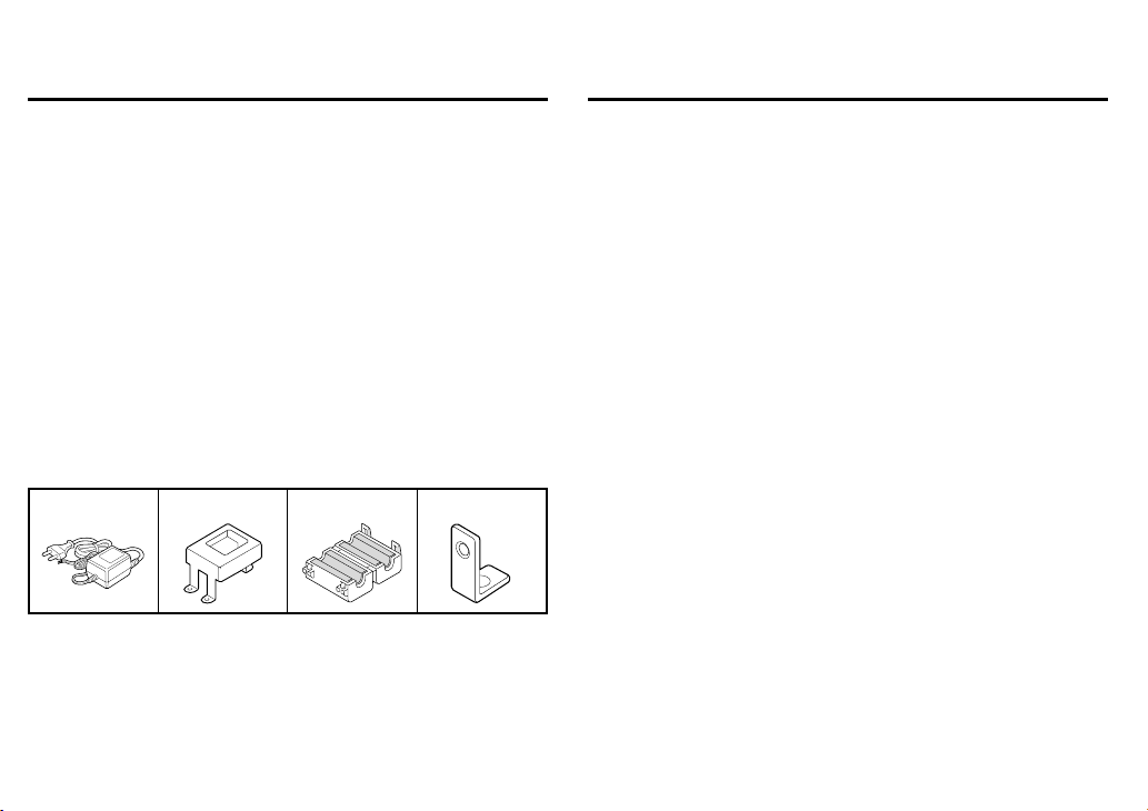
Accessories
1 AC adaptor .............................................................................. 1 pc.
2 AC adaptor mounting plate ..................................................... 1 pc.
: With 3 fixing screws
3 Clamping core.......................................................................... 1 pc.
4 Vertical holder plate................................................................. 1 pc.
1234
• Built-in interline transfer method 1/3" CCD, approx. 320,000
picture elements
• Low smear, anti-blooming, low lag, no burning and no geometric
distortion using the CCD solid state image device
• Built-in fixed focal lens, F=2.0, f=3.8 mm
• 100% solid state components giving excellent immunity to shock
and vibration
• Not subject to interference from magnetic or electrostatic fields
• Built-in IR. LED by very required mininum illumination is approx.
0 lux at 4.5 m
• Horizontal resolution, more than 400 TV lines
• Power supply: 12 V DC operation
English 1
Page 3

PRECAUTIONS
In case of problem
Do not use the camera if smoke or a strange odour comes from the
unit, or if it seems not to function correctly. Disconnect the power
cord immediately, and consult your dealer (or a Sanyo Authorized
Service Centre).
Do not open or modify
Do not open the cabinet, as it may be dangerous and cause damage
to the unit. For internal settings and repairs, consult your dealer (or a
Sanyo Authorized Service Centre).
Do not put objects inside the unit
Make sure that no metal objects or flammable substance get inside
the camera. If used with a foreign object inside, it could cause a fire,
short-circuits or damages.
If water or a liquid gets inside the camera, disconnect the power cord
immediately, and consult your dealer (or a Sanyo Authorized Service
Centre). Be careful to protect the camera from rain, sea water, etc.
Be careful when handling the unit
To prevent damages, do not drop the camera or subject it to strong
shock or vibration.
Install away from electric or magnetic fields
If installed close to a TV, radio transmitter, magnet, electric motor,
transformer, audio speakers the magnetic field they generate will
distort the image.
Protect from humidity and dust
To prevent damages to the camera, do not install it where there is
greasy smoke or steam, where the dampness may get too high, or
where there is a lot of dust.
Protect from high temperatures
Do not install close to stoves, or other heat generating devices, such
as spotlights, etc., or where it could be subject to direct sunlight, as
that could cause deformation, discoloration or other damages.
Be careful when installing close to the ceiling, in a kitchen or boiler
room, as the temperature may raise to high levels.
Install where the temperature range will stay between –10˚C and
50˚C. (no condensation)
Cleaning
• Dirt can be removed from the cabinet by wiping it with a soft
cloth. To remove stains, wipe with a soft cloth moistened with a
soft detergent solution and wrung dry, then wipe dry with dry soft
cloth.
• Do not use benzine, thinner or other chemical product on the
cabinet, as that may cause deformation and paint peeling. Before
using a chemical cloth, make sure to read all accompanying
instructions. Make sure that no plastic or rubber material comes in
contact with the cabinet for a long period of time, as that may
cause damage or paint peeling.
ENGLISH
2 English
Page 4
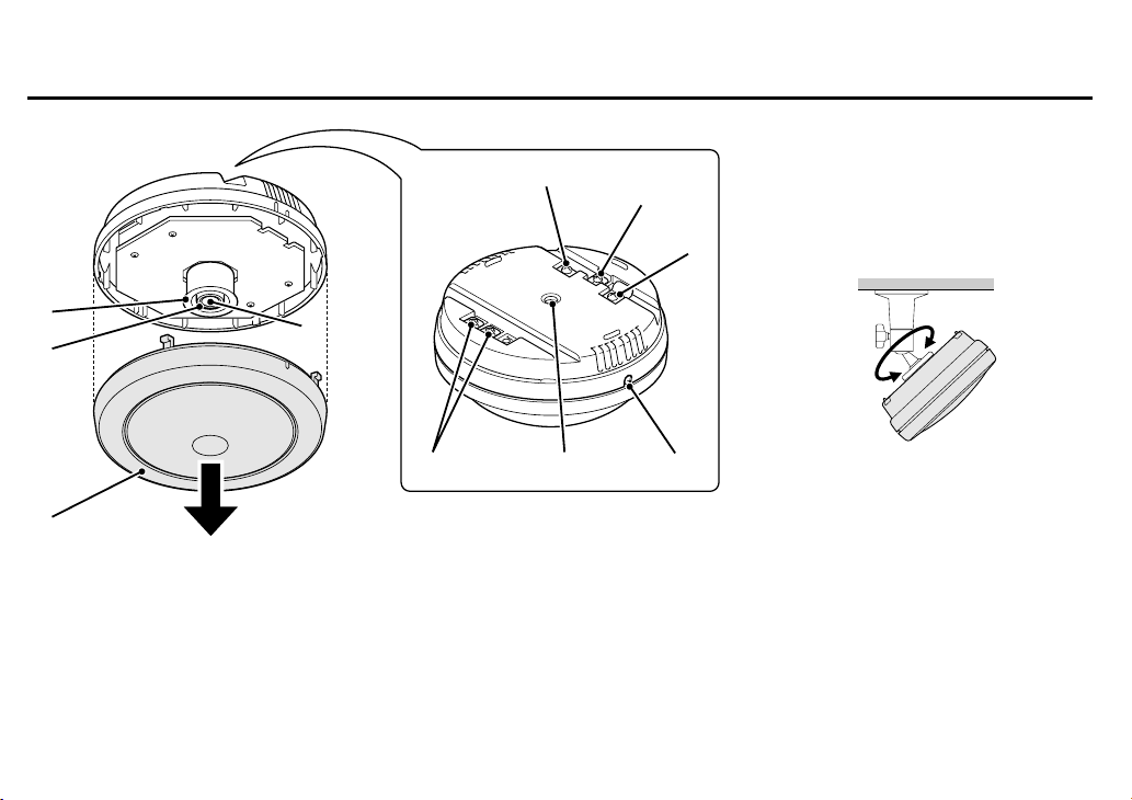
PARTS NAMES AND FUNCTIONS
8
9
8
The view angle of this camera is as follows:
Horizontal: 71˚
Vertical: 53˚
Diagonal: 90˚
To adjust the camera angle, use the camera
mounting bracket (sold separately).
1
2
4
English 3
3
567
Page 5

PARTS NAMES AND FUNCTIONS
1 Hood lens
2 Focus ring
The focus does not need adjustment for subjects 1 m and more
from the lens. If the subject is closer than 1 m, turn the focus ring
to adjust the focus as necessary. (See page 8.)
3 Lens
4 Lens cover
This cover will protect the lens from dust and damage.
5 12 V DC input terminal (12 V DC IN)
Connect DC connecting cord from the AC adaptor to the 12V DC
IN terminal on the base. Then, plug the AC adaptor into an AC
outlet.
WARNING:
• This AC adaptor is specially conceived for this camera. Never use
another type of AC adaptor with this camera, and do not use this
AC adaptor to power other types of cameras.
• Not for use with toys.
• Never try to disassemble or modify the AC adaptor.
6 Camera mounting screw hole (1/4"–20 UNC)
When mounting the camera to the mounting bracket, use this
installation hole.
7 Lens cover fixing screw
8 GND (ground) terminal screw
Loosen the GND terminal screw, insert the coaxial cable into the
clamp and tighten the GND terminal screw.
9 VIDEO OUT terminal screw
Align the centre wire of the coaxial cable with the VIDEO OUT
terminal, then first tighten the cable clamp and then the VIDEO
OUT terminal screw.
• Cable type RG-6U (5C-2V)
4 English
Page 6

CONNECTIONS AND INSTALLATION
Connecting the coaxial cable horizontally
1 Cut and prepare the extremity of the coaxial cable (sold separately), as illustrated.
2 Attach the coaxial cable to the base.
Loosen the VIDEO OUT terminal screw (A) and the GND terminal screw (B), then insert the
center wire of the coaxial cable in the VIDEO OUT terminal and make sure the shielding
mesh part of the cable is located into the GND cable clamper, then tighten both screws (A
and B) to attach the cable.
1
1
Connecting the coaxial cable vertically (using the vertical holder
plate)
1 Cut and prepare the extremity of the coaxial cable (sold separately), as illustrated.
2 Loosen the VIDEO OUT terminal screw and remove the GND terminal screw.
3 Insert the coaxial cable into the GND terminal clamp (a), then attach the clamp to
the supplied vertical holder plate (b) using the screw (c) from the second GND
terminal.
4 Attach the vertical holder plate to the GND terminal using the terminal screw, then
insert the centre wire of the coaxial cable into the VIDEO OUT terminal and tighten
the terminal screw.
English 5
(Return the shielding mesh here)
A
2
B
c
a
b
Page 7

CONNECTIONS AND INSTALLATION
Installing the BNC plug (sold separately)
To connect the camera to peripheral devices, use a coaxial cable with BNC plug.
1 Cut the extremity of the coaxial cable (sold separately), as illustrated.
• Cable type RG-6U (5C-2V), 500 m maximum.
If the type of peripheral devices connected, the type of cable used and/or the cable
length are not as specified, the image and synchronization signals may not be
transmitted correctly.
CAUTION:
Use CCTV/Video grade coaxial cable. Due to its construction, an RG-59U cable will not
transmit the signal properly when installed through conduits or through the air, and
therefore cannot be used.
2 Insert the cable through the adaptor, then turn the shielding mesh over.
3 Loosen the center wire securing screw of the plug, then install the cable in the BNC
plug, so that the center wire is threaded through the plug center opening.
Before tightening the center wire securing screw, make sure the center wire comes out
through the plug center opening.
4 Screw the adaptor onto the plug.
1 2
7mm 8mm
3 4
6 English
Page 8

CONNECTIONS AND INSTALLATION
Basic connections for monitoring or recording
The peripheral devices (VCR, monitor, etc.) and cables are sold separately.
1 Make the video signal connection between the camera and the monitor or time
lapse VCR.
2 Plug the AC adaptor to a wall outlet.
Adjust the picture on the monitor using the Brightness and Contrast controls.
Fig. 2
VIDEO IN
Time lapse VCR
(sold separately)
VIDEO OUT
Multiple cameras connection
You can use multiple cameras by connecting them a camera switcher or a quad unit (sold
separately), then conducting the surveillance from one location by splitting the monitor screen to
view the image from each camera, or by switching the image from each camera on the monitor
screen. For detailed information, please refer to the installed devices instruction manuals.
Fig. 1
VIDEO IN
Monitor
(sold separately)
(Example of connection to a monitor)
VIDEO IN
: VIDEO IN
: VIDEO OUT
CAUTION:
• Make sure the AC adaptor is not
connected to the wall outlet before
connecting it to the 12 V DC input
terminals.
• When making the connections be careful
to respect the polarity and not to
shortcut the terminals.
• When using this unit, the supplied
clamping core must be installed on the
power cord (see Fig. 1), in order to
prevent electromagnetic interference to
the other devices connected.
English 7
Page 9

SETTINGS AND ADJUSTMENTS
Adjusting the focus
1 Loosen the lens cover fixing screw (A).
2 Turn the cover counterclockwise to align the tab (C) on
the lens cover with the tab (B) on the base and remove
the cover.
3 Remove the hood lens (D), then while watching the
image on the monitor turn the focus ring (E) to adjust
the focus.
4 When finished, install the hood lens, then align the tab
(C) on the lens cover with the tab (B) on the base and
turn the cover clockwise until the tab (F) on the cover is
aligned with the tab (B) on the base. Tighten the lens
cover fixing screw (A).
A
E
B
D
C
F
C
8 English
Page 10

TROUBLESHOOTING
SPECIFICATIONS
Before taking the camera for repairs, please check below to make
sure that the camera is used correctly. If it still does not perform
correctly, please consult your dealer or a Sanyo Authorized Service
Center.
No picture on the monitor screen
• Is the power turned on to all connected devices? Is the voltage
correct?
• Are all the signal connecting cables correctly connected?
• Is the lighting sufficient?
The picture is not clear
• Is the monitor correctly adjusted?
• Is the lens focus correctly adjusted?
• Are the lens surfaces clean?
If there is dust or finger prints on the lens, the image quality will
deteriorate. To clean the lens use a soft cloth or a commercially
available lens cleaning set.
SERVICE:
This camera is a precision instruments and, if treated with care, it
will provide years of satisfactory performance. However, in the
event of a problem, the owner is advised not to attempt to make
repairs or open the cabinet. Servicing should always be referred to
your dealer or Sanyo Authorized Service Center.
Camera
TV system CCIR standard (625 TV lines, 25
Scanning system 625 TV lines, 50 field/sec.,
Image device Interline transfer method, 1/3 inch
Picture elements 537 (H) × 597 (V)
Effective picture elements 500 (H) × 582 (V)
Synchronization system Internal sync.
Resolution 400 TV lines horizontally, 400 TV
Video output signal level 1.0 Vp-p/75Ω (screw-on terminal)
S/N ratio More than 50 dB
Minimum required
illumination
Electronic iris range 1/50 to 1/80,000 sec.
Iris system Electronic iris
Gain control Automatic
Lens Built-in, F2.0, f=3.8 mm, fixed focal
Angle of view Horizontally: Approx. 71˚
frames/sec.)
2:1 interlace
solid state CCD
lines vertically
0 lux
lens, focus adjustment
Vertically: Approx. 53˚
Diagonal: Approx. 90˚
English 9
Page 11

SPECIFICATIONS
Operational environmental
conditions
Storage environmental
conditions
Power supply 12 V DC (supplied from AC adaptor)
Power consumption 12 V DC/150 mA
Weight Approx. 160 g
Temperature: –10˚C ∼ +50˚C
Humidity: less than 90% RH
Temperature: –20˚C ∼ +60˚C
Humidity: less than 70% RH
AC Adaptor
Environmental conditions Temperature: –10˚C ∼ +50˚C
Power requirement 220-230 V AC 50 Hz
Power consumption Approx. 3.4 W
Weight Approx. 430 g
Features and specifications are subject to change without prior notice
or obligations.
Humidity: less than 90%
DIMENSIONS
(Camera)
51 mm
(AC Adaptor)
Approx. 1.8 m
75 mm
φ104 mm
50 mm
Approx. 1.8 m
55 mm
10 English
 Loading...