

Page 1
INSTRUCTION MANUAL
BEDIENUNGSANLEITUNG
MANUEL D’INSTRUCTIONS
B/W CCD Camera
CCD-Schwarzweißkamera
Caméra CCD Noir et Blanc
VCB-9112P
About this manual
Before installing and using the camera, please read this
manual carefully. Be sure to keep it handy for later reference.
À propos de ce manuel
Avant d’installer et d’utiliser la caméra, veuillez lire ce
manuel attentivement. Gardez-le à portée de main
pour toute référence ultérieure.
Über diese Bedienungsanleitung
Lesen Sie bitte vor der Montage und dem
Inbetriebnehmen der Kamera zuerst diese
Bedienungsanleitung sorgfältig durch und bewahren Sie
sie zum späteren Nachschlagen auf.
Page 2
CONTENTS
FEATURES
PRECAUTIONS........................................................................................ 2
PARTS NAMES AND FUNCTIONS.......................................................... 3
PREPARATIONS AND CONNECTIONS................................................... 6
CONNECTIONS AND INSTALLATION.................................................... 7
SETTINGS AND ADJUSTMENTS ...........................................................10
INFRARED (IR LED) ILLUMINATION RANGE........................................ 13
TROUBLESHOOTING..............................................................................14
SPECIFICATIONS.....................................................................................15
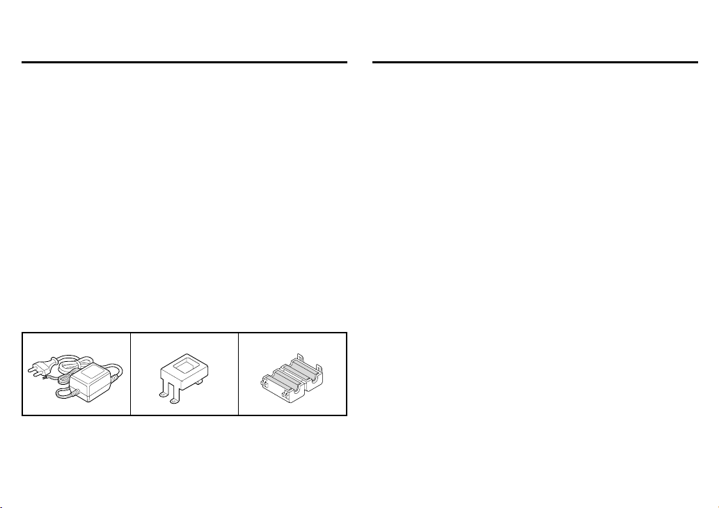
Accessories
1 AC adaptor.............................................................................. 1 pc.
2 AC adaptor mounting plate..................................................... 1 pc.
: With 3 fixing screws
3 Clamping core ......................................................................... 2 pc.
123
Screws for base installation ..................................................... 4 pc.
4
(4 x 35 tapping screws)
The rated value label is located on the back of the camera.
English 1
• Built-in interline transfer method 1/3" CCD, approx. 320,000
picture elements
• Low smear, anti-blooming, low lag, no burning and no geometric
distortion using the CCD solid state image device
• Built-in Vari Focal type auto iris lens, F=2.0 - 2.7, f=2,6 - 5.6 mm
• 100% solid state components giving excellent immunity to shock
and vibration
• Not subject to interference from magnetic or electrostatic fields
• Built-in IR. LED by very required mininum illumination is approx.
0 lux at 4.5 m
• Horizontal resolution, more than 400 TV lines
• With manual PAN/TILT/ROUND mechanism
• Power supply: 12 V DC operation
Page 3

PRECAUTIONS
In case of problem
Do not use the camera if smoke or a strange odour comes from the
unit, or if it seems not to function correctly. Disconnect the power
cord immediately, and consult your dealer (or a Sanyo Authorized
Service Centre).
Do not open or modify
Do not open the cabinet, as it may be dangerous and cause damage
to the unit. For internal settings and repairs, consult your dealer (or a
Sanyo Authorized Service Centre).
Do not put objects inside the unit
Make sure that no metal objects or flammable substance get inside
the camera. If used with a foreign object inside, it could cause a fire,
short-circuits or damages.
If water or a liquid gets inside the camera, disconnect the power cord
immediately, and consult your dealer (or a Sanyo Authorized Service
Centre). Be careful to protect the camera from rain, sea water, etc.
Be careful when handling the unit
To prevent damages, do not drop the camera or subject it to strong
shock or vibration.
Install away from electric or magnetic fields
If installed close to a TV, radio transmitter, magnet, electric motor,
transformer, audio speakers the magnetic field they generate will
distort the image.
Protect from humidity and dust
To prevent damages to the camera, do not install it where there is
greasy smoke or steam, where the dampness may get too high, or
where there is a lot of dust.
Protect from high temperatures
Do not install close to stoves, or other heat generating devices, such
as spotlights, etc., or where it could be subject to direct sunlight, as
that could cause deformation, discoloration or other damages.
Be careful when installing close to the ceiling, in a kitchen or boiler
room, as the temperature may raise to high levels.
Install where the temperature range will stay between –10˚C and
50˚C. (no condensation)
Cleaning
• Dirt can be removed from the cabinet by wiping it with a soft
cloth. To remove stains, wipe with a soft cloth moistened with a
soft detergent solution and wrung dry, then wipe dry with dry soft
cloth.
• Do not use benzine, thinner or other chemical product on the
cabinet, as that may cause deformation and paint peeling. Before
using a chemical cloth, make sure to read all accompanying
instructions. Make sure that no plastic or rubber material comes in
contact with the cabinet for a long period of time, as that may
cause damage or paint peeling.
ENGLISH
2 English
Page 4
PARTS NAMES AND FUNCTIONS
4
3
5
1
1
2
A
F
G
H IJK
1
2
1
6
9
8
7
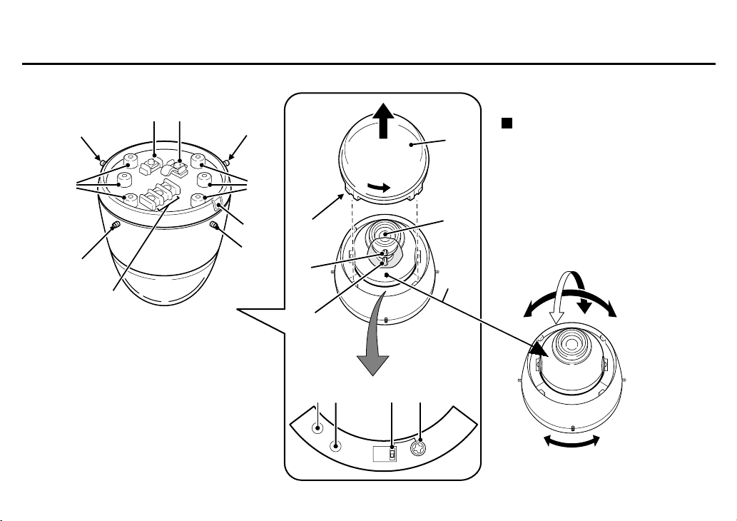
Manual pan, tilt and rotation
The angle of the lens can be adjusted
manually in ranges indicated below.
A: Horizontally ±45˚
B: Vertically ±60˚
C: Rotation of the camera unit ±35˚
B
A
English 3
GND
MONITOR
C
1
2
L
E
V
E
L
BLC
Page 5

PARTS NAMES AND FUNCTIONS
1 Camera unit fixing screws (4)
These screws are used to attach the camera unit to the base.
Tighten the four screws evenly when attaching the camera unit.
2 Screw openings for base installation
These openings are to attach the base to the ceiling or a wall
using the four supplied tapping screws.
3 CAMERA (VIDEO) OUT terminal screw
Video signal output terminal. Insert the center wire of the coaxial
cable into the CAMERA OUT terminal, then tighten the screw to
secure it.
4 GND (ground) terminal screw
Video signal ground terminal. Insert the shielding mesh of the
coaxial cable under the GND terminal plate, then tighten the
screw to secure it.
5 Cabling tab
When the cables cannot be run behind the ceiling, etc., remove
this tab to allow the coaxial cable to go through.
6 12 V DC input terminal (12 V DC IN)
Connect DC connecting cord from the AC adaptor to the 12V DC
IN terminal on the base. Then, plug the AC adaptor into an AC
outlet.
WARNING:
• This AC adaptor is specially conceived for this camera. Never use
another type of AC adaptor with this camera, and do not use this
AC adaptor to power other types of cameras.
• Not for use with toys.
• Never try to disassemble or modify the AC adaptor.
7 Lens cover
This cover will protect the lens from dust and damage. Turn the
cover in the direction of the arrow, shown on the illustration, to
remove it. To install the cover, align the tabs (A) with the
openings, then turn it in the opposite direction.
8 Secondary lens cover
9 Lens
F Focus ring
To set the focus, loosen the focus ring knob, then turn the ring
towards ∞ (infinity) or N (near) as necessary. When the focus is
set as desired, tighten the focus ring knob.
4 English
Page 6

PARTS NAMES AND FUNCTIONS
G Zoom ring
To adjust the viewing range (zoom), loosen the zoom ring knob,
then turn the ring towards T (the range will be smaller and the
subject larger) or W (the range will be wider and the subject
smaller) as necessary. When the zoom is set as desired, tighten
the zoom ring knob.
H GND (ground) pin
For monitor use. (See I)
I MONITOR output pin
When setting up the camera, connect a monitor to this video
output pin and to the GND pin using alligator clip cables, then
using the image displayed on the monitor, set the surveillance
angle and range, the lens focus, etc.
J BLC (backlight compensation) switch
0: Backlight compensation off
1: Backlight compensation on
For backlight compensation, set the BLC switch to 1, then, if
necessary, adjust the LEVEL volume control.
K LEVEL volume control
Used when the BLC switch is set to 1. Under normal conditions, it
should be turned all the way to the left. When adjusting the
backlight compensation, turn it to the right until the desired
correction level is obtained.
English 5
Page 7

PREPARATIONS AND CONNECTIONS
Concerning the coaxial cable
To connect the camera to peripheral devices, use a coaxial cable with BNC plug.
• Cable type RG-6U (5C-2V), 500 m maximum.
• Cable type RG-11U (7C-2V), 600 m maximum.
If the type of peripheral devices connected, the type of cable used and/or the cable length
are not as specified, the image and synchronization signals may not be transmitted
correctly.
CAUTION:
Use CCTV/Video grade coaxial cable. Due to its construction, an RG-59U cable will not
transmit the signal properly when installed through conduits or through the air, and
therefore cannot be used.
Installing the BNC plug (sold separately)
1 Cut the extremity of the coaxial cable (sold separately), as illustrated.
2 Insert the cable through the adaptor, then turn the shielding mesh over.
3 Loosen the center wire securing screw of the plug, then install the cable in the BNC
plug, so that the center wire is threaded through the plug center opening.
Before tightening the center wire securing screw, make sure the center wire comes out
through the plug center opening.
4 Screw the adaptor onto the plug.
1 2
7mm 8mm
3 4
6 English
Page 8

CONNECTIONS AND INSTALLATION
Basic connections for monitoring or recording
The peripheral devices (VCR, monitor, etc.) and cables are sold separately.
1 Make the video signal connection between the camera and the monitor or time lapse
VCR.
2 Plug the AC adaptor to a wall outlet.
Adjust the picture on the monitor using the Brightness and Contrast controls.
Fig. 2
VIDEO IN
Time lapse VCR
(sold separately)
VIDEO OUT
Multiple cameras connection
You can use multiple cameras by connecting them a camera switcher or a quad unit (sold
separately), then conducting the surveillance from one location by splitting the monitor screen to
view the image from each camera, or by switching the image from each camera on the monitor
screen. For detailed information, please refer to the installed devices instruction manuals.
Fig. 1
–
+
VIDEO IN
Monitor
(sold separately)
(Example of connection to a monitor)
VIDEO IN
: VIDEO IN
: VIDEO OUT
CAUTION:
• Make sure the AC adaptor is not
connected to the wall outlet before
connecting it to the 12 V DC input
terminals.
• When making the connections be careful
to respect the polarity and not to
shortcut the terminals.
• When using this unit, the supplied
clamping cores must be installed on the
power cord (see Fig. 1) and on the
signal cable (see Fig. 2), in order to
prevent electromagnetic interference to
the other devices connected.
English 7
Page 9

CONNECTIONS AND INSTALLATION
Coaxial cable connection
1 Cut and prepare the extremity of the coaxial cable (sold separately), as illustrated.
2 Attach the coaxial cable to the base.
Loosen the CAMERA (VIDEO) OUT terminal screw (A) and the GND terminal screw (B), then
insert the center wire of the coaxial cable in the CAMERA (VIDEO) OUT terminal and make
sure the shielding mesh part of the cable is located under the GND terminal plate, then
tighten both screws (A and B) to attach the cable.
CAUTION:
If the base is installed on a wall or if for any other reason the cable cannot be run behind
the installation surface, break-off the tab (C) with nippers to allow the cable to go through.
Camera installation
1 Install the base on the ceiling, etc., using the four supplied tapping screws (A).
• This camera is not waterproof. It cannot be installed outside.
• When installing the base, make sure to verify that the installation surface will allow full
tightening of the screws. Plaster board, etc., may not give a strong enough installation,
and it is recommended to use a reinforcement, or other method so that the screws are
anchored securely.
CAUTION:
When installing the base on a wall, make sure to align it as indicated in Fig. 1.
27mm 14 10mm3
1
(Cut the shielding mesh here)
A
2
B
C
A
( )
Fig 1.
()
8 English
Page 10

CONNECTIONS AND INSTALLATION
2 Install the camera unit onto the base.
Connect the video signal cable plug (B) and the power supply cable plug (C) from the base
to their respective connectors on the camera unit. Then install the camera unit onto the
base.
3 Securely tighten the four camera unit fixing screws (D) evenly.
Camera removal
1 Loosen the four camera unit fixing screws (A) evenly.
2 Turn the camera unit of about 80˚, in the direction of the arrow shown on the
illustration.
Turn the camera unit all the way until screw (B) on the base reaches the tab.
3 Remove the camera unit.
To remove the camera unit, carefully apply a slight force until the screw (B) goes over the
tab, then carefully remove the camera unit.
CAUTION:
• When removing the camera unit, be careful not to hurt yourself with the camera unit
fixing screws.
• When removing the camera unit, be careful as the video signal plug (B) or power supply
plug (C) cables are short and may become unplugged.
B
A
A
C
A
A
B
B
English 9
Page 11

SETTINGS AND ADJUSTMENTS
Factory settings
The camera is shipped from the factory with the following settings. These settings should give
adequate results under normal conditions. If the settings need to be modified, please consult
the reseller or installer.
A: BLC (backlight compensation) switch . . . . . . . . . . . . . . . . . . . . . . . . . . . . . . . 0 (OFF)
B: LEVEL volume control . . . . . . . . . . . . . . . . . . . . . . . . . . . . . . .All the way to the left
Backlight compensation setting
When the subject is backlight, set the BLC switch to 1 (ON).
The backlight compensation will measure the light in the center area of the image and the lens
iris will be automatically set for optimum image quality. The subject contained in this area will
be clear and bright.
• When the sides of the subject background are very bright, and the subject itself is dark.
GND
MONITOR
AB
1
0
BLC
BLC
LEVEL
10 English
Page 12

SETTINGS AND ADJUSTMENTS
☞ In this case, the backlight compensation default setting may not give good results. To
obtain a better image, set the BLC switch to 1 (ON), then turn the LEVEL volume control
to the right until the desired correction level is obtained.
LEVEL
English 11
Page 13

SETTINGS AND ADJUSTMENTS
Zoom and focus adjustments
After the camera has been installed, the zoom and focus must be adjusted while viewing on a
monitor the transmitted image.
1 Remove the lens cover, then press on both sides of the secondary lens cover to
remove it.
2 Loosen the zoom ring knob, then turn the ring towards T or W as necessary.
• T (zoom in) side
The range will be smaller and the subject larger.
• W (Zoom out) side
The range will be wider and the subject smaller.
3
Loosen the focus ring knob, then turn the ring towards ∞ (infinity) or N (near) as
necessary.
4 Repeat steps 2 and 3 until the desired image is obtained.
When finished, tighten the zoom ring and the focus ring knobs. Then, install the secondary lens
cover, making sure it snaps in place and install the lens cover.
NOTE:
While making these settings, be very careful not to scratch or damage the lens.
1
2
3
12 English
Page 14

INFRARED (IR LED) ILLUMINATION RANGE
(
)
(
)
Conditions
Room lighting: 0 lux
Reflection rate: 89.9% on subject
Internal lens: at f=2.6mm
Output range
Horizontal filming
range limit
lens
English 13
3m 2m
30˚
1m
20˚
10˚ 10˚
4.5m
1m
2m
3m
4m
5m
1m 2m 3m
50 IRE
30˚
20˚
Horizontal filming
range limit
lens
Page 15

TROUBLESHOOTING
Before taking the camera for repairs, please check below to make sure that the camera is used correctly. If it still does not perform correctly,
please consult your dealer or a Sanyo Authorized Service Center.
No picture on the monitor screen
• Is the power turned on to all connected devices? Is the voltage correct?
• Are all the signal connecting cables correctly connected?
• Is the lighting sufficient?
The picture is not clear
• Is the monitor correctly adjusted?
• Is the lens focus correctly adjusted?
• Are the lens surfaces clean?
If there is dust or finger prints on the lens, the image quality will deteriorate. To clean the lens use a soft cloth or a commercially available lens
cleaning set.
SERVICE:
This camera is a precision instruments and, if treated with care, it will provide years of satisfactory performance. However, in the event of a
problem, the owner is advised not to attempt to make repairs or open the cabinet. Servicing should always be referred to your dealer or Sanyo
Authorized Service Center.
14 English
Page 16

SPECIFICATIONS
Camera
TV system CCIR standard (625 TV lines, 25
Scanning system 625 TV lines, 50 field/sec.,
Image device Interline transfer method, 1/3 inch
Picture elements 537 (H) × 597 (V)
Effective picture elements 500 (H) × 582 (V)
Synchronization system Internal sync.
Resolution 400 TV lines horizontally, 400 TV
Video output signal level 1.0 Vp-p/75Ω (screw-on terminal)
S/N ratio More than 50 dB
Minimum required
illumination
Backlight compensation 1 (ON)/0 (OFF) manual switching,
Backlight compensation iris
level adjustment
Gain control Automatic
MONITOR output pin 1.0 Vp-p/75Ω, test point pin
frames/sec.)
2:1 interlace
solid state CCD
lines vertically
0 lux
center area light measuring system
Manual LEVEL volume control
Lens F2.0 ∼ 2.7, f=2.6 ∼ 5.6 mm,
Iris system Mechanical auto iris
Manual adjustment image
angle range
Operational environmental
conditions
Storage environmental
conditions
Power supply 12 V DC (supplied from AC adaptor)
Power consumption 12 V DC/220 mA
Weight Approx. 430 g
varifocal lens, manual zoom and
focus adjustment
Horizontally (pan): ±45˚,
Vertically (tilt): ± 60˚, Rotation of
the camera unit: ±35˚
Temperature: –10˚C ∼ +50˚C
Humidity: less than 90% RH
Temperature: –20˚C ∼ +60˚C
Humidity: less than 70% RH
AC Adaptor
Environmental conditions Temperature: –10˚C ∼ +50˚C
Power requirement 220-230 V AC 50Hz
Power consumption Approx. 4.5 W
Weight Approx. 440 g
Features and specifications are subject to change without prior notice
or obligations.
Humidity: less than 90%
English 15
Page 17

SPECIFICATION
DIMENSIONS
(Camera) (AC Adaptor)
112mm
11mm
110mm
φ
83.5mm
83.5mm
6-
66.7m
φ
4.3mm
m
Approx. 1.8 m
75
Approx. 1.8 m
50
55
: mm
16 English
 Loading...