

Page 1

- i -
Page 2

Manual
TABLE OF CONTENT
Overview................................................................................................................. 6
Chapter 1................................................................................................................................. 7
Network (IP) Cameras ............................................................................................ 7
Digital Video Recorder........................................................................................... 7
PTZ Cameras .......................................................................................................... 8
USB and Web Cameras .......................................................................................... 8
Frame Grabbers....................................................................................................... 9
Video Pilot Terminology ...................................................................................... 10
Toolbar.................................................................................................................. 10
Structure Pane....................................................................................................... 11
Server.................................................................................................................... 12
Client..................................................................................................................... 13
Web Based Remote............................................................................................... 14
ENTEPRISE SCALABILITY AND MONITORING.......................................... 15
Chapter 2............................................................................................................................... 16
Server Installation................................................................................................. 16
Software Activation.............................................................................................. 17
Install Server Configuration.................................................................................. 17
Server Network Settings and Port settings............................................................ 17
Application Mode. ................................................................................................ 18
Service Mode........................................................................................................ 19
How to stop and start DVR services..................................................................... 20
Client Server Connections .................................................................................... 20
Control Server or Servers from your client application........................................ 21
Chapter 3............................................................................................................................... 22
Server Recording Properties-................................................................................ 22
Server Communication Properties-....................................................................... 23
Server Watchdog Properties ................................................................................. 24
Start Watchdog with Server-................................................................................. 24
Enable Watchdog-................................................................................................. 24
Watchdog Operation............................................................................................. 24
Maintenance-......................................................................................................... 24
Enable Periodic Restart- ....................................................................................... 24
Server User Management- .................................................................................... 25
Create Users or modify existing user rights.......................................................... 25
System/User Permissions- .................................................................................... 26
Submitting A Problem Report-............................................................................. 27
Chapter 4............................................................................................................................... 28
Setting up an IP camera… .................................................................................... 28
IP Servers.............................................................................................................. 28
Configure your IP cameras automatically............................................................. 28
- ii -
Page 3

Configure your IP cameras manually. .................................................................. 28
Access Tab............................................................................................................ 29
Frame Tab............................................................................................................. 29
Setup Arecont Network IP Cameras..................................................................... 30
Setup SANYO standalone DVR........................................................................... 31
Setup SANYO Pan Focus IP camera.................................................................... 32
CCTV Camera Configuration............................................................................... 32
Device Title........................................................................................................... 32
Format Tab- .......................................................................................................... 33
Frame Tab –.......................................................................................................... 33
HiCap & XECAP Tab........................................................................................... 34
PTZ Camera Properties......................................................................................... 34
PTZ Protocols-Communication Settings .............................................................. 35
PTZ Control Pane ................................................................................................. 36
Save Presets, and Tours for PTZ Cameras............................................................ 36
Digital PAN-Tilt-Zoom on live view.................................................................... 37
Digital PAN-Tilt-Zoom on Playback.................................................................... 37
Video Compression............................................................................................... 37
Enable Video Transfer Properties:........................................................................ 38
Image Quality........................................................................................................ 38
Motion Analysis- .................................................................................................. 39
Sensitivity Tab-..................................................................................................... 39
Exclusion Tab-...................................................................................................... 39
Data Recording ..................................................................................................... 40
Time Lapse Recording:......................................................................................... 41
Motion Control Recording:................................................................................... 41
Video Adjustments: .............................................................................................. 42
Toggle Video Amplification Pane........................................................................ 42
Exclusivity Mode (Windows lock out feature):.................................................... 43
Chapter 5 – Sanyo DSR Settings.......................................................................................... 44
Recording Status................................................................................................... 44
Clock Set............................................................................................................... 44
Daylight Saving/Ext Clock set.............................................................................. 44
Holiday Set............................................................................................................ 45
Recording Area Set............................................................................................... 45
Recording Conditions Set..................................................................................... 45
Normal REC Mode Set......................................................................................... 46
Program REC Set.................................................................................................. 46
Timer Set............................................................................................................... 47
Alarm REC Mode Set........................................................................................... 47
Display Set............................................................................................................ 48
Buzzer Set............................................................................................................. 48
HDD Set ................................................................................................................ 48
Network Set .......................................................................................................... 49
RS-485 Set............................................................................................................ 49
Mask Set................................................................................................................ 49
Power Loss/Used Time......................................................................................... 50
Initialization Log................................................................................................... 50
Chapter 6 - Sanyo Network Camera Settings....................................................................... 51
- iii -
Page 4

Camera Settings.................................................................................................... 51
Recording Settings................................................................................................ 51
Clock Settings....................................................................................................... 52
E-Mail Settings ..................................................................................................... 53
Network Settings................................................................................................... 53
Chapter 7............................................................................................................................... 54
How to Playback Video-....................................................................................... 54
Playback Window Structure- ................................................................................ 54
To Navigate through the Video -........................................................................... 54
Fast forward & Rewind......................................................................................... 54
Smart Search-........................................................................................................ 55
Define motion of interest –................................................................................... 55
Export Video-........................................................................................................ 56
Export Snapshots. ................................................................................................. 57
Layouts.................................................................................................................. 58
Layout Sequences ................................................................................................. 59
Chapter 8............................................................................................................................... 60
Upgrading Video Pilot software to a newer Version............................................ 60
Specifications........................................................................................................................ 61
Table of Recording rate and size .......................................................................... 61
Minimum System Requirements........................................................................... 62
- iv -
Page 5

Page 6
Overview
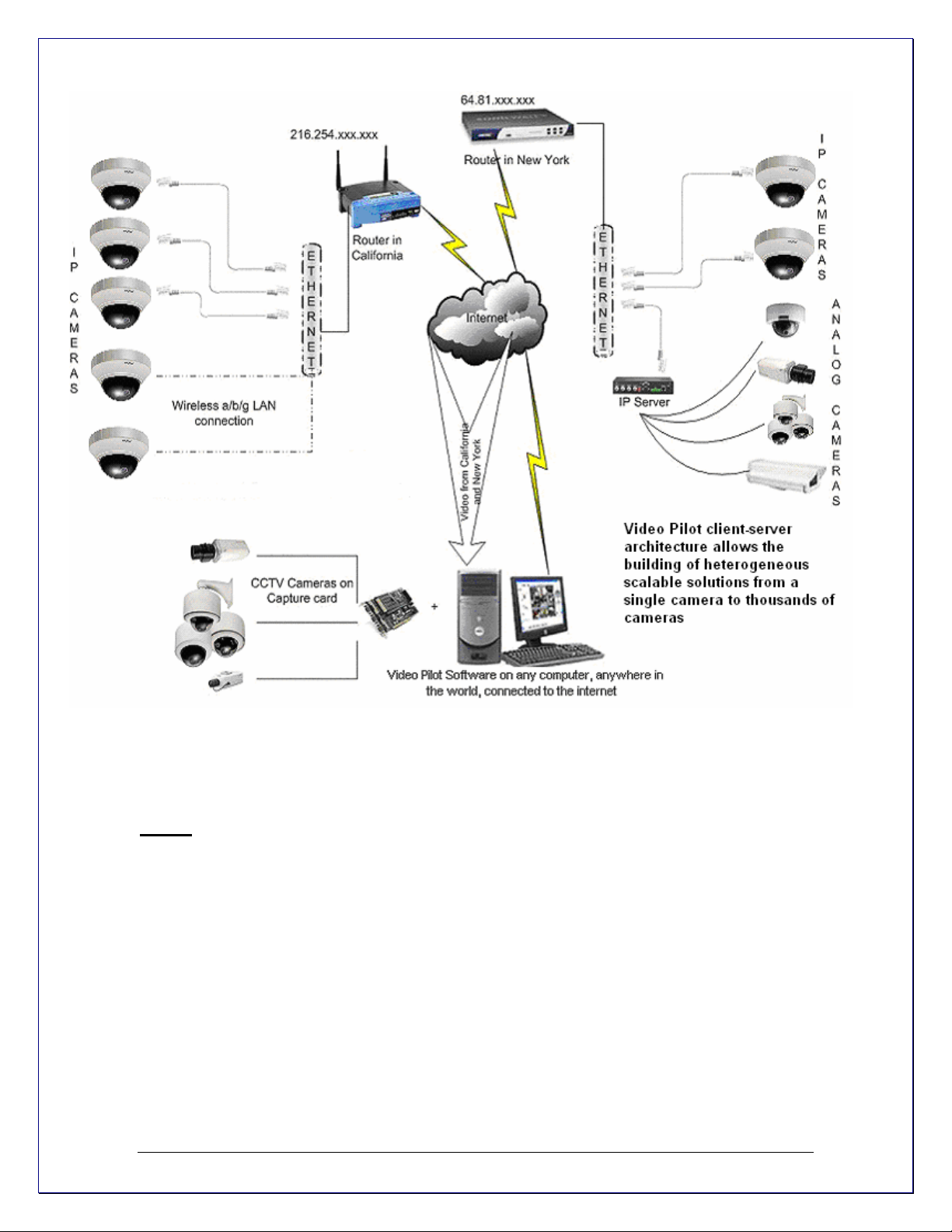
Video Pilot is a digital video recording and remote surveillance software package for Windo ws.
Video Pilot accepts video streams from all major Network (IP) cameras and servers, Frame
Grabbers and any Direct Show compatible devices including Webcams and US B cameras. This
along with the Video Pilot client-server architecture allows you to build fully scalable solution
sizing from a single camera up to thousands of cameras.
Video Pilot was designed to primarily be used to:
1.View live video streams from multiple sources locally and remotely, over the Internet.
2.Record video from multiple sources and play them back later locally or remotely
3.Export previously recorded video to preserve it and to present it as evidence.
Video Pilot offers a principally new concept for DVR solutions – “One Software/Choice of
Hardware”. Video Pilot DVR software can be either integrated with supported hardware or
acquired from a Video Pilot reseller as a part of a complete digital video recording and remote
surveillance solution.
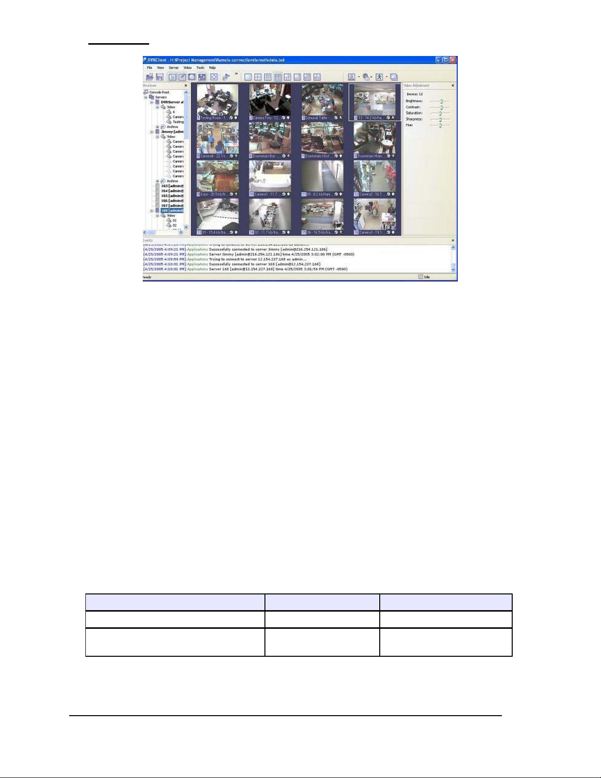
Video Pilot consists of two major components: DVRServer and DVRClient. The DVR Server is a
behind-the-scene application that captures, processes and records video and then serves it to a
local or remote DVR Client software. The DVR Client is the application that shows live and
recorded video streams from a single DVR Server or multiple DVR Servers; it also allows users to
configure and control DVR Server(s).
In order to better suit our customers' needs and budget, Video Pilot has 2 editions. These editions
vary in the number of allowed cameras, the number of simultaneous remote DVR Client
connections as well as other limitations, or lack thereof. However, all of the Video Pilot editions
have the same user-friendly interface and functionality.
Maximum Number of Video Streams 16 Unlimited
Maximum number of concurrent remote
DVR Client connections
- 6 -
Advanced Enterprise
5 Unlimited
Page 7
Chapter 1
Network (IP) Cameras
installation.
Network cameras have built-in motion detectors and compression engines, which enable the
DVR Server to use a minimum of its computer resources; therefore, the same computer can also
be used for other tasks.
There are no requirements on CPU or chipset manufacturers, since Network Cameras do not
require any additional hardware to be installed in to the computer.
There are Network (IP) cameras with very high resolution (1.3 Mega pixels and more). Analog
cameras are incapable of achieving such resolution.
Network (IP) camera installations are highly scaleable and upgradeable. There is no ne ed to buy
and install additional video capture boards for the DVR system in the event you want to add a
camera or increase performance of the system.
Any analog camera can be converted to a network camera by using a Network (IP) server.
There is no geographical limitation for the installation.
Effective offsite recording (either by itself or in addition to onsite recording) eliminates the
possibility of destruction of the video medium due to deliberate actions or an accident (fire,
flooding, etc.).
Some of the network cameras also can be used as a webcam to serve as an advertising engine
for a business.
Video Pilot supports Network Cameras from all major manufacturers. Please visit the
www.sanyocctv.com for the perpetually growing list of supported Network cameras.
Digital Video Recorder
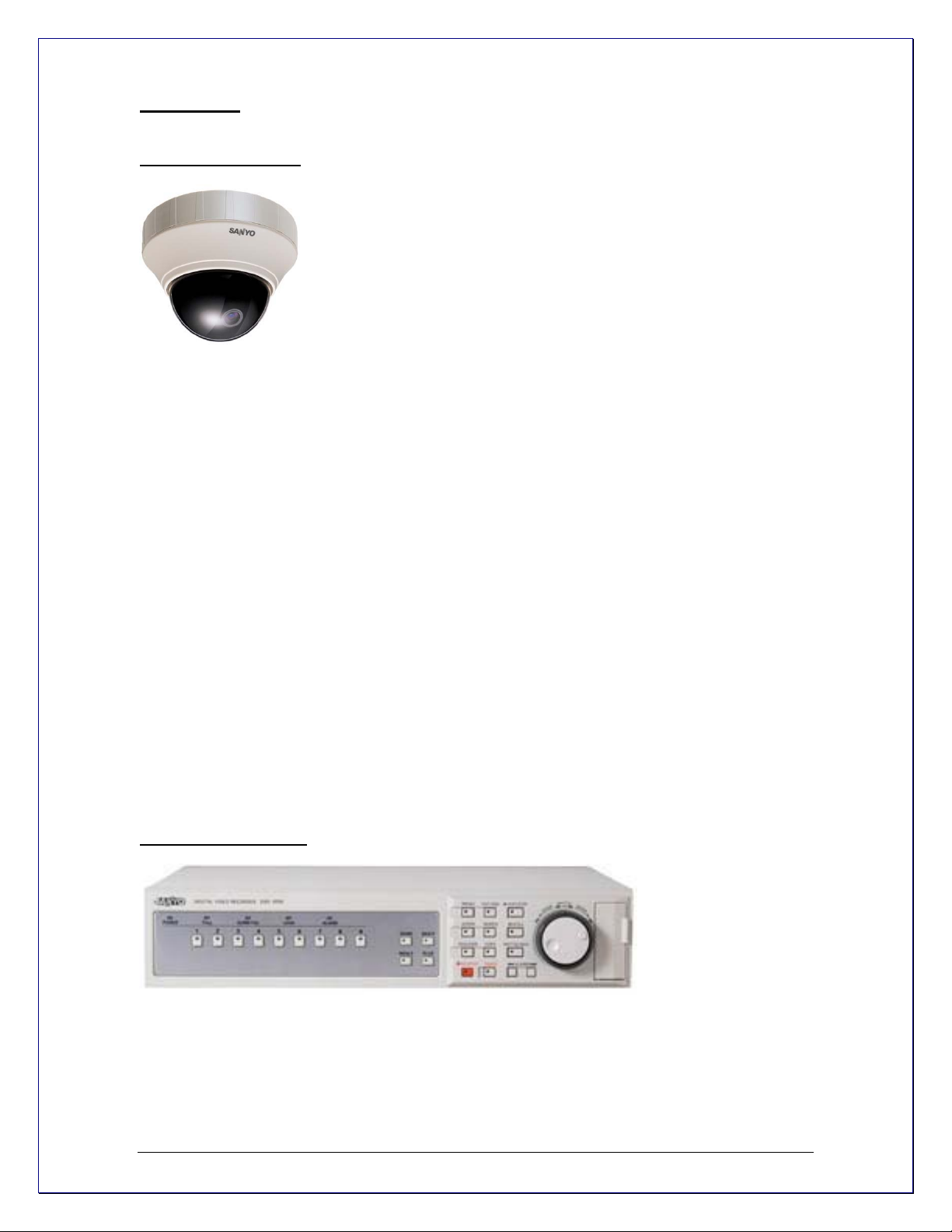
What is Network (IP) Camera? Network camera, IP
addressable camera, IP Camera, all referring to the same type of
cameras, is a digital camera that can be directly connected to the
Internet through a CAT5 or WiFi connection. Network cameras send
already digitized and compressed video streams. Network Cameras are
the fastest growing trend in the Surveillance industry. Here are some of
the benefits of IP cameras:
Existing local network infrastructure could be used for the installation.
Comparably less cabling required compared with an analog CCTV
What is Digital Video Recorder? A DVR (digital video recorder) is a device that allows
you to record video from analog cameras in digital format.
Digital recorders store the digitally encoded video on Hard Drives. The usually include additional
features such as multiplexed analog display outputs, alarm recording, redundant recording o nsite, video search functions for playback, and telemetry control of PTZ cameras.
The Sanyo Digital Recorders that Video Pilot connects to provide the same function as a video
encoder; in that they bridge the gap between Analog cameras and the digital world allowing video
- 7 -
Page 8
images to be transmitted over a network. Additional benefits include remote access to the
telemetry controls, and redundant on-site recording
PTZ Cameras
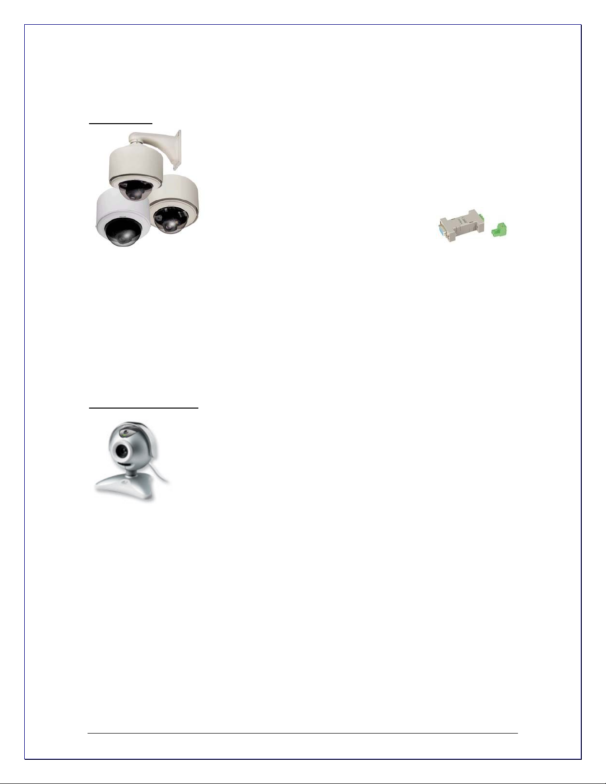
What are PTZ Cameras? PTZ camera is the camera with
the mechanical assembly for Panning, Tilting and Zooming the
camera. There are many types of PTZ cameras available and their
cost varies based on Speed, Zoom capacity, Manufacturer, etc.
Analog CCTV PTZ cameras require additional set of wires compliant
with RS422/485 protocol standard to control
PTZ movements. Therefore, usually it is
necessary to put a RS232 to RS422/485
converter to a DVR system. RS232 to
RS422/485 converter is a small unit that plugs to the serial port on
the back of your computer.
Video Pilot currently supports the most popular Analog CCTV PTZ command protocols, including
Sanyo, Pelco-D, Bosch, Philips and Merit-Lilin. Network PTZ cameras do not require any
additional wiring or devices, since PTZ commands are being sent over a TCP/IP network;
therefore, making the installation process much simpler and eliminating a lot of compatibility and
configuration issues.
In the case of Sanyo PTZ cameras, they can be connected directly to the Sanyo DVR without the
requirement of a converter.
USB and Web Cameras
Can I use my USB or Web Cameras? Yes, Video Pilot is the world’s leader in the best
most economic, versatile and powerful DVR. We want everyone to be able to use our software
and if you have a USB cam or a Web Cam, feel free to try our software for free and purchase as
many licenses as you wish. Of course don’t forget that you are limited to USB ports with this
option but for small users, Video Pilot is for you.
- 8 -
Page 9

Frame Grabbers
What is Frame Grabber? Frame Grabber is a PCI board that is installed into the PC and
CCTV cameras (Cameras with BNC or RCA connectors) are attached thereto. These boards
come in various configurations 4 camera inputs, 8 inputs, 16 inputs, etc. and boards are made by
various manufacturers. Also, depending on the Frame Grabber certain criteria is expected from
the PC. Some frame grabbers require a minimum amount of PC power as where others require
more. Frame Grabbers have the following terminology:
Inputs = The amount of cameras the board can handle (4, 8, 16, 24, 32)
Frame Rate = Frame Grabbers supported by Video Pilot come in 60Frames, 120Frames and
240Frames per second. These frames however, are the entire frame rate numbers divided by the
amount of inputs; therefore if you have a 60FPS (Frame Per Second) board with 4 inputs, that
means 4 divided by 60FPS = 15FPS per camera.
The other important factor in Frame rates is FPS viewing and FPS recording. What this means, is
that you may view at 15FPS but choose to record any of your cameras at a lower FPS to save
storage space. Remember, the higher the FPS the more storage space it needs since the data is
larger. The same principle applies to image quality. The higher the image quality you choose, the
more space is required. More on image quality on page 38
You can purchase these boards from any Video Pilot authorized reseller, or if you currently
purchase or own any of the above cards, you only need to purchase the appropriate Video Pilot
Edition.
Video Pilot works with any and all CCTV cameras. CCTV cameras are analog cameras, even
though some of them might have written the word Digital written on them, which only means that
a DSP chip is used, but the Frame Grabber is what makes the signal truly digital. Therefore, if
you decided to retrofit existing installation or make a new one based on analog CCTV cameras,
make sure that you choose a Video Pilot supported frame grabber card or acquire a complete
system from a Video Pilot reseller. You can check the perpetually growing list of supported
Frame Grabber cards on the Video Pilot website.
- 9 -
Page 10
Video Pilot Terminology
Pane - Panel, window.
Toggle- To alternate between two or more electronic, mechanical, or computer-related options,
usually by the operation of a single switch or keystroke.
Video Pilot Icons-
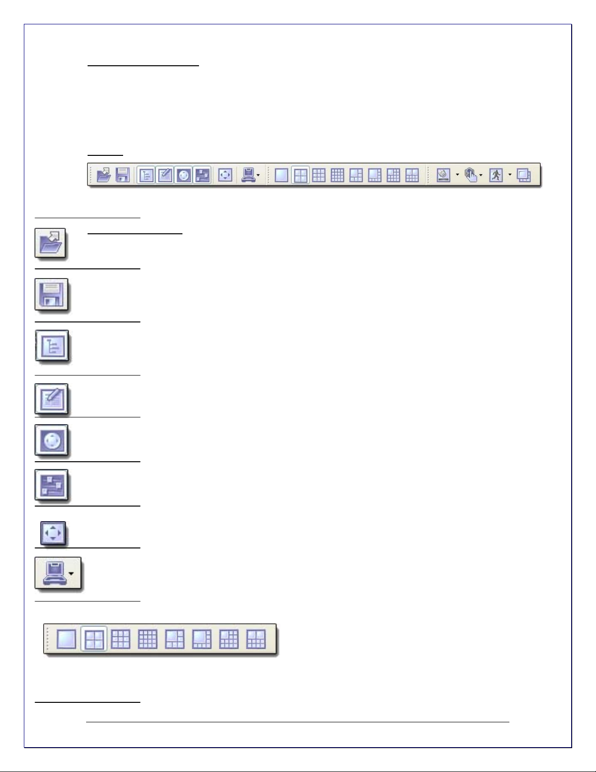
Toolbar
Toolbar- The toolbar that you see at the top of your screen gives you various options such as
open, save and various screen manipulations, at the click of a button.
Open Configuration-
This button on the toolbar allows you to open previous Video Pilot
configurations. It is most useful if you are exporting configurations from one machine to another.
Save Configuration- This button on the toolbar allows you to save any changes that you have
just made to your DVR, it will continue to save to the same file unless you click on File and Save
As then you can save to a different file or even to a floppy.
Structure Pane- This button toggles whether you see or don’t see the structure pane on the left
side of your Video Pilot window. The structure pane is most useful when you are looking at
cameras from multiple locations and multiple Video Pilot servers. We will discuss the structure
pane later on in this chapter.
Events - This button toggles the events window. The events window gives you important
notifications such as, when you are connecting to a server successfully. It lets you know if you
have input improper user names and passwords and gives you error codes when needed.
PTZ Control- This button toggles the PTZ control pane. If you do not have a pan-tilt-zoom
camera connected to your system then this button does no need to be pressed.
Video amplification- This button toggles the video amplification pane. When this button is
pressed a pane will come up from which you will be able to adjust the brightness, contrast,
saturation, sharpness, and hue for any camera.
Full Screen- This button toggles full screen mode. In full screen, none of the panes will be seen
and the cameras will be expanded to their maximum size to fill the full screen of your monitor.
Wizards- The wizard’s icon on the toolbar gives you a shortcut to various serve r, and camera
options and configurations. You can also access these features through the right click menus in
the software.
Views- These buttons on the toolbar allow you to manipulate your views and camera layouts to
your own preference.
- 10 -
Page 11
Screen Footer- The screen footer button on the toolbar allows you to display various information
underneath each camera window. It can display frame rate, time, picture quality, recording,
motion detection, and image size. The screen footer is the text below each camera
Stream Selection- The stream selection button allows you to pick which camera you would like
to view in the selected camera window. This can also be done through the right click menus and
by dragging the desired camera from the structure pane to the desired display window, or right
click on any camera window and select stream.
Show Motion- The show motion toolbar button toggles whether or not you want the motion
outlined on the selected camera screen. Note: Motion detection must be setup before this feature
can be activated.
Maximize- When pressed the maximize button puts the selected camera into a single view, if
pressed again it will return to the previous view. This can also be accomplished by double clicking
on the camera of choice.
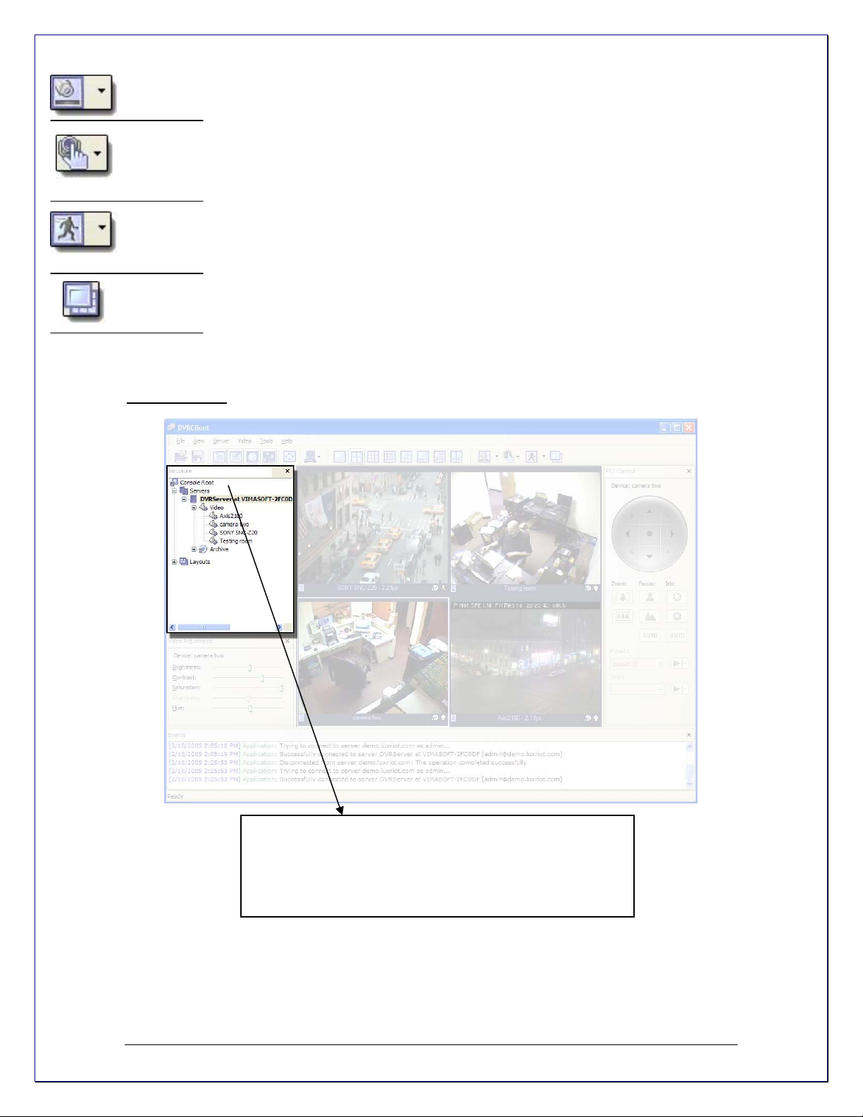
Structure Pane
The structure pane is the control center of your DVR. In the
structure pane is where you will setup all of your cameras,
and DVR’s. The structure pane makes it possible for you to
manage many DVR servers from one window by right click
on the DVR of your choice.
- 11 -
Page 12
Server
What is Video Pilot Server? Video Pilot server is the Windows application, which can
run as Windows service or Windows tray-application. Video Pilot Server grabs video streams
from the configured sources, analyzes it for motion, broadcasts it to local (running on the same
computer) and remote clients and records it to a local hard drives. Video Pilot server is the only
application in the Video Pilot suite, which requires licensing, which can be activated via software
key.
Through Console Root
an unlimited number of
cameras and servers
can be manage,
configured, and
adjusted, without the
need to be at the
server site.
Right mouse click on
any camera or server
to drop down a list of
various options like
camera setup,
recording settings,
user management,
…etc
Right Mouse Click on
any camera screen to
bring up the archive
(playback recorded
Wizards for easy
navigation and stepby-step setup to
perform configurations
and other setup tasks.
- 12 -
Page 13
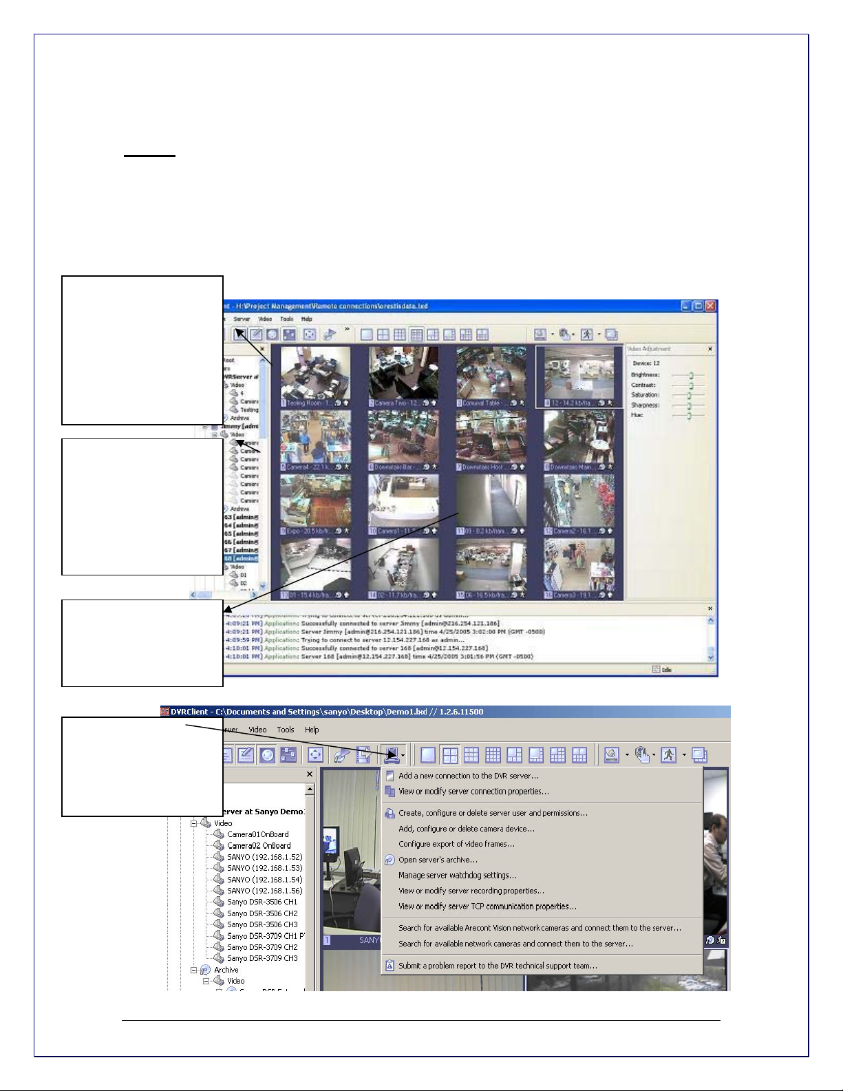
Client
What is Video Pilot Client? Video Pilot Client Application is the component to monitor live and
recorded video from several Video Pilot servers. Also Video Pilot Client is the main tool to
manage and configure local and remote Video Pilot servers.
The Client component is the control interface of your Video Pilot Software is the Interface to
control your Video Pilot surveillance system. The client is the piece of software that controls every
aspect of your server. This software can be installed on the main machine running the server or
on any machine that can access the server via TCP/IP. The client application can be used to
control and fully administer your server or an unlimited number of servers from any computer
connected on the Internet. You never need to go on-site again to make changes to your DVR.
- 13 -
Page 14

Connect to
Multiple
servers,
manage
servers and
cameras
through the
client software
Benefits – By not having to ever be on-site to administer your DVR is a tremendous advantage
and one that VIDEO PILOT offers. We have revolutionized the DVR world with this application
feature enabling full flexibility to the DVR operator. Another advantage to not installing the Client
on the Server Site is your DVR is now Tamper Proof. Since Video Pilot server can run as a
Windows service. The server/Computer running the software can be logged out of Windows and
have login password protected.
Web Based Remote
The Client Application is of course your main remote viewing option giving you full control of your
DVR, all of its recorded video, etc., however; we wanted to give you a web based option as well
incase you are ever in need to check on your location and the client software is not an option. For
these instances, you can log onto your site using our web application located at
http://www.sanyocctv.com
- 14 -
Page 15
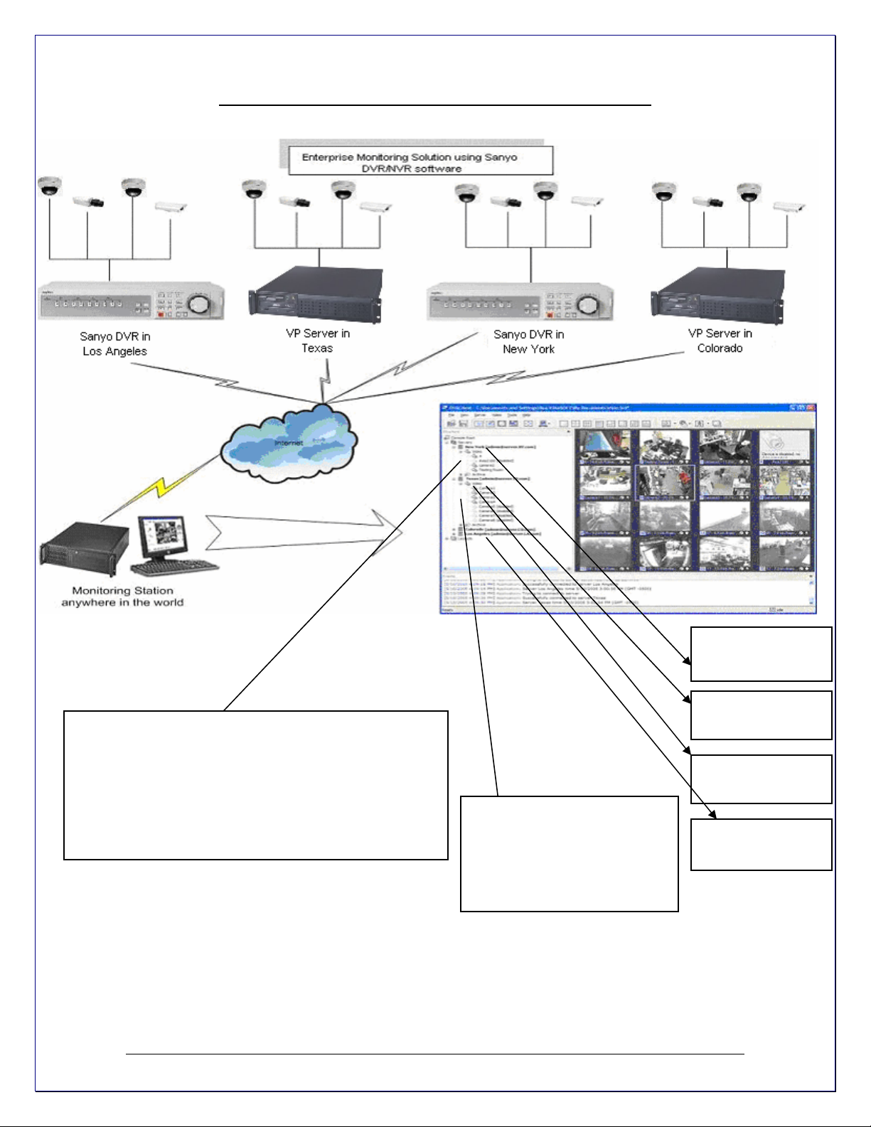
ENTEPRISE SCALABILITY AND MONITORING.
Enterprise Scalability:
Control and fully administer your server or an unlimited
number of servers from any computer connected on the
Internet with Video Pilot client. Engineer not to use any
network resources for the open server connections and
only use network resources for the cameras you monitor
at the given time . Can be connected to unlimited server
and control unlimited cameras within those servers.
Layouts: Create custom
layouts by grouping cameras
from different DVR
Servers/Location into groups
for more efficient monitoring,
and better management.
Sanyo DVR in Los
Angeles
VP Server in
Texas
Sanyo DVR in
New York
VP Server in
Colorado
- 15 -
Page 16
Chapter 2
Server Installation
Lets Begin Installing- Insert your Video Pilot CD into your CD drive, or if you have downloaded
Video Pilot begin the installation process by double clicking the Video Pilot file.
st
Screen- “Welcome to the Video Pilot Digital Video Recorder Setup Wizard”
1
Click next
nd
Screen- “Software License Agreement” Please read and choose accept
2
Click next
rd
Screen- “Release Notes”
3
Click next
th
Screen- “Select installation Destination” changing the location is optional
4
but not recommended.
Click next
th
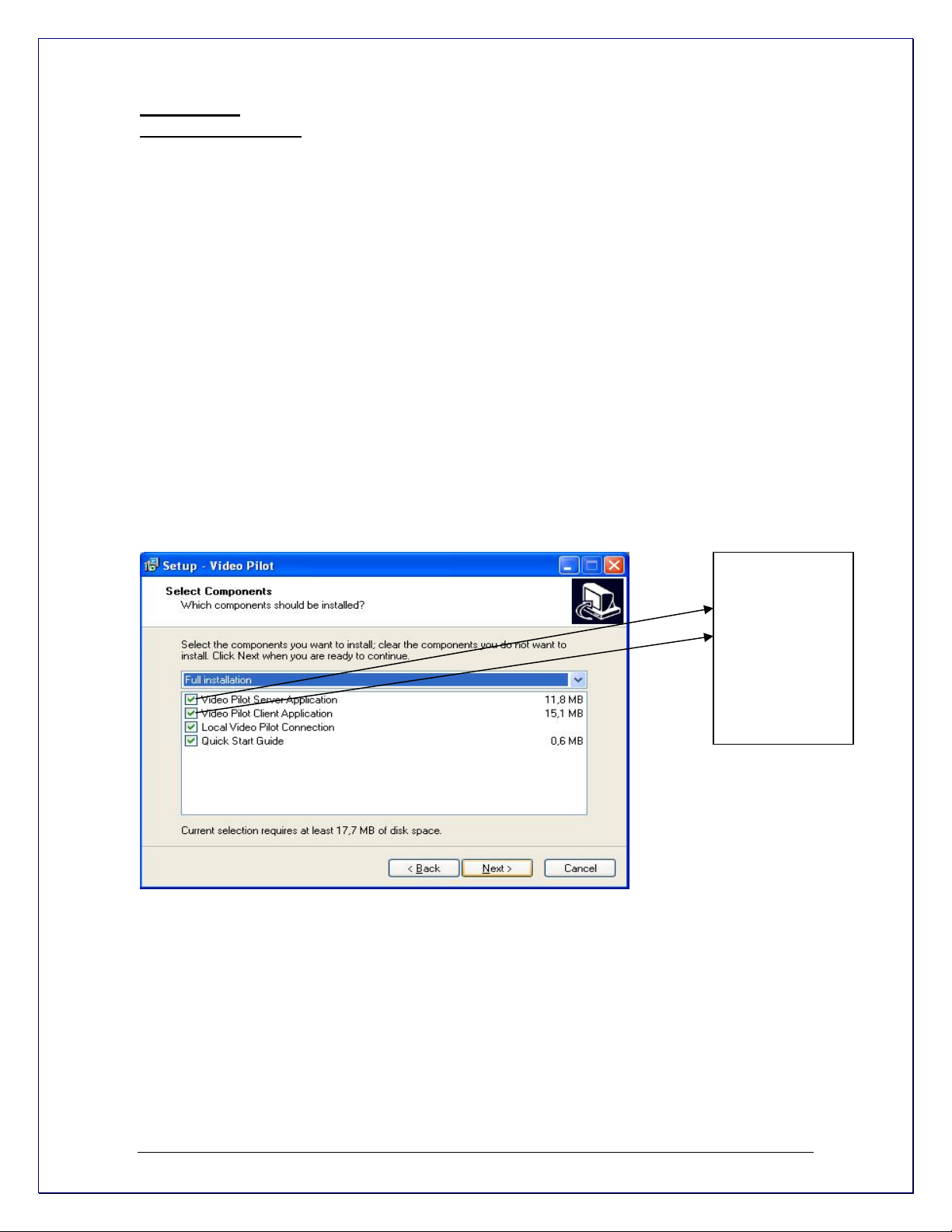
Screen- “Select Components” Here you will need to check the top
5
Unchecked option “VIDEO PILOT SERVER APPLICATION”
This option needs to be checked now, since we are now
Installing The Server portion of the Video Pilot package. If you would
also like to install the GUI (Graphic User Interface) or the CLIENT put
a checkmark next to Video Pilot client application.
Then leave the rest of the boxes unchecked. If you would like to
Have the server run without the client, please uncheck the remaining
Boxes.
If you want to be
able to view and
manage the
server from the
same machine
check both
Video Pilot
Client & Server
Application.
Click next
th
Screen- “Select Start Menu Folder” changing the location is optional
6
But not recommended.
th
Screen- “Additional Icons” These are shortcuts and are recommende d
7
but optional.
Click next
th
Screen- “Ready to Install” Video Pilot Server and options will now be
8
Installed.
Click Install
th
Screen- “Completing the Video Pilot Recorded Setup Wizard” Here there
9
Is an option for “run server setup wizard” Leave it checked
And lets continue. Click Finish
- 16 -
Page 17
Software Activation
1st Screen- “Wizard explanation”
Click Next
nd
Screen- IF YOU HAVE DOWNLOADED VIDEO PILOT THE SHAREWARE
2
VERSION, click cancel and skip down to page eight of your
manual “Install Server Configuration. For those who have
purchased Video Pilot or wish to purchase Video Pilot at this time
Click Next
rd
Screen- “Product Activation Options” If you have purchased a License
3
or would like to make a purchase now, choose option one
Click Next
th
Screen- “Enter your Activation Key” carefully enter your product
4
License key here. (If you are now making the purchase
Choose “buy online” now. Once you have made your purchase
you can come back to this screen at any time)
Click Next
th
Screen- “Product has been successfully activated” you will also see
5
the description of your edition and your access limitations.
Click Finish
Install Server Configuration
st
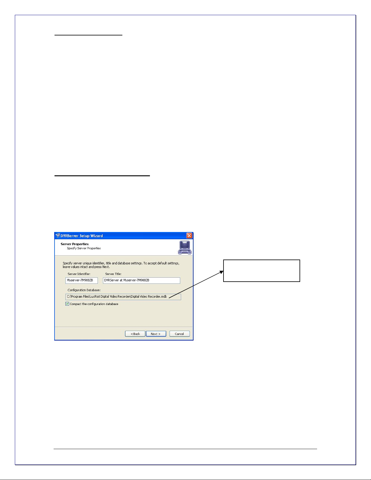
Screen- “Server Properties” Here is where you will enter your Click Next
1
Machines unique Identifying name and server title. Underneath
You will see an option that is by default UNCHECKED
“Compact the configuration database” it is a good choice to check
This option for it will help optimize your configuration database in
The future.
Default Install Directory
of Database
nd
Screen- “Server Administrator Settings” Here you are setting up
2
The settings for the Administrator. Leave the default
User name to “admin” and enter a unique password in
Both lines. You will have the chance to add additional users
At a later time. Click Next
rd
Screen-
3
Server Network Settings and Port settings
The default firewall port that Video Pilot uses is 60554 but you can
- 17 -
Page 18
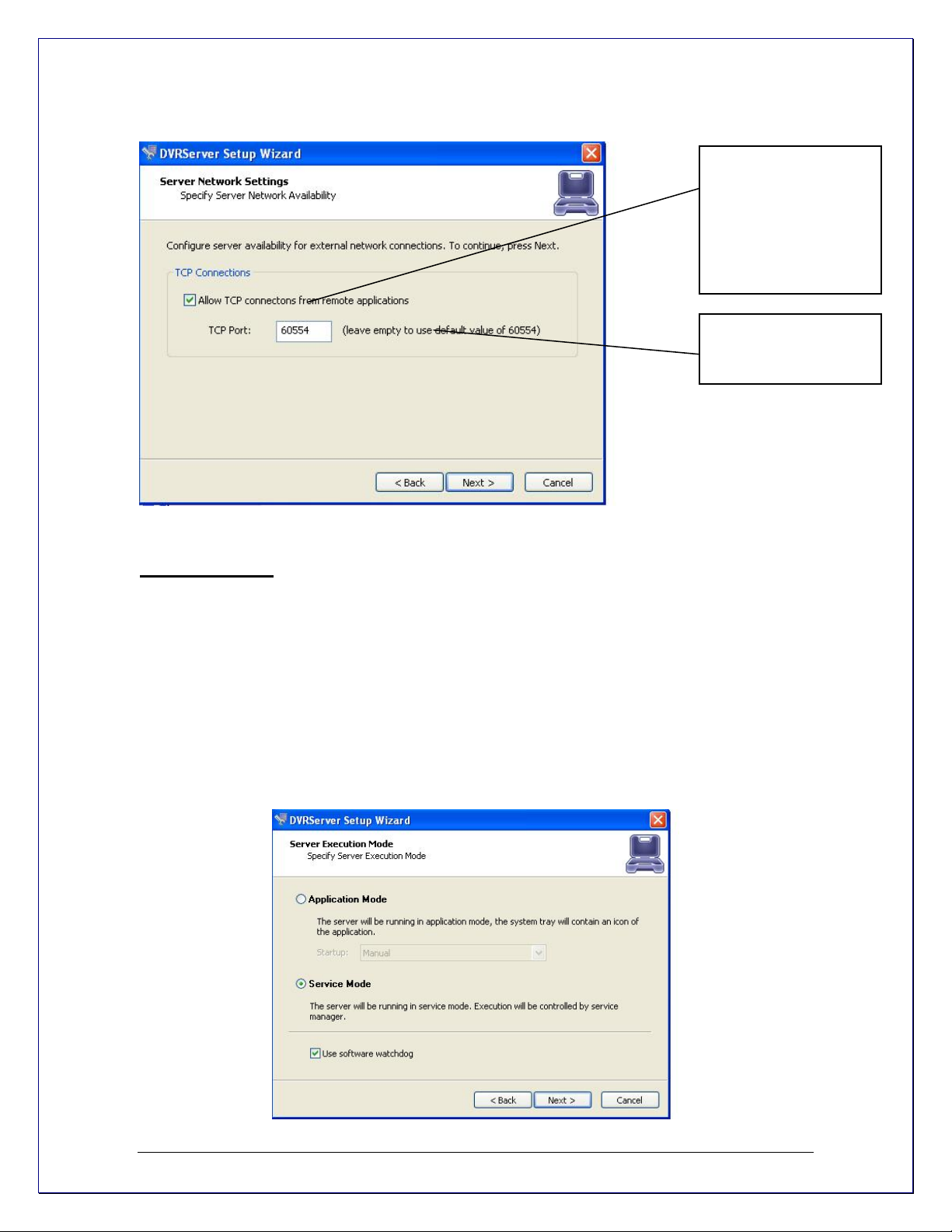
change that to any port that you would like as long as it is open
on your firewall. Please check with your network administrator
or internet service provider about your firewall settings Click Next
To enable TCP to
accept remote
connections can be
disabled or enable at
any time from the
Video Pilot server
settings.
This is the default Port
and it can be changed
to your preferences.
th
Screen- “Server Execution Mode” Here you have two options
4
Application Mode.
This means that the program
(Video Pilot) will need to somehow be manually started.
It then gives you a drop down list with options on how
that can happen. “Manually” is one option. That means
you will physically have to double click the program to get
it started. “Automatically with any user logon” is
another option. This option will turn the software on
when any user logs into Windows on that machine.
“Automatically with current user logon” is the last
option. This means that the user currently logged into
Windows, will be the user that activates Video Pilot upon
Windows login.
- 18 -
Page 19
Service Mode.
This option is RECOMMENDED. This
Option is an amazing feature offered exclusively through
Video Pilot. With Service Mode checked, the software will always
be running in the background even though nobody has yet
logged into Widows. This means you can lock everyone out
of windows and never have to worry about any of your data.
Also, if your power ever goes out, upon power recovery your
system will turn on and nobody needs to physically log into
windows or turn your Video Pilot program on, in order to
keep your data flowing both locally and remotely.
DVR SERVICE
Watchdog Service
Click Next
th
Screen - “Server Execution Control” Here depending on which option you
5
Chose in the previous screen, will show you your options.
Again your options will be limited to your previous selection.
Choose to either “Start Server Application” or “Start Server Service”
Click Next
th
Screen- “Stop Server Application” or “Stop Server Service” Just showing
6
you how you can now stop the Server if desired.
Click Next
th
Screen- “Wizard Complete”
7
Click Finish
Your Server Application is now complete.
End of Server Installation
- 19 -
Page 20
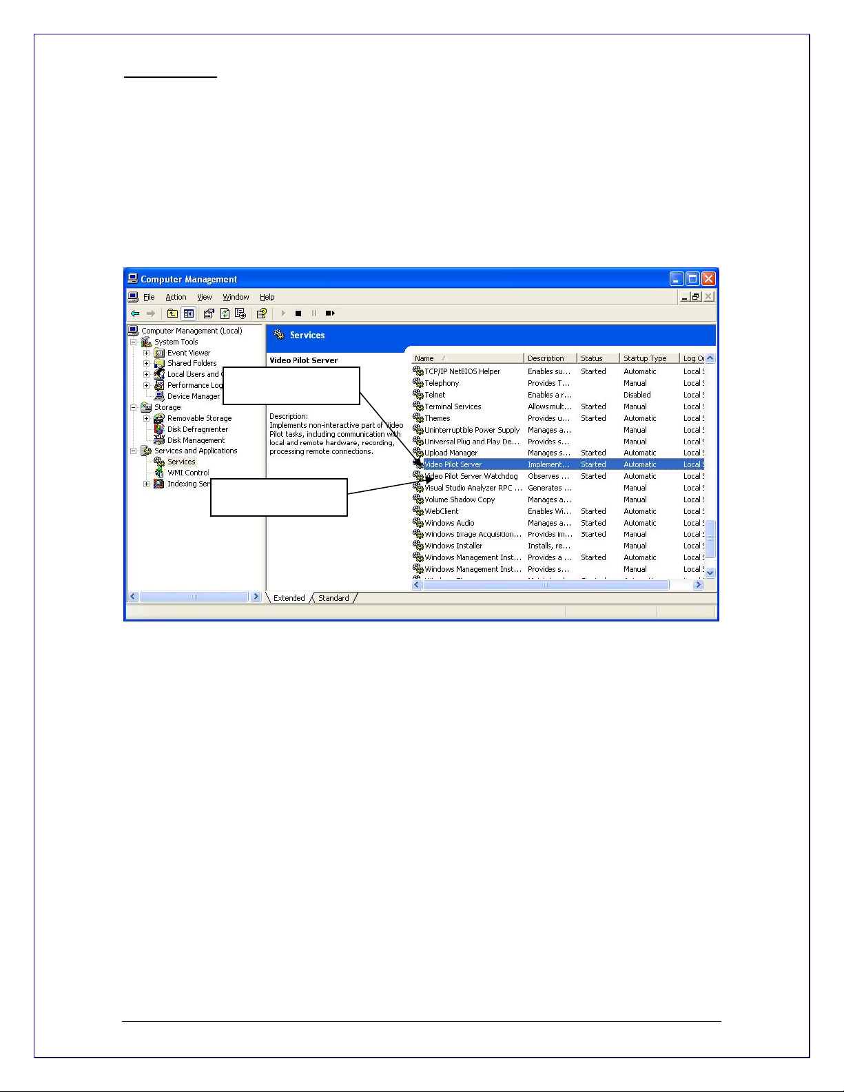
How to stop and start DVR services
The Video Pilot Software if it is setup on service Mode can be stopped by browsing the windows
services (see Page 17). Or by using the DVR SERVER WIZARD
Client Server Connections
Lets Begin Installing- Insert your Video Pilot CD into your CD drive, or if you have downloaded
Video Pilot begin the installation process by double clicking the Video Pilot file.
st
Screen- “Welcome to the Video Pilot Digital Video Recorder Setup Wizard”
1
Click next
nd
Screen- “Software License Agreement” Please read and choose accept
2
Click next
rd
Screen- “Release Notes”
3
Click next
th
Screen- “Select installation Destination” changing the location is optional
4
but not recommended.
Click next
th
Screen- “Select Components” Leave the
5
“VIDEO PILOT SERVER APPLICATION” unchecked, since we
are now installing only the Client or the GUI (Graphic User Interface)
portion of the Video Pilot package. The remaining options are for
the Video Pilot “Quick Guide” a quick guide to getting started (optional)
and the Video Pilot Demo connection, which will install a connection to
our live Demo (optional). You can always remove our connection at
a later time if you so choose. Click next
th
6
But not recommended. Click next
th
7
but optional. Click next
th
8
installed. Click Install
Screen- “Select Start Menu Folder” changing the location is optional
Screen- “Additional Icons” These are shortcuts and are recommende d
Screen- “Ready to Install” Video Pilot Video Recorder and options will now be
- 20 -
Page 21

th
Screen- “Completing the Video Pilot Digital Video Recorder Setup Wizard” Click Finish
9
Your Client Application Installation is now complete. Now let’s configure your VIDEO
PILOT Digital Video Recorder and get you viewing your cameras.
Control Server or Servers from your client application.
Double click your Video Pilot Client icon from your desktop.
We will now add your Server information to your Client application.
From the top bar menu
- Locate the word “Server”
- Choose “Add Server”
Add a new server
- The Add Server Wizard will open
- Choose Next
“Adding New Server” Screen is were you will enter
your data
.
The IP or the DNS of the
server you want to connect.
If the server is on the same
Machine Type localhost
The port your server is
running on
Remember Password: If
you choose to leave this field
unchecked every time you
try to log on the server will
request a password to let
you in.
Auto Connect on start
Auto reconnect on disconnection
- this will auto connect to your server as soon as you open the Client.
- will automatically try to reconnect you in the event of
disconnection.
Click Next
Now go to File – Save As- Find your Video Pilot Client on your desktop – highlight it so the
name appears in the save as portion- click save. It will tell you that Client already exists
and if you want to override it, click yes or your new server will not be saved in your server
list on the left and you will have to reenter your information when you reopen the program.
Wizard Complete. You should now have video feed of your cameras. The next two chapters will
teach you how to configure your DVR to your specifications.
End of Client Installation
- 21 -
Page 22

Chapter 3
Server Recording Properties-
Right click on your server
Choose Tasks
Recording Properties
Directories- This is where you will see your
available hard drive space. When you check and
highlight either drive, the details option below will
become available for further data entry. If you do
not want your C drive to be used for storage, do
not check it. If you do but only wish for a small
portion to be used, below is where we will define
that need.
End of Server Recording Properties
Statistics- Here you can check on used spaced
and available space left on the hard drives being
used by Video Pilot.
Priority- Your priority option, is for you to choose
which of your drives records first. You must first
check and then highlight (by clicking one time)
the drive you wish to customize in this portion
Quota - Here you chose the amount of space
you would like to designate for storage on that
particular hard drive. NOTE: NEVER, choose
100% for the C Drive. This may cause your
machine to eventually crash due to not available
virtual memory for page.
- 22 -
Page 23

Server Communication Properties-
Right click on your server
Choose Tasks
TCP Communication Properties
Tab Explanations:
Connections- Here you can see
at all times who is connected to
your server. The IP address, user
name and connection time can all
be seen. Click refresh at any time
for an updated list.
Settings for the HTTP Server for
remote connections from a webbrowser
End of Server Communication Properties
Server Watchdog
-
Your Server Watchdog performs an important operation, protecting your software from improperly
working due to system problems. Configuring your watchdog is not necessary, if you chose to
enable it during installation. The default settings will work well, however if you are having frequent
restarts or for maintance adjusting it may become vital.
Right click on your server
Choose Tasks
Manage Watchdog
Watchdog- In order to use
the Disable, Enable and
Properties tabs, you must
first highlight “Software
Watchdog” by left clicking
one time.
Click Properties
- 23 -
Page 24

Server Watchdog Properties
State- Start or Stop Running Watchdog.
Start Watchdog with Server-
Will begin the Watchdog application when server is started.
Enable Watchdog-
Will keep Watchdog running at all times.
Watchdog Operation
Grace Interval Seconds- The grace period given when
starting the application.
Reboot Interval Minutes- The amount of time Watchdog
will allow between reboots.
Number of Failure to Reboot- The amount of failed
attempts to fix, whatever problem has been detected, by restarting
only the Video Pilot application. Once this number has been
reached, Watchdog will now reboot Windows and the Video Pilot
application.
MaintenanceEnable Periodic Restart-
Enabling this feature will restart the Server Application at times
specified. It is recommended to restart the Server Application to
Refresh system resources. The Watchdog Server-Restart will go
Virtually unnoticed by the user.
If you made any changes click Apply then OK
Days or
Hours
End of Watchdog
- 24 -
Page 25

Server User Management-
You can start the Server
Security Wizard by rightclick on the server within
the Structure pane, then
Tasks and then by
choosing the “Server
Security Wizard”.
Explanations-
Create Users or modify existing user rights
This wizard guide you step by
step to add, remove, or modify
user permissions.
- 25 -
Page 26

System/User Permissions-
As you see Video Pilot User
Permissions provides Global
Scope permissions for better
user management.
In addition server administrators
can grant or revoke certain
permissions on a camera by
camera basis by checking this
box.
End of User Management
- 26 -
Page 27

Submitting A Problem Report-
End of Submitting A Problem Report
Manually- if you go to the Help icon, you will
see
“Problem Report Wizard”
Click on it and fill in the information
requested.
Video Pilot greatly appreciates your efforts
and takes all problem reports seriously.
Thank you again for your cooperation.
- 27 -
Page 28

Chapter 4
Setting up an IP camera…
There are two ways of setting up an IP camera to work with Video Pilot:
One-way is to let the software find the cameras automatically
Another is to manually input all of the camera’s IP information.
IP Servers
Note: Video Pilot also works with IP servers (encoders), which are Internet-based digital video
server appliances, capable of connecting one or several channels of video sources to distribute
their compressed live video into Intranet-Internet through Ethernet connection. IP Servers let you
use regular CCTV cameras as IP cameras; therefore getting rid of the sixteen camera limitation
that is seen with most DVR applications. Also if all of your cameras are connected to an IP server
with a WAN IP then you do not need to install Video Pilot on the premises, but instead you can
have Video Pilot running miles away (SEE PAGE 11) as long as it is connected to the internet.
Configure your IP cameras automatically.
-Right click on your server name
-Left click tasks
-Left click find network cameras.
-Choose Local Area Network and check
-“ Intelligent Camera Search”
-Click Next
Video Pilot will now begin scanning your network and
specified ports for any IP cameras. Once it is finished
it will give you a list of the cameras that it found and
give you an option to add them to Video Pilot.
Configure your IP cameras manually.
-Right click on the server name
-Choose tasks
-Choose camera setup wizard
-From the first window in the wizard select “Add new
Network (IP) Camera”
-Click Next.
Device Title - Name the camera.
Click Properties
Properties- Tab Explanations
Optional- if you know your
networks IP range,
you can search by the IP
range for the cameras as
- 28 -
Page 29

Access Tab
Note: If you are using a video server you can select the output
channel for this camera from the advanced menu.
Frame Tab
Dimensions- Quality of the picture. The higher quality you
choose the more space it will take
Color Mode- Color or black and white
Brightness, Contrast, etc… Change the appearance of
your video quality.
Select the camera type that you are using
from the drop down menu. Or if you are
using an IP server select from the same
Menu. (You can then select the camera
input from the advance menu).
Input the IP address of the IP Camera
- 29 -
Page 30

Setup Arecont Network IP Cameras
There are two ways of setting up an Arecont IP camera to work with Video Pilot:
One-way is to let the software find the cameras automatically
Another is to manually input all of the camera’s IP information.
When Arecont cameras are setup manually Video Pilot provide the following configuration
windows for fine tuning your Arecont cameras according to your preferences.
End of IP Camera Setup
- 30 -
Page 31

Setup SANYO standalone DVR
-Right click on the server name
-Choose tasks
-Choose camera setup wizard
-From the first window in the wizard select “Add new [SANYO DSR]”
-Click Next.
- Input the IP address and IP port of the Standalone
DVR
- Specify User name and Password
- Enter DSR video source
- Press Apply to save current settings
- 31 -
Page 32

Setup SANYO Pan Focus IP camera
-Right click on the server name
-Choose tasks
-Choose camera setup wizard
-From the first window in the wizard select
“Add new [SANYO Network(IP) camera]”
-Click Next.
Follow instructionshow to set IP camera
CCTV Camera Configuration
To setup a CCTV or Direct Show compatible camera we will use the Camera Setup Wizard
Right click on your server name located on the left side of the Video Pilot window
Choose tasks
Camera Setup Wizard Click Next
nd
Screen- “Camera Choice” Select the camera, which we will be
2
configuring.
Click Next
3rd Screen-
Device Title
Feel free to name your camera anything
you find helpful and then choose properties.
- 32 -
Page 33

Properties- Tab Explanations
Format Tab-
You will see this tab only if you have the Provideo Frame
Grabber
Frame Resolution- The default settings are recommended,
but you have the option to choose your format (NTSC, Pal, etc)
and your resolution size. Please note the larger
resolution size you choose the slower your frame rate may
become. Also high image quality requires more hard drive space.
Frame Tab – Available only if you have the Comart Frame Grabber
Dimensions- Here you can change your image resolution. Note:
The larger the resolution size you choose the slower your frame
rate may become. Also, the larger the image quality the more
space it requires.
Color Mode- Here you can choose to turn your color cameras
into Black and White. This is chosen sometimes to save storage
space.
Image Adjustment- You can change these settings here, or you
can change them from your “Toggle Video Amplification Pane” at
a later time see page 20
Defer changes until Apply- If checked this would ignore the
changes you made until “Apply” or “OK” have been hit.
- 33 -
Page 34

HiCap & XECAP Tab Available only if you have the Comart Frame
Grabber
Frame Rate - Here you can choose to increase or
decrease your frame rate. Note: If you are working
from a frame grabber you are limited to the total
frames allowed by your frame grabber.
Video System- choose your format NTSC, Pal, etc.
PTZ Camera Properties
PTZ Control: Video Pilot can interface RS-232, RS422
and RS-485. When the RS Control is selected, the
Properties button becomes available, for you to setup your PTZ camera.
- 34 -
Page 35

PTZ Protocols-Communication Settings
Choose which communication
Port the RS control is connected
to it.
Note: If you are using a Sanyo DVR with Sanyo PTZ’s connected to it, a converter is not
required. In this case this setup screen is not required.
Here you choose the communication
protocol supported by the PTZ camera
your installing.
PTZ Cameras often have DIP switches, or
configuration software that can be set to
different ID’s In order to be able to control
multiple PTZ cameras on the same RS
Controller.
- 35 -
Page 36

PTZ Control Pane
Save Presets, and Tours for PTZ Cameras
Click on the this Icon on the main
toolbar to get the PTZ control pane
Zoom IN
Zoom OUT
Manual and Auto Adjustments for
Focus and Iris
Presets and Tours can be configured from
the PTZ control window.
- 36 -
Manage PTZ tours camera by
camera by selecting the presets of
your choice and time between
them.
Page 37

Properties tab ended. Click ok and you will now return to the camera setup wizard.
Digital PAN-Tilt-Zoom on live view
Digital PAN-Tilt-Zoom on Playback
To Activate the Digital Pan-Tilt and zoom function on already recorded video just activating the
PTZ control pane from the archive window.
Click Next Video Compression
Enable Server Side Compression- Compresses video according to the
compression you choose. Video Pilot continuously integrates
compressions so feel free to check here every so often.
Right-Click on any camera
to Activate the Digital PanTilt and zoom function.
Then by activating the PTZ
control pane live streaming
video can be digitally
enhance.
- 37 -
Page 38

Enable Video Transfer Properties:
Enable time
lapse broadcast
on your remote
connection
only if needed.
Enable this feature
remotely if want to see
video on motion only.
This is very helpful
because frame rate is
distributed to the
cameras that have
motion only.
Adjust data controlled broadcast
if needed.
Image Quality
Properties- Here you adjust the quality. The higher you go the better your image quality will be for
that camera, however, it will give you slower frame rates and takes more storage space. (If you
make changes hit ok)
Click Next
Enable Video transfer recompression, can be
very useful for remote connections only.
The Video Pilot server can record up 3 mega
pixel images, but remotely using this feature a
user can receive more framerate with less image
quality
without changing the server properties.
5th Screen-
- 38 -
Page 39

Motion Analysis-
Use Motion- This box should be checked if you are interested in using Motion Detection. We
recommend you use motion detection for it will save you an abundance of well-needed storage
space. Choose Properties
Properties- Tab Explanations
Sensitivity Tab-
The sensitivity should be adjusted to a point where motion is
only seen by people and not by blinking lights, reflections, or
shadows, otherwise you will get “false motion” and Video
Pilot will be recording based on motion that does not exist.
Exclusion Tab-
If you are still getting motion from lights,
trees or things moving from an air-conditioner
or an open door then you can click on exclusion and block the object out
from the motion detection grid. You simply click on the grid boxes around
the object that you would like to exclude, to remove them from being seen
by the motion detection engine in Video Pilot.
- 39 -
Page 40

y
Format Tab- This controls the internal motion detection
analysis properties.
Analysis resolution- controls precision of the detection
process, the more resolution blocks is selected, the better
precision is, and however, the greater CPU consumption is
needed.
Smoothing- feature averages preliminary detection result
so that neighboring area is included into motion area as
well. Smoothing, however, slightly decreases motion
detection sensitivity.
Horizontal and vertical cell number- Defines the
dimensions of the target grid, which is used as output of
the motion detection algorithm. The defined cells are
shown. Click ok when finished
Click Next
th
Screen-
6
Data Recording
Here you can specify whether or not you
would like motion information and video
recording to be written to the hard drive. It is
recommended that you write both to the hard
drive, because it will make it much easier to
review your recordings with motion
information. With out motion being recorded to
the hard drive you will not be able to search
by general motion or defined motion regions (Smart Search
, see Page 55).
Advanced properties- Allows you to
setup time-lapse
recordings, and
Enable Motion control recording
Time lapse creates a small delay
between every frame that is written to
the hard drive, this will use the space
you have on your hard drive more
efficientl
.
.
- 40 -
Page 41

Time Lapse Recording:
Time Lapse recording properties can be accessed:
-Right click on your server
-Choose Tasks
-Camera setup Wizard
-Data recording
-Advanced properties
Time Lapse recording: The number of
frames to be record camera by camera. It
gives you the opportunity to use HD space
more efficiently. Less important cameras
can be set to record less frames than
others.
Motion Control Recording:
Motion Control Recording can be accessed:
-Right click on your server
-Choose Tasks
-Camera setup Wizard
-Data recording
-Advanced properties
Enable Motion control recording to
save disk space and make playback
more efficient.
Enable recording when motion is not
detected at selected frame rate.
When Motion occurs recording
frame rate goes to maximum
automatically.
- 41 -
Page 42

Click Next
th
Screen- “Action Summary”
7
This page of the camera setup wizard gives you a summary of all of the changes that you have
made throughout the wizard. You should set up every camera that you have connected to your
DVR one by one and disable the inputs that have nothing connected to them. The camera setup
wizard only has to be run the first time that you install Video Pilot to setup all of your inputs or
afterwards to make changes to camera names and/or motion detection, recording, etc, properties.
Click Next
th
Screen- “Wizard Complete” Congratulations, you have now set up your camera.
8
Click Finish
Video Adjustments:
Toggle Video Amplification Pane
End of Camera Configuration
Video adjustment can adjust
every individual camera with its
own settings.
- 42 -
Page 43

Exclusivity Mode (Windows lock out feature):
Exclusivity Mode is to make sure that operator cannot get
access to Windows operating system. On the other hand
they can have access to Video Pilot software only. This is
to ensure uninterrupted server operation and stability
eliminating the human error.
Exclusivity is a password protected function.
- 43 -
Page 44

Chapter 5 – Sanyo DSR Settings
Recording Status
1. Press Start to activate recording on DSR unit
2. Press Stop to stop recording on DSR unit
Clock Set
1. Select the Month/Day/Year from the pull-down
calendar.
2. Adjust time through Time Control.
3. Press Apply to set current time.
Daylight Saving/Ext Clock set
1. Check Use Daylight Saving Mode to automatically
adjust to daylight saving.
2. Set the date/time at which to switch from standard
time to daylight saving from the pull-down menu on
the screen.
3. Set the date/time at which to switch from daylight
saving to standard time from the pull-down menu on
the screen.
4. Select “Adjust Time” from the pull-down menu on
the screen.
5. Press Apply to save current settings
- 44 -
Page 45

Holiday Set
When a day is specified as a holiday, timer recording for
that day will be carried out as if it were a Sunday. Dates
such as national holidays and company off days should
be set as holidays when you want those dates to have
the same security as Sundays
1. Put the checkmark and specify the day to be treated
as a holiday from the pull-down menu on the screen.
2. Press Apply to save current settings
Recording Area Set
The unit’s hard disk is separated into three independent
recording areas. The memory capacity for each area is
allocated in percentage.
TOTAL CAPACITY – this section displays the total
capacity of the hard disk
Area Full Reset
When the overwrite setting is “OFF”, recording will be
automatically stopped when the corresponding recording
area has been filled with image data. In such case
“AREA FULL RESET” can be clicked to overwrite from
the beginning of normal recording area, “ALARM AREA
FULL RESET” can be clicked to overwrite from the
beginning of alarm recording area, and “ARCHIVE ARE
FULL RESET” can be clicked to overwrite from the
beginning of archive area.
Recording Conditions Set
Set the permission for overwriting to recording areas or
remaining-space warning level as described below.
Normal Recording area overwrite
When the normal recording area has been filled with
data, this setting indicates whether recording will be
stopped or continued by overwriting the recorded images
currently stored on the hard drive
Alarm Recording are overwrite
When the alarm recording area has been filled with data,
this setting indicates whether recording will be stopped
or continued by overwriting the recorded images
currently stored on the hard drive
Series Recording
This setting is used when connecting multiple digital
video recorders. Series recording can be used to ensure
that, when the capacity of the normal recording area is
- 45 -
Page 46

reached, recording continues automatically on the next digital video recorder
Remaining Disk Warning
Set the remaining-space warning level from the pull-down menu. In situations where the
overwrite setting for the normal recording area and the alarm recording area is “OFF”, you can
have the unit issue a warning as soon as the remaining space is either of these areas a specific
level.
Auto Delete
You can set the storage period for recorded data within a range “1 DAY”-“99 DAYS”
Press Apply to save current settings
Normal REC Mode Set
1. Set Picture quality from the pull-down menu on the
screen
2. Select Recording Rate for normal recording from pull-
down menu on the screen
3. Select Record Program Group from the pull-down
menu on the screen. Settings for program groups should
be made separately as described “Program Rec Set”
4. Select Audio Recording from the pull-down menu to
enable
5. Press Apply to save current settings
Program REC Set
When monitoring a number of cameras connected to this
digital video recorder, a separate recording rate can be
set for each camera. In addition, video recorded from
each camera and the corresponding recording rates can
be set in programs with up to tour patterns, thus
facilitating the simple specification of programs for timersetting and normal recording setting menus.
1. Select “PROGRAM” from the pull-down menu on the
screen
2. Select individual cameras rate from the pull-down
menu on the screen
3. Press Apply to save current settings
- 46 -
Page 47

Timer Set
Set timer operation and timer recording conditions on a
day-specified basis
WEEK – These fields specify the days of the week for
timer
Start – These fields are used to enter the time at which to
start timer recording.
Stop – These fields are used to enter the time at which to
stop timer recording.
Program - To carry out program recording, select program
1 to 4
FPS – These fields set the recording rate
Set – Set On/Off timer recording
Over 24H – Use to set a timer for over 24-hours
continuous recording.
Press Apply to save current settings
Alarm REC Mode Set
1. Select a mode using “Alarm Recording” from the pull-
down menu on the screen. Setting “OFF” indicates that
unit does not perform alarm recording.
2. Select the picture quality from pull-down menu for alarm
recording. Default setting is “ENCHANCED”
3. Enable/Disable Audio Recording
Alarm Interface
4. Select “ALARM INTERLEAVE” from the pull-down menu
on the screen. The value “ONLY” indicates that video is
recorded only from cameras with an alarm occurring. “SW”
indicates that Recording is switched between camera
video including an alarm and video from all connected
cameras.
5. Select Recording Rate from pull-down menu. The letter
“A” will be displayed in front of recording rates that can be
set for audio recording
PRE-Alarm Recording
6. Select “ON” or “OFF” using “PRE-ALRM RECORDING”
from pull-down menu on the screen
7. Set Recording Rate for pre-alarm recording from pull-
down menu on the screen
8. Set the Duration for pre-alarm recording using “DURATION” from the pull-down menu on the
screen.
Press Apply to save current settings
- 47 -
Page 48

Display Set
Set conditions for the display of data on the unit’s monitor by
ENABLE/DISBALE each item.
DATE – Set whether the current date or recording date will be
displayed.
TIME – Sets whether the current time or recording time will be
displayed
QUALITY – Sets the picture quality for recording or playback
AUDIO – Sets the display condition for audio recording
ALARM COUNT – Displays the number or recorded alarms
ALARM TYPE – Sets the alarm recording type. For alarm recording
“ALARM” is displayed. For pre-alarm recording “PRE” is displayed.
TITLE – Sets the display condition for camera title
Press Apply to save current settings
Buzzer Set
Set a warning buzzer to sound for alarms or when the hard disk
space reaches zero as described below.
ALARM – Sound a buzzer when an alarm is detected.
DISK FULL – Sound a buzzer when the amount of data stored in
each of the hard disk’s recording areas has reached the remaining
space warning level.
DISK ERROR – Sounds a buzzer when a hard-disk error occurs
LOCK WARNING – Sound a buzzer when an operation button not
permitted for the current user level is pressed while the security lock
is set. Specifically, the buzzer sounds twice with an interval of
approximately 0.5 seconds
KEY IN – The buzzer emits a key-operation sound each time a
button is pressed.
NON REC – Sounds a buzzer when recording is stopped.
Press Apply to save current settings
HDD Set
This screen provides information regarding the hard disk
Hard disk capacity
This item displays the total capacity of the hard disk. If hard disk
expansion is carried out, a value will be displayed for each disk
Mirroring
This item displays in the mirroring-type setting.
Payback drive
This item indicates which of the hard drives will be used to provide
video for playback when mirroring has been turned on.
- 48 -
Page 49

Network Set
Network settings must be made in advance on the unit whenever it is
to controlled via network. Once this has been done, settings can then
be changed from the controlling PC.
IP ADDRESS – Allows the unit’s IP Address to be modified
SUBNET MASK – Allows the unit’s subnet mask to be modified
GATEWAY – Allows the unit’s gateway to be modified
PORT – Allows the unit’s port number to be modified. Set within the
range of 1 to 65535 (default setting: 80)
Password Setting
This item allows you to set a password for each different user level.
Use between 4 and 8 alphanumeric characters for passwords.
Network Speed
This item lets you modify the network speed setting. When the unit is
reset, the network speed setting will revert to default value (No Limit)
Press Apply to save current settings
RS-485 Set
This screen displays settings relevant to the unit’s interfaces
DATA SPEED – Displays the RS-485 communication speed
STATUS INFO – Displays whether or not status information will be
transmitted during RS-485 communication
ALARM INFO- Displays whether or not alarm information will be
transmitted during RS-485 communication
ADRESS – Displays the address when RS-485 has been selecte d
Mask Set
Use the following procedure to set video from individual cameras to the
masked by a gray pattern when it is not needed on a monitor screen.
MASK – Turns masking on/ff
TIME PERIOD – Selects one of the time periods, T-1 through T-4.
CH – Turns each channel’s masking on or off individually for the main
monitor, the monitor 2, and network video
Press Apply to save current settings
- 49 -
Page 50

Power Loss/Used Time
Check the date time of power losses and the amount of hard disk
usage as described below. Data for the four most recent power
losses is displayed.
POWER – Displays the number of power losses and the date and
time of occurrence and restoration for the four most recent power
losses.
USED TIME – Displays the usage time for the digital video recorder
FIRMWARE – Displays the firmware version
Initialization Log
Check the records for hard-disk initialization and area resetting.
The eight most recent records are displayed.
DATE – Displays the date of the operation
TIME – Displays the time of the operation
AREA – Displays the area in question and the corresponding
operation content.
- 50 -
Page 51

Chapter 6 - Sanyo Network Camera Settings
Camera Settings
Specify Network Host name or IP
Address of Network Camera
Specify IP Port
Provide User name and Password for
access to Network (IP) camera
Select Image resolution from pull-down
menu
Select Image quality from pull-down
menu.
Set Day/Night mode from pull-down
menu. There are 3 options: AUTOSwitches the video display automatically
between color and black–and-white
depending on daytime or nighttime
brightness, COLOR – Always displays
the color video image, and B/W –
Always displays the black-and-white video image.
AUX – These buttons are reserved for additional functions. The function corresponding to the
number selected in the pull-down menu will be performed. The function allocated to respective
numbers depends on the camera models.
Recording Settings
Image Transmission – Set the image
transmission mode to “HTTP”
Live/Normal Record
Configure the preferences for the live
video display and normal recording
format (Resolution and Quality)
HTTP Alarm Record
Configure the preferences for alarm
recording format
Resolution – Image resolution
Quality – Image quality
Buffer Size – select the option for
specifying the buffering capacity on the
camera used for recording the alarm
image.
Pre/Post – Configures the recording capacity ratio between the pre- and post-alarm image
recording.
Rate – Configures the recording rate for the alarm image.
Duration – Specifies the duration of each alarm image to transfer.
FTP Connection (Set the image transmission to “FTP”)
Please provide following information for FTP transmission:
- Server Address
- User ID
- Password
- FTP passive
- Camera ID
- 51 -
Page 52

Alarm Record
Configure the preferences for alarm recording format.
- Resolution
- Quality
Buffer Size – select the option for specifying the buffering capacity on the camera used for
recording the alarm image.
Pre/Post – Configures the recording capacity ratio between the pre- and post-alarm image
recording.
Rate – Configures the recording rate for the alarm image.
Duration – Specifies the duration of each alarm image to transfer.
TX Rate – Configures the interval for transferring the alarm image.
Clock Settings
Date – Set the date for the clock
build into the camera
Time - Set the time for the clock
build into the camera
Time Zone – Selects the time
zone where the camera is used
Clock Adjust – Can be used to
adjust date and time
automatically.
OFF – Automatic clock
adjustment is not used
ON (NTP) – Adjust the
clock automatically by retrieving
the date and time information from
NTP server.
LOGIN (PC) - Performs
the automatic clock adjustment
during login process by retrieving
the date and time information from
the PC used for accessing the
Camera
Time to Synchronize – Specify the time for performing the automatic clock adjustment
NTP Server Address – Enter the domain name or IP address of the NTP server used for
retrieving the date and time information
Daylight Saving Mode - When you set this setting to “USE”, the time schedule switches between
the standard tie and the daylight saving time automatically according to the Time Zone area
specified above
- 52 -
Page 53

E-Mail Settings
Send Message – When sending the
alarm notification e-mail, set this
value to “ON”
The following mail server
information is specified in these
setting items
SMTP Server Address
SMTP Server Port
User mail address – Specifies the
sender’s e-mail address
Recipient mail address – Specifies
the recipient’s e-mail address to
which the alarm notification is sent.
You can specify up to five e-mail
addresses.
Authentication Settings
Authentication
User ID
Password
POP3 Server Address
Subject – the title appearing at the beginning of the message
Text – Additional comment appended to the basic message
Network Settings
Title – Specifies the camera title. The
title can be up to 16 alphanumeric
characters.
IP – Select the method for configuring
the camera IP address
FIX – Manually configure the
IP address.
DHCP – Automatically
allocates the IP address
Port – You can assign a value
between 1 and 65535 to SSL port
number
Subnet Mask – When the [IP
Address] setting is “FIX”, enter the
subnet mask
Gateway - When the [IP Address] setting is “FIX”, enter the subnet mask
DNS - When the [IP Address] setting is “DHCP”, select the method for configuring the DNS server
address.
FIX – Manually configure the DNS server address
DHCP – Automatically allocates the DNS server address
DNS Server Address – When the [DNS] setting is “FIX”, enter the DNS servers address
SSL – Select “ON” when you want to use SSL encryption for the video signal.
Network Speed – Select the data transfer speed in consideration of the network environment
Password – Specify the login password according to each user name (guest/admin)
- 53 -
Page 54

Chapter 7
How to Playback Video-
To playback recorder video
Right click on your server name
Choose tasks
Open archive
You can also
Right click on any camera view and
Choose open archive
Your archive pane will now open
Playback Window Structure-
Now that you are in the playback screen, the
structure pane on the left
lists all of the cameras that you have
recordings for
To Navigate through the Video -
Double click on the camera you wish to
playback (This camera will now appear with
footage on the video screen)
The solid green line on the bottom represents
time. The light green lines represent
recorded video. The orange lines represent
motion information.
Fast forward & Rewind
You have a jog dial on the bottom of the screen, which you can drag in either direction to browse
through your video in high speeds.
Another way to fast forward is to use the arrow controls on top of the screen in which you can
define how many increments of time you would like to move through the video.
Playback Motion Only-
Located at the top of your Archive Pane, there are two buttons that allow you to seek video with
actual motion in return saving you time.
With the camera you wish to review selected and showing in your video screen
Choose either “seek previous motion” or “seek next motion”
There are basic VCR controls on
the bottom of the playback screen,
which you can use to play, pause,
forward, and rewind.
- 54 -
Page 55

Smart Search-
You can also search through video not only by motion in the screen, but also by motion in a
specific part of your camera screen. Through Video Pilot’s playback screen, you can define a
specific object in your view, or define a path, and seek through motion only in that specific region.
This process is very commonly referred to as “smart search”.
Define motion of interest –
Click on the navigation menu at the top of the playback screen
Click on “Define region of motion interest”.
While having the left button
continuously pressed, drag the
mouse over the area you would
like to see motion in (This will
create a grid in that area). You can
also select multiple regions.
Click on “seek to previous motion” or “seek to next motion” to search through motion
in the defined area or areas.
End of Playback Video
- 55 -
Page 56

Export Video To export video, you first have to select the section of recordings that you want to export to a
different location (This will also prevent it from getting overwritten).
To select video
Click on Edit at the top of the playback screen
Click on Export Wizard
Choose which camera to
export.
Choose compression.
.
Click next.
Select the start and finish
times of the video clip that you
want to export.
The Wizard will guide to the next step for you do designate to which drive or folder to save the
export video.
- 56 -
Page 57

Note: To play back the Video Pilot AVI file, a codec (a small executable file) will have to be
installed in order for your media player to recognize the Video Pilot video file. The codec can be
downloaded from http://www.sanyocctv.com
Export Snapshots.
Another way to export video is to save one frame at a time, like a snapshot.
First pause the video on the picture that you would like to copy,
Click on edit
Choose “save current frame as…”
Pick a location and filename for your image and
Click save.
Now you will have the image stored so that you can print, e-mail, or enhance that snapshot.
End of Export Video
- 57 -
Page 58

g
Layouts
Create custom Layouts by grouping
cameras from different DVR
Servers/Locations into groups for more
efficient monitoring, and better
management.
For example group together all outdoor cameras from different location or
all POS cameras from all re
isters.
Individual Layouts can be activated by double-click on them with the mouse.
Users now can perform playback and other function by Right-click on the camera of their interest.
- 58 -
Page 59

Layout Sequences
When Layouts are created, they can be used for Sequencing.
To create Sequences Right mouse click on Layout Sequences.
Set time interval
between layouts
Manage priority or remove
layouts of your choice.
Choose given
Layouts for adding
them in a sequence.
- 59 -
Page 60

Chapter 8
Upgrading Video Pilot software to a newer Version.
To check for upgrades and new free versions you can always visit
Updating the software requires all DVR services to stop before Installation (see page 17-18).
During the installation of the new version you will encounter the following message:
After the above step you can continue with the installation. See Chapter 2
Recommended
To keep all current
configurations of your server
www.sanyocctv.com.
To start a new database. By doing
that all previous settings and
configurations will be erased and a
new database will be created.
- 60 -
Page 61

rate,
Specifications
Table of Recording rate and size
This product’s recording time can be changed by modifying the recording rate and the frame size.
The following table provides reference values for frame resolution and recordin g rate for
individual camera in a situation where video is recorded to the normal recording area of this
product’s hard disk.
Frame Resolution Definition (in Pixels):
QCIF -160x120, 176×120, 180x120
CIF - 320x240, 352×240, 360x240
2CIF - 640x240, 704×240, 720x240
4CIF - 640x480, 704×480, 720×480
1.3 Mpixel - 1280x1024
2.1 Mpixel - 1600x1200
3.0 Mpixel – 1920x1080
5.0 Mpixel - 2560x1600
GB per day at defined frame resolution Recording
QCIF CIF 2 CIF 4 CIF 1.3 MPixel 2.1 MPixel 3 MPixel 5 MPixel
FPS
30.00
25.00
20.00
15.00
10.00
7.50
5.00
4.00
3.00
2.00
1.00
0.50
0.25
0.10
0.05
Example: How many days can I record if I have 20 cameras and 500GB hard disk?
Calculation:
16 Cameras x 3.885 GB/per day = 62.16 GB
2 Cameras x 8.294 GB/per day = 16.59 GB
1 Camera x 54 GB/per day = 54.00 GB
1 Camera x 41.05 GB/per day = 41.05 GB
You need total: 62.16 + 16.59 + 54.00 + 41.05 = 173.80 GB to record video for one full
day.
Using 20 cameras at different resolutions and 500 GB hard drive you can record video
for 500/173.8 = 2.87 Days or 2 Days, 20 Hours and 52 Minutes
3.885 15.54 31.08 62.21 324.00 519.00 777.00 1231.50
3.237 12.95 25.90 51.84 270.00 432.50 647.50 1026.25
2.590 10.36 20.72 41.47 216.00 346.00 518.00 821.00
1.942 7.770 15.54 31.10 162.00 259.50 388.50 615.75
1.295 5.180 10.36 20.74 108.00 173.00 259.00 410.50
0.971 3.885 7.770 15.55 81.00 129.75 194.25 307.88
0.647 2.590 5.180 10.37 54.00 86.50 129.50 205.25
0.518 2.072 4.144 8.294 43.20 69.20 103.60 164.20
0.388 1.554 3.108 6.221 32.40 51.90 77.70 123.15
0.259 1.036 2.072 4.147 21.60 34.60 51.80 82.10
0.129 0.518 1.036 2.0736 10.80 17.30 25.90 41.05
0.065 0.259 0.518 1.037 5.400 8.650 12.95 20.53
0.032 0.129 0.259 0.518 2.700 4.325 6.475 10.26
0.013 0.052 0.104 0.207 1.080 1.730 2.590 4.105
0.006 0.026 0.052 0.052 0.540 0.865 1.295 2.053
• 16 cameras record at CIF resolution and 7.5 FPS on each camera.
• 2 Cameras record at 4CIF resolution and 5 FPS on each camera
• 1 Camera records at 1.3 MPixel and 5 FPS
• 1 Camera records at 5 Mpixel and 1 FPS
- 61 -
Page 62

Minimum System Requirements
Number of video
sources
16 16 DSR Intel Pentium 4 3.0Ghz, 512Mb
Camera and Video Stream
18 16 DSR + 2 Mega Pixel
Cameras
24 16 DSR + 8 Pan Focus
cameras
24 16 DSR, 6 Pan Focus, and 2
Mega Pixel Cameras
32 16DSR + 16 Pan Focus Intel Pentium Core 2 Duo
Recommended System
Types
RAM.
Intel Pentium Core 2 Duo
2.667Ghz, 1.5Gb RAM
Intel Pentium D 3.4 GHz,
1Gb RAM
Intel Dual Xeon 3.4 GHz,
2Gb RAM
2.667Ghz, 1.5Gb RAM
- 62 -
Page 63

A
Access Tab................... 29
Action Summary ........... 42
Analysis resolution........ 40
Application Mode.......... 18
archive pane................. 54
AVI................................ 57
C
Camera Configuration .. 32
CCD cameras................. 9
Client............................. 13
Client Server Connections
.................................. 20
Comart Frame Grabber 34
D
Data Recording............. 40
Device Title................... 32
E
Enable Periodic Restart 24
Enable Server Side
Compression............ 37
Events........................... 10
Exclusion Tab............... 39
export video.................. 56
export wizard ................ 57
F
Format Tab................... 40
FPS recording................. 9
FPS viewing.................... 9
Frame Rate..................... 9
Frame Tab.............. 29, 33
Full Screen.................... 10
G
Grace Interval Seconds 24
H
Horizontal and vertical cell
number..................... 40
How to Playback Video 51,
52, 53, 54
I
Install Server
Configuration ............17
IP Cameras.....................7
IP servers......................28
M
Maintenance..................24
Maximize.......................11
Motion............................54
Motion Analysis.............39
Motion Detection...........39
motion in a specific part.55
motion of interest...........55
N
Navigate through the
Video.........................54
Number of Failure to
Reboot ......................24
O
Open Configuration.......10
Operation ......................24
P
Pane..............................10
Permissions...................26
Playback Motion Only...54
Playback Video 51, 52, 53,
54
Playback Window
Structure ...................54
Problem Report.............27
Provideo Frame Grabber
..................................33
PTZ Cameras..................8
PTZ Control...................10
R
Reboot Interval Minutes 24
Remote Viewing............14
S
Save Configuration........10
Screen Footer ...............11
Sensitivity Tab .............. 39
Server........................... 12
Server Communication
Properties................. 23
Server Installation......... 16
Server Recording
Properties................. 22
Server User Management
.................................. 25
Server Watchdog.......... 23
Service Mode................ 19
Setting up an IP camera…
.................................. 28
Setup Camera .............. 32
Show Motion................. 11
Smart Search................ 55
Smoothing..................... 40
snapshot....................... 57
Software Activation....... 17
State ............................. 24
Stream Selection .......... 11
Structure Pane........ 10, 11
Submitting A Problem
Report....................... 27
T
TCP Communication
Properties................. 23
Toggle........................... 10
Toolbar.......................... 10
U
USB Cameras................. 8
User Management........ 25
V
Video amplification ....... 10
Video Compression...... 37
Views............................ 10
W
Watchdog...................... 23
Web Cameras................. 8
What are Frame Grabbers
.................................... 9
Wizards......................... 10
- 63 -
Page 64

Enter Notes Here_____________________________________________________________________________
_____________________________________________________________________________
_____________________________________________________________________________
_____________________________________________________________________________
_____________________________________________________________________________
_____________________________________________________________________________
_____________________________________________________________________________
_____________________________________________________________________________
_____________________________________________________________________________
_____________________________________________________________________________
_____________________________________________________________________________
_________________________________________
Additional References:
- 64 -
Page 65

For Your Records
Dealer Name:
Dealer Address:
Date Of Purchase:
Purchase Location:
Software Activation Key:
Dates Software Last Upgraded:
_______________ _______________ _______________ _______________
_______________ _______________ _______________ _______________
_______________ _______________ _______________ _______________
_______________ _______________ _______________ _______________
_______________ _______________ _______________ _______________
_______________ _______________ _______________ _______________
_______________ _______________ _______________ _______________
_______________ _______________ _______________ _______________
- 65 -
Page 66

Sanyo Fisher Company
Security Products Division
21605 Plummer St.
Chatsworth, CA, 91311
Tel: 888-893-7403
Tel: 818-998-7322
Fax: 888-717-2716
www.sanyocctv.com
- 66 -
 Loading...