

Page 1

INSTRUCTION MANUAL
DVR Utility Software
VA-SW814
VA-SW81LITE
Page 2

CONTENTS
DVR UTILITY SOFTWARE FEATURES . . . . . . . . . . . 2
SOFTWARE VERSION . . . . . . . . . . . . . . . . . . . . . . . . 2
NETWORK CONFIGURATION . . . . . . . . . . . . . . . . . . 3
SYSTEM REQUIREMENTS. . . . . . . . . . . . . . . . . . . . .5
TCP/IP SETTINGS . . . . . . . . . . . . . . . . . . . . . . . . . . . . 6
INSTALLING THE SOFTWARE. . . . . . . . . . . . . . . . . . 7
LOGGING IN/LOGGING OFF/DISPLAY LANGUAGE
SETTING . . . . . . . . . . . . . . . . . . . . . . . . . . . . . . . . . . . 9
■
User Level . . . . . . . . . . . . . . . . . . . . . . . . . . . . . . 9
■
Logging In . . . . . . . . . . . . . . . . . . . . . . . . . . . . . 10
■
Logging Off . . . . . . . . . . . . . . . . . . . . . . . . . . . . 11
■
Display Language Setting . . . . . . . . . . . . . . . . 11
■
Display While Communication is in
Progress . . . . . . . . . . . . . . . . . . . . . . . . . . . . . .11
BASIC WINDOW FLOWCHART . . . . . . . . . . . . . . . . 12
FUNCTIONS OF EACH MAIN WINDOW
(MONITORING, RECORDING AND PLAYBACK
WINDOW) COMPONENT. . . . . . . . . . . . . . . . . . . . . . 13
BASIC NETWORK SETTINGS . . . . . . . . . . . . . . . . . 16
OPERATION OF SETTING BUTTONS . . . . . . . . . . . 19
INITIAL SETUP (SETUP WINDOW) . . . . . . . . . . . . . 20
■
SYSTEM SETUP tab . . . . . . . . . . . . . . . . . . . . .20
■
REGISTER DVR tab . . . . . . . . . . . . . . . . . . . . . 22
■
ADVANCED SETUP tab . . . . . . . . . . . . . . . . . . 29
■
USER ID tab. . . . . . . . . . . . . . . . . . . . . . . . . . . . 30
CLOCK AND SYSTEM UPDATE SETTINGS . . . . . . 34
■
CLOCK SET tab . . . . . . . . . . . . . . . . . . . . . . . . 34
■
SYSTEM UPDATE tab. . . . . . . . . . . . . . . . . . . . 35
■
INFORMATION1 tab . . . . . . . . . . . . . . . . . . . . . 36
■
INFORMATION2 tab . . . . . . . . . . . . . . . . . . . . . 38
MENU SETTINGS (MENU WINDOW) . . . . . . . . . . . . 39
■
LANGUAGE/D.S.TIME SET tab . . . . . . . . . . . . 39
■
REC MODE SET tab . . . . . . . . . . . . . . . . . . . . . 41
■
TIMER REC SET tab . . . . . . . . . . . . . . . . . . . . . 44
■
HOLIDAY SET tab . . . . . . . . . . . . . . . . . . . . . . . 46
■
DISPLAY/BUZZER SET tab . . . . . . . . . . . . . . . 47
■
MONITOR SET tab . . . . . . . . . . . . . . . . . . . . . . 49
■
TITLE/MOTION SET tab . . . . . . . . . . . . . . . . . . 51
BROADCAST TRANSMISSION SETTINGS
(BROADCAST WINDOW) . . . . . . . . . . . . . . . . . . . . . 52
IMAGE DISPLAY WINDOWS . . . . . . . . . . . . . . . . . . 54
■
Display Screen Type . . . . . . . . . . . . . . . . . . . . 54
■
Switching Display Windows . . . . . . . . . . . . . . 55
■
Sequence Display Function. . . . . . . . . . . . . . .57
■
Title Bar . . . . . . . . . . . . . . . . . . . . . . . . . . . . . . . 58
■
Zoom Function . . . . . . . . . . . . . . . . . . . . . . . . .59
■
Full Screen Function . . . . . . . . . . . . . . . . . . . . 60
MONITORING LIVE IMAGES . . . . . . . . . . . . . . . . . . 61
■
Monitoring in a QUAD/SINGLE Screen . . . . . . 61
■
Monitoring with MULTI Screens . . . . . . . . . . . 62
■
Disconnecting DVRs . . . . . . . . . . . . . . . . . . . . 63
■
Image Audio Output . . . . . . . . . . . . . . . . . . . . . 63
RECORDING IMAGES. . . . . . . . . . . . . . . . . . . . . . . . 64
■
Normal Recording . . . . . . . . . . . . . . . . . . . . . . 64
■
Timer Recording . . . . . . . . . . . . . . . . . . . . . . . . 66
■
Alarm Recording. . . . . . . . . . . . . . . . . . . . . . . . 67
PLAYING BACK RECORDED IMAGES . . . . . . . . . . 68
■
Playing Back Recorded Images . . . . . . . . . . . 68
■
Functions of Each Playback Control Panel
Component . . . . . . . . . . . . . . . . . . . . . . . . . . . . 69
SEARCHING . . . . . . . . . . . . . . . . . . . . . . . . . . . . . . . 70
■
Time/Date Search . . . . . . . . . . . . . . . . . . . . . . . 70
■
Alarm Search . . . . . . . . . . . . . . . . . . . . . . . . . . 71
■
Alarm Thumbnail Search. . . . . . . . . . . . . . . . . 73
SAVING STILL IMAGES . . . . . . . . . . . . . . . . . . . . . . 74
DOWNLOAD . . . . . . . . . . . . . . . . . . . . . . . . . . . . . . . 75
■
Specifying the Image Range . . . . . . . . . . . . . . 75
■
Functions of Each Download
Window Element . . . . . . . . . . . . . . . . . . . . . . . . 76
■
Basic Downloading Operations
(Individual Download) . . . . . . . . . . . . . . . . . . . 78
■
Preset List Operations
(Batch Downloads) . . . . . . . . . . . . . . . . . . . . . . 80
TIMER DOWNLOAD . . . . . . . . . . . . . . . . . . . . . . . . . 81
TAMPER DETECTION . . . . . . . . . . . . . . . . . . . . . . . . 89
MP2 Viewer . . . . . . . . . . . . . . . . . . . . . . . . . . . . . . . . 90
■
Main Functions . . . . . . . . . . . . . . . . . . . . . . . . . 90
■
Operating Environment . . . . . . . . . . . . . . . . . . 90
■
Installation/Saving Location . . . . . . . . . . . . . . 90
■
Starting . . . . . . . . . . . . . . . . . . . . . . . . . . . . . . . 90
■
Window Structure and Functions of
Each Part . . . . . . . . . . . . . . . . . . . . . . . . . . . . . . 91
■
Opening (Playing) Files . . . . . . . . . . . . . . . . . . 93
■
Saves a Still Image . . . . . . . . . . . . . . . . . . . . . . 97
■
Prints Still Images . . . . . . . . . . . . . . . . . . . . . . 97
■
Searches for Images . . . . . . . . . . . . . . . . . . . . 98
■
Detecting Tampering of Images . . . . . . . . . . . 98
English
1
Page 3

DVR UTILITY SOFTWARE FEATURES
This software is a remote monitoring system for digital video recorders (DVR) and computer terminals
that are connected via a network. It includes an extensive range of functions that are designed to make
optimal use of the latest in technology and network features. It can cater to a wide variety of monitoring
needs including ease of operation and system expandability.
● You can build a computerized monitoring network system simply by installing this software
into a computer.
● Up to eight computers can be connected to control up to a maximum of 4000 DVRs.
● Menu settings and recording and playback operations are just a few of the DVR operations
that can be controlled across the network by a computer.
● Recording parameters can be set individually for each DVR.
● DVR image monitoring can be switched between a single screen and 4-screen multi screens.
If a 4-channel DVR is connected, images for a maximum of 16 channels can be viewed at
once in a single screen.
● The system is provided with complete security features. Users that have access to the
system are verified by means of a user ID and password, and four different user levels (ID1 to
ID4) are available, with different operating privileges for each level.
SOFTWARE VERSION
Two versions of this software application are available. Upgrade the version if necessary. The
descriptions given in this manual apply to both versions.
VA-SW814 VA-SW81LITE
Sold separately
Standard version with full functionality
Accessories: Hardware key (USB type) Accessories: None
In order to activate all of the functions of this software, you will need to connect the
hardware key to the USB port. If the hardware key is not connected, the functionality
of the software will be limited. (P.10)
Included with this unit (DSR-M800PA/
DSR-M810P/DSR-M804/DSR-M804P)
Lite version with limited functions
2
English
Page 4
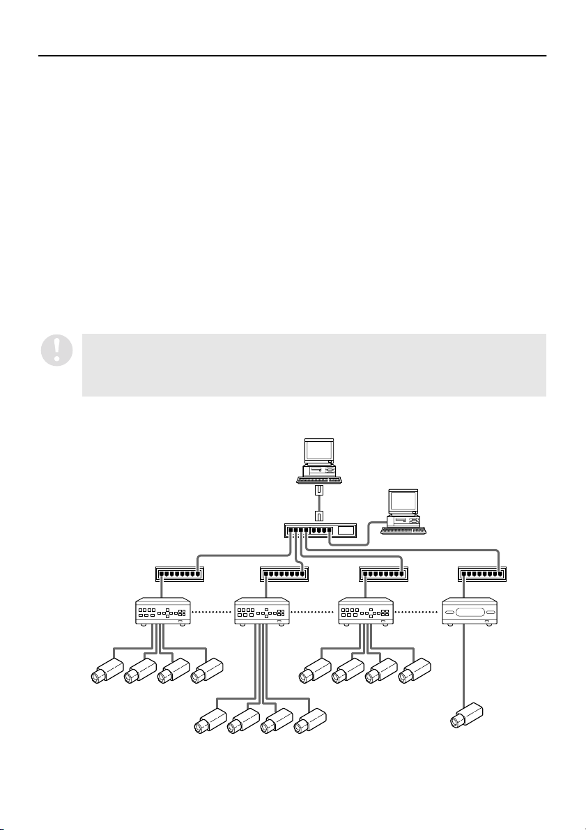
NETWORK CONFIGURATION
This system consists of DVRs, monitoring cameras and computer terminals that are used for remote
monitoring. All devices in the system are connected through a dedicated local area network (LAN).
●
Applicable models:
DSR-M800/DSR-M800P/DSR-M800PA/DSR-M804/DSR-M804P/DSR-M810/DSR-M810P
See “http://www.sanyosecurity.com” for models other than the above.
Network configurations can include a combination of different models.
●
Number of DVR connections:
When using automatic setting mode for IP addresses: Max. 1000 DVRs
(Up to 4000 DVRs can be connected depending on the subnet mask values.)
When using manual setting mode for IP addresses: Max. 250 DVRs
●
Number of computer terminal connections:
Max. 8 computers (1 master computer + 7 slave computers)
●
Applicable software:
If using this software (VA-SW814 or VA-SW81LITE) on the master computer, then the slave
computers must also be running the same version of software. Older versions of the software
(VA-SW800/804/80LITE) cannot be used with this software.
Slave computers that are running older versions of the software should be upgraded
by installing this software. Once the software upgrade has been carried out, you can
continue to use the same accessory hardware key as before (or enter the same serial
number that was entered before if not using a hardware key). (P.8)
Master computer
English
Slave computer
Switching Hub
Switching Hub
DVR1 DVR2 DVR3 DVR4
3
Page 5

NETWORK CONFIGURATION
● Examples of IP address setting ranges:
(When using automatic setting mode and the subnet mask is set to the standard 255.255.252.0)
Computer terminals: DVRs:
192.168.0.251 – 254
192.168.1.251 – 254
192.168.2.251 – 254
192.168.3.251 – 254
Distinction between “Master” and “Slave”
A master computer is a computer terminal that has operating privileges available for
registering and deleting DVRs that are connected to the network. The default setting is for one
master computer. In contrast, general computer terminals that do not have operating
privileges for registering and deleting DVRs are called slave computers, and a maximum of
seven of them can be connected. (P.20)
•
When using the software on a network, carry out the required network settings at the DVRs first.
IP addresses will be assigned automatically, but the “DVR NAME” and “GROUP” settings can
also be changed manually using a computer. (P.22)
•
You should make sure that the TCP/IP settings for the operating system (OS) that you are using
match the computers that are connected to the network. (P.6)
•
Connect the devices to an independent stand-alone network. Furthermore, check with the
network administrator to make sure that the IP addresses that you set do not conflict with IP
addresses that are already in use by the network.
192.168.0.1 – 250
192.168.1.1 – 250
192.168.2.1 – 250
192.168.3.1 – 250
4
English
Page 6
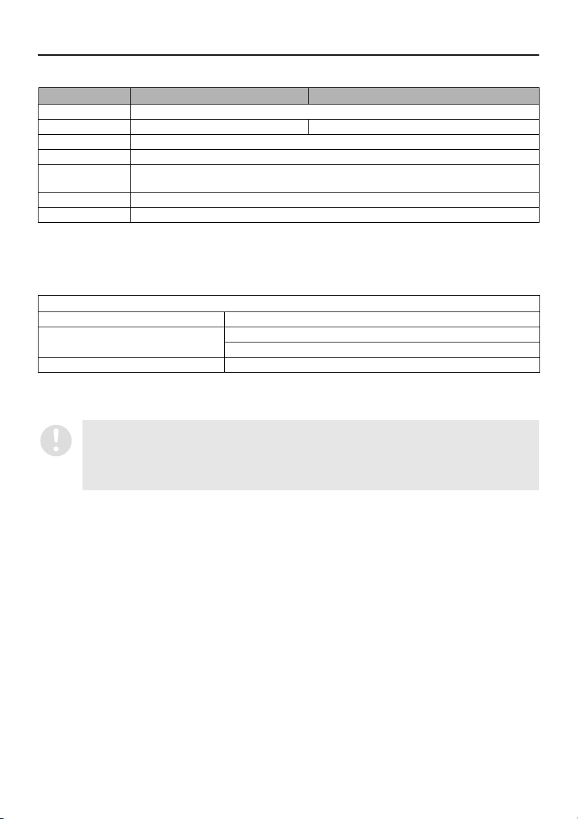
SYSTEM REQUIREMENTS
The following environment is required for the operation of this system.
Recommended Single Monitoring
System IBM PC/AT or Compatible
CPU Pentium 4, 3GHz or faster Pentium III 800MHz
Memory 256MB
Interface 100Base TX, USB (1.1)
Display XGA (1024 × 768 pixel), 16-million color or greater*1
Sound Sound card that supports 48 kHz stereo playback (PCI connection recommended)*3
OS Windows
*1 If using at a resolution of 1024x768, you will need to select “Auto-hide the taskbar” in the Taskbar Properties menu.
*2 Latest driver with 100% DirectX 9.0b compatibility is required.
*3 If no sound card is available, monitoring of DVR images and audio playback will not be possible when [AUDIO
RECORDING] is set to [ON].
Recommended graphics chip
ATI RADEON9000 series or later
nVidia GeForce4 series or later
Matrox MillenniumP series or later
®
Windows
Pentium
countries.
is a trademark, or registered trademark of Microsoft Corporation in the United States and/or other countries.
®
is a trademark or registered trademark of Intel Corporation or its subsidiaries in the United States and other
•
•
AGP graphics card for hardware overlay*2
®
XP Professional
Quadro4 series or later
The firewall function of some computers may cause the port that is required for communication
with the DVR to be isolated. If using the Windows XP firewall function or some other firewall
software, disable the operation of the firewall function.
If monitoring images that are distorted because of reasons such as an unstable sync signal, the
display may not appear normally even if the PC meets the above specifications.
English
5
Page 7
TCP/IP SETTINGS
TCP/IP (Transmission Control Protocol/Internet Protocol) is a standard protocol that is used for the
Internet and intranets. When using the software on a network, you should first change the TCP/IP
settings as required in accordance with the operating systems (OS) of the various computers that on the
network that are to be used. (Operation is only guaranteed under Windows XP)
Click the Network Connections icon in
1
the Control Panel.
The “Network and Internet Connections”
window will be displayed.
Click “Local Area Connections”.
2
The “Network Connections” window will be
displayed, and the settings for the LAN card
(Ethernet adapter) being used will appear in
the “LAN or High-Speed Internet” column.
Right-click on the LAN card (Ethernet
3
adapter) being used, and then select
“Properties (R)” from the pop-up menu.
The “General” tab window in the “Local Area
Connection Properties” window will be
displayed.
Check that “Internet Protocol (TCP/IP)”
4
is selected in the list of components
used by the Ethernet board that appears
in the “This connection uses the
following items: (O)” box.
If “Internet Protocol (TCP/IP)” is not
selected, select it.
Click [Properties (R)].
5
The “General” tab window in the “Internet
Protocol (TCP/IP) Properties” window will
be displayed.
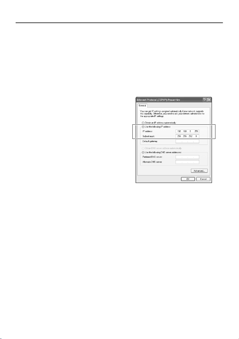
Select “Use the following IP address:”
6
and then type in the IP address and the
subnet mask.
For standard settings, enter a subnet mask
of “255.255.252.0” as shown in the example
illustration.
Check the settings, and then click [OK].
7
The display will return to the “Local Area
Connection Properties” window.
Click [OK].
8
This completes the TCP/IP settings.
6
English
Page 8
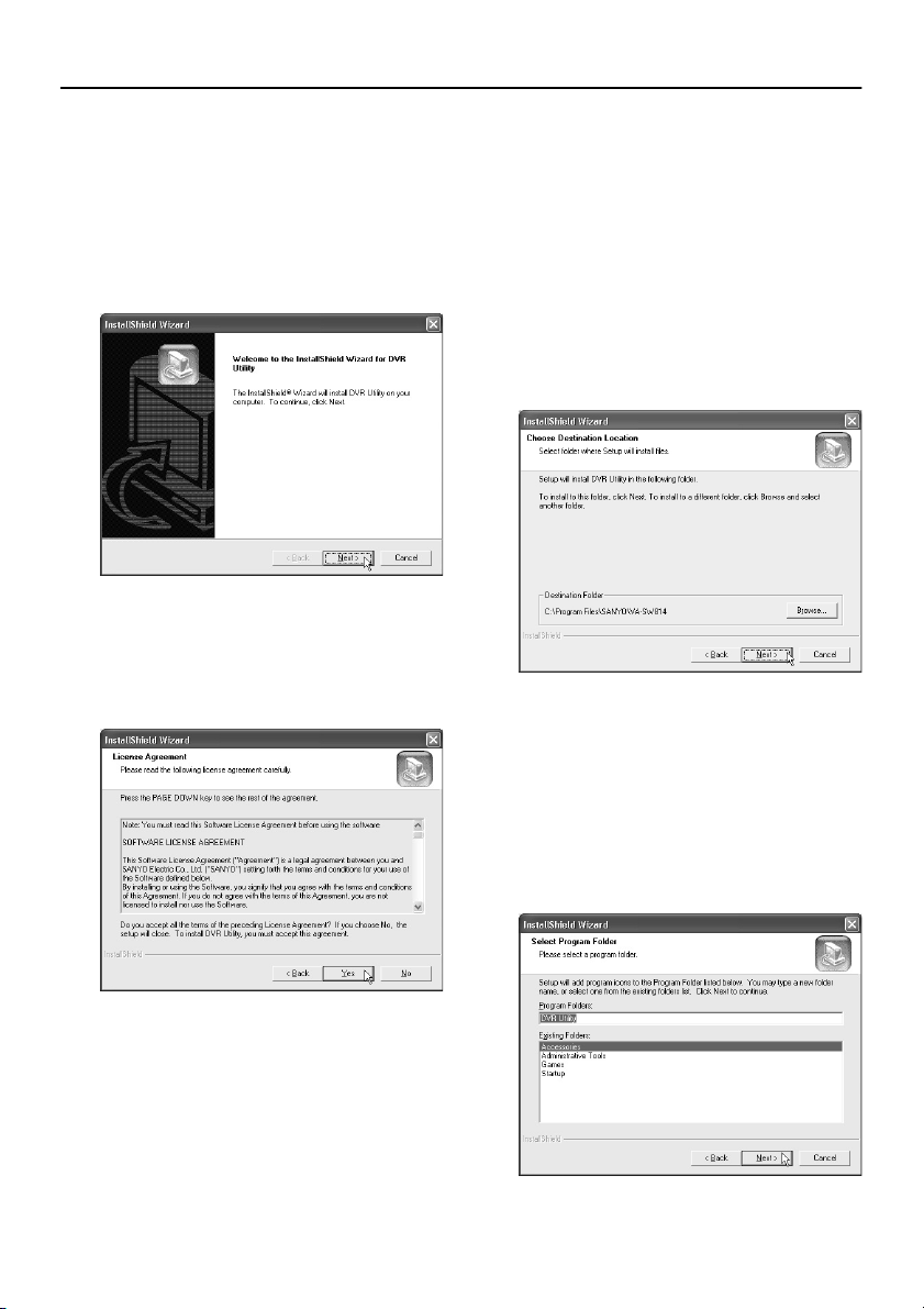
INSTALLING THE SOFTWARE
Install the DVR Utility Software to the computer that is connected to the network. The following
procedure will install the hardware key driver and the MP2 Viewer at the same time.
Insert the DVR Utility Software CD into
1
the CD-ROM drive of the computer.
The “Welcome” window appears.
Click [Next] in the “Welcome” window.
2
Click [Yes] in the “License Agreement”
3
window.
The License Agreement will be displayed.
Be sure to check the terms of the License
Agreement carefully.
Click [Next] in the “Choose Destination
4
Location” window.
Normally you should accept the default
location without changing it. If you would
like to change the destination folder for
installing the software, type the path to the
folder directly into the box, or click [Browse]
and select the folder to be used for the
installation.
Click [Next] in the “Select Program
5
Folder” window.
This lets you check the program folder
where the program icon will be added.
Normally you should accept the default
folder without changing it. If you would like
to change the program folder, type the
folder name into the box, or select an
existing folder from the list underneath.
English
7
Page 9
INSTALLING THE SOFTWARE
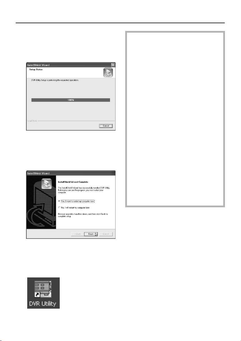
Installation will begin.
6
Installation of the software will begin, and a
progress bar showing the installation
progress will appear in the “Setup Status”
window.
Restart the computer.
7
Click [Finish] in the “InstallShield Wizard
Complete” window to restart the computer
automatically. Once the computer has
restarted, installation is then complete.
●
Version Updates
When updating the DVR Utility Software
from version VA-SW800/804 to
VA-SW814, you can follow the procedure
given below to reuse the DVR registration
list that was created by the VA-SW800/
804 version.
1
Uninstall version VA-SW800/804.
2
Install version VA-SW814.
3
Display the “SETUP” window, and
open the “REGISTER DVR” tab.
4
With the computer connected to the
LAN, select “MANUAL” for “TCP/IP
ADDR.”.
5
Click [CREATE LIST].
After a brief period, the DVR
registration list that was created by the
VA-SW800/804 version will be
regenerated and displayed.
6
Click [OK].
The list details will be stored on the
computer and applied to the DVRs.
8
Shortcut icon display
After restarting the computer, a shortcut
icon for the software will appear on the
desktop. Double-click the icon to start the
software.
Refer to “INITIAL SETUP (SETUP
WINDOW)” (P.20 – 25) for further details
on these operations.
8
English
Page 10

LOGGING IN/LOGGING OFF/DISPLAY
LANGUAGE SETTING
The user level for each user on the network can be set to one of four levels. The user level is verified by
means of the user name and password that are entered when the user logs in.
■ User Level
Different operating privileges are set for each user level. The range of operations that are permitted to
be carried out by users depends on their user level. Set the user levels in accordance with the operating
environment.
User Level ID1 ID2 ID3 ID4
Username (Default setting) ID1 ID2 ID3 ID4
Monitoring live images DVR selection, volume adjustment, etc.
Playback operations
Search operations Time/date search
Saving operations Saving still images
Recording operations Normal recording
Default settings Language, TV system, master computer,
Clock and system
update settings
Menu settings DVR monitor language, daylight saving
Broadcast transmission
settings *
Tamper detection Checking for image tampering
* VA-SW81LITE has restricted operation for some functions.
Operations marked with Ç are limited to the master computer.
Operation limit levels in brackets can be set using the SYSTEM SETUP tab in the “SETUP” window. (P.21)
Password (Default setting) 1111 2222 3333 4444
mmmm
mmm
mmm
Alarm search
Alarm thumbnail search
mmm
mmm
mmm
Download
Timer download *
(m)(m) m
(m)(m) m
mm
Timer recording
download operation limit, automatic clock
adjustment and sequence interval settings
Registering and deleting DVRs
Network connection expansion
User registration, changing and deletion
Clock settings
Firmware updates
System-related information display
time, external clock and remote operation
condition settings
Recording condition setting
Timer recording
Holiday settings
Display information and warning buzzer
settings
Monitoring window settings
Motion sensor and camera title settings
Normal recording, timer recording
Menu upload, clock set, system update
mm
m
Ç
m
Ç
m
m
m
m
m
m
m
m
m
m
mm
m
mmm
English
9
Page 11
LOGGING IN/LOGGING OFF/DISPLAY LANGUAGE SETTING
■ Logging In
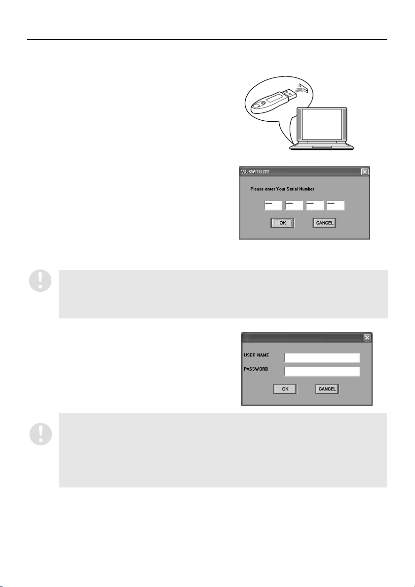
Hardware key installation
1
Insert the accessory hardware key into the USB
port of the computer.
If the hardware key is not installed, the software
will operate as the Lite version, and some
functions will be disabled. (P.9, 12)
Serial No. input (VA-SW81LITE)
2
When the software is run for the first time after
installation, the serial number input dialog box will
be displayed. Type in the specified serial number.
If the hardware key is installed, the serial number
dialog box will not be displayed again the next
time the software is run.
However, the serial number must be typed in at
the following times.
When the hardware key is not installed
•
When running VA-SW81LITE (limited function
•
version)
If the number entered does not satisfy the checksum conditions, the input dialog box will be
displayed again. If an incorrect serial number is typed in three times in succession,
“AUTHENTICATION ERROR” will be displayed and the only available operation will be to exit (log
off).
The serial No. is listed on the label that is affixed to the pocket of the VA-SW81LITE CD-ROM disk.
Authentication check
3
When the software is run, the window for entering
the user name and the password will be displayed.
When logging in, type your user name into the
“USER NAME” box and type the password for
verification into the “PASSWORD” box. Then click
[OK] or press the [ENTER] key.
•
The first time the master computer is started up, log in by entering the initial settings for user
level ID4 (username: ID4/password: 4444). (P. 9)
•
If the password typed in is incorrect, the window for entering the user name and the password
will be displayed again and you will need to type the password in once more. In addition, if you
click a button to use an operation that is not permitted by the user level that you have logged in
at, the window for entering the user name and the password will be displayed again and you will
be required to type in the user name and password corresponding to the user level for that
operation.
10
English
Page 12
LOGGING IN/LOGGING OFF/DISPLAY LANGUAGE SETTING
■ Logging Off
Click on the toolbar to close the connection.
Make sure that you carry out this disconnect operation when exiting the software and closing the
program window.
■ Display Language Setting
This software uses English as its default display language. However, you can use the SYSTEM SETUP
tab in the “SETUP” window to set the display language to any one of the following five languages. (P.20)
When using the software, first change the display
language setting to the required language.
Available languages:
English, French, Spanish, German, Chinese
After you have changed the setting, restart the
application. The displays will then appear in the newly
selected language.
To display text in Chinese, select “Install files
for East Asian languages” in “Regional and
Language Options” in the Control Panel.
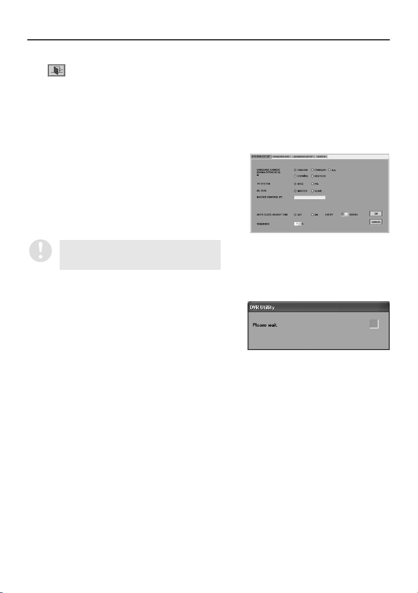
■ Display While Communication is in Progress
When a screen operation has been carried out that
requires the system to wait for a response from the
DVR, the following message box will be displayed and
the green indicator will flash.
The message box will disappear once communication
is complete (or a communication error or other error) is
generated.
English
11
Page 13
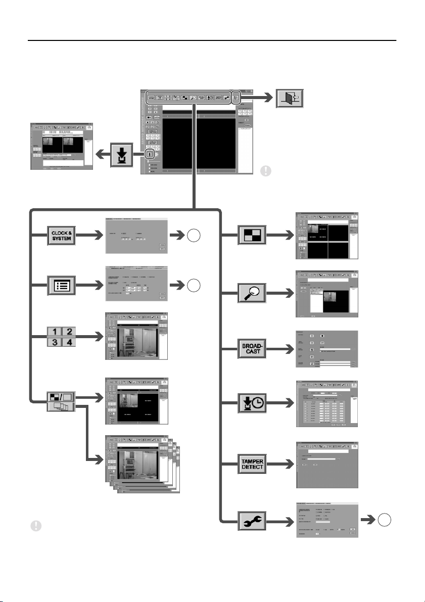
BASIC WINDOW FLOWCHART
When the software is started and a user has logged in, the main window for live image monitoring and
recording/playback is displayed. The software lets you display a variety of operating windows and
setting windows starting from the main window, as shown in the flowchart diagram below.
Click to exit the
software and
close the program
window
Download window
B
(P. 17)
CLOCK & SYSTEM window
C
(P. 18)
MENU window
INDIVIDUAL CAMERA window
(DSR-M804 only)
QUAD/SINGLE window
✱
✱
✱
If the hardware key is not
installed, control buttons
marked with ✱ will not be
displayed.
MULTI window
ALARM SEARCH window
BROADCAST window
TIMER DOWNLOAD window
SEQUENCE window
(DSR-M804 only)
The sample windows shown in this instruction manual
are all examples of windows that appear when using a
4-channel type DVR (DSR-M804).
12
TAMPER DETECTION window
A
(P. 16)
SETUP window
English
Page 14
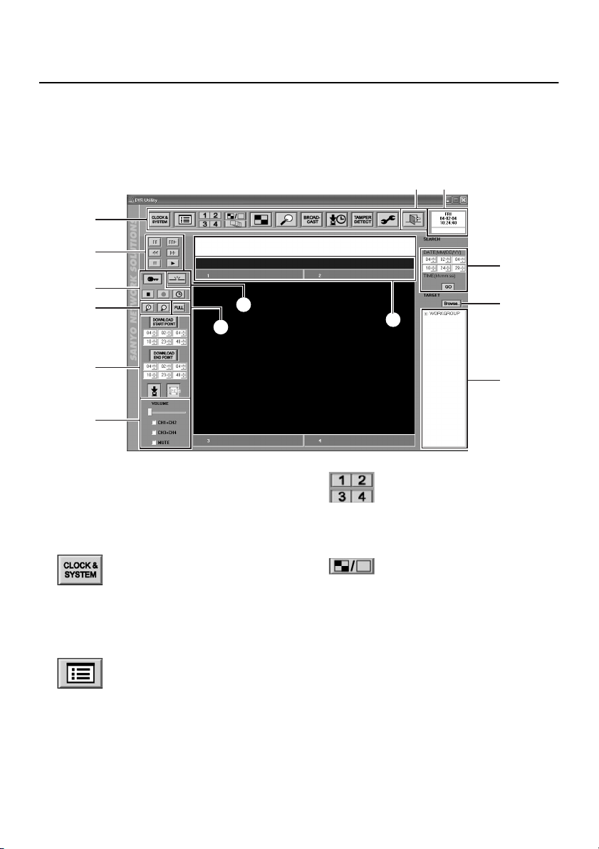
FUNCTIONS OF EACH MAIN WINDOW (MONITORING,
RECORDING AND PLAYBACK WINDOW) COMPONENT
The main window is the initial window that is displayed the first time the software is run. This is the basic
window for carrying out live image monitoring and recording and playback operations, and it can also be
used as the starting place for displaying other setting windows. The toolbar that appears at the top of
the window appears in the same way for all windows, except when the login window is displayed at
startup.
2 3
1
5
6
8
7
9
F
G
1
Toolbar
This lets you use basic functions and open
different setting windows with a single click.
Click the required icon to use a function or
window.
●
This displays the “CLOCK & SYSTEM”
window.
Used for clock setting, firmware updating and
checking system-related information.
●
This displays the “MENU” window.
This window is used to carry out menu
settings such as setting recording
parameters.
CLOCK & SYSTEM (P.34)
MENU (P.39)
4
K
●
If the DVR is a DSR-M804 (4-channel type),
images from the specified camera are
displayed in a single screen.
●
This is the initial screen that is displayed after
the software is started. Images from all
channels from the specified DVR are
displayed in a single screen. The screen
configuration changes depending on the type
of DVR.
DSR-M804 (4-channel type): Quad screen
DSR-M800/M810 (1-channel type): Single
screen
INDIVIDUAL CAMERA (P.54)
QUAD/SINGLE (P.54)
H
I
J
English
13
Page 15
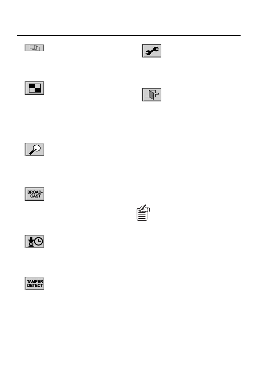
FUNCTIONS OF EACH MAIN WINDOW (MONITORING, RECORDING AND
PLAYBACK WINDOW) COMPONENT
●
If the DVR is a DSR-M804 (4-channel type),
all images from the specified camera are
displayed in sequence with automatic
switching.
●
Images from a maximum of four DVRs are
allocated to windows in a 4-screen split
screen, so that images from all connected
cameras are displayed in a single multi
screen. If all of the DVRs are DSR-M804
models (4-channel type), 16 screens are
displayed.
●
This displays the “ALARM SEARCH” or
“ALARM THUMBNAIL SEARCH” window.
This window is used to search for alarm
recordings.
●
This displays the “BROADCAST” window.
This window is used for issuing batches of
basic commands such as commands to start
or stop recording to the DVRs that are
connected to the system.
●
This displays the “TIMER DOWNLOAD”
window.
Timer reservations can be made for
downloading recorded images.
SEQUENCE (P.57)
MULTI (P.54)
ALARM SEARCH (P.70)
BROADCAST (P.52)
TIMER DOWNLOAD (P.81)
●
This displays the “SETUP” window.
This window is used to make initial
program settings after the software has
been installed.
2
Click to exit the software and close the
program window
3
Date and time display
This shows the date and time set by the
computer’s internal clock.
The timer download status is displayed
underneath the date and time. (P.84)
4
Message display window
Results for details such as error and alarm
status and setting operations are displayed in
sequential messages.
<DVR registration name, date and time of
occurrence, details of occurrence>
Display example:
DVR-3 11-05-04 15:45:40 LIVE ERROR
BROADCAST 11-05-04 15:50:20 DONE
SETUP (P.20)
EXIT
•
The only error messages that are
displayed are system errors such as
communication errors.
•
When the software is exited, the
information is discarded from the
display, but it can still be found in the
log file that is saved in the log file
sub-folder of the folder that the software
has been installed into.
(C:\ProgramFiles\SANYO\VA-SW814\log)
●
This displays the “TAMPER DETECT”
window.
This window lets you determine if any
tampering has been carried out on recorded
images.
TAMPER DETECT (P.89)
14
English
Page 16
FUNCTIONS OF EACH MAIN WINDOW (MONITORING, RECORDING AND
PLAYBACK WINDOW) COMPONENT
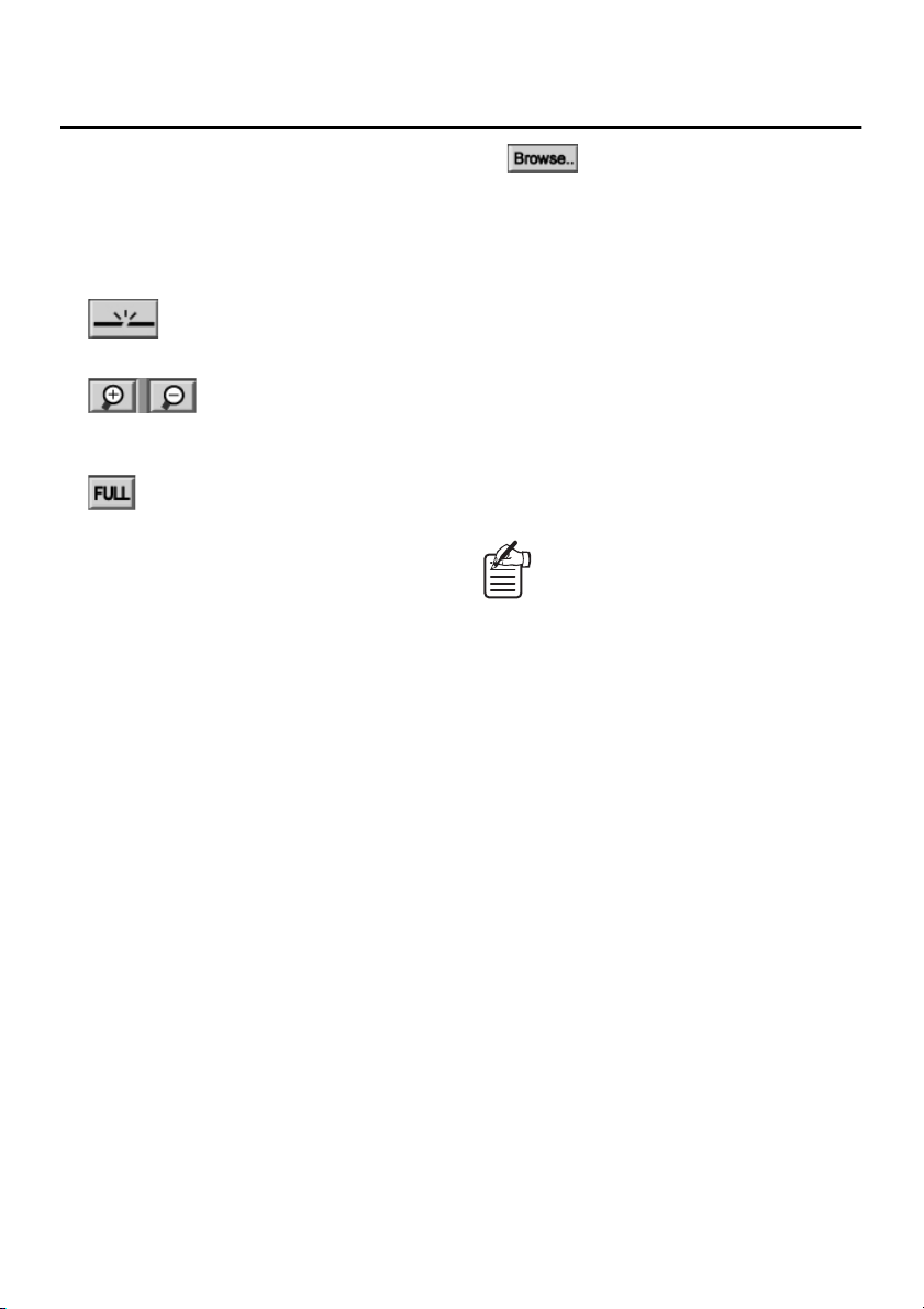
5
Playback control panel (P.69)
This is used when playing back recorded
images.
6
Recording control panel (P.64 – 66)
Use when manually recording the monitored
images.
7
This breaks the connection to a DVR.
8
This enlarges live or playback images
centering on a specified point in the screen.
9
This hides the toolbar and control panel so
they do not appear on the screen, and
displays the current image so that it fills the
whole of the screen area.
F
Saving control panel (P.74, 75)
Saves still images and downloads recorded
images.
G
Audio adjustment panel (P.63)
Audio output items such as volume, channel
selection and muting can be adjusted for both
live and recorded images.
H
Time/date search (P.70)
This lets you play back recorded images by
specifying the date and time that they were
recorded.
Disconnect DVR (P.63)
Zoom (P.59)
Full screen (P.60)
I
Click this button to specify files that are saved
on a computer drive. Folders and files can be
viewed in a list, and you can specify a file by
typing its filename into the window.
The only types of file that can be viewed are
files in MP2 format that have been
downloaded from a DSR-M800/M804/M810
series. Files that have been saved in JPEG
format cannot be viewed.
J
TARGET
The DVR names and attribute group names
that are recorded by the computer are
displayed in a tree list in the window. Menu
settings and monitoring, recording and
playback operations can be carried out by
clicking a DVR name in the list to specify a
DVR.
K
Title bar (P.58)
Image information is displayed on the bar in a
two-level structure for DVRs and for cameras.
When a multi screen is displayed, a window
can be selected by clicking on its title bar.
Browse
If you click the “+” symbol at the left of a
group, the DVRs that have been registered
in the group will be displayed, and the “+”
will change to a “–”. If you click the “–”
symbol, the list of DVRs will disappear and
the symbol will change back to a “+”.
English
15
Page 17
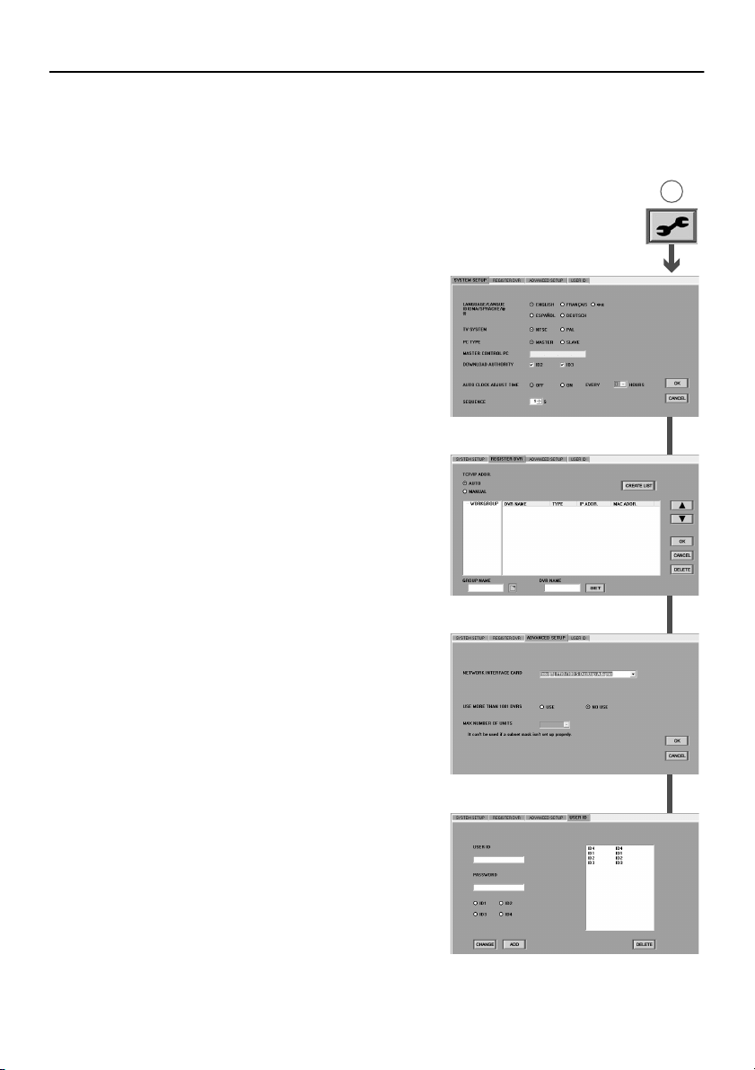
BASIC NETWORK SETTINGS
In order to use a computer to control DVRs that are on the network, you first need to set some basic
network-related system conditions. Click the icons on the toolbar in the main window to display the
respective setting windows, click on the tab indexes to specify a particular setting menu, and use these
setting menus to make the settings.
(User Level: ID4)
■ Initial Setup: SETUP Window (P.20)
This window contains the following four tabs. They are
used to carry out initial settings relating to the network
configuration and the system environment.
1
SYSTEM SETUP tab
Display language setting
•
Setting the TV format (NTSC/PAL) in accordance
•
with the input signals
Setting the master computer address
•
Download operation limit level setting
•
Setting the automatic adjustment function for DVR
•
clocks
Sequence screen switching interval setting
•
2
REGISTER DVR tab
(Operation only possible at master computer)
The options in this tab let you add and remove DVRs on
the network from the DVR registration list. In addition, it
can be used to list the properties of each registered
DVR.
3
ADVANCED SETUP tab
This lets you expand the network so that 1001 or more
DVRs can be connected to the same network.
4
USER ID tab
(Operation only possible at master computer)
This is used to register, change and delete users that
can log into the system.
A
1SYSTEM SETUP tab
2REGISTER DVR tab
16
3ADVANCED SETUP tab
4USER ID tab
English
Page 18
BASIC NETWORK SETTINGS (User Level: ID4)
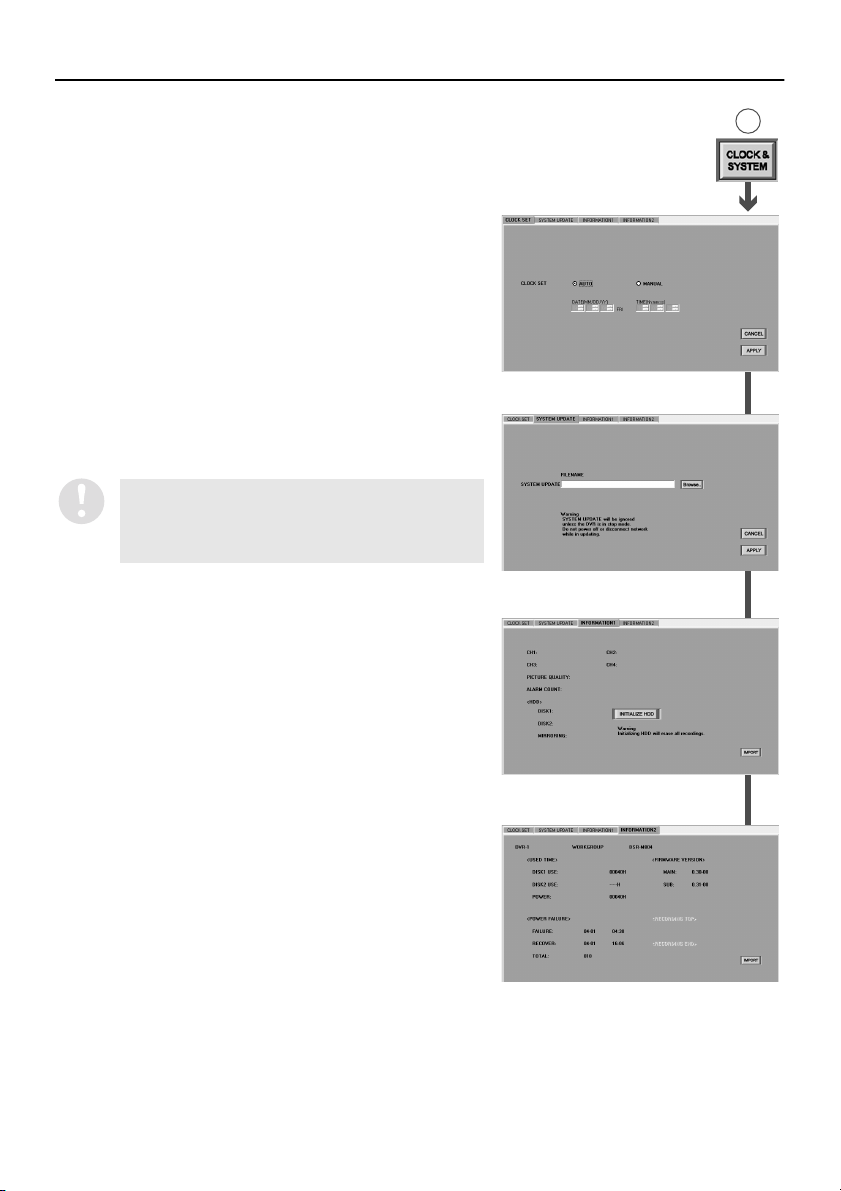
■ Clock Settings and System Updates:
CLOCK & SYSTEM Window (P.34)
This consists of the following four types of tabs which can
be used for operations such as setting the clock, updating
the firmware and displaying system information.
1
CLOCK SET tab
This is used to set the current time for selected DVRs.
2
SYSTEM UPDATE tab
This is used to update the firmware for selected DVRs.
3
INFORMATION1 tab
This is used to display DVR setting information and
information about the hard disk, and is also used for
hard disk initialization.
4
INFORMATION2 tab
This shows information such as the DVR usage time,
power outages and the firmware version.
•
For the DSR-M810, the first and last recording
dates and times are also displayed.
•
With the DSR-M800, the firmware version is not
displayed.
B
1CLOCK SET tab
2SYSTEM UPDATE tab
English
3 INFORMATION1 tab
4 INFORMATION2 tab
17
Page 19
BASIC NETWORK SETTINGS (User Level: ID4)
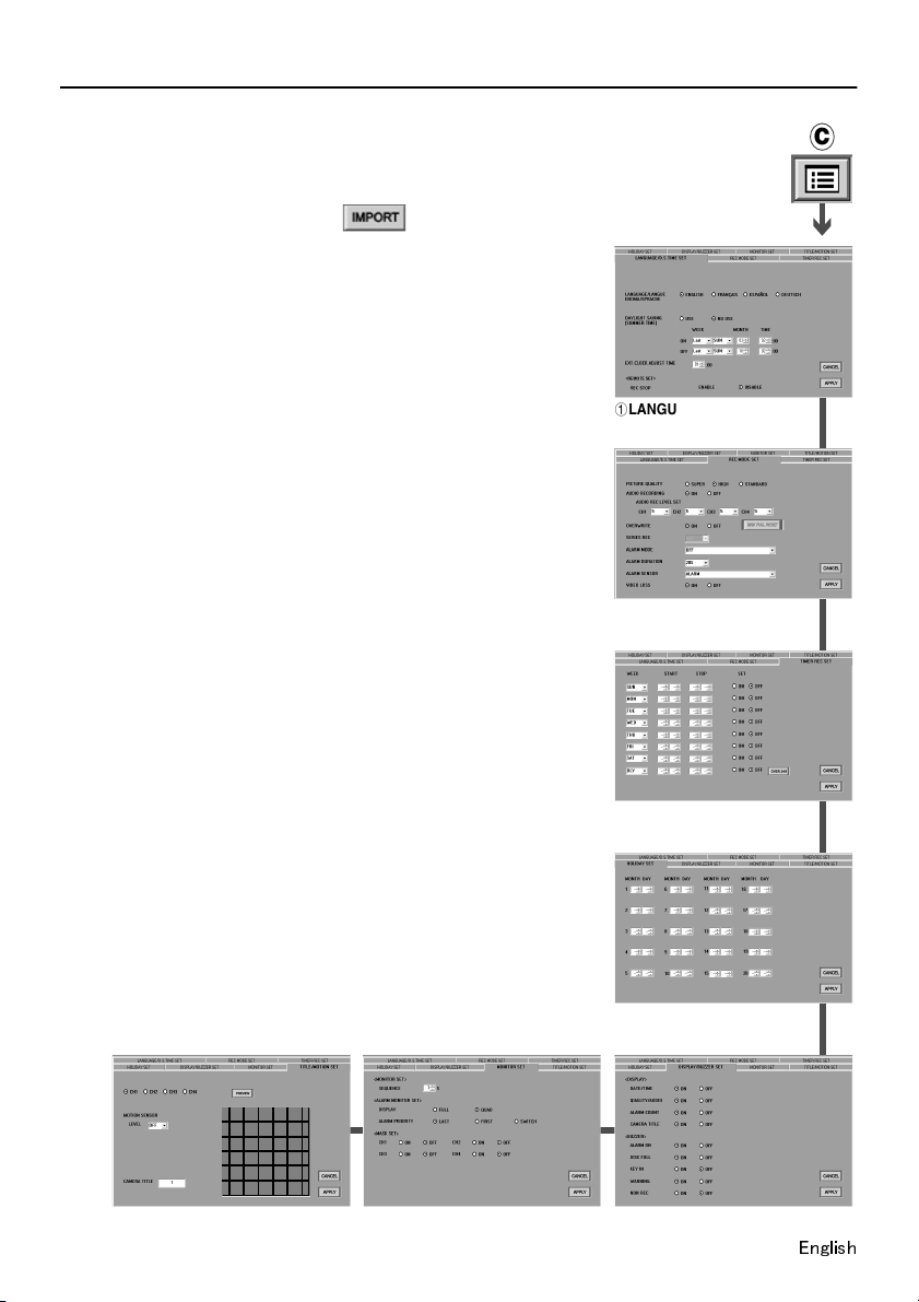
■ Menu Settings: MENU Window (P.39)
This window contains the following seven tabs. They are used to
carry out operations such as setting recording conditions and setup
environments for selected DVRs.
If you specify a DVR and then click in the “MENU”
window, or if you double-click the name of a DVR and carry out the
selection operations given in the dialogue box, the information for
the selected DVR will be loaded and the window will become active.
1
LANGUAGE/D.S.TIME SET tab
This is used to make settings such as the display language for
the monitor connected to the DVR, daylight saving settings, and
also lets you adjust the time for connected peripheral devices.
(With the DSR-M810, the “REMOTE SET” settings can also be
carried out.)
2
REC MODE SET tab
This is used to set the recording conditions for DVRs.
3
TIMER REC SET tab
This is used to set timer recording conditions for DVRs.
4
HOLIDAY SET tab
This is used to set holiday settings.
5
DISPLAY/BUZZER SET tab
This is used to set the display information for the monitor
connected to the DVR, and also lets you make warning buzzer
settings.
6
MONITOR SET tab (DSR-M804 only)
This is used for monitor window settings at the DVR
7
TITLE/MOTION SET tab (DSR-M804 only)
This sets the motion sensor and camera title settings for each
DVR channel.
C
1LANGUAGE/
D.S. TIME SET tab
2REC MODE SET tab
3TIMER REC SET
tab
4HOLIDAY SET tab
6MONITOR SET tab7TITLE/MOTION SET tab
18
5DISPLAY/BUZZER SET tab
Page 20
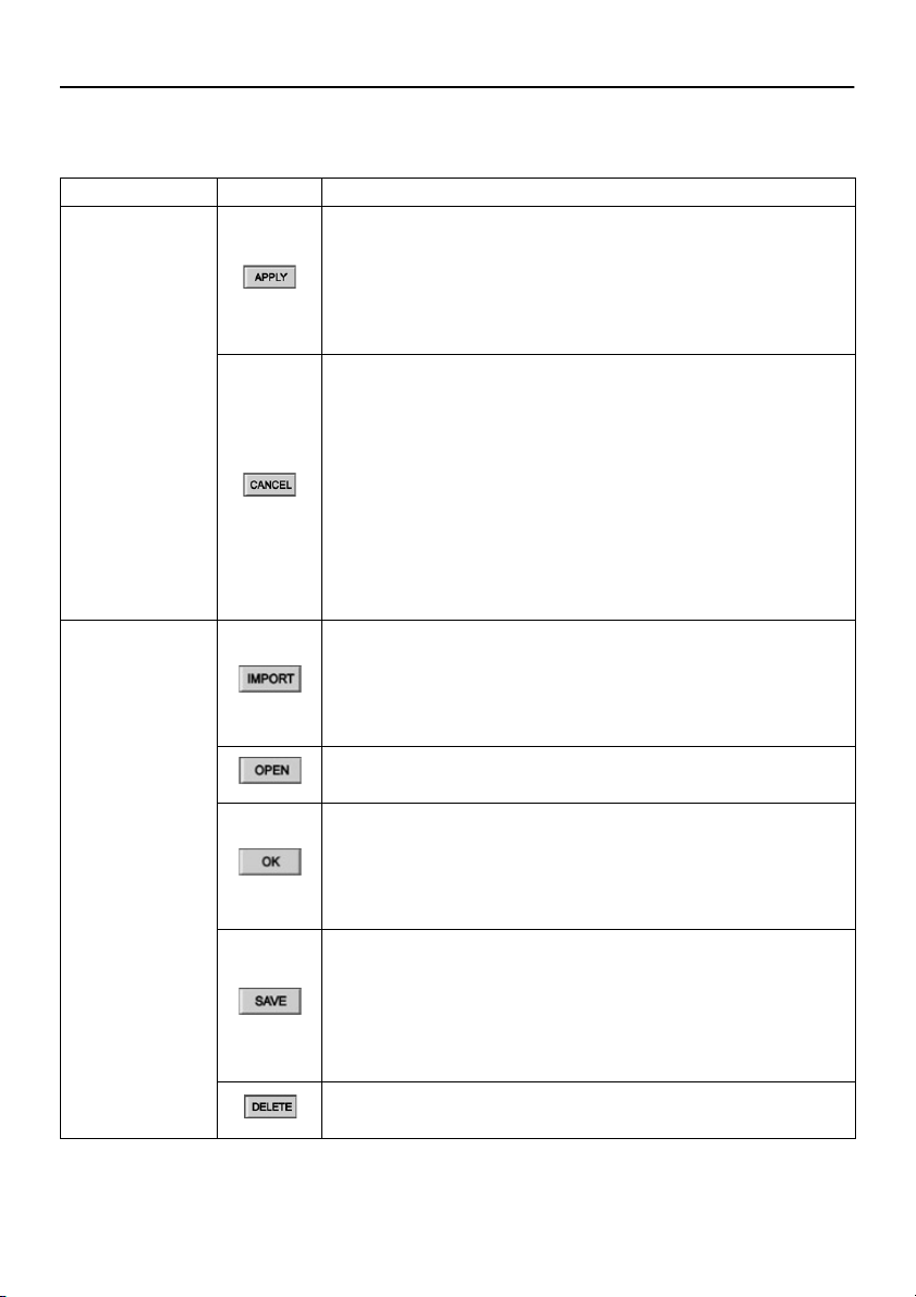
OPERATION OF SETTING BUTTONS
The following operation buttons are displayed in the various setting windows such as the initial setting
and menu setting windows. The basic functions of each button are the same for each window.
Button Button function and related operations
Table setting Tab input data is saved, but it is not sent to the DVR.
When a button is clicked, the setting data is checked, and if an
•
error is found, an error message is displayed.
If the data has been saved correctly, the tab index changes to
•
yellow and a message will be displayed saying that the unit is
ready to upload to the DVR. (Menu setting)
Cancels input and setting data.
If [APPLY] has not been clicked yet, the input data will be
•
canceled.
If [APPLY] has already been clicked, the original setting values
•
can be restored by clicking the [CANCEL] button and then using
[IMPORT] or [OPEN] to load the original data.
If an [IMPORT] or [OPEN] operation has not yet been carried
•
out, the values in the displayed tab will be returned to the
default settings.
If the tab index has changed to yellow, use the [CANCEL]
•
operation to return it to the normal color. (Menu setting)
Saving and
loading
This loads the current menu data from the selected DVR.
Menu data can also be loaded by double-clicking the DVR
•
name in the “TARGET” window.
If the tab index has changed to yellow, use the [IMPORT]
•
operation to return it to the normal color.
This loads the data that has been saved in the setting file on the
computer’s hard disk.
This uploads the setting data to a DVR.
For menu settings, the data that will be uploaded is the data for
•
tabs with indexes that are displayed in yellow.
After the data is uploaded, the tab indexes will return to their
•
normal color.
Saves the data being edited onto the hard disk of the computer.
The “Save as” dialog box will be displayed. Specify the
•
destination folder and filename and then click [SAVE].
File format: DSR-M800/M804/M810 Series Setup File (*.hbc)
•
If carrying out a menu upload from the “BROADCAST” window,
•
save the menu data first.
Clears a DVR registration (only displayed for the REGISTER DVR
tab).
English
19
Page 21
INITIAL SETUP (SETUP WINDOW)
The “SETUP” window is the first window that is displayed after the software has been installed.
It contains four tabs which are used to register DVRs that are to be connected to the network and to
make initial settings relating to the system environment. Click on the toolbar to display the
“SETUP” window, and then click a tab index to specify a tab.
(User Level: ID4)
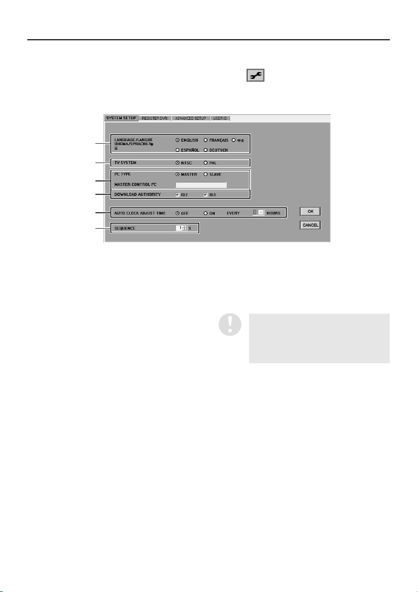
■ SYSTEM SETUP tab
1
2
3
4
5
6
1
LANGUAGE (Default setting: ENGLISH)
This sets the language that the software uses
for displays. Select the button corresponding
to the required language and then click [OK].
Available settings:
English, French, Spanish, German, Chinese
2
TV SYSTEM (Default setting: NTSC)
This sets the TV format (NTSC/PAL) in
accordance with the input signals. Select a
button and then click [OK].
3
PC TYPE/MASTER CONTROL PC
Select the type of computer being used and
then click [OK].
Available settings:
•
MASTER (Master computer):
This is the computer that has all operation
privileges available, including registering
and deleting DVRs that are connected to
the network. Only one master computer
can be set for each system. You do not
need to enter anything in “MASTER
CONTROL PC”.
•
SLAVE (Slave computer):
This is a computer for general users. If you
select “SLAVE”, you must be sure to enter
the IP address for the master computer in
“MASTER CONTROL PC”.
If you select the “SLAVE” setting and
then click [OK] without entering the IP
address in “MASTER CONTROL PC”,
then “IP ADDRESS ERROR” will be
displayed.
20
English
Page 22

INITIAL SETUP (SETUP WINDOW) (User Level: ID4)
4
DOWNLOAD AUTHORITY
(Default setting: ID2, ID3)
This sets operation permissions for
downloading for user levels ID2 and ID3.
Select the check boxes for the user levels that
are to have permission granted, and then
click [OK].
If the mask function (the function
that prevents images from specified
channels from being displayed on
the monitor screen) has been set at
the main unit, images can still be
viewed at the time that they are being
downloaded. This setting is used to
restrict download operation
permissions in order to prevent
masked images from being viewed.
5
AUTO CLOCK ADJUST TIME
(Default setting: OFF)
This function is used to automatically adjust
the time for all DVRs to match the time set by
the computer’s clock. Use the button to select
“ON”, specify the adjustment interval, and
then click [OK]. The automatic clock
adjustment function will operate each time the
specified interval of time has passed.
Available settings: 1/2/3/6/12/24 hours
6
SEQUENCE (Default setting: 1)
When using sequence display (DSR-M804
only), use the spin buttons to set the display
time (screen switching time) for each channel.
Available settings: 1–30 seconds
● Refer to page 19 for explanations of the
setting buttons (OK/CANCEL).
If the settings are changed using the
menu in the SYSTEM SETUP tab, the
new settings will take effect after the
software is closed and then restarted.
English
This function is invalid if the time will be
switching to or from summer time within
the current hour.
21
Page 23
INITIAL SETUP (SETUP WINDOW) (User Level: ID4)
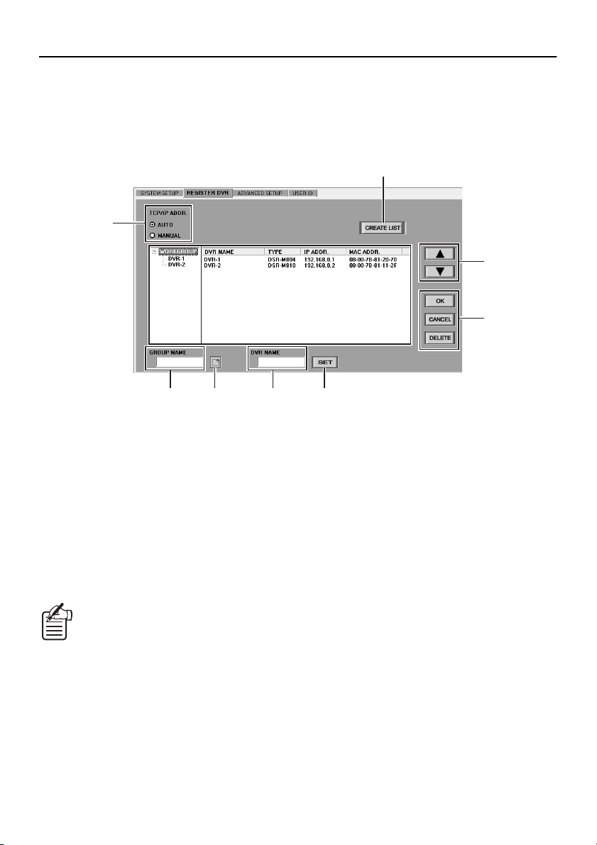
■ REGISTER DVR tab (Operation only possible at master computer)
The operations in this tab are limited to the master computer only. They let you register and delete
DVRs that are connected to the monitoring network. Slave computers obtain the registration information
by communicating with the master computer.
Names and functions of each window component
●
2
1
9
3
5 6 7 8
1
Address setting mode select buttons
(TCP/IP ADDR.)
These select the TCP/IP address setting
mode for the DVR.
Available settings: AUTO, MANUAL
2
Registration list creation button
(CREATE LIST)
This creates a new list for registering DVRs.
3
Tree list
This displays the group folders and the DVRs
that are assigned to them.
If you click the “+” symbol at the left of a
group, the DVRs that have been registered
in the group will be displayed, and the “+”
will change to a “–”. If you click the “–”
symbol, the list of DVRs will disappear and
the symbol will change back to a “+”.
4
F
4
DVR detail list
When you click on a group in the tree list, the
following details for the DVRs that are
assigned to that group will be displayed in list
form. You can change the group that a DVR is
assigned to, and also change the order of
display for group details.
•
DVR NAME:
The registered names of the DVRs (can be
changed).
•
TYPE:
The type of DVR is displayed automatically.
•
IP ADDR.:
The IP addresses for the DVRs are
displayed automatically. The addresses
can be set either automatically or manually.
•
MAC ADDR.:
The unique machine addresses for the
DVRs are displayed automatically.
22
English
Page 24
INITIAL SETUP (SETUP WINDOW) (User Level: ID4)
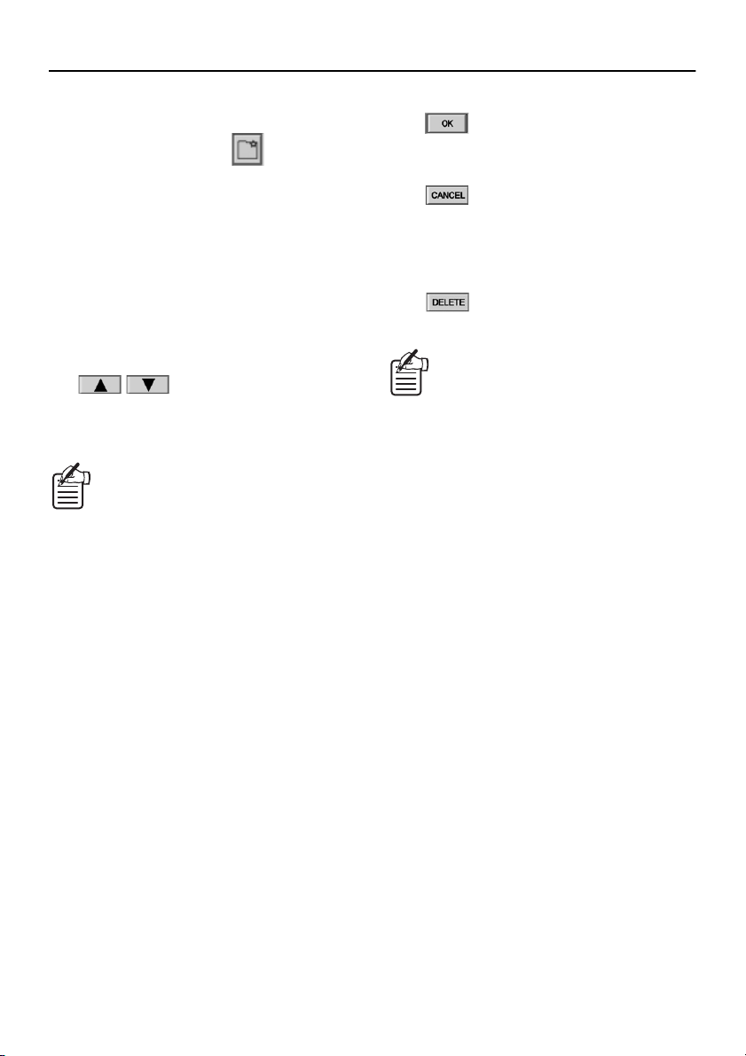
5
Group name entry box (GROUP NAME)
Enter the group name when creating a new
group.
6
Group creation button ( )
If you click this after entering a group name, a
new group is created in the registration list.
7
DVR name entry box (DVR NAME)
When changing the name of a DVR, enter the
new DVR name here.
8
DVR name setting button (SET)
If you click this after entering a DVR name,
the DVR name will be updated in the
registration list.
9
Display customization buttons
()
If you select a group or DVR and then click
these buttons, you can change the order of
display in the list.
You can also carry out this operation by
dragging and dropping.
F
Operation buttons
•
•
•
:
This saves the setting details into a file and
also applies them to the DVR.
:
If clicked before you click [OK], this
discards changes to the setting data and
returns the data to how it was before the
changes were made.
:
This deletes a DVR or group registration.
If you try to change to another window
after making changes to settings without
clicking [OK], a confirmation dialogue box
will be displayed, so select whether you
want the changed data to be saved or not.
English
23
Page 25
INITIAL SETUP (SETUP WINDOW) (User Level: ID4)
•
New DVR registration
●
In order to run the monitoring system, you first
need to register the DVRs that are to be
connected to the network.
There are two methods of registering DVRs: by
setting TCP/IP addresses using automatic mode,
or by using manual mode.
Automatic setting mode
A
If using standard settings, up to 1000 DVRs
can be registered. (Up to 4000 DVRs can be
connected depending on the subnet mask
values.)
Click the [AUTO] address setting mode
1
select button in the REGISTER DVR tab.
Automatic address setting mode will be
selected.
Click .
2
The buttons in the window will be locked
and creation of the registration list will start.
Hold down the [STILL] button on the
3
front panel of the connected DVR.
Keep pressing the button until the DVR's
built-in buzzer starts beeping.
If the buzzer starts making short
beeps and then changes to a long
beep, then an assignment error has
occurred. Check the network
settings and then repeat the
operation.
List registration
4
The address will be assigned automatically
and the following details will be displayed in
the registration list.
•
GROUP:
At the time of registration, a DVR is
initially assigned to the “WORKGROUP”
group. (This can be changed.)
DVR NAME:
At the time of registration, a name
consisting of the last digits of the MAC
address (XX-XX-XX) is assigned as the
DVR name. (This can be changed.)
•
TYPE:
Displayed automatically.
•
IP ADDR.:
Displayed automatically.
•
MAC ADDR.:
Displayed automatically.
●
If more than one DVR is being registered,
repeat the same operations for each DVR.
Click .
5
The buttons will be unlocked.
(The buttons will be unlocked automatically
after 10 seconds have passed since
creation of the list started, even if you do not
click again.)
Change the DVR name and assigned
6
group.
The initial DVR name and group that are
assigned at the time of registration are
provisionally assigned. You can change the
settings if you wish. These changes can be
made at any time.
•
DVR name:
Refer to “Changing DVR names”. (P.26)
•
Assigned group:
You can use drag and drop operations to
move registered DVRs to other groups.
Click .
7
The settings will be saved into a file and
they will also be applied to the DVRs.
24
English
Page 26
INITIAL SETUP (SETUP WINDOW) (User Level: ID4)
List registration
Manual setting mode
B
If the DVR configuration consists of a
mixture of DSR-M800/M804/M810 models,
up to a maximum of 250 DVRs can be
registered. If using only DSR-M810 models,
up to a maximum of 4000 DVRs can be
registered.
Click the [MANUAL] address setting
1
mode select button in the REGISTER
DVR tab.
Manual address setting mode will be
selected.
Enter the “IP ADDRESS” setting
2
manually in the “NETWORK SET”
settings for the DVR.
Enter a number from “001” to “250” as the
last three digits of the IP address.
4
The following details will be displayed in the
registration list.
•
GROUP
•
DVR NAME
•
TYPE
•
IP ADDR.
•
MAC ADDR.
If a group name already exists for a
DVR, that group name will be retained
automatically for the DVR when manual
setting is carried out. Because of this, if
a group with the same name already
exists in the tree list, the DVR will be
added to the bottom of the list for that
group. If a group with that name does
not already exist, a new group with the
registered name will be created in the
list.
The setting method for IP addresses
varies depending on the model of the
connected DVR (DSR-M800/M804/M810).
Refer to the instruction manual for the
DVR for details.
Click .
3
The buttons in the window will be locked
and creation of the registration list will start.
It takes approximately 10 seconds for the
list to be created.
●
Subsequent operations (steps 4 to 7) are
the same as for the automatic setting
mode. See P.24 for details.
Click .
5
The buttons will be unlocked.
Change the DVR name and assigned
6
group.
You can change the initial settings if you
wish.
Click .
7
This completes the address setting.
When setting addresses manually, be
careful not to duplicate the address
settings.
If you try to set an IP address that
has already been set for another
DVR, a duplication message will be
displayed. If you would like to
proceed with entering the
duplicated IP address, the DVR
which was previously registered
under that IP address will be
disconnected from the network and
the new DVR will be registered
instead.
English
25
Page 27
INITIAL SETUP (SETUP WINDOW) (User Level: ID4)
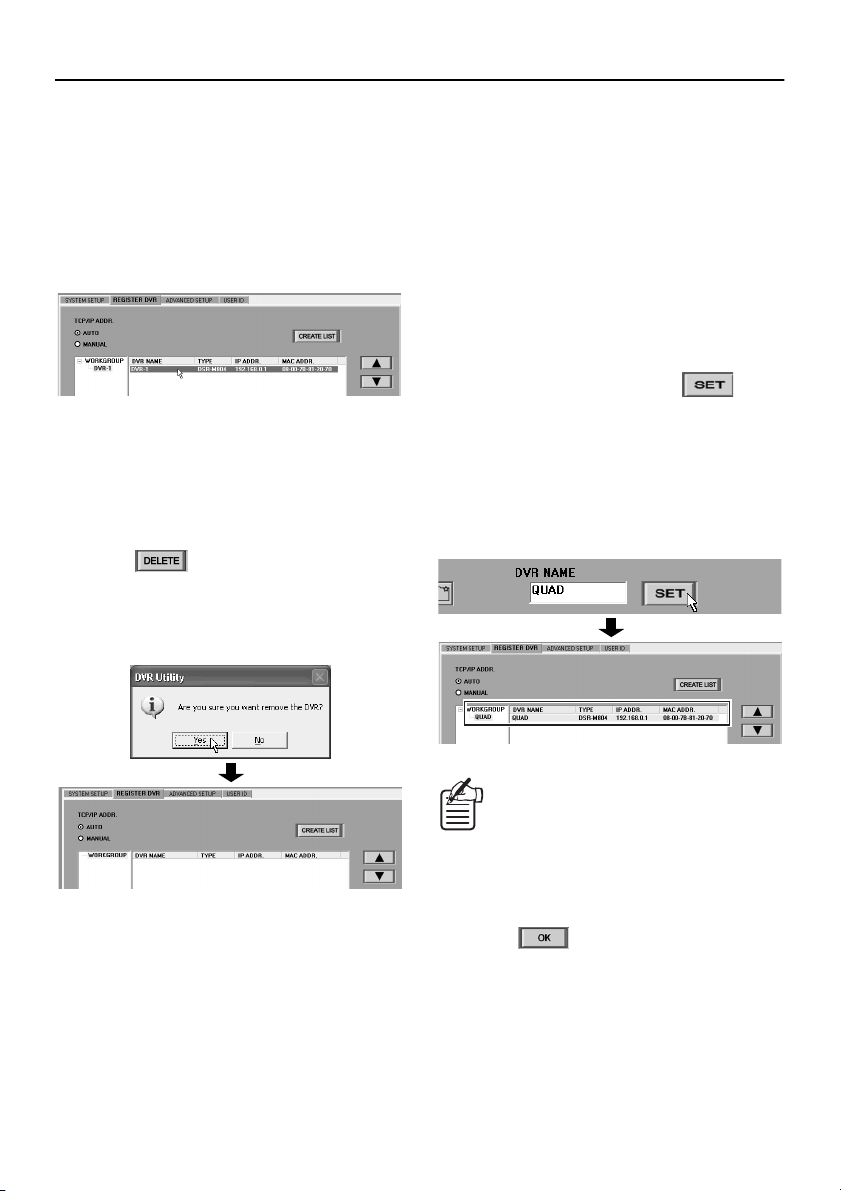
Deleting a DVR registration
●
Follow the procedure below to delete a DVR
registration.
Specify the DVR.
1
Click the DVR to be deleted in the tree list or
in the DVR detail list. (The entry in the tree
list will be highlighted in blue.)
Disconnect the connection cable.
2
Disconnect the connection cable from the
DVR that is to have its registration deleted.
If you try to delete the registration for a DVR
while the DVR is still connected to the
network, an error will occur.
Click .
3
A delete confirmation dialogue box will be
displayed, so click [Yes].
The registration for the DVR will be deleted
and it will be removed from the list.
Changing DVR names
●
At the time of registration, a name consisting of
the last digits of the MAC address (XX-XX-XX) is
assigned as the DVR name. You can change the
initial name to some other name by following the
procedure below.
Specify the DVR.
1
Click the DVR to be changed in the tree list
or in the DVR detail list. (The entry in the
tree list will be highlighted in blue.)
Enter the new DVR name in the “DVR
2
NAME” box, and then click .
You can use a combination of up to 10
uppercase alphabetic characters, numerals
and symbols (- : , / * (space)) in the DVR
name.
Once a new DVR name has been entered,
the name displayed in the registration list
will also be changed.
●
Repeat the above procedure to delete
registrations for other DVRs.
If you click once on the DVR name in the
tree list while the DVR is selected, you can
enter a new DVR name directly into the
list.
●
Repeat the above procedure to change the
names for other DVRs.
Click .
3
The setting details will be saved in the
computer and also applied to the DVRs.
26
English
Page 28
INITIAL SETUP (SETUP WINDOW) (User Level: ID4)
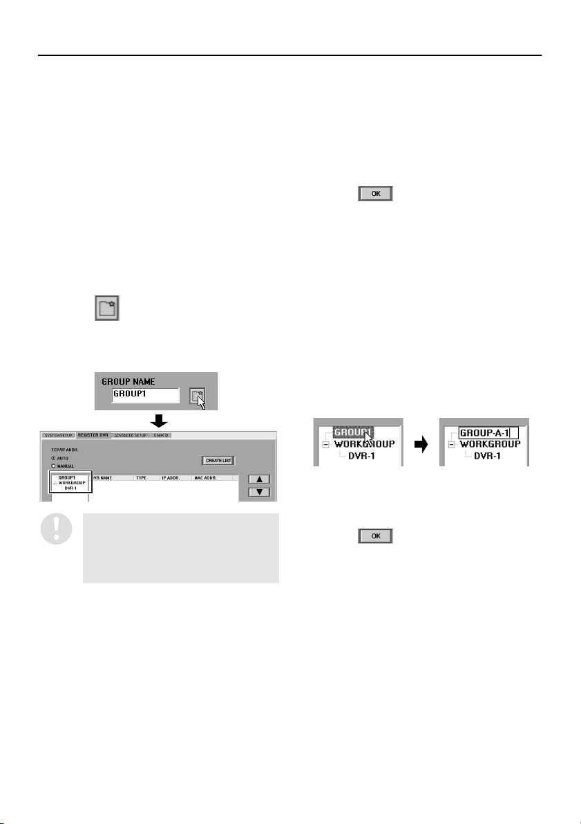
Change the DVR assignments to the new
Creating, changing and deleting
●
groups
A single group called “WORKGROUP” is use as
the initial group for assigning DVRs when they
are first registered. You can create new groups
and change the names of these groups
depending on your monitoring requirements.
Creating a new group
A
Enter the group name in the “GROUP
1
NAME” box.
You can use a combination of up to 10
uppercase alphabetic characters, numerals
and symbols (- : , / * (space)) in the group
name.
Click .
2
The new group will be added to the bottom
of the registration list (or above the
“WORKGROUP” group).
3
group.
You can move DVRs from other groups and
assign them to new groups by dragging and
dropping the DVRs from one group to
another. If a group exists with no DVRs
assigned to it, no new groups can be
registered.
Click .
4
The setting details will be saved in the
computer and also applied to the DVRs.
Changing a group name
B
Specify the group.
1
Click the group to be changed in the tree
list. The entry in the tree list will be
highlighted in blue.
Enter the new group name.
2
If you click once on the group name in the
tree list while the group is selected, you can
change the group name directly in the list.
If a group with the name entered already
exists, a dialogue box will be displayed
notifying you that the group already
exists, and the new group will not be
added.
●
Repeat the above procedure to add other
new groups.
English
●
Repeat the above procedure to change the
names of other groups.
Click .
3
The setting details will be saved in the
computer and also applied to the DVRs.
27
Page 29
INITIAL SETUP (SETUP WINDOW) (User Level: ID4)
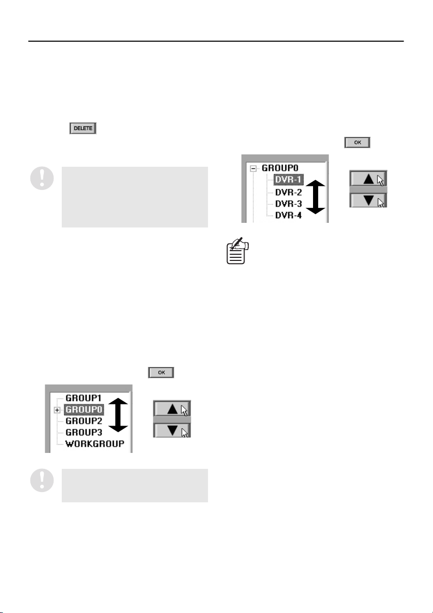
Deleting a group
C
Specify the group.
1
Click the group to be deleted in the tree list.
The entry in the tree list will be highlighted in
blue.
Click .
2
The specified group will be deleted from the
registration list.
Groups can only be deleted if there are
no DVRs assigned to them. If there are
any DVRs assigned to the group that
you would like to delete, change the
assignments for those DVRs to some
other group before deleting the group.
Customizing the list display
●
You can use the following operations to change
the display order for the list to any desired order.
Changing the group display order
A
You can select a group and then click j or l to
move the display for the selected group (and all
DVRs that are associated with that group) up or
down in the list. Alternatively, you can use drag
and drop operations to move the groups to any
desired position.
After making any changes, click .
Changing the DVR display order
B
You can select a DVR and then click j or l to
change the display order of the DVRs within the
group they are assigned to.
Alternatively, you can use drag and drop
operations to move the DVRs to any desired
position.
After making any changes, click .
If you select a DVR that is at the top of the
list within a group and then click
assignment for that DVR will be moved up
to the group that is above the current
group. Similarly, if you select the DVR that
is at the bottom of the list within a group
and then click
DVR will be moved down to the group that
is below the current group.
llll
, the assignment for that
jjjj
, the
The position of the “WORKGROUP”
group is fixed at the bottom of the list
and cannot be moved.
28
English
Page 30
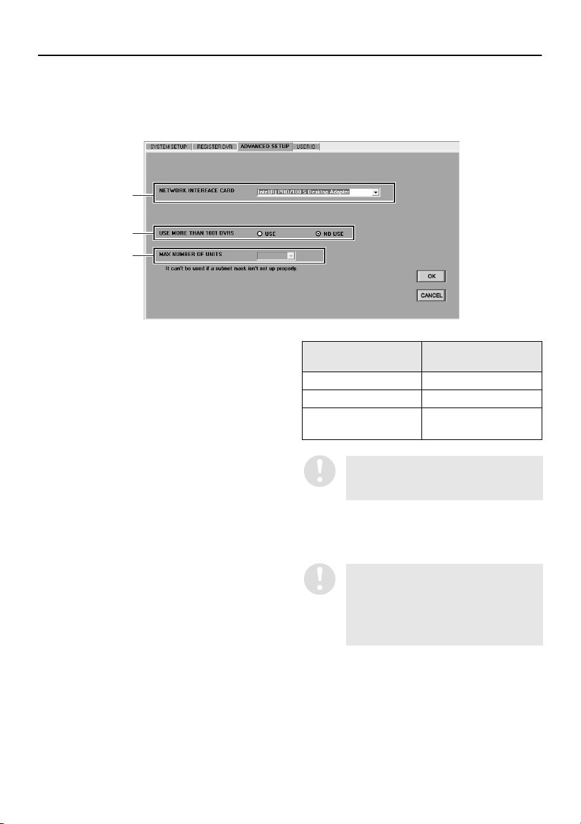
INITIAL SETUP (SETUP WINDOW) (User Level: ID4)
■ ADVANCED SETUP tab
The number of DVRs that can be connected in this system is initially set to a maximum of 1000 when
using standard specifications. However, if you would like to expand the network further, you can make
the following settings to increase the maximum number of DVRs that can be connected to 4000.
1
2
3
Specify the network interface card (NIC).
1
The NICs that are connected to the
computer are displayed in a drop-down list
box, so specify the NIC.
Specify the expansion mode.
2
Change the “USE MORE THAN 1001
DVRS” setting to “USE”.
•
USE: (Expanded mode)
When the number of DVRs to be
connected is more than 1001
•
NO USE: (Default setting)
When the number of DVRs to be
connected is 1000 or less
Specify the number of DVRs to be
3
connected.
When expanded mode (USE) has been
selected, the “MAX NUMBER OF UNITS”
setting can be selected. The number of
DVRs that can be connected in accordance
with the subnet mask setting are displayed
in a drop-down list box, so select the
number to be connected.
Subnet mask value
255.255.240.0 Max. 4000
255.255.248.0 Max. 2000
255.255.252.0,
255.255.255.0
In order for the system to operate
normally, select a subnet mask from one
of the four values given above.
Click [OK].
4
Up to the set number of DVRs can now be
connected.
Connections of up to 4000 DVRs is only
possible when the DVRs are DSR-M810
types. If DSR-M800 and DSR-M804 types
are intermixed, the maximum number of
DVRs that can be connected is only
1000.
Number of DVRs that
can be connected
Not expandable
(Max. 1000)
English
29
Page 31

INITIAL SETUP (SETUP WINDOW) (User Level: ID4)
■ USER ID tab (only available at master computer)
This is used to register, change and delete users who can log into the system. Up to a maximum of 32
users can be registered.
Names and functions of each window component
●
1 4
2
3
5
1
Username entry box (USER ID)
This sets the username for identifying a user
on the network.
2
Password entry box (PASSWORD)
This sets the password for authenticating a
user who is trying to log in.
3
User level setting buttons
These select the user level (operation
permission level). (P.9)
Available settings: ID1, ID2, ID3, ID4
4
List box
This shows a list of the usernames and user
levels for registered users.
Select users from this list when carrying out
operations such as changing and deleting
user registrations.
The default settings for user levels
ID1 to ID4 are initially displayed in
the list.
5
Operation buttons
•
•
•
:
Changes the registration details for a user.
:
Adds a new user registration.
:
Deletes an existing user registration.
30
English
Page 32

INITIAL SETUP (SETUP WINDOW) (User Level: ID4)
Registering a new user
●
When registering a new user, follow the procedure below to set the username, password and user level
(operation permission level).
1
5
2
3
4
Enter the username.
1
You can enter a username containing
between 1 and 16 alphanumeric characters
into the “USER ID” box. Usernames are
case-sensitive, and you can also use the
“ :./*” symbols and spaces.
The same username cannot be used
more than once.
Enter a password.
2
Enter a unique password for the user being
registered. The password can consist of
from 4 to 16 alphanumeric characters, and
passwords are case-sensitive. You can also
use the “ :./*” symbols.
Specify the user level.
3
Use the radio buttons to select the operation
permission level for the user being
registered. (P.9)
Available settings: ID1 – ID4
Click .
4
The password verification dialogue box will
be displayed.
Re-enter the password.
5
Re-enter the same password that was
entered in the “PASSWORD” box into the
“NEW” box, and then click [OK]. If the
password has been entered correctly, the
registration is then complete.
If an incorrect password is entered, an
error message will be displayed, so
re-enter the correct password.
English
31
Page 33

INITIAL SETUP (SETUP WINDOW) (User Level: ID4)
Changing a user registration
●
You can change an existing username, password or user level by the following procedure.
Specify the user registration to be
1
changed.
Click the user registration to be changed in
the list box to select it. The selected user
registration will be highlighted in blue, and
the current settings for that user registration
will be displayed in the respective boxes
and switches.
Change the registration details.
2
Follow the same steps as when registering
a new user to change the registration details
(username, password or user level).
Click .
3
•
If the username or user level has been
changed
The registration will be completed and the
list box display will also be updated.
•
If the password has been changed
The password verification dialogue box
will be displayed. Re-enter the current
password in the “CURRENT” box,
re-enter the new password into the
“NEW” box, and then click [OK]. If the
password has been entered correctly, the
registration is then complete, and the list
box display will be updated.
32
If an incorrect password is entered, an
error message will be displayed, so
re-enter the correct password.
English
Page 34

INITIAL SETUP (SETUP WINDOW) (User Level: ID4)
Deleting a user registration
●
Follow the procedure given below to delete a user registration.
Specify the user registration to be
1
deleted.
Click the user registration to be deleted in
the list box to select it. The selected user
registration will be highlighted in blue.
Click .
2
A delete confirmation dialogue box will be
displayed.
•
The operations in this tab can only be
carried out by users who are logged
in at user level ID4, but in addition to
this, adding, changing and deleting
registrations for ID4 user levels can
only be carried out at the master
computer.
•
The user ID and user level for the
default user ID (ID4) cannot be
changed, nor can this registration be
deleted.
Click [Yes].
3
The deletion will then be complete, and the
user registration will also be removed from
the list box display.
English
33
Page 35

CLOCK AND SYSTEM UPDATE SETTINGS
(User Level: ID4)
The “CLOCK & SYSTEM” window contains four tabs which can be used for tasks such as setting the
time, updating the firmware and displaying system-related information. Click on the menu bar to
display the setting window and then click a tab index to select a tab.
■ CLOCK SET tab
(Default setting: according to the computer’s internal clock)
Use the following procedure to set the current date and time for selected DVRs.
Click the “CLOCK SET” tab index.
1
The “CLOCK SET” tab window will be
displayed.
Select a DVR in the “TARGET” window.
2
The display color for the selected DVR will
change to blue.
Select the setting mode and then click
3
[APPLY].
•
AUTO (Default setting):
If you would like to set the date and
time for all connected DVRs in a
single batch operation in AUTO
mode, use the BROADCAST
function. (P.52)
•
MANUAL:
If “MANUAL” is selected as the setting
mode, the settings in the DATE and TIME
setting boxes can be changed manually.
Use the spin buttons to set the date
(DATE [MM/DD/YY]) and the time (TIME
[hh/mm/ss]), and then click [APPLY]. The
date and time that have been set will then
be applied to the DVR.
To cancel a date or time setting, click
[CANCEL] before clicking [APPLY]
•
Setting range: January 1, 2002 –
December 31, 2036
•
The date order will be according to
the Windows environment settings.
The date and time from the computer's
internal clock will be automatically applied
to the DVR.
34
English
Page 36

CLOCK AND SYSTEM UPDATE SETTINGS (User Level: ID4)
■ SYSTEM UPDATE tab
Use this tab window to specify a filename to use
for updating DVR firmware.
Click the “SYSTEM UPDATE” tab index.
1
The “SYSTEM UPDATE” tab window will be
displayed.
Select a DVR in the “TARGET” window.
2
The display color for the selected DVR will
change to blue.
Click [Browse..] (1111).
3
Reference files will be displayed in the
dialog box.
Specify the update file (Example:
4
ABCDEF.BIN), and then click [Open] (4444).
The full path and filename for the update file
will appear in the “FILENAME” box (2) in
the “SYSTEM UPDATE” window.
(Example: c:\Program Files\SANYO\
VA-SW814\ABCDEF.BIN)
Click [APPLY] (3333).
5
A dialog box asking you to confirm the
update will be displayed. Click [YES] to
continue with the update.
To change the name of the file that has
been entered, click [CANCEL] before
clicking [APPLY].
Run the update.
6
A dialog box showing the progress of the
update will be displayed, and the green
indicator will flash.
2 1
[SYSTEM UPDATE] tab
Reference file dialog box
3
4
English
•
Only firmware files that have been provided by SANYO can be used for updates. No other files
can be used. If you try to use a file that has not been provided by SANYO to update the DVR’s
firmware, damage to the DVR may result.
•
During recording, playback and search with the DVR, update is not possible.
•
It takes several minutes for the update to be completed, so do not disconnect from the network
or turn off the power for the computer or DVR during this time.
35
Page 37

CLOCK AND SYSTEM UPDATE SETTINGS (User Level: ID4)
■ INFORMATION1 tab
As well as displaying DVR setting information and hard disk-related information, this can be used to
initialize hard disks. Specify a DVR name in the DVR list in the “TARGET” window and then click
, or double-click the DVR name and follow the instructions in the dialogue box message. The
information for the selected DVR will be loaded and displayed.
1
2
3
4
5
6
7
<DVR setting information>
1
DVR profile
Shows the DVR name, attribute group, and
DVR type.
2
CH1 to CH4 (DSR-M804 only)
Shows the camera titles for each channel that
has been set in the “MENU” window.
3
PICTURE QUALITY
Shows the picture quality that has been set in
the “MENU” window.
4
ALARM COUNT
Shows the cumulative number of alarms.
<Hard disk information and initialization>
5
DISK1
Shows the total capacity of the standard hard
disk.
6
DISK2
Shows the total capacity of the expansion
hard disk.
8
7
MIRRORING
This displays the mirroring settings for the
DVR when an additional hard disk has been
installed.
Display items:
•
ON: Mirroring is set.
•
OFF: Mirroring is not set.
What is mirroring?
Mirroring recording is the term used to
refer to recording the same images on two
hard disks when an extra hard disk has
been added. Turning on mirroring is a
backup option so that if the data recorded
on one disk becomes corrupted for some
reason, the data from the other disk that
was recorded correctly can be retrieved
instead.
36
English
Page 38

CLOCK AND SYSTEM UPDATE SETTINGS (User Level: ID4)
8
INITIALIZE HDD
This initializes the hard disks in the DVR.
If you click , a confirmation
dialog box will be displayed. Click [Yes] to
continue with the hard disk initialization.
•
When a hard disk is initialized, all
images that are stored on that hard
disk will be erased. You should make
a backup of any important data on a
separate storage device before
carrying out the initialization.
•
If an additional hard disk has been
added, be sure to initialize it.
•
Do not turn off the power while the
hard disk is being initialized.
English
37
Page 39

CLOCK AND SYSTEM UPDATE SETTINGS (User Level: ID4)
■ INFORMATION2 tab
Shows information such as the DVR usage time, power outages and the firmware version. Specify a
DVR name in the DVR list in the “TARGET” window and then click , or double-click the DVR
name and follow the instructions in the dialogue box message. The information for the selected DVR will
be loaded and displayed.
1
2
3
1
DVR profile
Shows the DVR name, attribute group, and
DVR type.
2
USED TIME
This shows the usage time for the selected
DVR.
•
DISK1 USE: Total usage time for disk 1
•
DISK2 USE: Total usage time for disk 2
•
POWER: Total power on time for the DVR
3
POWER FAILURE
This shows the power failure history for the
selected DVR.
•
FAILURE: Date and time of most recent
failure
•
RECOVER: Date and time of most recent
restore
•
TOTAL: Total number of power outages
4
FIRMWARE VERSION
Shows the firmware version for the specified
DVR.
•
MAIN: Main firmware version
•
SUB: Sub firmware version
4
5
5
RECORDING TOP/RECORDING END
(DSR-M810 only)
When loading menu setting data from the
DSR-M810, this shows the first and last
recording date and time.
With the DSR-M800, the firmware
version is not displayed.
38
English
Page 40

MENU SETTINGS (MENU WINDOW)
The “MENU” window contains 7 tabs which are used to set the DVR operating conditions. Click in
the menu bar to display the setting window.
●
Basic flow of menu settings
1
Click underneath the “MENU”
window.
Alternatively, double-click the DVR name and
follow the instructions in the dialogue box
message. The current setting data will be
loaded and displayed.
2
Select a setting tab.
Click the tab index to switch to the specified
tab.
3
Set the menu items in the tab.
4
Click [APPLY] in the tab.
The settings will saved in the editing table and
the tab index will change to yellow.
5
Click [OK] underneath the “MENU”
window.
The settings will be uploaded to the DVR, and
the tab index will return to the normal color.
You can click [OK] after changing the settings
for more than one tab if desired.
(User Level: ID4)
■ LANGUAGE/D.S.TIME SET tab
Click on the DVR to be set in the “TARGET” window to select it. The display color for the selected DVR
will change to blue.
1
2
3
4
1
LANGUAGE/LANGUE/IDIOMA/SPRACHE
(Default setting: ENGLISH)
This is used to set the display language for
the monitor connected to the DVR. Select the
button corresponding to the required
language and then click [APPLY].
Available settings:
English, French, Spanish, German
English
This is not the display language setting
for the computer. If you change the
display language for the monitor
connected to the DVR, this will not
effect the computer screen display in
any way.
39
Page 41

MENU SETTINGS (MENU WINDOW) (User Level: ID4)
2
DAYLIGHT SAVING
(Default setting: NO USE)
This sets daylight saving time and whether
daylight saving is to be used or not.
Available settings:
•
USE: The software switches automatically
to daylight saving time.
•
NO USE: The software does not switch to
daylight saving time.
If “USE” is selected, you will need to specify
the dates and times for the software to switch
from standard time to daylight saving time and
from daylight saving time to standard time.
The following example shows the default
settings.
Example:
After 1:59 on the last Sunday in March, the
•
clock will change to show 3:00 and the time
will advance by one hour.
To put the clock back by one hour so that
•
1:59 is followed by 1:00 on the last Sunday
in October.
aeb
c
d
To change the default setting, use drop-down list
boxes and spin buttons to change the [ON (time
for switching to daylight saving time)] and [OFF
(time for daylight saving time to end)] settings,
and then click [APPLY].
3
EXT. CLOCK ADJUST TIME
If more than one DVR is connected, the
clocks for all DVRs can be adjusted
automatically to the same time.
Use the spin buttons to set the time, and then
click [APPLY]. When a signal is input to the
CLOCK ADJ IN terminal at the rear of the
DVR, the time adjustment function will
operate.
This only applies for DVRs that are
equipped with a CLOCK ADJ IN
terminal.
4
REMOTE SET (Default setting: DISABLE)
This setting is for the DSR-M810 only. It lets
you set whether the [REC] button of a
VA-RMN01 wired remote control (sold
separately) can be used to pause recording or
not while recording is in progress.
Available settings:
•
ENABLE: Recording pause is enabled
•
DISABLE: Recording pause is disabled
● Refer to page 19 for explanations of the
setting buttons (CANCEL/APPLY).
f
g
a. Sets the week to change to daylight saving
time.
b.Sets the weekday for changing to daylight
saving time.
c. Sets the month for changing to daylight
saving time.
d.Sets the hour for changing to daylight
saving time.
e. Sets the week for daylight saving time to
end.
f. Sets the weekday for daylight saving time
to end.
g.Sets the month for daylight saving time to
end.
h.Sets the hour for daylight saving time to
end.
h
40
English
Page 42

MENU SETTINGS (MENU WINDOW) (User Level: ID4)
■ REC MODE SET tab
Click on the DVR to be set in the “TARGET” window to select it. The display color for the selected DVR
will change to blue.
1
2
3
4
5
6
7
8
9
1
PICTURE QUALITY (Default setting: HIGH)
This sets the quality of the images that are
recorded by the DVR. The higher the quality
of the images, the shorter is the possible
recording time capacity. Select the desired
quality and then click [APPLY].
Available settings:
•
SUPER+: Super-high quality +
(56 recording hours or more)
•
SUPER: Super-high quality
(84 recording hours or more)
•
HIGH: High quality
(168 recording hours or more)
•
STANDARD: Standard quality
(336 recording hours or more)
The possible recording times are for
reference only, and are based on a 120 GB
hard disk.
It is recommended that you view SUPER+
playback in a single screen.
Table of picture quality modes
TV
SYSTEM
NTSC
(30 fps)
PAL
(25 fps)
Quality Resolution (pixel)
SUPER+ 720 × 480
SUPER 720 × 480
HIGH
(Default setting)
STANDARD
(DSR-M800/M810)
SUPER+ 720 × 576
SUPER 720 × 576
HIGH
(Default setting)
STANDARD
(DSR-M800/M810)
SUPER+ can only be selected for
DSR-M810 types.
720 × 480
720 × 480
(DSR-M804)
352 × 480
720 × 576
720 × 576
(DSR-M804)
352 × 576
English
41
Page 43

MENU SETTINGS (MENU WINDOW) (User Level: ID4)
2
AUDIO RECORDING (Default setting: ON)
This sets whether audio is to be recorded at
the same time as images (when alarm
recording is not in progress). Select “ON” or
“OFF” and then click [APPLY].
Available settings:
•
ON: Audio signals are also recorded.
•
OFF: Audio signals are not recorded.
If [AUDIO RECORDING] has been set to
[ON], set [AUDIO REC LEVEL SET] for each
channel.
Available settings: 1–10 (Default setting: 5)
If the computer does not have a sound
card installed (or if the sound card is
disabled), it will not be possible to
monitor DVR images which have
[AUDIO RECORDING] set to [ON] or to
play back the audio portions of
recordings.
3
OVERWRITE (Default setting: ON)
This sets what is to happen when the hard
disk recording area becomes full.
Available settings:
•
ON: When the recording area becomes full,
recording continues automatically with new
images being recorded over the top of
already-recorded images.
(The [DISK FULL RESET] button is forcibly
locked.)
If recording continues for long periods
while “OVERWRITE” is set to “ON”, old
images will be overwritten and deleted
in the order that they were recorded.
You should regularly make copies of
any important data if necessary.
● Resuming recording that has been halted
If “OVERWRITE” has been set to “OFF”,
recording will stop automatically when the hard
disk recording area becomes full and the “DISK
FULL” criteria are met.
When this happens, you can resume recording in
overwrite mode by clicking .
However, this varies from the normal situation
when “OVERWRITE” is set to “ON” in that the
data is only overwritten once, and when the
recording area becomes full again, recording will
stop once more.
4
SERIES REC (Default setting: OFF)
If the series recording function has been set
when more than one DVR is connected,
recording can continue onto a second or
subsequent hard disk when one hard disk
becomes full. If using series recording, use
the drop-down list box to select the timing for
recording onto a 2nd hard disk to start, and
then click [APPLY].
Available settings:
•
OFF: Series recording is not carried out.
•
–1M: Approximately 1 minute before the
hard disk becomes full
•
–2M: Approximately 2 minutes before the
hard disk becomes full
•
–3M: Approximately 3 minutes before the
hard disk becomes full
This setting menu is not applicable for
the DSR-M800.
•
OFF: When the recording area becomes
full, recording stops automatically.
(The [DISK FULL RESET] button is forcibly
unlocked.)
Refer to the next page for details on how to
resume recording.
42
English
Page 44

MENU SETTINGS (MENU WINDOW) (User Level: ID4)
5
ALARM MODE (Default setting: OFF)
This sets the recording mode for alarm
recording. Make the selection from the
drop-down list box and then click [APPLY].
Available settings:
•
OFF: Alarm recording is not carried out.
•
ENABLED: Alarm recording is always
carried out regardless of the timer
recording settings.
•
AL-REC ON TIMER: Alarm recording is
only carried out while timer recording is in
progress.
•
AL-REC OFF TIMER: Alarm recording is
only carried out while timer recording is not
in progress.
•
OLY AL-REC ON TMR: Alarm recording is
carried out during the time specified for
timer recording, and timer recording is not
carried out.
6
ALARM DURATION (Default setting: 20S)
This sets the alarm recording duration when
an alarm occurs. Select the duration from the
drop-down list box and then click [APPLY].
Available settings:
5S, 10S, 20S, 40S, 1M, 2M, 3M, 4M, 5M,
10M, 15M, CC
7
ALARM SENSOR (Default setting: ALARM)
This sets the operating conditions for alarm
recording. Make the selection from the
drop-down list box and then click [APPLY].
Available settings:
•
ALARM: In response to an external alarm
•
SENSOR: In response to motion sensor
input
•
ALARM OR SENSOR: In response to
either an external alarm or motion sensor
input
•
ALARM AND SENSOR: In response to
both an external alarm and motion sensor
input occurring at the same time
8
VIDEO LOSS (Default setting: ON)
This sets whether a warning is output or not
when the image feed is cut off. Select “ON” or
“OFF” and then click [OK] or [APPLY].
Available settings:
•
ON: A warning is output when the image
feed is cut off.
•
OFF: No warning is output when the image
feed is cut off.
If you would like the warning buzzer to
sound when the image feed is cut off,
set “VIDEO LOSS” to “ON” and then
change the “BUZZER” setting. (P.48)
9
AUTO DELETE (Default setting: OFF)
This sets the automatic deletion function for
recorded images. When this function is set,
image data that has passed the specified
holding time is automatically deleted. Select
“ON” or “OFF” and then click [OK] or
[APPLY].
Available settings:
•
ON: The automatic deletion function is set.
(Set the holding time for recorded images in
day units using the spin buttons. You can
make the setting within the range of 1 – 99
days.)
•
OFF: The automatic deletion function is not
set.
This menu item is only displayed when
models with an automatic deletion
function are connected.
● Refer to page 19 for explanations of the
setting buttons (CANCEL/APPLY).
English
This setting menu is only displayed if
the DVR is a DSR-M804 type.
43
Page 45

MENU SETTINGS (MENU WINDOW) (User Level: ID4)
■ TIMER REC SET tab
This sets the timer recording conditions for DVRs. Click on the DVR to be set in the “TARGET” window
to select it. The display color for the selected DVR will change to blue.
1 2 3
4
1
WEEK
Select the day for timer recording to be
carried out from the drop-down list box.
Available settings:
SUN, MON, TUE, WED, THU, FRI, SAT, DLY
DLY: The timer operates during the same
part of the day for each day of the week.
2
START/STOP
Use the spin buttons to set the start and end
times for timer recording.
3
SET (Default setting: OFF)
This sets whether recording is to be carried
out or not during the set timer period.
Available settings:
ON: Timer recording is carried out.
OFF: Timer recording is not carried out.
4
OVER 24H
Click when timer recording is to continue for a
continuous period of more than 24 hours.
When the button is clicked, the setting format
changes. Use the last two rows (row 7 and
row 8) to make the settings.
First row (row 7): Sets the day and time for
recording to start.
Last row (row 8): Sets the day and time for
recording to stop.
If the [OVER 24H] button operations have
been used to extend the timer setting day to
the following day, a “T” symbol will appear in
front of the recording stop day and time.
44
English
Page 46

MENU SETTINGS (MENU WINDOW) (User Level: ID4)
Example 1:To set timer recording to
occur between 10:30 and
15:30 on Mondays
Select “MON” from the “WEEK”
1
drop-down list box.
Use the [START] spin button to select
2
[10:30].
Use the [STOP] spin button to select
3
[15:30].
Select “ON” in the “SET” box.
4
After making the above settings, click
5
[APPLY] and then click [OK].
When you click [OK], the settings are
applied to the DVR and timer setting is then
complete.
Click the timer button on the recording
6
control panel in the main window.
The DVR will switch to timer recording
standby mode, and timer recording will start
automatically when the set time is reached.
The timer button can only be operated by
users at user level ID3 or ID4.
Example 2:To set timer recording from
10:30 on Monday to 20:30 on
Wednesday
Click [OVER 24H].
1
The format will change to the format for
setting continuous timer recording for more
than 24 hours. Use the last two rows (row 7
and row 8) to make the settings.
Select “MON” from the “WEEK”
2
drop-down list box in row 7.
In the same way, use the [START] spin
3
button in row 7 to select [10:30].
Select “WED” from the “WEEK”
4
drop-down list box in row 8.
In the same way, use the [STOP] spin
5
button in row 8 to select [20:30].
Select “ON” in the “SET” box in row 8.
6
After making the above settings, click
7
[APPLY].
This completes the settings for continuous
timer recording for more than 24 hours.
Click the timer button on the recording
8
control panel in the main window.
English
The DVR will switch to timer recording
standby mode, and timer recording will start
automatically when the set time is reached.
The timer button can only be operated by
users at user level ID3 or ID4.
● Refer to page 19 for explanations of the
setting buttons (CANCEL/APPLY).
45
Page 47

MENU SETTINGS (MENU WINDOW) (User Level: ID4)
■ HOLIDAY SET tab
This window is used to specify particular days as holidays. The timer recording operation on specified
holidays will be the same as that for Sundays. A holiday setting can be made for days such as festival
and national holidays when the same level of security as for Sundays is required.
Click on the DVR to be set in the “TARGET” window to select it.
1
The display color for the selected DVR will change to blue.
Use the [MONTH] and [DAY] spin buttons to set the month and day.
2
Up to 20 days can be specified as holidays.
Click [APPLY].
3
This completes the holiday setting.
If “DLY” has been set in the timer settings, then timer recording on Sundays and holidays will also
be carried out using the “DLY” setting conditions.
● Refer to page 19 for explanations of the setting buttons (CANCEL/APPLY).
46
English
Page 48

MENU SETTINGS (MENU WINDOW) (User Level: ID4)
■ DISPLAY/BUZZER SET tab
This is used to set the display information and buzzer operation for the monitor connected to the DVR.
Click on the DVR to be set in the “TARGET” window to select it. The display color for the selected DVR
will change to blue.
1
2
1
DISPLAY
Select “ON” to set the monitor screens to display the following information, or select “OFF” if you do
not need the information to be displayed, and then click [APPLY].
● DATE/TIME (Default setting: ON)
For live images: Current date and time
•
For playback images: Recording date and time
•
● QUALITY/AUDIO (Default setting: ON)
Image quality and audio recording settings
If “AUDIO RECORDING” is set to “ON”, an “A” symbol is displayed in the monitor screen.
● ALARM COUNT (Default setting: ON)
Cumulative number of alarms
When the following maximum number displays are exceeded, the display starts counting again
from “0”.
DSR-M810: Max. 49,999 alarms
•
DSR-M804/M800: Max. 19,999 alarms
•
● CAMERA TITLE/DVR NAME
This shows the camera titles or DVR names depending on the type of DVR that is connected.
DSR-M804: CAMERA TITLE (Default setting: ON)
•
DSR-M800/M810: DVR NAME (Default setting: OFF)
•
English
47
Page 49

MENU SETTINGS (MENU WINDOW) (User Level: ID4)
2
BUZZER
Select “ON” to set the warning buzzer to sound at the following times, or select “OFF” if you do not
need the warning buzzer to sound, and then click [APPLY].
● ALARM ON (Default setting: ON)
When an alarm is detected
● DISK FULL (Default setting: ON)
When free hard disk space is zero
(Only enabled when [OVERWRITE] is set to [OFF])
● KEY IN (Default setting: OFF)
When a button on the DVR’s front panel is pressed
● WARNING (Default setting: ON)
When one of the following situations occurs
When a problem occurs with the hard disk
•
When there is a problem with a fan
•
When an error occurs during recording
•
● NON REC (Default setting: OFF)
When recording has stopped or when it is stopped purposely by someone else.
● Refer to page 19 for explanations of the setting buttons (CANCEL/APPLY).
48
English
Page 50

MENU SETTINGS (MENU WINDOW) (User Level: ID4)
■ MONITOR SET tab
This sets the window settings for the monitor that is connected to a DVR. Select the DVR to be set from
the “TARGET” window. The selected DVR will change to blue.
This tab is only displayed if the DVR is a DSR-M804 type.
1
2
3
4
<MONITOR SET>
1
SEQUENCE (Default setting: 1)
Use the spin buttons to select the display time
(window switching interval) for each channel
in the sequence screen, and then click
[APPLY].
Available settings: 1–30 seconds
<ALARM MONITOR SET>
2
DISPLAY (Default setting: QUAD)
Select the display window to use when an
alarm occurs, and then click [APPLY].
Available settings:
•
FULL: Only the channel where the alarm
occurs is displayed in a full window.
•
QUAD: A 4-screen quad screen is
displayed including the channel where the
alarm occurred.
3
ALARM PRIORITY (Default setting: LAST)
This sets the screen display order if multiple
alarms occur at more than one channel. Use
the buttons to select the display order and
then click [APPLY]. This setting is only
enabled if the previous “DISPLAY” setting has
been set to “FULL”.
Available settings:
•
LAST: Images from the last alarm
occurring have priority.
•
FIRST: Images from the first alarm
occurring have priority.
•
SWITCH: Images switch between multiple
alarms at intervals of 1 second.
English
49
Page 51

MENU SETTINGS (MENU WINDOW) (User Level: ID4)
<MASK SET>
4
MASK SET (Default setting: OFF)
You can set the normal window and the
playback window so that images from
specified channels are not displayed. Set the
window display to “ON” or “OFF” for each
channel (CH1 to CH4) and then click
[APPLY].
•
ON: Images and audio are masked.
•
OFF: Images and audio are not masked.
(The word “MASK” will be displayed on a
black window.)
● Refer to page 19 for explanations of the
setting buttons (CANCEL/APPLY).
50
English
Page 52

MENU SETTINGS (MENU WINDOW) (User Level: ID4)
■ TITLE/MOTION SET tab
This sets the motion sensor and camera title settings for each channel. Select the DVR in the
“TARGET” window. The selected DVR will change to blue.
This tab is only displayed if the DVR is a DSR-M804 type.
1
2
3
1
Specifying a channel
Select a channel for motion sensor or camera
title setting.
Available settings: CH1/CH2/CH3/CH4
2
MOTION SENSOR Set
When motion sensor is set for monitoring,
alarm recording is carried out automatically
when a moving object is detected. The motion
sensor detection conditions can be set as
follows.
•
Motion detection position
If you click , a live image from
the specified DVR will be displayed in the
preview window as a still image. Click on
one of the squares in the 5 (width) × 4
(height) matrix in the center of the window.
The sensor setting will alternate between
“ON” and “OFF” each time you click.
•
Background: Sensor ON
•
No background: Sensor OFF
•
Sensitivity (Default value: OFF)
Select the sensitivity from the drop-down
list box.
Available settings: OFF/1–10
The lower the value, the higher the
sensitivity.
If using motion sensing to activate
alarm recording, change the ALARM
SENSOR menu setting to “SENSOR”.
3
CAMERA TITLE
This sets the camera title for the specified
channel. Type the camera title into the box,
click [APPLY] and then click [OK].
•
Maximum no. of characters: 10
•
Allowable characters:
0–9 / A–Z / - / : / * / . / _ (space)
Default setting:
CH1: 1/CH2: 2/CH3: 3/CH4: 4
● Refer to page 19 for explanations of the
setting buttons (CANCEL/APPLY).
English
51
Page 53

BROADCAST TRANSMISSION SETTINGS
(BROADCAST WINDOW)
Basic commands can be transmitted from a single user terminal to all connected DVRs in a single
operation. This is called “broadcasting”. Click on the toolbar to display the BROADCAST
window.
The operation permissions for this window vary depending on the command being used.
1
2
3
4
5
1
RECORD
(User Level: ID3 or higher)
Click or to broadcast recording
start and stop commands to the connected
DVRs.
2
TIMER RECORD
(User Level: ID3 or higher)
Click or to broadcast “ON/OFF”
commands for setting timer recording.
3
MENU UPLOAD (User Level: ID4)
This broadcasts menu setting data that is
stored on the computer’s hard disk (data that
has been saved using the “SAVE” command)
to all connected DVRs.
1
Click .
A dialog box will be displayed.
2
Select the required menu file that has
been saved, and then click [Open].
The selected filename will be displayed in
the “FILENAME” box of the “MENU
UPLOAD” window.
(User Level: ID3/4)
52
You should first save the menu setting
details into a file before using this
function.
3
Click .
The menu settings will be transmitted.
You can select whether or not to transmit
the “COPY TITLE” and “MOTION
SETTINGS” settings. If you would like
these settings to be transmitted, select the
corresponding check boxes.
English
Page 54

BROADCAST TRANSMISSION SETTINGS (BROADCAST WINDOW)
(User Level: ID4)
4
CLOCK SET (User Level: ID4)
If you click , the date and time from the
computer's internal clock will be applied to all
of the DVRs. (P.34)
5
SYSTEM UPDATE
This broadcasts firmware data to all DVRs to
update their firmware.
1
Click .
The transmitted file loading box contains
three selections depending on the type of
DVR. Select the [Browse] button that
corresponds to the type of DVR.
•
Applicable models:
DSR-M800, DSR-M804, DSR-M810
2
Select the file to be transmitted and
then click [Open].
The selected filename will be displayed in
the “FILENAME” box of the “SYSTEM
UPDATE” window.
3
Click .
The firmware data will then be transmitted.
•
Only firmware files that have been
provided by SANYO can be used for
updates. No other files can be used. If
you try to use a file that has not been
provided by SANYO to update the
DVR’s firmware, damage to the DVR
may result.
•
DVRs cannot be updated while
recording or playback is in progress
or while the SEARCH menu is
displayed.
•
It takes several minutes for the
update to be completed, so do not
disconnect from the network or turn
off the power for the computer or DVR
during this time.
This software transmits to registered
DVRs at intervals of 1 minute. If there is
no response from a DVR after about 3
minutes or more, the software judges
that there is some sort of problem with
the DVR and displays the remote DVR
name and an error message.
English
53
Page 55

IMAGE DISPLAY WINDOWS
This system allows monitored live images and playback images to be viewed in the following three
types of screen.
■ Display Screen Type
QUAD/SINGLE screen
1
This shows all of the images from the connected
channels of the specified DVR in a single screen. The
screen configuration varies depending on the type of
DVR.
DSR-M804 (4-channel type): Quad screen
DSR-M800/M810 (1-channel type): Single screen
After logging in, this screen is displayed in the main
window.
MULTI screen
2
The quad screens for four DVRs that are specified from
all of the DVRs that are connected to the network can
all be viewed at once in a 4-screen split screen. If all of
the assigned DVRs are DSR-M804 types (4-channel
type), then the total number of screens in the multi
screen is 16 (4 channels x 4 screens).
INDIVIDUAL CAMERA screen
3
For the DSR-M804, this lets you view the camera
images in a single screen from one selected camera
channel (channel 1 to channel 4) from the cameras that
are connected to a DVR.
•
Images from the same DVR cannot be viewed in more than one screen at the same time.
•
For live images, channels where a video loss occurs or which have been set to MASK or where no
camera is connected appear as a black screen with the message “VIDEO LOSS”, “MASK” or “NO
VIDEO” displayed respectively. (With the DSR-M800/M810, the message is not displayed.)
54
English
Page 56

IMAGE DISPLAY WINDOWS
■ Switching Display Windows
To switch the display window, click the window select button on the toolbar or use the switching
operation described below.
●
DSR-M804 screen switching
QUAD screen
CH1
CH3 CH4
CH2
3
4
INDIVIDUAL CAMERA screen
: Images from all cameras (channel 1 to channel 4) connected to the DVR
: Image from Camera 1 (channel 1) of the DVR
1
QUAD screen →→→→ MULTI screen
Click on the toolbar.
•
Or double-click the quad screen.
•
2
MULTI screen →→→→ QUAD screen
Click the title bar to specify a DVR, and
•
then click on the toolbar.
Or, double-click the DVR images that you
•
would like to view in the multi screen.
3
QUAD screen →→→→ INDIVIDUAL CAMERA
screen
Click the channel number that you would
•
like to view in the individual camera screen
from on the toolbar.
MULTI screen
1
CH1 CH2
CH3 CH4
2
CH1
5
6
4
INDIVIDUAL CAMERA screen →→→→ QUAD
screen
Click on the toolbar.
•
5
MULTI screen →→→→ INDIVIDUAL CAMERA
screen
Click the title bar to specify a DVR, and
•
then click the channel number that you
would like to view in the individual camera
screen from the on the toolbar.
6
INDIVIDUAL CAMERA screen →→→→ MULTI
screen
Click on the toolbar.
•
English
55
Page 57

IMAGE DISPLAY WINDOWS
DSR-M800/M810 screen switching
●
SINGLE screen MULTI screen
DVR-1
(CH1 only)
1
SINGLE screen →→→→ MULTI screen
Click on the toolbar.
•
Or, double-click the single screen.
•
2
MULTI screen →→→→ SINGLE screen
Click the title bar to specify a DVR, and
•
then click on the toolbar.
Or, double-click the DVR images that you
•
would like to view in the multi screen.
1
2
DVR-1
(CH1 only)
56
English
Page 58

IMAGE DISPLAY WINDOWS
■ Sequence Display Function
If the connected DVR is a DSR-M804 (4-channel type), you can display live images from each channel
continuously.
Display the images from the specified
1
DVR.
Display the live images from the DVR that
you would like to use for sequential display
in either a quad or individual camera
screen.
Click on the toolbar.
2
The screen will change to the individual
camera screen and the images from each
channel of the DVR will be displayed
continuously in order of channel numbers.
•
The display interval can be set using
“SEQUENCE” in the SYSTEM SETUP
tab. (P.21)
•
Channels that have “MASK” and “NO
VIDEO” set will be skipped.
To stop sequence display
3
Click once more. Sequence display
will stop and the screen that was displayed
before sequence display started (quad or
individual camera screen) will be displayed.
CH1 CH2
English
CH4 CH3
57
Page 59

IMAGE DISPLAY WINDOWS
■ Title Bar
The title bars at the top of each window have two levels, for the DVR and for the cameras in order to
show the relevant information for the images being displayed. In addition, you can specify a window in
the multi screen by click the title bar for that window.
1 1
1
2
2
QUAD/SINGLE screen MULTI screen INDIVIDUAL CAMERA screen
DVR title bar
1
Display window Displayed for each DVR in the quad, multi and
Display
information
Screen select
function
Alarm data
display
individual camera screens.
DVR names
•
Recording operation status
•
b
recording in progress
Ä
Image mode
•
LIVE:
PLAY:
(Display example: PLAY×1/2)
STILL:
Image date and time
•
In live mode:
In play mode:
When viewing live images or carrying out
operations such as recording/playback or in the
multi screen, click the title bar to select a window
(DVR).
The color of the selected title bar will change.
•
Gray:
•
Blue:
Alarm data for live or playback images is indicated by the color of the title bar.
•
Red:
•
Yellow:
The title bars that display alarm data vary depending on the screen.
•
QUAD/SINGLE screen:
•
MULTI screen:
Recording in progress or timer
(Red):
Timer standby or recording in progress
:
Live images being monitored
Playback images (playback speed)
Still image
Current date and time
Recording date and time
Unselected
Selected
Alarm generated (live images)
Alarm image playback in progress (playback images)
Camera title bar
DVR title bar
Displayed for each channel
However, it is not displayed in the
multi screen.
•
•
Camera title bar
2
Channel number
Camera title
58
English
Page 60

IMAGE DISPLAY WINDOWS
■ Zoom Function
When you switch to zoom mode, the displayed images can be enlarged centering on a specified point
on the screen.
Click (1) on the control panel.
1
The mode will switch to zoom in mode.
Click on the point to be enlarged.
2
When you click on a point in the screen that
you would like to enlarge, the image will be
enlarged centering around that point, in
steps each time you click. The zoom ratios
change depending on the type of display
screen.
•
Quad screen:
Normal → ×2 → ×4 → ×8 → ×12
•
Single screen:
Normal → ×2 → ×4 → ×6
If you click (
the mode will switch to zoom out mode, and
the zoom ratio will drop progressively back
to normal mode each time you click.
2) on the control panel,
1 2
•
While zoom mode is active, you
cannot switch between quad/single
screen and multi screen display by
double-clicking the screen.
•
Zoom in and zoom out will not
function if the “MASK” setting is
active for the specified channel.
To return to normal mode
3
Click a screen select button
( ) on the toolbar to move
to the selected screen. The zoom ratio will
return to normal at this time.
English
<Normal> <x2>
<x4>
<x8>
<x12>
59
Page 61

IMAGE DISPLAY WINDOWS
■ Full Screen Function
When you switch to full screen mode, items such as the toolbar, title bar and control panel will not be
displayed, and the images that are currently being displayed will fill the entire screen area.
●
To switch to full screen mode
Click (
[Ctrl] + [f]) to switch to full screen mode.
1) on the control panel (or press
The title bar information will be
displayed on the screen over the top
of the image (
2
).
1
●
To return to normal mode
If you double-click the screen in full screen mode
(or press [Ctrl] + [f]), the screen will return to
normal mode.
●
Zoom operations in full screen mode
If you left-click on the point in the image to be
enlarged, the image will be enlarged centering
around that point, in steps each time you click.
The zoom ratios change depending on the type
of display screen.
•
Quad screen:
Normal → ×2 → ×4 → ×8 → ×12 → Normal
•
Single screen:
Normal → ×2 → ×4 → ×6 → Normal
To cancel zoom mode, right-click on the screen.
<Modo normal>
2
60
<Modo de pantalla completa>
English
Page 62

MONITORING LIVE IMAGES
Live images from monitoring cameras that are connected to the network can be viewed by specifying a
DVR. In addition, the display window can also be selected as desired.
(User Level: ID1 or higher)
■ Monitoring in a QUAD/SINGLE Screen
Live images from a single DVR can be viewed in a single screen. The screen configuration varies
depending on the type of DVR.
DSR-M804 (4-channel type): Quad screen
•
DSR-M800/M810 (1-channel type): Single screen
•
1
2
Click (1111) on the toolbar.
1
The quad/single screen will be displayed.
Double-click a DVR in the “TARGET”
2
window (2222).
Live images from the specified DVR will be
displayed in a quad screen or single screen
depending on the number of channels. The
title bar will show the DVR name, the image
mode and the current date and time.
(Display example:
DVR-1 LIVE 01-20-04 12:13:45)
To switch the display screen.
3
You can switch to a specified screen by
clicking a screen select button on the
toolbar or by double-clicking the screen.
(P.55)
English
61
•
DVR reconnect function
If a problem occurs for some reason while
live images are being displayed, hold down
the [Shift] key and double-click the DVR
name in the “TARGET” window. When the
confirmation box appears, click [Yes] to
reconnect to the DVR.
Page 63

MONITORING LIVE IMAGES (User Level: ID1 or higher)
■ Monitoring with MULTI Screens
Live images from up to a maximum of 4 DVRs can be displayed at the same time in a single screen.
1 2
3
Click (1111) on the toolbar.
1
The multi screen is displayed.
Select one screen from the four screens
2
that are displayed, and then click the title
bar (2222).
The title bar will change to blue.
Double-click a DVR in the “TARGET”
3
window (3333).
Live images for the specified DVR are
displayed. The DVR name, image mode
and the current time will be displayed in the
title bar.
(Display example:
DVR-1 LIVE 01-20 12:14:15)
Set the DVR to monitor in the four
4
screens by the same procedure.
For the DSR-M804, the images from a
single DVR have a 4-channel structure, and
so up to a maximum of 16 screens will be
displayed.
Images from the same DVR cannot be
viewed in more than one screen at the
same time.
To switch the display screen.
5
You can switch to a specified screen by
clicking a screen select button on the
toolbar or by double-clicking the screen.
(P.55)
62
English
Page 64

MONITORING LIVE IMAGES (User Level: ID1 or higher)
■ Disconnecting DVRs
To disconnect a DVR, click in the main
window.
When you do this, communication with the DVR
that is being monitored (or the DVR that has been
specified by clicking a title bar when monitoring in
a multi screen) will stop and the screen will return
to the status it was at before the connection.
To reconnect the DVR, follow the normal
procedure and double-click the DVR in the
“TARGET” window.
■ Image Audio Output
If “AUDIO RECORDING” has been set to “ON” in
the menu settings, the sound for the images being
monitored can also be output. The sound that is
output will come from the DVR that has been
specified by clicking a title bar.
The audio output can be set and adjusted using
the audio adjustment panel.
1
Volume adjustment
Drag the control to the left or right to adjust the
volume.
2
Output channel selection
Use the check boxes to select the channel.
Multiple channels can be selected.
•
CH1+CH2: Sound from channels 1 and 2
(L) is output
•
CH3+CH4: Sound from channels 3 and 4
(R) is output
3
Sound muting
If you select the MUTE button, the sound will
be muted. The MUTE button takes priority
over the channel select buttons.
Sound will not be output for channels
which have the MASK setting activated,
regardless of the output audio settings.
1
2
3
English
63
Page 65

RECORDING IMAGES
Images that are being monitored can be recorded onto the hard disk inside the DVR. There are three
recording modes that are available: “Normal recording” involves using manual operations to record live
images that are being monitored; “Timer recording” lets you specify a time for recording to take place
automatically; and “Alarm recording” automatically starts recording when an alarm such as an intruder
is detected.
Images are recorded for DVRs as a single unit, and specifying individual channels for recording is
not possible. If all four channels of a DSR-M804 are connected, the images from all four cameras
will be recorded at the same time.
■ Normal Recording (User Level: ID3 or higher)
You can specify a DVR and then click the recording button to immediately start recording the live
images that are currently being monitored.
●
Normal recording from the quad/single screen
The following operations describe how to carry out normal recording from the quad/single screen.
Click (1) on the toolbar.
1
The quad/single screen will be displayed.
Double-click a DVR in the “TARGET”
2
window (
Live images from the selected DVR will be
displayed in the window. The title bar will
change to blue and image mode (LIVE) will
be displayed.
Click (
3
panel.
The REC indicator on the DVR will
illuminate and recording of the live images
will start.
A b symbol will appear in the title bar while
recording is in progress.
To stop recording, click (
4
recording control panel.
The REC indicator on the DVR will switch
off and recording will stop.
).
2222
) on the recording control
3333
) on the
4444
5
1
2
4 3
•
If you would like to avoid recording being stopped by mistake while it is in progress, click
5555
(
). The recording control panel buttons will be grayed out and locked. Click the button once
more to cancel the lock.
•
The color of the title bar will change to red (green letters) while the DVR is carrying out alarm
recording during live monitoring.
●
Normal recording from the individual camera/sequence screen
The basic operations are the same as for the quad/single screen. Carry out steps 2 to 4 for quad/single
screen operation when the respective screens are displayed.
64
English
Page 66

RECORDING IMAGES
Normal recording from the multi screen
●
Images from multiple DVRs can be recorded at the same time from the multi screen. The operations for
each window are the same as for the quad/single screen.
Click (1111) on the toolbar.
1
The multi screen will be displayed.
Click the title bar (2222) of the recording
2
window.
The title bar will change to blue.
Double-click a DVR in the “TARGET”
3
window (3333).
Live images from the selected DVR will be
displayed in the window. The title bar will
change to blue and image mode (LIVE) will
be displayed.
Click (4444) on the recording control
4
panel.
The REC indicator on the DVR will
illuminate and recording of the live images
will start.
A b (red) mark will be displayed in the title
bar while recording is in progress.
Recording in a maximum of four
5
windows is possible using the same
procedure.
To stop recording in a window, click the title bar to select the window and then click
6
(5555).
The REC indicator on the selected DVR will switch off and recording will stop.
5 4
1
2
3
●
Recording images that are not displayed
When normal recording is being carried out, it is not necessary to have the live images displayed in any
window on the screen. Once the DVR has been specified in the “TARGET” window on the screen, the
commands made using the recording control panel will be valid regardless of the display status of the
images.
The “TARGET” window and the recording control panel will be displayed in the main screen, and
•
normal recording will be possible.
The “BROADCAST” window can be used to transmit recording start and stop commands all at once
•
for all registered DVRs.
English
65
Page 67

RECORDING IMAGES
■ Timer Recording
(Setting recording conditions: User level ID4,
Timer button operations: User level ID3 or
ID4)
This automatically starts recording at the time
specified by the timer.
Use the “TIMER REC SET” tab window in
1
the “MENU” window to set the timer
recording conditions. (P.44)
Click the timer button in the recording
2
control panel.
The TIMER indicator on the DVR will
illuminate and the DVR will switch to timer
recording standby mode. When the set time
is reached, recording will start
automatically.
If timer recording has been set, a Ä symbol
will be displayed in the title bar of the
window.
To stop timer recording while in timer
3
standby mode, click the timer button
once more.
If “OLY AL-REC ON TMR” is selected for
“ALARM MODE” in the “REC MODE
SET” tab window, alarm recording will
have priority after the timer setting time
has been reached, so you do not need
to use the timer button in this case.
66
English
Page 68

RECORDING IMAGES
■ Alarm Recording (User Level: ID4)
If an external alarm (sensor switch that is
installed to the alarm input terminal of the DVR)
or a motion sensor detects a problem, recording
of alarm images starts automatically.
Use the “REC MODE SET” tab window in
1
the “MENU” window to set the alarm
recording conditions. (P.41)
When an alarm such as from an intruder
2
is detected, the ALARM indicator on the
DVR will illuminate and alarm recording
will start automatically.
Once the specified alarm recording
3
duration has elapsed, the ALARM
indicator will switch off and alarm
recording will stop automatically.
Alarm recording images can be
searched for using the search
function. (P.70)
The following limitations apply to alarm
recording operation.
(1) Immediately after the recording
operation starts
(2) Immediately after the [PICTURE
QUALITY] or [AUDIO RECORDING]
menu setting has been changed and
the display has returned to the
camera window.
For (1) and (2):
•
Alarm input will not be received for
a maximum period of 4 seconds,
but alarm input can be received
after that.
•
Recording of images as a result of
alarm input will not be carried out
for a maximum period of 6
seconds.
(3) Immediately after recording ends
•
Alarm input will not be received for
a maximum period of 5 seconds,
but alarm input can be received
after that.
•
Recording of images as a result of
alarm input will not be carried out
for a maximum period of 10
seconds.
The following limitations apply to
normal recording and timer recording
operation.
•
Normal recording and timer recording
operations can be received
immediately after the “PICTURE
QUALITY” or “AUDIO RECORDING”
menu settings are changed and the
display has returned to the camera
window, but recording operation is
not possible for a maximum period of
6 seconds.
•
Normal recording and timer recording
operations can be received
immediately after a recording
operation ends, but recording will not
be carried out for a maximum period
of 10 seconds.
English
67
Page 69

PLAYING BACK RECORDED IMAGES
(User Level: ID2 or higher)
When playing back recorded images, click the playback button in live mode. Playback of images from
the specified DVR will start.
■ Playing Back Recorded Images
Switches to live image mode.
1
Live images from the DVR to be played
back will be displayed in the window.
At the multi screen, click the title bar to
specify the DVR to be played back in the
4-screen display. The title bar of the window
for the specified DVR will change to blue.
Click in the playback control panel.
2
The display will change to the playback
images and the normal recordings and
alarm recordings for the specified DVR will
be played back in order. The image mode
display in the title bar will also change from
“LIVE” to “PLAY”.
At the multi screen, you can use the same
procedure to display recorded images for up
to a maximum of four DVRs. Images from
the same DVR cannot be played back in
more than one window.
If you click without specifying a
DVR, the following pop-up menu will be
displayed to prompt you to specify a
DVR. Click [OK] and then select the DVR
in the “TARGET” window.
Using the playback control panel
3
The playback control panel can be used to
carry out playback operations such as still
and cue. (P.69)
•
While alarm recordings are being
played back, the title bar for the
corresponding channel will change to
yellow (red characters).
•
When playing back images in the
multi screen, the sound played back
will be the sound from the window
with the blue title bar.
•
If the images in one window of the
multi screen are being fast forwarded
or rewound, you cannot cue or review
images in any of the other windows.
There is no restriction on slow
playback and still operations.
68
English
Page 70

PLAYING BACK RECORDED IMAGES (User Level: ID2 or higher)
■ Functions of Each Playback Control Panel Component
(Playback) button:
This button is used to play back recorded images
at normal speed.
(Stop) button:
This button is used to stop playback and to
switch back to live mode.
You can freely toggle between live mode and
•
playback mode by clicking the Stop and Playback
buttons alternately.
(Cue and Review) buttons:
The playback speed becomes incrementally
faster when these buttons are clicked.
Speed increments: ×7.5, ×15, ×30, ×180
•
The rate displayed for the playback
speed is a guide to the playback speed.
It may vary from the actual playback
speed rate.
(Still) button:
This button is used to pause playback. A still
image is displayed when this button is clicked.
If you click the still button while playback is paused,
•
frame advance playback (one frame at a time) is
carried out.
To cancel the still, click the playback button again.
•
(Slow play) button:
This button can be used to carry out slow
playback after playback has been paused. The
playback speed becomes faster each time the
button is clicked.
Speed increments: ×1/8, ×1/4, ×1/2
•
Notes on starting playback
●
If playback is interrupted and then resumed
•
using the computer, playback will resume from
the point where it was previously stopped.
The DVR will be reset once the software is
•
closed, so playback will start again from the
beginning of recording next time. This is the
same as resetting the DVR itself.
Playback speed display
●
The playback speed appears in the title bar of the
playback window.
(Display example: PLAY × 1/2)
Sound playback
●
If the “AUDIO RECORDING” menu setting is set
to “ON”, you can play back the sound that was
recorded along with the images. The method of
selecting the cannel and adjusting the sound is
the same as for live images. (P.63)
English
69
Page 71

SEARCHING
Normal recording images, timer recording images and alarm recording images that have been recorded
by a DVR can be searched through using the computer and played back. The following three search
modes are available.
Time/date search: (P.70)
●
This lets you search all images on the DVR’s hard disk(s) randomly by specifying a recording date.
Alarm search: (P.71)
●
This lets you search for alarm recordings from an alarm list.
Alarm thumbnail search: (P.73)
●
This lets you search for alarm recording images by means of thumbnails (compressed images).
(User Level: ID2 or higher)
■ Time/Date Search
This lets you search for images that have been
recorded on the DVR’s hard disk by the date and
time that they were recorded.
Display the window for the DVR to be
1
searched.
The window can be either in the quad
screen or the multi screen. If using the multi
screen, click the title bar to specify the DVR
to be searched.
Click the top [SEARCH] spin buttons (1111)
2
to select the date (day/month/year) to
start searching from.
Click the bottom [SEARCH] spin buttons
3
(2222) to select the time (hour/minutes/
seconds) to start searching from.
Click (3333).
4
The images will be played back from the
specified date and time.
You can carry out operations such as still
and cue of the playback images using the
playback control panel. (P.69)
Example: To specify 18:31:18 on July 7, 2003
1
2
3
•
If no images are found for the
specified date and time, the images
that are immediately after that date
and time are displayed.
•
The date display order will vary
depending on the Windows time
display settings. The display order
that has been set with Windows will
be displayed as text at the top and
bottom of the spin buttons.
70
English
Page 72

SEARCHING (User Level: ID2 or higher)
■ Alarm Search
All alarm recordings made by the selected DVR are displayed in the alarm list in the “ALARM SEARCH”
window. This method of searching lets you select alarms to be played back from the alarm list.
1
3
4
5
6
Click (1) on the toolbar.
1
The “ALARM SEARCH” window will be
displayed.
Click the DVR to be searched in the
2
“TARGET” window (2) to select it, and
then click (3).
Alternatively, double-click the desired DVR
in the “TARGET” window and click [Yes] in
the confirmation dialog box.
2
Display the alarm list.
3
The alarm recordings will be displayed in
the alarm list window (4) in order starting
from the latest recordings.
If the specified DVR is a DSR-M804, you
can click the tab index at the top of the list to
display a list for only the specified channel
(channel 1 to channel 4).
Display items:
•
NO.: Alarm number
•
DATE: Alarm recording date
•
TIME: Alarm recording time
•
CH: Alarm detection channel
The maximum number of alarms that can
be displayed is as follows. If the number of
alarms exceeds the specified number, old
alarms are deleted from the list in the order
they occurred.
•
DSR-M810: Max. 49,999 alarms
•
DSR-M804/M800: max. 19,999 alarms
English
71
Page 73

SEARCHING (User Level: ID2 or higher)
Select the alarm to be played back from
4
the alarm list.
The selected alarm will change to blue.
Click (5555).
5
A still image for the selected alarm will be
displayed in the preview window.
If the specified DVR is a DSR-M804, the
display window will vary depending on the
“Alarm List” tab selection.
Images for all channels are
•
ALL:
displayed in a 4-screen display.
•
CH1–CH4: Only the alarm detection
channel is displayed in a large window.
You can skip the preview step for checking
images if you wish.
After checking the images in the preview
6
window, click (6666).
The display will change to the main window
and playback of alarm images will start in
the FULL screen from the point where the
alarm occurred.
Images from a channel that has the
mask setting active will not be displayed
in the preview or playback window, and
a “MASK” message will be displayed
instead.
72
English
Page 74

SEARCHING (User Level: ID2 or higher)
■ Alarm Thumbnail Search
All alarm recordings made by the selected DVR are displayed as thumbnail (compressed images) in the
“ALARM SEARCH” window. This method of searching lets you select alarms to be played back by
referring to the thumbnails.
1
3
2
476 5
Click (1111) on the toolbar.
1
The “ALARM SEARCH” window will be
displayed.
Click the DVR to be searched in the
2
“TARGET” window (2222) to select it, and
then click (3333).
If you would like to search for a DVR while
the thumbnail window is already being
displayed, you can also double-click the
desired DVR in the “TARGET” window and
click [YES] in the confirmation dialog box.
Display the thumbnail images.
3
The alarm recording dates for the selected
DVR will be displayed in the title bar of the
thumbnail window in order starting from the
latest recordings.
Up to eight thumbnails can be displayed
in a single window. You can click
(4444
switch to windows containing the
thumbnails immediately before or
immediately after the
currently-displayed thumbnails.
) or (
5555
) to
Click (6666).
4
The first still images from the very start of
each alarm recording will be displayed in
the 8 thumbnail windows.
You can skip the preview step for checking
images if you wish.
Click the title bar for the thumbnail to be
5
played back.
The selected title bar will change to blue.
Click (7777).
6
The display will change to the main window
and playback of alarm images will start in
the FULL screen from the point where the
alarm occurred.
Images from a channel that has the
mask setting active will not be displayed
in the preview or playback window, and
a “MASK” message will be displayed
instead.
English
73
Page 75

SAVING STILL IMAGES
Still images that are displayed during playback can be saved on the computer’s hard disk in JPEG
format.
Playing back images in the main window
1
Select the DVR in the “TARGET” window and
then click the play button in the playback control
panel.
Still playback at the image to be saved.
2
Click the still button in the playback control
panel.
Click in the saving control panel.
3
A dialog box asking you to confirm the save will
be displayed, so click [OK]. The “Save As”
dialog box for specifying the saving destination
will then be displayed.
(User Level: ID2 or higher)
Specify the filename and folder to use for
4
saving the file and then click [Save].
The selected image will be saved in JPEG
format in the specified destination on the
computer’s hard drive.
•
The save button will be locked and cannot
be used unless a still image that can be
saved is currently being displayed.
•
There may be a difference between the
actual image saved and the image
specified, depending on the system
environment. When saving images, be
sure to re-check the image before clicking
[OK].
74
English
Page 76

DOWNLOAD
Recorded images can be downloaded to the computer or some other device.
Download operation permissions for user levels 2 and 3 will be set to the default settings.
(User Level: ID2/3 or higher)
■ Specifying the Image Range
Follow the procedure below to specify the range
of images to be downloaded, and then change to
the download window.
Display the live images for the DVR to
1
downloaded from in the main window.
Double-click the DVR to be selected in the
“TARGET” window.
Click [DOWNLOAD START POINT] in the
2
saving control panel.
The spin buttons will be unlocked, so
specify the starting point for the recorded
images to be downloaded. The current date
and time at the point when you click will be
displayed briefly in the title bar.
Top: Month/Day/Year
•
Bottom: Hour/Minutes/Seconds
•
(The actual date order will be according
to the Windows environment settings.)
Click “DOWNLOAD END POINT”.
3
Specify the ending point in the same way as
for the starting point.
Example:
To set the start point to 11:30:20 on
July 7, 2003
Click on the control panel.
4
The download window will be displayed and
the images at the download start point and
download end point will be displayed as
thumbnails.
English
75
Example:
To set the end point to 10:30:20 on
July 8, 2003
Page 77

DOWNLOAD (User Level: ID2/3 or higher)
■ Functions of Each Download Window Element
Display area
2
3
6
7 8
F G H
Image range setting area
Preset list operation area
<Display area>
1
Preview window
This shows thumbnail images of the still images
at the start point (left) and end point (right) for the
specified image files.
2
Log window
This shows the results of download operations in
the order that they are carried out.
1
54
9
I
Basic operation area
<Image range setting area>
3
DOWNLOAD START POINT/DOWNLOAD
END POINT
This shows the date and time for the start point
and end point of the range of images to be
downloaded.
The date and time from the saving control panel
in the main window is initially displayed at the
time when the download window is first
displayed, but you can change this in the
download window.
76
English
Page 78

DOWNLOAD (User Level: ID2/3 or higher)
<Basic operation area>
The following commands can be used on the
currently-selected image file.
4
FILENAME
This sets the path for the download destination
and the filename. Normally the settings that are
assigned automatically should be used.
5
Browse..
This displays the “Save As” dialog box. This is
used when you would like to change the
download destination path and filename.
6
DOWNLOAD
This is used for individual downloads when no
downloads has been preset.
7
ADD
This presets files to be downloaded without
actually downloading them. Image files that are
preset in this way are added to the download
preset list (9), and they can be downloaded all
at once later.
8
PREVIEW
This displays still images of the images at the
start point and end point of the image range that
has been specified by “DOWNLOAD START
POINT/DOWNLOAD END POINT” in the preview
window. This is used for purposes such as
checking the images when the image range is
changed.
<Preset list operation area>
9
Download preset list
This lists the image files that have been preset
for downloading using the [ADD] button.
Details displayed: DVR name, filename, start
point date and time, end point date and time
F
DOWNLOAD
This is used to download all image files that have
been added to the preset list.
G
DELETE
This deletes specified image files from the preset
list.
H
PREVIEW
This specifies image files in the preset list and
displays the images at the start point and end
point in the preview window.
I
Total display
This shows details for all of the files in the preset
list as a reference.
Display example:
TOTAL Program:3 Time:0h 10min (200MB/Approx. 0h 2min)
abcd
a. Number of files
b. Total playback time (Units: Hours, minutes)
c. Total data size (Units: MB)
d. Total estimated time for downloading all files
(Units: Hours, minutes)
English
77
Page 79

DOWNLOAD (User Level: ID2/3 or higher)
■ Basic Downloading Operations (Individual Download)
When the download window is displayed, continue the download operations by following the procedure
given below.
3
1 2
4 5 6
Specify the download destination and
1
the filename.
The download destination path and the
filename are assigned automatically. The
default name setting that appears in the
“FILENAME” box (1) does not need to be
changed unless you prefer to use a different
filename.
Filename structure:
(DVR name)_(Start date)_(Start time).mp2
If the DVR name includes “/.*”, this will
be replaced with “+”.
If you would like to change the download
destination or the filename, click
(2) and type in the new settings in the
“Save As” dialog box.
78
If you would like to change the image
2
range, make the changes using the
“DOWNLOAD START POINT” and
“DOWNLOAD END POINT” scroll
buttons (3333).
You can click (6) in the basic
operation area to check the still images at
the new start point and end point in the
preview window.
If you would like to preset the images for
3
downloading without downloading them
immediately, click (5555) in the
basic operation area.
The specified image file will be added to the
download preset list. The image files that
have been added to this list can be all
downloaded at the same time later.
English
Page 80

DOWNLOAD (User Level: ID2/3 or higher)
If you would like to download the file
4
individually without presetting it, click
area.
The specified image file will then be
downloaded immediately.
While the download is in progress, a dialog
box containing a download progress bar will
be displayed so that you can check the
progress of the download and other
necessary information.
cd e
a. Download destination path and filename
b. Progress bar
c. Data size of image file being downloaded
d. Estimated time required until download is
e. Download cancel button
Completion of download
5
When the download is complete, the display
will return to the original main window that
was displayed before the download
operation was started.
(4444) in the basic operation
ab
complete (sequentially updated)
English
79
Page 81

DOWNLOAD (User Level: ID2/3 or higher)
■ Preset List Operations (Batch Downloads)
Image files that have been registered using the button in the basic operation area are added in
order to the download preset list. (Up to a maximum of 20 files can be preset at any time.) The image
files that have been added to the preset list can all be downloaded at the same time.
1 2 3 4
●
Deleting a preset file
Select the file to be deleted by clicking on it in the
preset list, and then click (2) in the
preset list operation area. The specified file will
then be deleted from the preset list.
●
Checking images
Select the file to be checked by clicking on it in
the preset list, and then click (3) in
the preset list operation area. Still images of the
start point and end point for the specified file will
be displayed in the preview window.
●
Checking the list totals
The value totals for all files in the preset list
(number of files, playback time, data size and
time required for downloading) are displayed in
the total display area (4) underneath the preset
list. (P.77)
●
Downloading all preset files
Click (1) in the preset list operation
area to download all image files in the preset list.
When the download starts, a dialog box that is
similar to the individual file dialog box containing
a download progress bar will be displayed, and
when the download is complete, the display will
return to the original main window that was
displayed before the download operation was
started.
• The maximum size for a single
downloaded file is approximately 600
MB. If a file is larger than this, it will
be automatically split into multiple
files and downloaded.
• If the image area being downloaded
contains alarm recordings, the file
will also be automatically split into
multiple files and downloaded.
• When files are downloaded, two files
with the same filename and different
extensions (“.mp2” and “.idx”) are
created automatically. The .idx file is
required for playing back saved
images and also for checking for
tampering, so do not store the two
files in separate folders from each
other.
80
English
Page 82

TIMER DOWNLOAD
A timer reservation can be used to automatically download images recorded by a DVR. If you specify
the download range (starting point and ending point) for each DVR, the recorded images from the
specified range will be downloaded automatically at the specified time. The range of images
downloaded can be set to up to 8 items for a single DVR.
Click on the toolbar to display the “TIMER DOWNLOAD” window.
(User Level: ID2/3 or higher)
1
2
3
4
7 8 9 F G
5
6
H
1
SCHEDULE
Set the weekday and time for the download to
start.
The specified date and time will become the
setting for all DVRs.
•
WEEK: Select from the drop-down list box.
SUN, MON, TUE, WED, THU, FRI, SAT
DLY: Downloads occur every day. (P.85, 86)
•
TIME: Use the spin buttons to set the hour
and minutes.
2
FOLDER PATH
Click [Browse..] and specify the download
destination folder.
The specified download destination will
become the download destination for all
DVRs.
3
DISK SPACE
This shows the spare capacity for the disk
where the download destination folder is
located.
4
TOTAL NUMBER OF ITEMS
This shows the total number of items for all
DVRs that have been queued for timer
download.
5
AMOUNT OF OBJECTIVE TIME
This shows the total length of running time
(units: hours) for all items from all DVRs that
have been queued for timer download.
The time shown is simply calculated
from the range of time specified for
queuing. It does not take into account
whether there are any images actually
existing within the specified times.
I
English
81
Page 83

TIMER DOWNLOAD (User Level: ID2/3 or higher)
6
SET
If you select the check box, the timer
download function will operate based on the
set conditions.
7
NO.
Shows the download priority order.
8
DVR NAME
This shows the all 8 lines of the DVR names
that have been specified in the “TARGET”
window.
9
FROM WEEK/TIME
Sets the starting point (weekday/time) for
images to be downloaded. The setting
method is the same as 1.
When the “WEEK” setting for
“SCHEDULE” is set to “DLY”, select the
corresponding day (previous day or
same day) for the images to be
downloaded in the “FROM WEEK”
columns.
Available settings:
•
PREV:
Image data from the day before the
download is to be carried out will be
downloaded.
•
APPT:
The image data from the day the
download is carried out (from 00:00 to
the time set in “SCHEDULE”) will be
downloaded.
H
CHANGES ARE APPLIED TO GROUP
If you select the check box and click [APPLY],
the range of images to be downloaded will
become the same for all DVRs that have
been assigned to the group.
I
Operation buttons
The buttons that can be operated in
accordance with the timer download settings
and operation statuses appear with black
letters.
•
•
•
•
: After the stand-by period has
passed, the images are downloaded at the
specified time.
: Stops all timer download
operations that are currently in progress or
on standby.
: Cancels the most recent details
that have been queued and returns to the
previous status.
: Accepts and registers all of the
queuing details. Timer downloading will not
start until [STD-BY] is clicked.
F
TO TIME
Sets the ending point (time) for images to be
downloaded.
G
STATUS
Shows the latest download results or the
current status.
•
OK: Download successful
•
NG: Download failed
•
DL: Download in progress
•
– –: Not progressing
If you click [STATUS], the download log will
be opened so that you can see the download
history. (P.88)
82
English
Page 84

TIMER DOWNLOAD (User Level: ID2/3 or higher)
Timer download procedure
●
Set the timer download settings as follows.
Specify the DVR to be downloaded from.
1
Click the DVR name in the “TARGET”
window. The DVR name will be displayed in
“DVR NAME”.
If queued data has already been set for the
specified DVR, the queued data will be
loaded and displayed on the screen when
the DVR is specified. Change the queuing
details here if necessary.
Set the download starting time.
2
Use [SCHEDULE] to set the weekday and
time for starting the download.
Specify the download destination folder.
3
The download destination path and the
filename are assigned automatically. The
default name setting that appears in the
“FOLDER PATH” box does not need to be
changed unless you prefer to use different
settings.
If you would like to change the download
destination or the filename, click [Browse..]
and type in the new settings in the “Browse
for Folder” dialog box. You can create a new
folder by clicking “NEW FOLDER” in the
dialog box.
Specify the range of images to be
4
downloaded.
The method of specifying the range of
images varies depending on the “WEEK”
setting for “SCHEDULE”.
•
If downloading by specifying days of
the week (SUN – SAT):
Set the image start point (weekday and
time) in the “FROM WEEK/TIME”
columns.
Set the end point (time) for the images in
the “TO TIME” columns.
•
If downloading every day (DLY):
Select the corresponding day (previous
day or same day) and the start point for
the images to be downloaded in the
“FROM WEEK/TIME” columns.
•
PREV: Image data from the day before
the download is to be carried out will
be downloaded.
•
APPT: The image data from the day
the download is carried out (from 00:00
to the time set in “SCHEDULE”) will be
downloaded.
Set the end point (time) for the images in
the “TO TIME” columns.
English
Use single byte characters for the
folder path name. Do not use
double byte characters, otherwise
the characters will become
corrupted.
You can repeat the above operations to
specify up to a maximum of eight image
ranges to be downloaded for a single DVR.
83
Page 85

TIMER DOWNLOAD (User Level: ID2/3 or higher)
Timer download standby
5
Select the [SET] check box.
Follow the same procedure to make
6
timer download settings for other DVRs.
To make the range of images to be
downloaded the same for all DVRs that
have been assigned to the group, select the
“CHANGES ARE APPLIED TO GROUP”
check box.
Click .
7
The setting details will be accepted and
saved.
If you try to change to another
window after making changes to
settings without clicking [APPLY], a
confirmation dialogue box will be
displayed, so select whether you
want the changed data to be saved or
not.
Click .
8
The download operation will start. After the
stand-by period has passed and the
specified time is reached, downloading will
start.
The timer download reservation and
operation status will be displayed
momentarily underneath the time display at
the top of the window.
•
Program (orange display):
Download timer reservation set (standby
condition)
•
Downloading (red display):
Download in progress
The queuing details cannot be changed
while timer downloading is at the
standby condition (“Program”
displayed) or in progress
(“Downloading” displayed). If you would
like to change any of the queuing details
after timer download queuing
operations have already been carried
out, click [STOP] to stop the download
operations, and check that the
“Program” or “Downloading” display
disappears.
84
English
Page 86

TIMER DOWNLOAD (User Level: ID2/3 or higher)
Image range setting for downloading
●
When setting the image range, the end point
•
time (TO TIME) should be later than the start
point time (FROM TIME). If the start point time
is later than the end point time, an error
message will be displayed when you click
[APPLY].
If the end point time is set to “00:00”, it will
•
mean “midnight the following day”.
Accordingly, you can download recorded
images for a full 24-hour period by making the
settings shown below.
If the days that have been set in “FROM
•
WEEK” and in “WEEK” in the “SCHEDULE”
settings are the same, image data from the
same day in the previous week will be
downloaded on the day that downloading is
carried out.
If the “WEEK” setting for “SCHEDULE” is set to
•
“DLY” and “FROM WEEK” is set to “APPT”, a
condition for the download to be carried out is
that there must already be images that have
finished been recorded on the same day as the
download when the time for the download start
point is reached. The end point for the range of
images to be downloaded must be earlier than
the download start time. If the end point for the
range of images to be downloaded is set to be
later than the download start time, an error
message will be displayed.
•
Example of correct setting:
Download start time:
Download range: 6:00 –
•
Example of incorrect setting
Download start time: 18:00
Download range: 6:00 – 22:00
22:30
22:00
English
85
Page 87

TIMER DOWNLOAD (User Level: ID2/3 or higher)
Timer download setting example
●
<If the “WEEK” setting for “SCHEDULE” is set to something other than “DLY”>
1
2
3
The following recorded images will be downloaded automatically from DVR-1 on every Monday
at 12:00.
1
Recorded images that have already been recorded during 1:00 – 10:00 on the previous
Sunday (the day before).
2
Recorded images from 12:00 – 20:00 on the same day a week before, because the days that
have been set in “FROM WEEK” and in “WEEK” in the “SCHEDULE” settings are the same.
3
Recorded images from the whole of the most recent Tuesday (0:00 – 0:00 the following
day).
<If the “WEEK” setting for “SCHEDULE” is set to “DLY”>
1
2
3
4
5
The following recorded images will be downloaded automatically from DVR-2 every day at 20:00.
1
Recorded images from 4:00 – 18:00 on the previous day.
2
Recorded images from the whole of the previous day (0:00 – 0:00 the following day).
3
Recorded images from 4:00 – 18:00 on the same day as the download.
4, 5
For both settings, recording of the images that have been specified for that day will
not be complete by the download start point of 20:00, so these timer download
settings are not possible. The “FROM WEEK” setting should be changed from “APPT”
(same day) to “PREV” (previous day), or the end time for the download range should
be changed so that it is earlier than the download start point.
86
English
Page 88

TIMER DOWNLOAD (User Level: ID2/3 or higher)
Basic timer download operation and specifications
●
When the download start time specified in
•
[SCHEDULE] is reached, the downloads will
be carried out in order starting from no. 1.
Timer downloads require images to have been
•
recorded during the image recording time
specified.
If there is no data to be downloaded from
during the time range specified, an error will
occur, that download number will be skipped
and the download operation will proceed to the
next number. The details of the error can be
checked in the “Download Log” mentioned
later on.
The timer download function will not operate if
•
this software is not running.
If the target DVR is being controlled by another
•
computer, an error will occur when the
download starting time is reached.
If the download starting time is reached while
•
the DVR is currently being controlled by the
same computer, a confirmation dialog box with
the message “START DOWNLOADING?” will
be displayed.
The filename for the saved data will be “(DVR
•
name)_(Starting date)_(Starting time).mp2”.
Example: DVR-1_20030623_1500.mp2
If the DVR name includes “/.*”, this will be
replaced with “+”.
The timer download function cannot be
used if you are simultaneously viewing
four input screens that are being
controlled by the same PC, or if some
other PC is connected to the target
DVR.
If [OK] is selected: Downloading will start.
If [Cancel] is selected: Monitoring will be
interrupted and all downloads that have been
reserved will be canceled.
If no response to the confirmation dialog box is
received after about 15 seconds, the window
will close automatically and the download that
has been reserved will start.
English
87
Page 89

TIMER DOWNLOAD (User Level: ID2/3 or higher)
Download Log
●
If you click on “STATUS” in the “TIMER DOWNLOAD” window, the download log will be displayed, and
you can then check the download history details for each DVR.
1 2 3 4
5
1
DOWNLOAD DATE
Download date and time
2
START TIME
Starting date and time for saved images
3
END TIME
Ending date and time for saved images
4
RESULT
The following download results are displayed.
•
COMPLETED:
Download completed normally.
•
NO DATA:
No image data was found within the
specified time range.
•
COMMUNICATION ERROR:
A problem occurred with communication.
•
CONTROL BUSY:
Control permission was denied.
•
PC HDD FULL:
The computer’s hard disk is full.
•
USER CANCELED:
The operation was canceled using the
[STOP] button.
•
DOWNLOAD TIMEOUT:
The current download did not finish before
the next download time was reached.
•
DOWNLOAD TIME CHANGED:
The download range was changed because
no data existed between the starting time
and ending time specified.
5
Operation buttons
•
for preset files that could not be
downloaded normally. If you specify files
that appear in the log and then click this
button, the display will change to the
normal “Download” screen, the images
from the day and time that are to be
downloaded will be displayed in the
preview window, and the download status
will switch to standby. You can then click
[DOWNLOAD] to start the download. (P.78)
•
(→ Status is returned to not progressing).
•
(→ Status remains as displayed).
: Closes the dialog box
: Closes the dialog box
: This button is used
88
English
Page 90

TAMPER DETECTION
This function lets you check whether images that have been downloaded from a DVR to an external
storage device are the original downloaded images, or whether they have been modified or added to in
some way. Click on in the toolbar to display the “TAMPER DETECTION” window.
(User Level: ID2 or higher)
Enter the filename of the file to be
1
checked in the “FILENAME” box.
Click , specify the file to be
checked, and then click [Open]. The path
and filename for the specified file will be
displayed in the “FILENAME” box.
Click [CLEAR] to cancel the entered details
Click .
2
The tamper detection operation will start,
and the progress bar in the dialog box will
show the detection progress.
You can click [CANCEL] to cancel tamper
detection while it is in progress.
Displaying detection results
3
The detection results will be displayed in the
“ALTERED” window.
•
If no tampering was detected
A message saying no tampering has
been detected will be displayed.
•
If tampering was detected
The dates and times of the tampering
will be displayed in the window in a list.
English
The file cannot be loaded unless
there are two files with the same
filename and extensions of “.mp2”
and “.idx” present in the same
folder. (P.80)
89
Checking tampered images
4
If tampering has been detected, you can
display thumbnails of the tampered images
by clicking the tampering date and time in
the “ALTERED” window.
Click “PREVIOUS” or “NEXT” to display the
previous or next image recorded on the
tampering date. The tampered image
display will also change.
Page 91

MP2 Viewer
The MP2 Viewer is a special playback software application that is used for the DSR-M800/M804/M810
series. It can be used to play back image data in MPEG2 format that has been saved from the DVR
onto a recording medium such as and computer’s hard disk drive, a CompactFlash card or a CD-R.
■ Main Functions
1. Plays back saved images data (sound cannot
be played back).
2. Saves still playback images as JPEG files.
3. Prints still playback images.
4. Detects image tampering.
Minimum Recommended
CPU Pentium III, 800MHz Pentium 4, 1.7GHz
Memory 128MB 256MB
Display XGA (1024 × 768 pixel), 16-million color or greater
AGP graphics card for hardware overlay
Or motherboard with onboard graphics chip*1
OS Windows 2000 Professional Windows XP Professional
*1 Latest driver with 100% DirectX 9.0b compatibility is required.
■ Operating Environment
The following operating environment is required
in order to use MP2 Viewer.
■ Installation/Saving Location
When the DVR utility software is installed, the
MP2 Viewer program is installed at the same
time.
■ Starting
When image data is downloaded from a DVR,
MP2 Viewer is also saved automatically from the
computer into the download destination folder. If
you double-click MP2 Viewer, the program will
start and you can then load the desired image
files that are saved in the folder, so that the
images can be played back regardless of where
the storage medium is taken to and used.
The MP2 Viewer should only be used by
itself. If you use it at the same time as
you are using other MPEG playback
software, it may not operate correctly.
90
English
Page 92

MP2 Viewer
■ Window Structure and Functions of Each Part
The MP2 Viewer window structure and control menus are as follows.
192 3 54
6
7
8
1
File menu
•
Open(O): Opens a file.
•
Save As(A): Saves an image.
•
Print(P): Prints an image.
•
Exit(X): Exits the program.
•
About: Version display.
2
Option menu
•
ZOOM IN: Increases the image display
size.
The image display size increases in the
order (1) → (2) → (3) → (4) → (5) → (1) →
.... each time the [ZOOM IN] button is
clicked.
(1) (2)
(5)
(3) (4)
•
ZOOM OUT: Returns to the original display
size.
•
Full Screen: Displays only the playback
image area. (Press the [Esc] to return to
normal display.)
3
Language selection
(Default setting: English)
This lets you select the screen display
language. Select the check mark to the left of
the language that you would like to use for
displays.
Available languages:
English, French, Spanish, German, Chinese
English
91
Page 93

MP2 Viewer
4
Toolbar
This contains command buttons that are used
most frequently. You can carry out the
following operations by clicking these buttons.
Opening files
(“Play List” window display)
Saving images
Printing images
Stop
Still
Slow play
Review
Playback
Cue
Zooming in on images
Zooming out from images
5
Search panel
Specify a date and time for images to search
for.
6
Slide bar
Move the position of the slide knob to the left
or right by a margin corresponding to elapsed
playback time.
You can also change the playback point by
dragging the slide knob.
The image dates for the starting point and
ending point for the open file are displayed at
each side.
7
Title bar
Shows information for the displayed image.
•
Filename
•
Playback mode
PLAY: SLOW x 1/8, x 1/4, x 1/2
CUE: PLAY pp, ppp, pppp, ppppp
REVIEW: PLAY oo, ooo, oooo, ooooo
STILL, STOP
•
Recording date and time
MM-DD-YY HH:MM:SS
(The display order for the date will follow
the Windows settings.)
8
Playback image display area
Shows the images being played back.
If you right-click the mouse in the
playback image area, the following
drop-down menu will be displayed,
and you can use it to run the same
commands that are in the toolbar (
9
Image tamper detection
Select the check box before loading the files if
you would like to use the tamper detection
function for the images.
4444
).
92
English
Page 94

MP2 Viewer
■ Opening (Playing) Files
Once the MP2 Viewer is running, click on the toolbar (or select “Open (O)” from the File menu).
The “Play List” window will be displayed, so queue the files for playback in this window and then open
the file to be played back.
Grouping files that are saved separately
If the size of a single file exceeds a certain value (approximately 600 MB), or if the file
contains alarm recordings, the file will be split up automatically into several files when
it is downloaded. However, when playing back a recording, it is more convenient for the
files to be treated as a single file like they were before downloading, so the files are
grouped so that they can be managed as a single download.
File A
(Approx.
1,500 MB)
Names and functions of each window component
●
Download
File-A1
(Approx.
600 MB)
2
6
File-A2
(Approx.
600 MB)
Group
File-A3
(Approx.
300 MB)
1
3
7
8
4
5
9
English
93
Page 95

MP2 Viewer
1
Display mode
These buttons let you select the list display
method for files that have been saved
separately in a folder.
•
GROUP (Default):
Only one file out of every hundred files in a
group is displayed, so that each group
appears as a smaller number of files.
However, when playing back the group, all
files in the group are played back in
succession.
•
EXPAND:
All of the separate files in a group are
displayed in detail.
The selected display mode is
retained until MP2 Viewer is
closed, but if you close MP2
Viewer and re-open it, the display
mode will return to the default
(group mode).
2
Folder list
This shows a list of all folders that have been
saved. Select the folder to be played back.
3
File list
This shows a list of files in the selected folder
in the display mode that has been selected.
Select the files to be played back from this
list.
If group display mode is selected,
the final recording date and time
for the group will be displayed as
the final recording date and time.
4
Playback queue list
This shows a list of the files that have been
selected in the file list and which have been
queued for playback. Files that have been
queued for playback can be played back
continuously in the order that they appear in
the list.
5
Playback queue file movement buttons
()
You can select a file in the playback queue list
and then click these buttons to move files up
or down to change the order that the files are
played back.
6
Individual playback queue button ( )
If you select a file in the file list and then click
this button, the selected file will be added to
the bottom of the playback queue list.
7
Playback queue delete button ( )
If you select a file in the playback queue list
and then click this button, the selected file will
be removed from the playback queue list.
8
All playback queue button ( )
This adds all of the files that are displayed in
the file list to the playback queue list.
9
Operation buttons
•
•
•
This clears all files from the playback queue
list.
This closes the “Play List” window and
starts continuous playback of the files that
have been queued for playback.
This cancels the playback queuing
operation and closes the “Play List”
window.
Adding, removing and moving files
that are queued for playback is
done on all files in a group,
regardless of which display mode
is selected.
Up to a maximum of 100 files can
be queued for playback.
94
English
Page 96

MP2 Viewer
Playback procedure
●
Carry out the following steps in the “Play List”
window.
Select the file display mode.
1
Select the list display method for files that
have been saved separately.
•
GROUP (Default):
Only the first file in a group is displayed.
•
EXPAND:
All of the separate files in a group are
displayed.
Select the folder.
2
Click on a folder in the folder list to select it.
A list of files in the selected folder will be
displayed according to the display mode
that has been selected.
If you click on a display item in the
file list, you can sort the files in the
list in the order of the item that you
clicked on. The sorting order will
change between ascending and
descending each time you click on
an item.
Select the files to be queued for
3
playback.
Use the following button operations to select
the files to be queued for playback from the
files that are displayed in the file list. The
queued files will be displayed in the
playback queue list.
•
To queue files individually:
Select a file in the file list and then click
. Repeat this operation to queue more
than one file.
•
To queue all files:
Click .
English
95
Page 97

MP2 Viewer
•
To remove files from the queue:
Select a file in the playback queue list and
then click .
Changing the order of playback.
4
The files that have been queued for
playback are played back continuously in
the order that they are displayed in the list.
To change the order of playback, select a
file in the playback queue list and click
or to move the file up or down in the
order of display.
In the same way as in the file list, you can
also sort the files in the playback queue list
in ascending or descending order based on
a specified display item. (P.95)
Click [OK].
5
The “Play List” window will close and
playback of the specified files will start.
(You can also start playback by
double-clicking the playback queue list.)
●
Playback operation buttons
Use the toolbar command buttons for playback
operations.
1 2 3 4 5 6 7
1
Stop button:
If clicked during playback (including cue/
review/slow playback), playback will stop.
2
Still button
If clicked during playback (including cue/
review), playback will be paused and a still
image will be displayed. If clicked while the
image is paused, frame advance playback
starts.
3
Slow play button
If you click this button while a still image is
being displayed, the playback mode will
switch to slow playback, and the playback
speed will change each time you click again.
(×1/8 → ×1/4 → ×1/2)
4
Review button
If clicked during playback (including cue),
reverse playback starts.
5
Playback button
If clicked, playback is carried out at the
standard speed.
6
Cue button
If clicked during playback (including review),
fast-forward playback starts.
7
Zoom in/Zoom out buttons
These operate in the same way as [ZOOM IN/
ZOOM OUT] in the Option menu.
96
English
Page 98

MP2 Viewer
■ Saves a Still Image
Still image data can be saved in JPEG format
onto a different storage medium.
Displays a still image.
1
Click while playback is in progress.
Click on the toolbar.
2
Alternatively, select [Save As(A)] from the
File menu.
The “Save As” dialog box will be displayed.
Specify the saving destination folder and
3
filename, and then click [Save].
The still image will be saved in the
destination folder.
When an image is saved, the
filename and a timestamp are
inserted into the image.
■ Prints Still Images
Still images can be printed.
Displays a still image.
1
Click while playback is in progress.
Click on the toolbar.
2
Alternatively, select [Print(P)] from the File
menu.
The “Printing” dialog box will be displayed.
Select the printing parameters such as
3
the printer and the number of copies,
and then click [OK].
The still image will be printed according to
the selected printing parameters.
When an image is printed, the
filename and a timestamp are
inserted into the image.
English
97
Page 99

MP2 Viewer
■ Searches for Images
You can specify a date and time within the image
file range to search for images.
Specify the date and time for the images
1
to search for.
Use the spin buttons on the search panel to
specify the date and time.
(Month/Day/Year/Hour/Minute/Second)
Click “GO”.
2
Images from the specified date and time will
be searched for in the image file and played
back.
■ Detecting Tampering of Images
You can check saved images while they are
being played back to verify if they have been
tampered with or not.
Start the tamper detection function.
1
Before opening the image files, select the
“TAMPER DETECTION” check box.
Start detection.
2
The tamper detection will start at the same
time as the image files are played back.
Detection result display
3
•
Blue:
Normal image playback (from start of
playback until tampering was detected)
•
White:
Point where tampering is detected.
•
Green:
Playback after tampering was detected.
98
English
Page 100

SANYO Electric Co., Ltd.
1AC6P1P2827-A
L9EAG/WA (0504KP)
 Loading...