

Page 1
INSTRUCTION MANUAL
DVR Utility Software
VA-SW8000
VA-SW8000LITE
Page 2

Table of Contents
Introduction. . . . . . . . . . . . . . . . . . . . . . . . . 2
b Features of the DVR Utility Software . . 2
b DVR Utility Software in Two Editions. . 2
Network Configuration. . . . . . . . . . . . . . . . 3
b Network Device Configuration . . . . . . . 3
b Hardware and Software Requirements 4
b Notes on Version Compatibility . . . . . . 4
Network Connection Requirements . . . . . 5
Installing the Software . . . . . . . . . . . . . . . . 7
Setting Up the System . . . . . . . . . . . . . . . . 9
Menus and User Access Levels . . . . . . . 11
Window Navigation. . . . . . . . . . . . . . . . . . 12
Starting and Ending a Monitoring Session
b Starting the Software. . . . . . . . . . . . . . 13
b Logging Into the System . . . . . . . . . . . 14
b Logging Out of the System . . . . . . . . . 14
b Exiting from the Software . . . . . . . . . . 15
Main Window Elements and Their
Functions. . . . . . . . . . . . . . . . . . . . . . . . . . 16
b Window Elements . . . . . . . . . . . . . . . . 16
b Menu Bar. . . . . . . . . . . . . . . . . . . . . . . . 17
b Control Panel . . . . . . . . . . . . . . . . . . . . 19
b Time Scale Panel . . . . . . . . . . . . . . . . . 21
b Tree List . . . . . . . . . . . . . . . . . . . . . . . . 23
b Viewing Pane Layouts . . . . . . . . . . . . . 25
b Title Bar . . . . . . . . . . . . . . . . . . . . . . . . . 29
Watching Live Video. . . . . . . . . . . . . . . . . 30
b Basic Procedures. . . . . . . . . . . . . . . . . 30
b Zoom Mode . . . . . . . . . . . . . . . . . . . . . . 34
b Full Screen Mode . . . . . . . . . . . . . . . . . 35
b Sequential Switching Mode. . . . . . . . . 36
Recording Monitored Video. . . . . . . . . . . 37
b Manual Recording . . . . . . . . . . . . . . . . 37
b Timer Recording. . . . . . . . . . . . . . . . . . 39
b Alarm Recording . . . . . . . . . . . . . . . . . 40
. . 13
Playing Back Recorded Video . . . . . . . . . 41
b Switching to Playback Mode. . . . . . . . 41
b Returning to Live Video. . . . . . . . . . . . 41
b Working in Playback Mode . . . . . . . . . 42
Searching for Recorded Video . . . . . . . . 43
b Search Modes. . . . . . . . . . . . . . . . . . . . 43
b TIME/DATE SEARCH . . . . . . . . . . . . . . 44
b ALARM SEARCH . . . . . . . . . . . . . . . . . 45
Downloading Recorded Video. . . . . . . . . 48
b Downloading Procedures . . . . . . . . . . 48
Specifying the Video Download Range
b
b Using the Download Window . . . . . . . 52
b Downloading an Individual Video File
Using Basic Controls. . . . . . . . . . . . . . 53
b Adding Video Files to the
Download List for Batch Download . . 55
Playing Back Downloaded Video Files
b
Saving or Printing Snapshot Images . . . 59
Using the Tool Menu Options . . . . . . . . . 61
b Timer Download . . . . . . . . . . . . . . . . . . 61
b Broadcast . . . . . . . . . . . . . . . . . . . . . . . 70
b Tamper Detection. . . . . . . . . . . . . . . . . 72
Initial Set Menu . . . . . . . . . . . . . . . . . . . . . 73
b [Options] Window . . . . . . . . . . . . . . . . 73
b [Tree Edit] Window. . . . . . . . . . . . . . . . 76
b [Register DVR] Window. . . . . . . . . . . . 81
b [User ID] Window . . . . . . . . . . . . . . . . . 89
DVR Management Menu. . . . . . . . . . . . . . 95
b [Clock Set] Window . . . . . . . . . . . . . . . 95
b [System Update] Window . . . . . . . . . . 96
b [DVR Info] Window. . . . . . . . . . . . . . . . 97
b [DVR Set] Window . . . . . . . . . . . . . . . 100
MP2 Viewer . . . . . . . . . . . . . . . . . . . . . . . 120
. . 49
. . . 56
1 English
Page 3
Introduction
The DVR Utility Software provides a network-based remote monitoring system by connecting your
computer(s) with digital video recorders (DVRs). The DVR Utility Software, which includes an
extensive range of features that take full advantage of leading-edge technologies and network
functions, is able to satisfy various monitoring needs including the demand for ease of use and
extendability.
b Features of the DVR Utility Software
• By simply installing DVR Utility Software on
your computer(s), you can create a remote
monitoring system that connects the
computer(s) with DVRs via an IP network.
• A single network can contain up to eight
computers connected with up to 4000
DVRs.
• From each networked computer, you can
control networked DVRs using functions for
monitoring, recording, playing back video
as well as configuring the DVRs
themselves.
b DVR Utility Software in Two Editions
The DVR Utility Software is available in the following two editions:
(This user’s guide covers both editions.)
• You can monitor video streamed from
networked DVRs using a viewing pane that
can be switched among three different
layouts: single-view, four-view, and
multi-view (4x4).
• All the functions of the DVR Utility Software
can be operated via a simple graphical user
interface that even novice users will find
easy to use.
• The DVR Utility Software supports four
levels of user access. When a user logs in,
the DVR Utility Software enforces the user
access level associated with the user’s
password, thus effectively protecting the
system from unauthorized access.
Edition VA-SW8000 (Standard Edition) VA-SW8000LITE (Light Edition)
Available as: Separately-sold package Accessory that comes with the DVR
Functionality Full functionality Limited functionality (see P11 to 12)
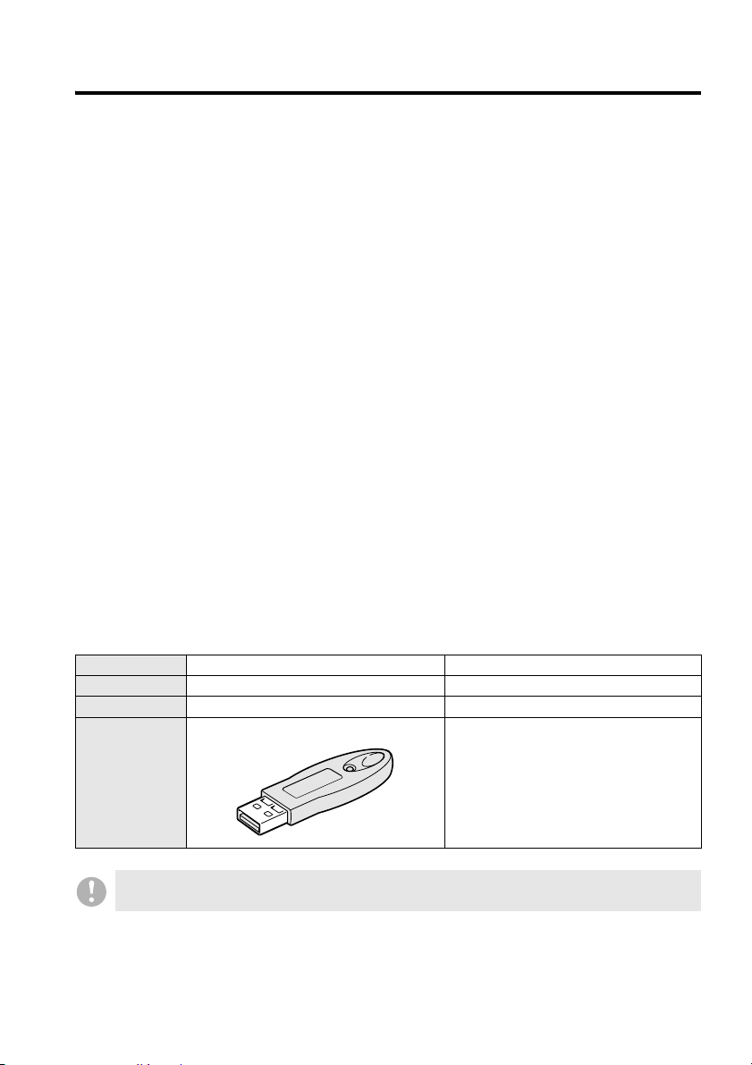
Bundles Hardware key (USB type) None
The VA-SW8000 (Standard Edition) cannot be started without the supplied hardware key
connected to a USB port of the computer.
English 2
Page 4
Network Configuration
b Network Device Configuration
With the DVR Utility Software, you create a monitoring system that consists of DVRs, monitoring
cameras, and one or more computers that act as remote controllers, all of which are connected via
a dedicated independent network.
● Supported DVR Models
The DVR Utility Software supports the SANYO DVR models listed below.
All DVRs need not be the same model; a single network can contain two or more different models
as needed.
• Single-channel models: DSR-M800, DSR-M800P, DSR-M800PA, DSR-M810, DSR-M810P
• Four-channel models: DSR-M804, DSR-M804P, DSR-M814, DSR-M814P
• For SANYO DVR models not listed above, visit the SANYO Web site
(http://www.sanyosecurity.com) and check the latest information.
• For the sake of simplicity, this guide assumes the use of the DSR-M804 or DSR-M814.
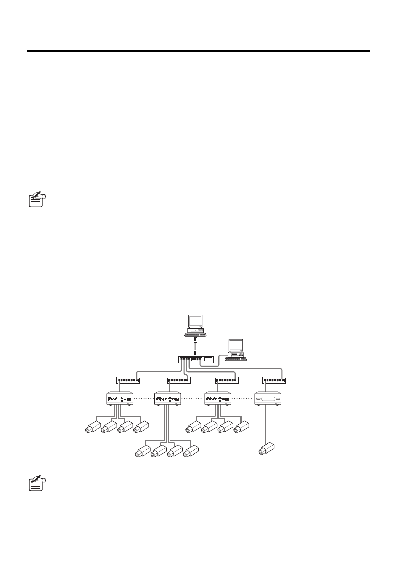
● Network Scalability
The dedicated network can accommodate the following:
• Up to 1,000 DVRs in the standard configuration
(or up to a maximum of 4000 DVRs when an appropriate subnet mask setting is used)
• Cameras: Up to four times the maximum number of DVRs
• Up to eight computers (one master plus seven slaves)
Master computer
Slave computer
Switching hub
Switching hub
DVR1 DVR2 DVR3 DVR4
About Master and Slave Computers
During initial setup, you specify a single computer that is authorized to register or delete
networked DVRs, and this is called the Master computer. In addition to the Master computer,
you can configure up to seven additional computers that are not authorized to register or
delete networked DVRs, and these computers are called Slave computers.
After you have started the DVR Utility Software on a computer and logged into the system,
you can determine whether to configure the computer as either “Master” or “Slave” using the
[Options] window accessible from the Initial Set menu. For more information, see P73.
3 English
Page 5
Network Configuration
b Hardware and Software Requirements
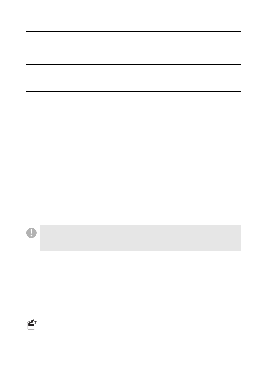
The DVR Utility Software requires following hardware and software:
Computer IBM PC/AT and compatibles
Operating system Windows XP Professional SP2
CPU Pentium 4, 3GHz or higher
Memory 512MB or more
Interfaces 100Base TX and USB (1.1)
Display
XGA (1024 x 768 pixels), 16 million colors or higher*
AGP graphics card with hardware overlay support
Or PCI Express graphics card*
2
<Recommended graphics chip>
ATI : RADEON9000 series or higher
nVidia : GeForce4 series or higher
: Quadro4 series or higher
Matrox : MillenniumP series or higher
Sound Sound card with 48 kHz stereo playback support (PCI connection
recommended)*
3
*1: When using the software at a resolution of 1024 x 768 pixels, open Windows Taskbar
Properties dialog box and select the “Auto hide” check box.
*2: Requires the latest DirectX 9.0c compatible driver.
*3: A sound card is required to listen to the sound part in live or played back video.
Windows is a trademark or registered trademark of Microsoft Corporation in the United States and/or other
countries.
Pentium
is a trademark or registered trademark of Intel Corporation and its subsidiaries in the United States and/or
other countries.
IBM and PC/AT are trademarks of IBM International Business Machines Corporation.
1
• Meeting the above requirements does not guarantee consistent, stable video feed; video may
not be correctly displayed due to a disturbance in sync signals.
• If the computer is underpowered or overloaded, the system may not function as expected,
typically failing to display video frames smoothly at the correct rate.
b Notes on Version Compatibility
All networked computers (the Master and Slave computers) must have the same edition of DVR
Utility Software installed (i.e., either VA-SW8000 or VA-SW8000LITE).
The DVR Utility Software in this new version (either the Standard or Light edition) is not compatible
with any of the previous versions (VA-SW800/804/814/80LITE/81LITE), and therefore any Slave
computers currently running an old version must be upgraded to the new version. Note that the
hardware key (or serial number) from a previous version can still be used after the software has
been upgraded to the new version.
On the upgraded computer, you can use any DVR registration lists created in a previous
version by following a specific procedure (see P85).
English 4
Page 6
Network Connection Requirements
Before using the DVR Utility Software, configure the DVRs and computers for network connectivity
as instructed in the following sections.
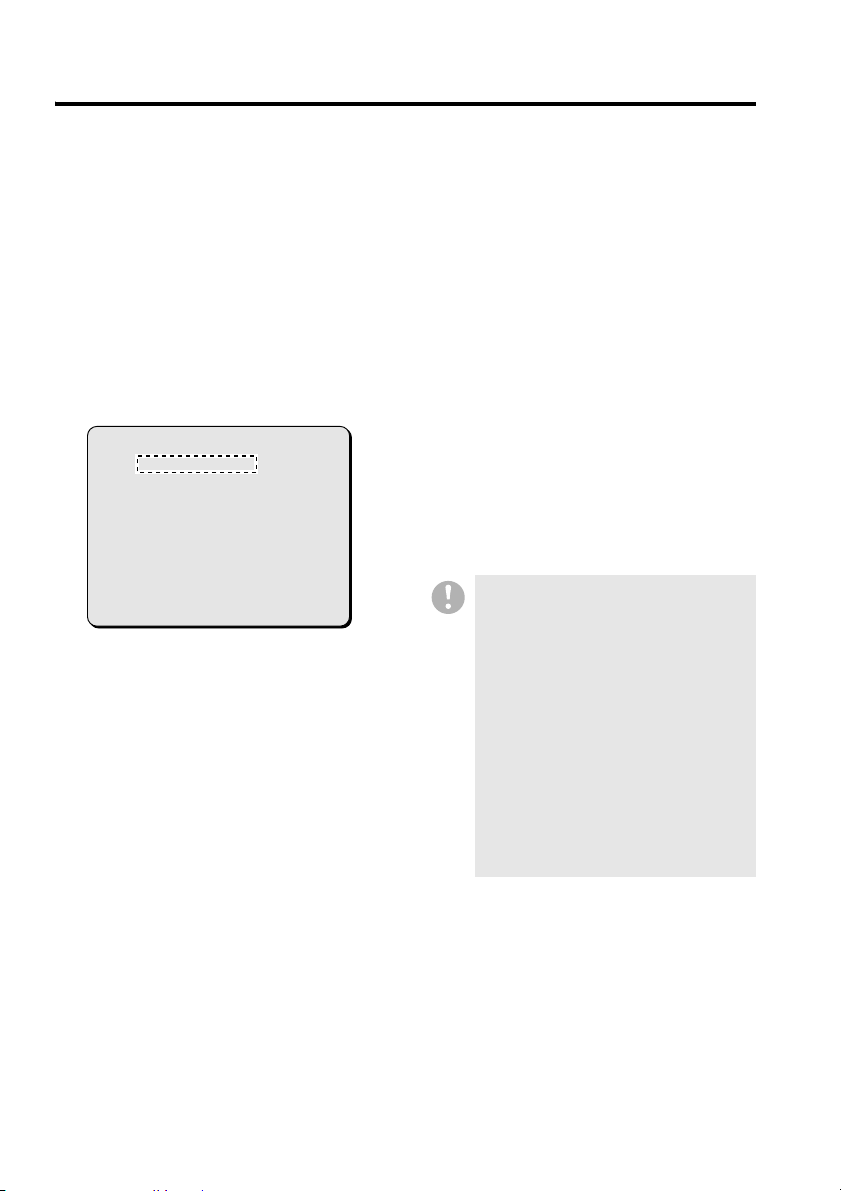
● Configuring the DVRs
Configure NETWORK SET by following the
instructions for IP address configuration given
in the DVR’s documentation.
• Auto configuration
Set [ADDRESS SET] to “AUTO”.
• Manual configuration
Set [ADDRESS SET] to “MANUAL”, and
configure the IP address and subnet mask.
< NETWORK SET - ADVANCED >
ADDRESS SET : AUTO
DVR NAME : DVR1
IP ADDRESS : 192.168. 0. 1
SUB NET MASK : 255.255.255. 0
● Configuring the Computers
Configure the TCP/IP settings by following the
relevant instructions given in the operating
system documentation. For more information,
see P6.
Examples of configured IP address
ranges:
(These examples assume that IP address
settings are configured in Auto configuration
mode with the subnet mask set to the default
of “255.255.252.0”.)
DVRs:
192.168.0.1-250
192.168.1.1-250
192.168.2.1-250
192.168.3.1-250
• All the DVRs and computers must
have their IP addresses configured in
the same segment.
• Check with the network administrator
to make sure that the IP addresses
that you want to use do not conflict
with IP addresses that are already in
use by the network.
• If you connect a LAN cable or change
the TCP/IP settings while the DVR
Utility Software is running, a
communication error may result. Be
sure to quit the DVR Utility Software
before making any change to the
physical cable connection or the
TCP/IP settings.
Computers:
192.168.0.251-254
192.168.1.251-254
192.168.2.251-254
192.168.3.251-254
5 English
Page 7
Network Connection Requirements
Configuring the TCP/IP Settings
To configure the TCP/IP settings on each computer, follow these steps:
The DVR Utility Software supports Windows XP only.
On the [Control Panel], click [Network
1
and Internet Connections].
The [Network and Internet Connections]
window appears.
Click [Network Connections].
2
The [Network Connections] window
appears. Make sure that the appropriate
LAN card (Ethernet adapter) is shown
under [LAN or High-Speed Internet].
Right-click on the LAN card (Ethernet
3
adapter), and then select [Properties
(R)] from the pop-up menu.
The [Local Area Connection Properties]
window opens, and the [General] tab is
selected by default.
Make sure that [Internet Protocol
4
(TCP/IP)] is checked (selected) under
[This connection uses the following
items: (O)].
If [Internet Protocol (TCP/IP)] is not
checked, select the check box.
Click [Properties (R)].
5
The [Internet Protocol (TCP/IP)
Properties] window opens, and the
[General] tab is selected by default.
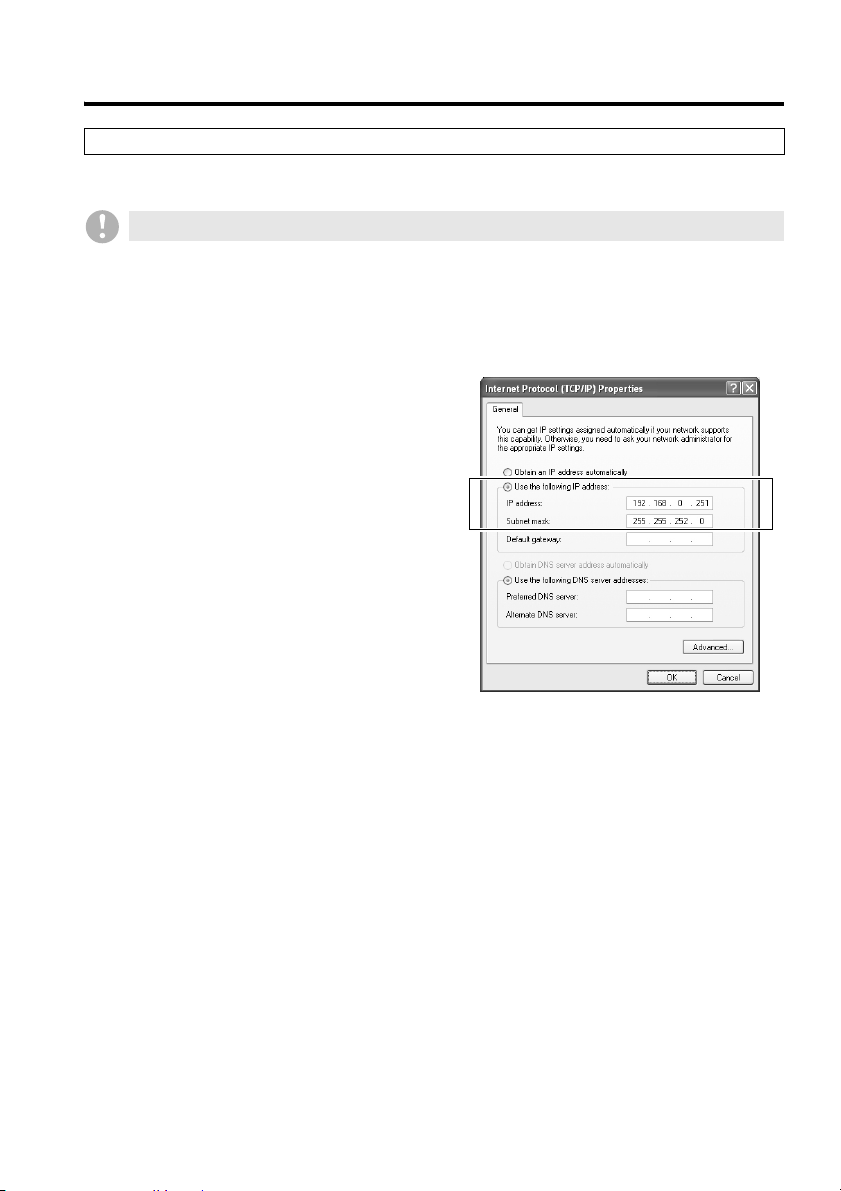
Select the [Use the following IP
6
address:] check box, and type in the
IP address and the subnet mask.
For the standard configuration, enter a
subnet mask of “255.255.252.0”.
Check the settings, and then click
7
[OK].
This returns you to the [Local Area
Connection Properties] window.
Click [OK].
8
Now the TCP/IP settings have been
configured.
English 6
Page 8
Installing the Software
The DVR Utility Software must be installed on each computer you want to connect to the dedicated
network. The Setup program that runs from the Installation CD guides you through the process of
installation.
When you install the DVR Utility Software, the “hardware key driver” and “MP2 Viewer”
(playback-dedicated application software) are installed as well.
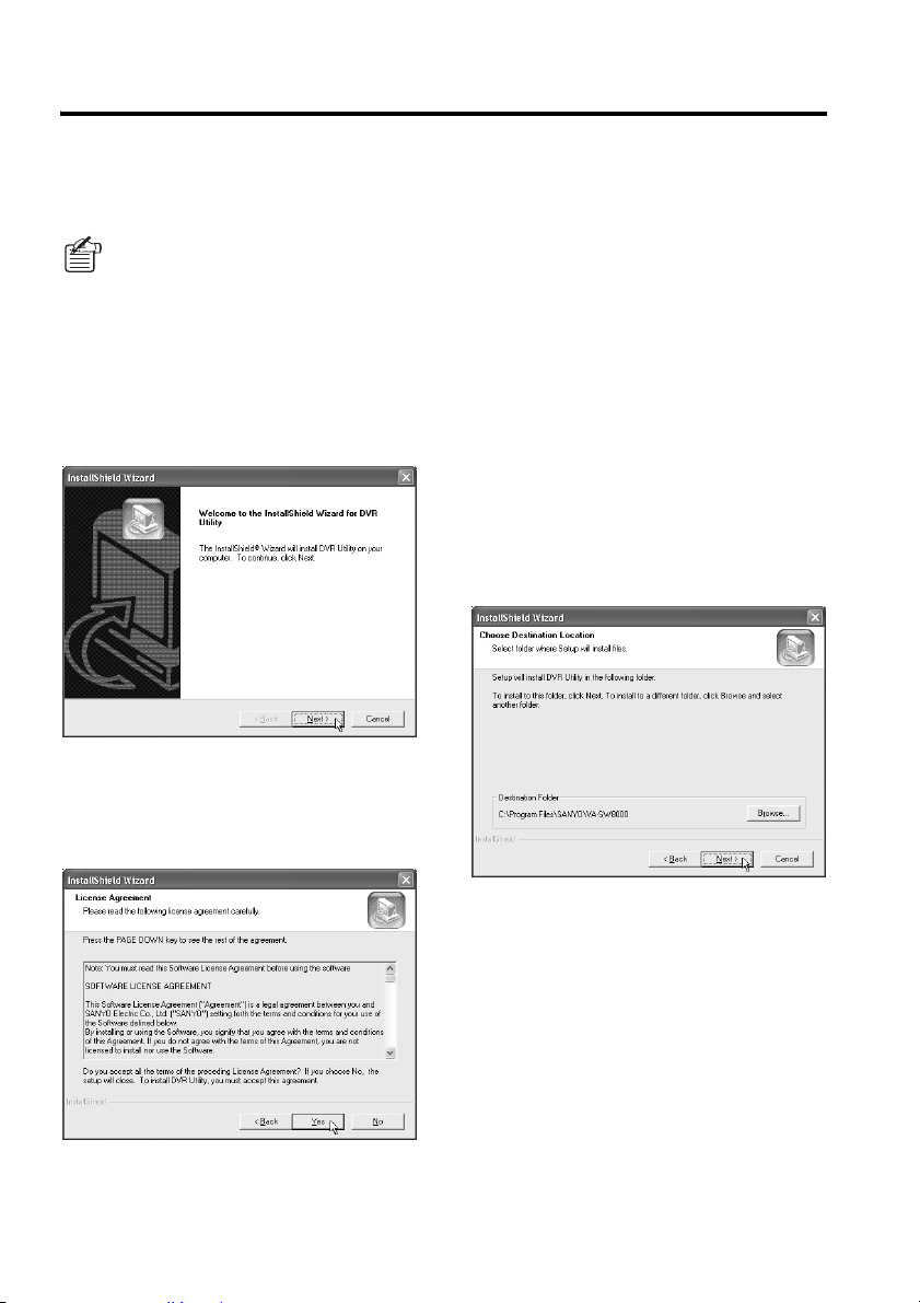
Insert the Installation CD into the
1
CD-ROM drive of the computer.
The “Welcome” screen appears.
Click [Next] on the “Welcome” screen.
2
The [License Agreement] screen
appears.
Click [Yes] in the [License Agreement]
3
window.
Read and accept the User License
Agreement displayed on the screen.
The [Choose Destination Location]
4
screen appears. Accept the default
location or specify another location,
and click [Next].
Accept the default installation folder
unless your situation requires another
location (for example, due to disk
capacity limitation), and click [Next].
If you want to override the default
installation folder for some reason, click
the [Browse..] button and select a
different folder where you want to install
the software.
7 English
Page 9
Installing the Software
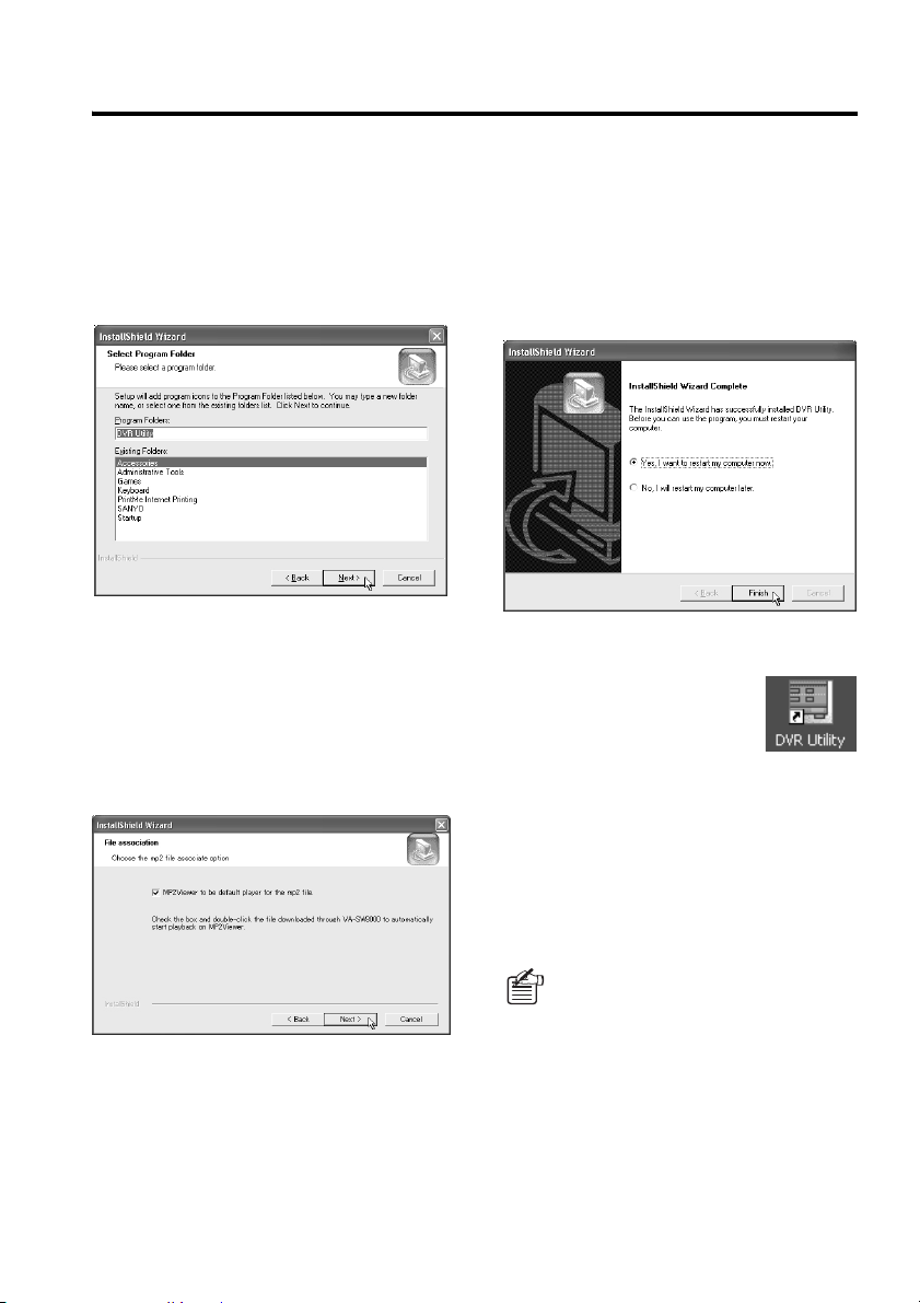
The [Select Program Folder] screen
5
appears. Check the program folder,
and click [Next].
Normally you can accept the default
folder without changing it. If you want to
change the program folder, type the
folder name into the box, or select an
existing folder from the list underneath.
Configure file association on the [File
6
association] screen and click [Next].
When you select the check box,
double-clicking the MP2 file (the file
extension “mp2” file saved in MPEG2
format) that was downloaded by this
software automatically starts playback on
the “MP2 Viewer” (see P58, 125).
Reboot the computer.
8
When the “Installation completed”
message is displayed, specify whether to
reboot your computer right now or later
by selecting the appropriate option, and
then click [Finish]. If you choose the first
option (default), your computer will be
automatically rebooted after you exit
from the Setup program.
Make sure that shortcut icon has been
9
created.
After rebooting your
computer, make sure that
the “DVR Utility” shortcut
icon is displayed on the
desktop. You can double-click the icon to
start the DVR Utility Software.
Start the Installation Process.
7
When you click [Next] on the previous
screen, the Setup program starts the
installation process, and the [Setup
Status] screen indicates the setup status
with progress bars.
☞How to uninstall the software
To uninstall (remove) the DVR Utility Software,
open the [Add or Remove Programs] window
from Windows control panel. Select “DVR
Utility”, and click the [Remove] button.
When you upgrade to the new version
of the DVR Utility Software, accept the
option to remove the old version in the
confirmation dialog displayed during
the installation of the new version.
Then the old version will be
automatically removed.
English 8
Page 10

Setting Up the System
Once you have completed the installation process, you should set up your monitoring system to
make it up and running as outlined in this section.
This section simply describes basic procedures; for more information, see the descriptions given on
the referenced pages.
Starting Up the Master Computer and Configuring Initial Settings
As outlined below, start up the Master computer, and configure settings that are required to make
the system up and running.
Start the software (see P13).
1
Double-click the shortcut icon on the
desktop to access the Login window.
Log into the system (see P14).
2
Enter your user name and password.
When you log in for the first time, enter
the default values for user level ID4.
Default values:
• User Name: ID4
• Password: 4444
Register DVRs (see P81).
3
Once you have logged in, the [Register
DVR] window (accessible from the Initial
Set menu) is automatically displayed. On
this window, register DVRs you want to
connect to the network.
Configure other initial settings (see
4
P73).
Once you have registered the DVRs,
your computer starts receiving live video
fed from the registered DVRs and you
can watch the video on the computer
screen.
In addition, you can access the settings
specific to the registered DVRs
(cameras) through the computer screen.
Use the following menu items contained
in the Initial Set menu to configure other
settings as needed.
• Options:
You can configure settings pertaining
to the system environment and
operating conditions.
• Tree Edit:
You can add camera titles and groups
to the tree list to make it
well-organized.
• User ID:
Configure user names and passwords
that are required when logging into
the system.
Configure advanced settings as
5
needed.
Now the Master computer is ready for
basic operations.
After this, configure advanced settings
using various configuration menu items,
and customize your system based on
actual monitoring needs.
(The following sections describe how to
connect Slave computers and how to
disable the firewall protection at the initial
start-up.)
9 English
Page 11
Setting Up the System
Setting Up Slave Computers
If your system uses additional computers
(“Slave” computers) connected to the network
in addition to the Master computer, be sure to
configure the following initial settings before
letting end users use the system. This
procedure must be performed on each of the
computers you want to use as Slave
computers.
Start the DVR Utility Software, and log
1
in using user level ID4 (see P14).
Log in as an administrative user so that
you have access to the Initial Set menu.
Open the [Options] window from the
2
Initial Set menu, and configure initial
settings as needed (see P73).
Set [PC TYPE] to “SLAVE”, and enter
the IP address of the Master computer.
Configure the display language and other
options as needed.
Log out of the system (see P14).
3
Now the Slave computer has its initial
settings configured so that the end users
can use it.
You can connect up to seven Slave
computers to the network.
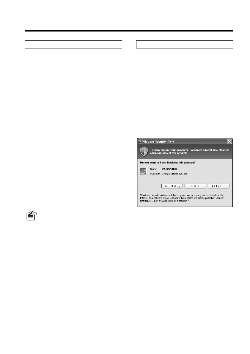
Disabling the Firewall Protection
When Windows XP Firewall or some other
firewall program is active on your computer,
the computer is blocked from communicating
with the DVRs and thus the system fails to
operate correctly. This means that you must
disable the firewall protection before you begin
using the DVR Utility Software.
Note that, if you are using Windows XP SP2,
its firewall protection is enabled by default.
When you run the DVR Utility Software for the
first time, Windows XP SP2 displays a window
where you can choose firewall options; select
[Unblock] so that your computer is not blocked
from receiving traffic from the DVRs.
English 10
Page 12

Menus and User Access Levels
The system uses four access levels to authorize users. Users are authenticated with passwords at
login time. Menu items accessible to a user are determined by the user level assigned to that user.
A user with access level ID4 can access the [User ID] window from the Initial Set menu and change
the passwords and IDs for all users.
User name (default) ID1 ID2 ID3 ID4
Password (default) 1111 2222 3333 4444
Monitor live video
Playback
Search
Save
Record
DVR
management
Menu items and functions
Tool*
Initial Set
User level
Date/Time Search
Alarm Search
Save/print snapshot images
Download
Play back downloaded files
Manual recording
Timer recording
DVR configuration, firmware
update, etc.
Timer download (scheduled
download)
Manual recording,
Broadca
st
Tamper detection
System Preferences,
Register User ID
Register DVR, Tree Edit
timer recording
Menu upload,
clock setting,
system update
ID1
(Monitoring
user)
ID2
(Playback
user)
ID3
(Recording
user)
ID4
(
Administrative
user)
FFFF
FFF
FFF
FFF
F)(F) F
(
F)(F) F
(
FFF
FF
FF
F
F)(F) F
(
FF
F
FFF
F
E
E : This menu item is only accessible from the Master computer.
* : The Tool menu is not available with VA-SW8000LITE.
( ): Access to these menu items can be configured by a user with access level ID4 through the
Initial Set - [Options] window.
Throughout this guide, user access levels are indicated in page titles or somewhere else when
referring to menu items or functions that require specific user access levels. For example,
“(User access level: ID3/4)” means that the menu item or function is only available to users with
access level ID 3 or 4.
11 English
Page 13
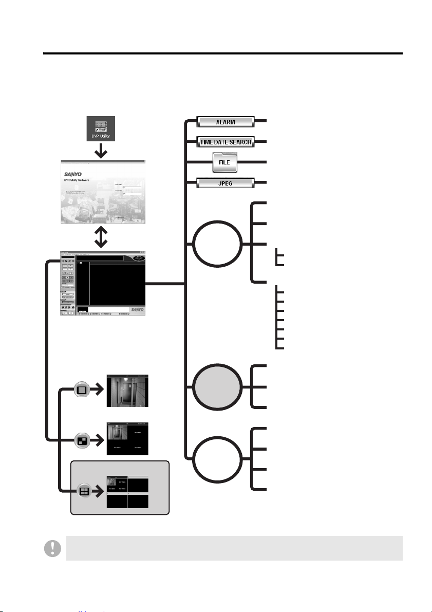
Window Navigation
When you have started the software and logged into the system, you are first presented with the
main window. The main window is where you watch video during routine monitoring work and, in
addition, it allows you to navigate to other windows where you can control or configure various
aspects of the system.
Alarm Search window (P45)
Time Date Search window (P44)
Play List (P56)
Dialog boxes for saving/printing a still
image (P59)
Clock Set window (P95)
Login window
(P14)
Main window
(P16)
Viewing pane layouts (P25)
1 Single-view layout
2 Four-view layout
3 Multi-view (4x4) layout
DVR
Management
menu
Too l
menu
Initial Set
menu
System Update window (P96)
DVR info window (P97)
INFORMATION 1 tab
INFORMATION 2 tab
DVR Set window (P100)
LANGUAGE/D.S. TIME tab
REC MODE SET tab
TIMER REC SET tab
HOLIDAY SET tab
DISPLAY/BUZZER SET tab
MONITOR SET tab
TITLE/MOTION SET tab
Timer Download window (P61)
Broadcast window (P70)
Tamper Detection window (P72)
Options window (P73)
Tree Edit window (P76)
Register DVR window (P81)
User ID window (P89)
• Some windows are only available to users with specific user access levels.
• If you are using VA-SW8000LITE, you cannot access the multi-view layout or Tool menu.
English 12
Page 14
Starting and Ending a Monitoring
Session
To start a monitoring session with the system, you have to start the DVR Utility Software and log into
the system. Follow these steps:
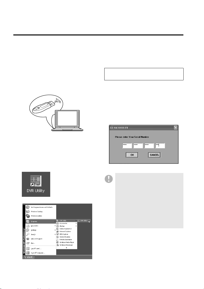
b Starting the Software
Plug in the hardware key.
1
The hardware key (supplied in the
Standard Edition package) must be
plugged into a USB port of your
computer.
Double-click the DVR Utility shortcut
2
icon on the desktop.
Alternatively, click Windows Start button,
point to [Programs], point to the [DVR
Utility] group, and then click [DVR Utility].
The Login window appears.
Starting the software without
the hardware key
If you are using the Light Edition
(VA-SW8000LITE), which does not include
the hardware key, simply start the software.
When you have started VA-SW8000LITE, you
are prompted to type in the serial number
indicated on the CD-ROM disc label. Type in
the correct number, and the Login window
appears.
13 English
• The dialog box that prompts you to
type in the serial number appears
once and only once when you start
the software for the first time.
• If the serial number dialog box
appears when you are starting the
Standard Edition (VA-SW8000), it
means that the hardware key is not
correctly plugged in. If this is the
case, make sure that the hardware
key is in place, and try again to start
the software.
Page 15
Starting and Ending a Monitoring Session
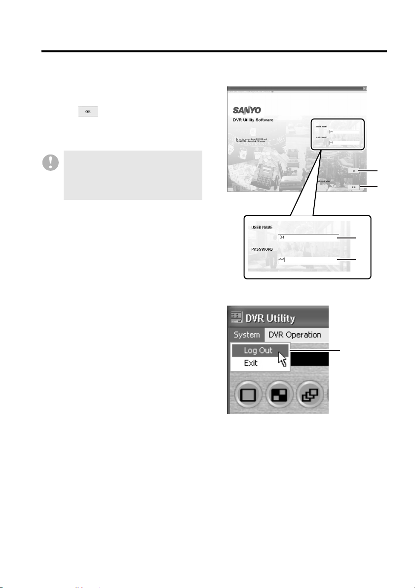
b Logging Into the System
When the software has successfully started
up, you are presented with the Login window.
Enter your user name (
then click (
If your entered user name and password are
valid, the main window appears.
If you fail to enter valid user name and
password three times in succession, an
authentication error window appears.
In this case, close the window and try
again to start the software.
b Logging Out of the System
To log out, open the [System] pull-down menu
from the menu bar, and then click [Log Out]
5). The currently displayed window is
(
closed, and you are returned to the Login
window.
1) and password (2),
3) or hit the [Enter] key.
3
4
1
2
5
English 14
Page 16
Starting and Ending a Monitoring Session
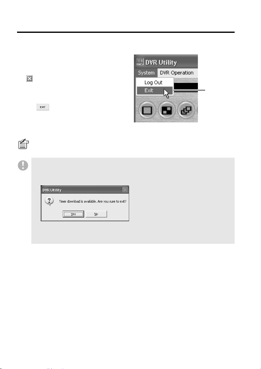
b Exiting from the Software
• To exit when working with the main
window:
Open the [System] pull-down menu and
select [Exit] (
( ) in the upper right corner of the
window.
• To exit when the Login window is
displayed:
Click (
screen.
To configure additional user names and passwords in addition to the defaults, use the [User
ID] screen, which is accessible from the Initial Set menu. For more information, see P89.
6); or click the Close button
4) at the bottom of the
• When a timer download is scheduled but not yet started or while a timer download is ongoing,
a confirmation dialog is displayed if you try to log out of the system (or exit from the software).
If you choose to log out or exit, the timer download is canceled. For more information, see
P67.
6
• Except for situations where the software does not respond to keyboard or mouse actions, the
above procedure must be followed whenever you exit from the DVR Utility Software;
otherwise, an unexpected problem may result.
15 English
Page 17
Main Window Elements and Their Functions
When you have logged into the system, you are first presented with the main window. The main
window is where you monitor live video and perform “basic monitoring-user level operations” such
as recording and playback, and allows you to navigate to other windows where you can control or
configure various aspects of the system.
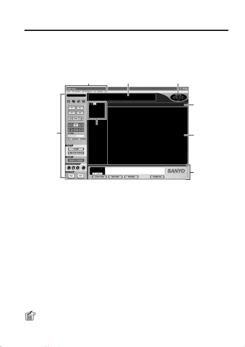
b Window Elements
1 3 4
5
2
Menu bar (see P17)
1
Contains pull-down menus that provide
access to various commands available in the
DVR Utility Software.
Control panel (see P19)
2
Contains buttons that provide access to the
most common commands.
Message window
3
Displays information on operation status,
results, and alarm as well as error messages.
Current date and time
4
Indicates the current date and time from the
computer's internal clock in the format
configured on Windows.
Title bar (see P29)
5
Displays basic information on the currently
displayed video, including the camera (DVR)
titles and operating modes.
66
8
7
Tree list (see P23)
6
Displays the titles of registered cameras and
groups as a tree list. When designating
cameras or groups for various operations,
click titles from this list.
Time scale panel (see P21)
7
Allows you to specify the time range of video
data you want to download. (Normally, the
time scale indicates the date and time of the
currently displayed video.)
Viewing pane (see P25)
8
The viewing pane normally displays live or
recorded video. When you perform a
non-monitoring operation or configuration
task, the appropriate information is displayed
in this area.
Due to limited space, lettering in the message window and title bar may be partially
abbreviated. In such cases, move the cursor to the abbreviated area to complementarily
display the invisible part.
English 16
Page 18

Main Window Elements and Their Functions
b Menu Bar
The menu bar located along the top of the window contains six pull-down menus. When you click
one of the menus, you are presented with a list of commands you can use to perform various tasks
such as switching the viewing pane layouts or configuring system settings.
Select... To...
Required user
access level
1System
• Log Out Log out of the system and return to the Login window. (ID1/2/3/4)
• Exit Exit from the DVR Utility Software and close all its
windows.
(ID1/2/3/4)
2DVR Operation
• DVR List(*) Show or hide the tree list. (ID1/2/3/4)
• Connect DVR Monitor a video camera. (ID1/2/3/4)
•
Disconnect DVR(*)
• Open File(*) Open a file (display the [Play List] window). (ID2/3/4)
• Display(*) Specify the viewing pane layout and channel set.
• Zoom In(*) Zoom in on the currently displayed image. (ID1/2/3/4)
• Zoom Out(*) Zoom out on the currently displayed image until it
• Live(*) Stop playback and switch to live mode. (ID2/3/4)
• Play(*) Start playback. (ID2/3/4)
• Still(*) Pause the playback to display the current video frame
• Frame(*) Frame-step the playback. (ID2/3/4)
• Slow(*) Slow-play the video at one of three variable speed
• Forward(*) Fast-forward playback at one of five variable speed
• Reverse(*) Fast-reverse playback at one of five variable speed
• Alarm Search(*) Navigate to the [Alarm Search] window. (ID2/3/4)
• Download(*) Navigate to the [Download] window. (ID2/3/4)
• Save as JPEG(*) Navigate to the window for saving the snapshot (still
• Print(*) Navigate to the window for printing the snapshot (still
• REC Start(*) Start manual recording. (ID3/4)
• REC Stop(*) Stop manual recording. (ID3/4)
• Timer(*) Turn on or off the timer recording mode. (ID3/4)
• Audio(*) Configure the audio output channels.
• Audio Mute(*) Turn on or off the sound output. (ID1/2/3/4)
Stop displaying the video streamed from a DVR (camera).
(Multi Monitor/Single Monitor/Ch1/Ch2/Ch3/Ch4/
Quad Monitor/Sequence/Full Screen)
reverts to the original size.
as a still image.
levels. (x1/2, x1/4, and x1/8)
levels.
(x2, x7.5, x15, x30, and x180)
levels.
(–x2, –x7.5, –x15, –x30, and –x180)
image) as a JPEG file.
image).
(Ch1+Ch2, Ch3+Ch4)
(ID1/2/3/4)
(ID1/2/3/4)
(ID1/2/3/4)
(ID2/3/4)
(ID2/3/4)
(ID2/3/4)
(ID2/3/4)
(ID2/3/4)
(ID2/3/4)
(ID1/2/3/4)
17 English
Page 19

Main Window Elements and Their Functions
Select... To...
Required user
access level
3DVR Management
• Clock Set Navigate to the [Clock Set] window. (ID4)
• System Update Navigate to the [System Update] window. (ID4)
• DVR Info Navigate to the [DVR Info] window. (ID4)
• DVR Set Navigate to the [DVR Set] window. (ID4)
4Tool
• Timer Download Navigate to the [Timer Download] window. (ID2/3/4)
• Broadcast Navigate to the [Broadcast] window. (ID3/4)
• Tamper Detection Navigate to the [Tamper Detection] window. (ID2/3/4)
5Initial Set
• Options Navigate to the [Options] window. (ID4)
• Tree Edit Navigate to the [Tree Edit] window. (ID4)
• Register DVR Navigate to the [Register DVR] window. (ID4)
• User ID Navigate to the [User ID] window. (ID4)
6Ver.
• Web Page Go to the relevant Web page. (ID1/2/3/4)
• About... Displays the version of the software currently in
use.
• Commands marked with an asterisk (*) are accessible from the Control Panel as well (see
P19).
• Commands available to a logged-in user are determined by the access level assigned to that
user.
The “Required user access level” column indicates the user access level(s) required to use
the function.
• ID2 and ID3 access to Download, Timer Download, Save as JPEG, and Print menu items can
be controlled using the [Options] screen under the Initial Set menu. For more information, see
P73.
(ID1/2/3/4)
English 18
Page 20
Main Window Elements and Their Functions
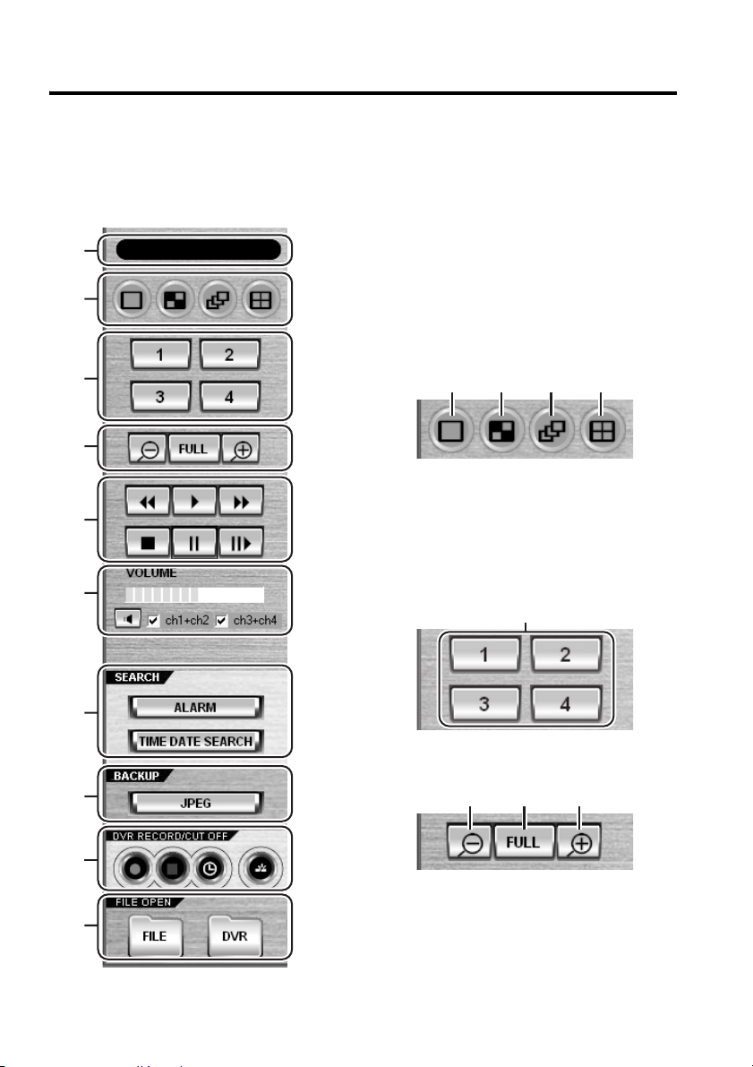
b Control Panel
The control panel contains buttons that provide one-click access to the most common functions
such as specifying the channel configuration, switching the viewing pane layouts, playing back or
recording video as well as to various control/configuration windows.
1 Operating mode indicator for timer
1
2
3
download
• Program: There is a scheduled timer
download that has not been started yet.
• Downloading: A timer download is
ongoing.
2 Layout selector buttons (ID1/2/3/4)
1 2 3 4
4
1 Single-view layout
2 Four-view layout
5
3 Sequence (auto switch) mode
4 Multi-view (4x4) layout
6
7
8
9
À
19 English
3 Channel selector buttons (ID1/2/3/4)
Display channel selection
4 Zoom/scale buttons (ID1/2/3/4)
2 3 1
1 Zoom in on the currently displayed
image
2 Zoom out on the currently displayed
image until it reverts to the original size.
3 Full screen mode
Page 21
Main Window Elements and Their Functions
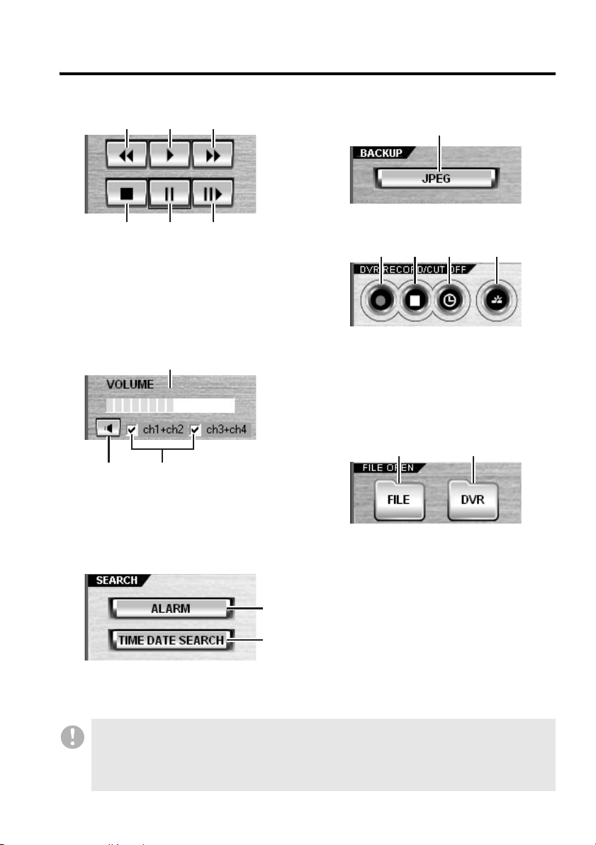
5 Playback control buttons (ID2/3/4)
1 2 3
4 5 6
1 Fast-reverse
playback
2 Play
3 Fast-forward
playback
4 Stop
(switch to live mode)
5 Pause
6 Slow-play
6 Sound playback panel (ID1/2/3/4)
1
23
1 Sound volume
2 Turn on/off sound output
3 Configuration of the sound output
channel
7 Search buttons
8 Save button (ID2/3/4)
Opens dialog boxes for
saving/printing a still image
9 Record/cut-off buttons
1 2 3 4
1 Start manual recording (ID3/4)
2 Stop manual recording (ID3/4)
3 Turn on or off the timer recording mode.
(ID3/4)
4 Disconnect the DVR. (ID1/2/3/4)
À List display buttons
1 2
1 Open a playlist (play back downloaded
files) (ID2/3/4)
2 Show/hide the tree list (ID1/2/3/4)
1
2
1 Navigate to the [Alarm Search] window
2
Navigate to the [Time Date Search] window
• The functions assigned to the control panel buttons are all available from the menu bar as well;
however, for simplicity, the procedures contained in this guide assume the use of the control
panel buttons.
• Commands available to a logged-in user are determined by the access level assigned to that
user. The text in parentheses indicates the user access level(s) required to use the function.
English 20
Page 22

Main Window Elements and Their Functions
b Time Scale Panel
The time scale panel, which contains a movable time scale and control buttons, allows you to
specify the time range of the video data you want to download. Also, the time scale panel is useful
when you explore video frame images in playback mode: you can easily move the playback point by
dragging the time scale.
When a user with user access level ID1 is logged on, the timer scale panel functionality is
restricted to the display of date and time.
12
3
4
1 Time scale
The time scale indicates the date and time
of the currently displayed video.
• In live mode: Current date and time
• In playback mode: Date and time of
recording
2 Time display
Indicates the digits of the date and time
(time stamp) of the currently displayed
video.
3 Scale unit
Indicates the currently selected time scale
unit.
21 English
4 Control buttons
• START POINT:
Sets the download start point.
• END POINT:
Sets the download end point.
• PREVIEW:
Plays back to preview the video data
within the download range.
• DOWNLOAD:
Navigate to the [Download] window.
Page 23
Main Window Elements and Their Functions
How the Time Scale Works How to Use the Time Scale
The time scale is a tool that allows you to view
or specify time and date information. The
scale part is movable; it automatically slides
as the video advances. The date and time of
live or recorded video is always displayed in
the middle of the scale, where a green vertical
center line resides.
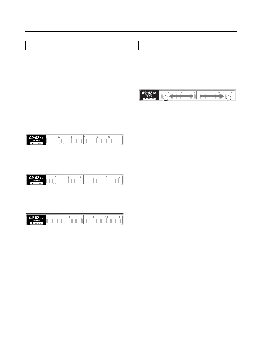
• The scale unit (DAY/HOUR/MINUTE) can
be selected from the pull-down menu.
The scale display range varies depending
on the selected unit.
DAY:
Center line ±15 days (30 graduations in all)
HOUR:
Center line ±12 hours (24 graduations in
all)
MINUTE:
Center line ±30 minutes (60 graduations in
all)
• The time and date that corresponds to the
vertical center line on the scale is shown on
the digital time display on the left-hand side
of the scale.
• In live mode, the scale indicates the current
date and time.
• In playback mode, the scale indicates the
date and time (time stamp) when the
currently displayed video was recorded. The
time and date information reflects
fast-forward playback or other operations.
• The scale moves in increments of one
graduation.
For example, when the scale unit is set to
“MINUTE”, the scale slides every one minute.
• When the scale spans two days or two
months, the day or month is highlighted in
red.
In playback mode, you can move the playback
point along the scale by dragging the scale to
the left or right.
• You can advance the time by sliding the
scale to the left, or reverse the time by
sliding the scale to the right.
Advances the time. Reverses the time.
• This feature is very useful when you
explore video frame images in playback
mode: you can move the playback point as
many times as you like by dragging the
scale. (The playback point can be moved
even when the video is paused.)
• Instead of dragging the scale, you can
double-click a graduation on the scale to
move the playback point to that position.
• The time scale can be used in live mode as
well. When you specify a point in time on the
scale by dragging the scale or double-clicking
a graduation, the DVR Utility Software
switches to playback mode on condition that
there is recorded video data that corresponds
to the specified point in time.
• When you download recorded video data,
you can specify the start and end points of
the time range of video data you want to
download, by dragging the scale just as
you do when you specify the playback
point. For more information, see P49.
English 22
Page 24
Main Window Elements and Their Functions
C
b
b Tree L i s t
When you monitor or record live video or perform a related configuration task, you can specify the
camera or group you want to connect and operate by selecting from the tree list.
•
The tree uses camera titles, group titles, and hierarchical tree nodes as defined on the [Tree Edit]
window accessible from the Initial Set menu. For more information, see P76.
•
The tree list is hierarchical: lower level tree nodes can be opened and closed by clicking the /
buttons on the left.
•
The [DVR] button the control panel can be used to show or hide the tree list.
When there is one or more video streams displayed on the viewing pane, the camera with a blue
title bar is the target of an operation.
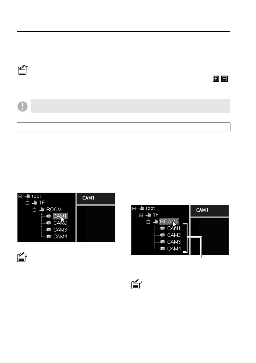
Specifying the Target of the Command (by a Single-Click)
☞To select a camera as the target:
To select a camera, click the camera title node
on the tree list. The clicked title is highlighted
to indicate that it is currently selected.
When you run a command by clicking a
control panel button or menu item after
selecting a camera, that command is applied
to the selected camera.
When connected to 4-channel DVRs,
four cameras can be displayed per
DVR.
If using commands such as record and
playback that are applicable to
individual DVRs, executing the
command to just one of the four
cameras will cause the other three to
automatically follow suit.
☞To select a group as the target:
Clicking a group name will cause all the
cameras belonging to that group to be
selected.
When designating a group for execution of a
command, right-click the group name to
display the context menu, and select the
command from the menu. Four tasks, i.e.
"Expand/Collapse", "Live", "Play" and "Tree
Edit" are possible (see P24).
licking a group name will cause all the cameras
elonging to that group to be selected.
By designating the group and selecting
either “Live” or “Play” from the context
menu, videos will be automatically
displayed in the multi-view layout.
If the number of cameras in a group
exceeds the number of panes in the
multi-view layout, videos will only be
displayed from the top four cameras on
the list.
23 English
Page 25
Main Window Elements and Their Functions
Directly Running a Command (by a Double-Click)
Some of the windows accessible from the menu bar allow you to directly run a command by
double-clicking a camera title.
• In live mode, when you double-click a camera
title, the software switches to the DVR to
which the camera is connected, and displays
the live video from the camera.
If the cameras are connected to an
identical DVR, use the channel
selector buttons to switch the live
video as desired.
• In the [DVR Set] window and [DVR Info]
window, both accessible from the DVR
Management menu, double-clicking a camera
title causes the software to retrieve the
information on the DVR to which the camera is
connected (thus providing a function similar to
[Import]).
Similarly, when you double-click a camera title
in the [Alarm Search] window, the software
retrieves the alarm list information.
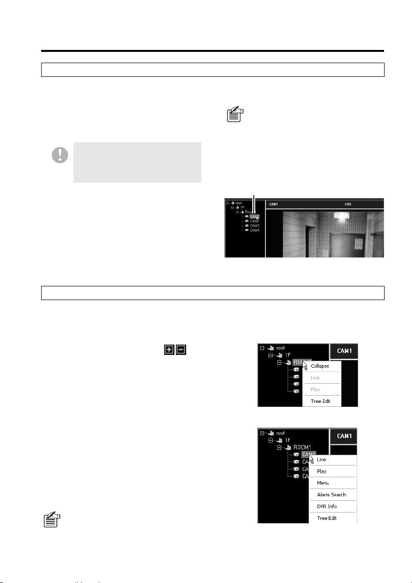
Working with the Context Menu
The context menu appears when you right-click a camera title or group name. From the context
menu, you can directly run the following commands without having to click a control panel button or
open a menu from the menu bar:
• Expand/Collapse:
Provides the same function as the
buttons.
• Live:
Displays live video in the single-view layout
when a camera is selected; or
Displays live video in the multi-view layout
when a group is selected.
• Play:
Plays back recorded video in the single-view layout
when a camera is selected; or
Plays back recorded video in the multi-view layout
when a group is selected.
• Menu: Opens the [DVR Set] window
• Alarm Search: Opens the [Alarm Search]
window
• DVR Info: Opens the [DVR Info] window
• Tree Edit: Opens the [Tree Edit] window
When you double-click a camera title
when working in one of the mentioned
windows, the software displays a
confirmation dialog before it actually
retrieves the DVR or alarm information.
Respond to the confirmation dialog by
clicking the appropriate button.
Double-click
When a group name is right-clicked
When “Menu”, “Alarm Search” and
“DVR Info” are selected, the DVR
configuration information and alarm
event log are automatically loaded
when switching the screen.
When a camera title is right-clicked
English 24
Page 26
Main Window Elements and Their Functions
b Viewing Pane Layouts
The viewing pane is where you view live or played back video. It can be switched among three
layouts: single-view, four-view, and multi-view (4x4). You can switch among these layouts at any
time by clicking a control panel button or directly clicking the viewing pane.
● Single-view layout (one camera at a
time)
The single-view layout provides a single view
that displays the video stream from only one
camera at a time. You can select one of the
cameras connected to a DVR by specifying
the corresponding channel number.
The viewing pane defaults to this layout when
you have logged into the system.
● Four-view layout (one DVR at a
time)
The four-view layout provides four views that
can display up to 4 video streams from a
single DVR.
When you are connected to a 4-channel DVR,
you can watch the video streams from all the
four cameras connected to the DVR’s
channels 1 to 4.
When you are connected to a
single-channel DVR, this layout
behaves the same way as the
single-view layout.
25 English
Page 27
Main Window Elements and Their Functions
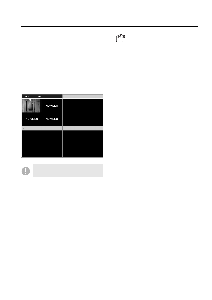
● Multi-view (4x4) layout
(multiple DVRs at the same time)
Live videos from a maximum of four DVRs can
be displayed in each of four sub-panes. Even
if cameras are connected to a single-channel
DVR, videos can be simultaneously viewed
from four cameras (as in a four-view layout) if
the multi-view layout is used.
Moreover, by allocating the videos from a
4-channel DVR, a maximum of 16 sub-panes
(4-channels x 4 sub-panes) can be viewed.
If you are using VA-SW8000LITE, you
cannot access the multi-view layout.
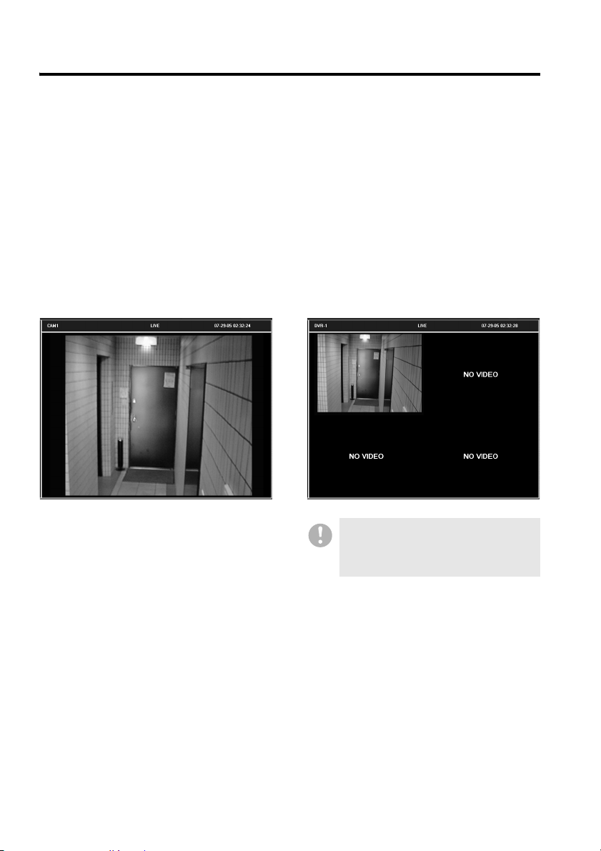
Whichever layout you use, no video
stream is displayed and a black
placeholder with a specific message
appears instead, in the following
situations:
•
The specified channels carries no input
signal:
“VIDEO LOSS”
•
The video is masked:
“MASK”
• No camera is connected:
“NO VIDEO”
(These messages do not appear when
you are connected to a single-channel
DVR .)
English 26
Page 28
Main Window Elements and Their Functions
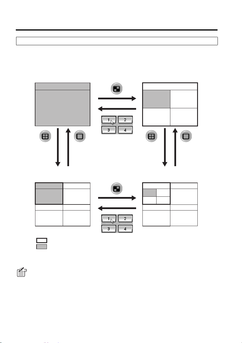
Switching the Viewing pane Layouts
You can switch the viewing pane layouts at any time by clicking a control panel button or
double-clicking the viewing pane.
● When you are connected to a 4-channel DVR
Single-view layout Four-view layout
CH1
DVR-1
CH1
CH2
CH3 CH4
(Or double-click
the viewing
pane. )
Multi-view layout
(The sub-pane assigned to the DVR is
displayed in the single-view layout.)
CH1
(Or double-click
the viewing
pane. )
(Or double-click
the viewing
pane. )
Multi-view layout
(The sub-pane assigned to the DVR is
displayed in the four-view layout.)
DVR- 1
CH1
CH3 CH4
: Sub-pane assigned to the DVR
: Video stream from camera 1 (channel 1) connected to the DVR.
Alternatively, you can select [Display] from the [DVR Operation] menu.
(Or double-click
the viewing
pane. )
CH2
27 English
Page 29
Main Window Elements and Their Functions
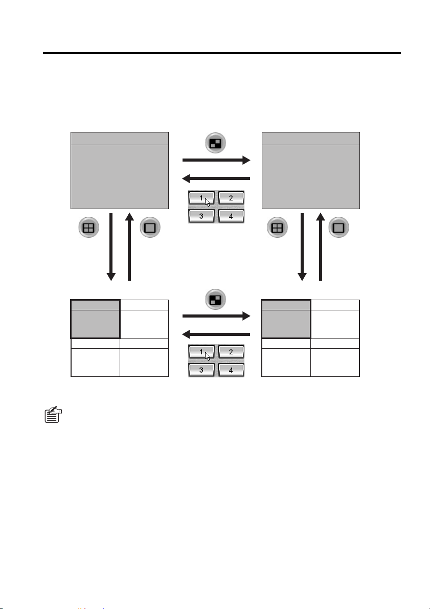
● When you are connected to a single-channel DVR
You can switch the layouts basically the same way as when connected to a 4-channel model;
however, only the single-view and multi-view layouts are actually available because, when you try to
display the four-view layout for a single-channel DVR, the single-view layout is displayed instead.
Single-view layout Single-view layout
(CH1 only) (CH1 only)
DVR-1
DVR-1
(Or double-click
the viewing
pane.)
Multi-view layout Multi-view layout
DVR-1
(Or double-click
the viewing
pane.)
(Or double-click
the viewing
pane.)
DVR-1
(CH1 only) (CH1 only)
Alternatively, you can select [Display] from the [DVR Operation] menu.
(Or double-click
the viewing
pane.)
English 28
Page 30

Main Window Elements and Their Functions
b Title Bar
In live and playback modes, a title bar is placed above each video stream. The title bar provides real-time
information that assists in monitoring work in addition to basic information on the currently displayed video.
1 2 34
● Information on the displayed video
The title bar indicates the following basic information
on the currently displayed video stream:
1 Camera title
The camera title is displayed in the single-view
layout but it is replaced with the DVR name in the
four-view layout and when the DVR is assigned a
four-view sub-pane in the multi-view layouts.
2 Video/operating mode
• LIVE:
• PLAY:
• STILL:
Live video from the currently
monitored camera
Standard playback of recorded video
Still image of the paused video
The PLAY indicator is followed by the
playback speed when you change the
playback speed. (Example: PLAY x 2)
3 Date and time of the video (time stamp)
• In live mode:
• In playback mode:
recording
Current date and time
Date and time of
● Recording status information (4)
The recording status of the connected DVR is
indicated in the middle of the title bar.
• D (red):
Manual recording or timer recording is in
progress.
• C (red):
Timer recording is active. (i.e., timer recording is
either scheduled or ongoing)
The title bar changes its color to indicate the
alarm status.
• Red:
An alarm condition has occurred with the
currently monitored camera (DVR).
• Yel low :
The currently played back video contains
an alarm condition.
● Activating One of the Sub-panes in
the Multi-view Layout
In the multi-view layout, you can select
(activate) one of the four sub-panes by
clicking its title bar; then you can assign a
video stream to the pane or apply a recording
or playback operation.
The title bar, when clicked, changes in color to
indicate it is active.
• Gray: Not selected.
• Blue: Selected.
When alarm video is displayed and you
select sub-pane, its title bar changes
its foreground (text) color as follows:
• If you select a live video sub-pane
(with a red title bar):
Its text (foreground) changes from
black to red.
• If you select a played back video
sub-pane (with a yellow title bar):
Its text (foreground) changes from
black to green.
● Alarm status
29 English
Page 31

Watching Live Video
This section guides you through the basic steps for watching the live video stream from a monitored
camera, and gives description on useful display features.
b Basic Procedures
When you begin routine monitoring work, you should follow these basic steps:
● Log into the system, and switch to
live mode
On the tree list, double-click the camera title
of the camera you want to monitor.
The video stream from your specified camera
is displayed in the single-view layout, and the
title bar indicates the camera title and video
mode (LIVE) as well as the current date and
time.
Double-click
In this example, live video is displayed in the
single-view layout.
● Switch the viewing pane layouts as
needed
Click one of the layout selector buttons on
the control panel.
The single-view layout is initially displayed
when you turn on live mode, but you can
switch to the four-view or multi-view layout as
you like.
Layout selector buttons
● Switching the Video Channels
Click one of the channel selector buttons on
the control panel.
When you are connected to a 4-channel DVR,
the video stream from the camera that
corresponds to your specified channel is
displayed in the single-view layout irrespective
of the layout you have so far been in.
Channel selector buttons
You can switch the channels only when
the camera is connected to a 4-channel
DVR.
● Switch to the Video from Another
DVR
On the tree list, double-click the camera title
of the camera you want to monitor. The
connected DVR is switched to and live video
from the designated camera is displayed.
: Singl e-view layou t
: Sequence (auto switch)
mode
: Four-view layout
: Mult i-view layout
English 30
Page 32

Watching Live Video
● Displaying Video in Each Sub-pane in the Multi-view Layout
Assign video streams from the cameras (DVRs) to be shown in each sub-pane of the multi-view
layout by the following procedure.
You can concurrently monitor four cameras even if your specified cameras are each connected to a
single-channel DVR.
Click on the control panel.
1
The viewing pane switches to the
multi-view layout.
Select one of the four sub-panes by
2
clicking its title bar.
The selected title bar turns blue.
On the tree list, double-click the
3
camera title of the camera you want to
monitor.
The sub-pane displays the live video
from your selected camera.
Assign video streams to the
4
remaining sub-panes.
By repeating steps 2 and 3 above, you
can assign video streams to up to 4
sub-panes.
When connected to a 4-channel DVR,
after selecting the sub-pane by clicking
the title bar, a single-view layout can be
switched to a four-view layout by
conducting one of the following
operations.
• Clicking on the control panel.
• Selecting [DVR Operation] → [Display]
→ [Quad Monitor] on the menu bar.
• Designating the group on the tree list
and selecting “Live” from the context
menu.
13 2 4
Multi-view layout for a single-channel DVR
The same camera video streams or
video streams from cameras connected
to the same DVR cannot be
simultaneously allocated to multiple
sub-panes.
31 English
Multi-view layout for a 4-channel DVR
The screen can display up to 16 sub-panes
(4-channels x 4 sub-panes).
Page 33

Watching Live Video
● Switching from Playback Mode to
Live Mode
Click the Stop Playback button ( ) on
the control panel.
The viewing pane switches to the live video
from the camera that has been selected
during playback.
● Switching from a Sub Window to
Live Mode
When you are working in a sub window
accessible from the Initial Set, DVR
Management, Tool, or another menu, you can
switch to live mode by clicking a layout
selector button or a channel selector
button on the control panel.
English 32
Page 34

Watching Live Video
● How to Listen to the Sound Part in
the Video
Use the sound playback panel on the control
panel. (When in the multi-view layout, specify
the sub-pane for which you want to listen to
the sound by clicking its title bar.)
1
23
1 Sound volume
Drag the control to the left or right to adjust
the sound volume.
2 Turn on/off sound output
Click to toggle between (ON) and
(OFF).
3 Output channel selector
When you are connected to a 4-channel
DVR, specify the set of channels for which
you want to listen to the voice by selecting
the appropriate check box.
● How to Turn Off the Currently
Displayed Video
Click the Cut-Off button ( ) on the control
panel. This turns off the display of video
streams, and black placeholders appear in
place of the video streams.
When you perform this action, you are
disconnected from the DVR in use;
therefore, the video is turned off for all
the cameras connected to that DVR.
• If a channel is feeding a masked
video stream, no sound is outputted
whichever sound output setting is
selected.
• To listen to the sound part in the
video, go to the REC MODE SET tab
of the [DVR Set] window and turn on
[AUDIO RECORDING]. Note that an
error is generated if your computer
has no sound card installed.
33 English
To turn on the video again, double-click the
camera title on the tree list.
About DVR Reconnect Feature
If the live video stream from a camera
is disconnected or otherwise disturbed
for some reason, hold down the [Shift]
key and double-click the camera title
on the tree list. On the confirmation
dialog box that appears, click [Yes] to
reconnect to the DVR.
Page 35

Watching Live Video
b Zoom Mode
When you switch to zoom mode, the displayed video can be enlarged centering on a specified point
on the view.
This feature works in playback mode as well.
Click (1) on the control panel.
1
The button turns red to indicate that you
are now in zoom-in mode.
Click the center point for zoom-in.
2
Point to and click on the desired point on
the view; each time you click the same
center point, the displayed video
enlarges incrementally.
The zoom factor depends on the current
layout.
• When you are viewing the video
from a single-channel or 4-channle
DVR in the four-view layout:
Original size → x2 → x4 → x8 → x12
• When you are viewing the video
from a 4-channel DVR in the
single-view layout:
Original size → x2 → x4 → x6
To zoom out on the video after
3
zoom-in:
Click (
button turns red to indicate that you are
in zoom-out mode.
Each time you click the button, the
displayed video is scaled down
incrementally until it reverts to the
original size.
2) on the control panel. The
If the specified channel is masked,
you cannot use the zoom feature.
2 1
<Original size>
<X4>
<X2>
<X8> <X12>
To revert to the original size:
4
Click one of the layout selector buttons
( ) or channel selector
buttons on the control panel. Then the
viewing pane switches to your selected
layout with the zoom factor reset to the
original size.
English 34
Page 36

Watching Live Video
b Full Screen Mode
When you switch to Full Screen mode, the currently displayed video is maximized to cover the
whole screen with all other user-interface elements, including the menu bar, control panel, and tree
list, hidden from the screen.
This feature works in playback mode as well.
● To switch to Full Screen mode
You can view the video from the currently
selected channel in Full Screen mode by
clicking (
pressing [Ctrl] + [F].
1) on the control panel or
In the single-view layout, if a black
screen with a message saying “VIDEO
LOSS”, “MASK” or “NO VIDEO”
appears, the full screen mode cannot
be switched to.
● Full Screen Operations
Right-clicking on the full screen displays the
context menu, in which the following
operations can be made:
1
1
<Normal mode>
2
3
4
1 Displaying live video stream
2 Playing back
3 Returning to normal mode
4 Switching between show/hide of the
title bar (
●
How to Enlarge the Displayed Video
By left-clicking on the part of the video you
want to enlarge, the video image will be
incrementally enlarged with every click.
2)
Pressing [Ctrl] + [F] in the full screen
mode will also return to the normal mode.
35 English
2
<Full screen mode>
Page 37

Watching Live Video
b Sequential Switching Mode
When you are connected to a 4-channel DVR, you can use Sequential Switching mode to monitor in
turn each of the cameras connected to the four channels.
• This feature is only available when you are connected to a 4-channel DVR.
• You cannot use Sequential Switching mode when you are connected to a single-channel DVR.
View the live video as usual.
1
Select the desired camera from the tree
list, and watch the live video from the
DVR in the single-view or four-view
layout.
Click (one of the layout selector
2
buttons on the control panel).
The software switches to Sequential
Switching mode; it cycles through the
cameras according to the numbers of the
channels they are connected to, and
displays in a single view the video stream
from each camera one after another.
This behavior loops until you exit from
Sequential Switching mode.
To configure the length of intervals
at which the cameras are
switched, use the [Options]
window under the Initial Set
menu. For more information, see
P73.
CH1 CH2
When there is a channel with a
“VIDEO LOSS” placeholder, it is
displayed as it is; however, when
there is a channel with a “MASK”
or “NO VIDEO” placeholder, it is
skipped and not displayed.
To exit from Sequential Switching
3
mode:
Click again to exit from Sequential
Switching mode. You are returned to the
layout you were working in before
switching to Sequential Switching mode.
CH4 CH3
English 36
Page 38

Recording Monitored Video
Live video streamed from a monitored camera can be recorded into the DVR’s internal hard disk.
• You can choose from three recording modes: manual, timer, and alarm.
• The recording mechanism works on the entire DVR. Because of this, when you are connected to
a 4-channel DVR, the video streams from all the four cameras are recorded at the same time,
even if you specify the camera title of one camera.
• To record the sound part in the video as well, go to the REC MODE SET tab of the [DVR Set]
window and turn on [AUDIO RECORDING]. For more information, see P106.
• When you attempt to start manual or timer recording by clicking the corresponding
button, you are presented with a confirmation dialog. Confirm whether or not to start
recording. This dialog is intended to prevent you from inadvertently recording an
unwanted video stream.
b Manual recording (required user access level: ID3/4)
You can manually record live video from monitored cameras.
● Basic Operating Steps
Display live video.
1
When in the multi-view layout, specify the
sub-pane that is displaying the video you
want to record by clicking its title bar.
Click on the control panel.
2
D symbol appears on the title bar, and
A
the DVR starts recording the live video.
Whichever layout is currently applied to
the viewing pane, video streams are
recorded from all the cameras connected
to the DVR.
To stop recording, click on the
3
control panel.
D symbol disappears from the title
The
bar, and the DVR stops recording.
You can manually record live video in
Sequential Switching mode.
You cannot start manual recording
while the DVR is on timer standby or
during timer recording.
1
2 3
37 English
Page 39

Recording Monitored Video
● Recording Video from Multiple DVRs Concurrently
Display the live video streams from multiple DVRs you want to record, and repeat the basic
operating steps (P37).
Once the DVRs start recording live video, they continue the recording process even if they are
disconnected from the DVR Utility Software and their video streams are not displayed in the viewing
pane. Therefore, you can proceed with the recording process with any number of DVRs.
To stop the recording for a DVR, display the live video from that DVR, and then stop the recording.
● Live Video Recording Without Viewing It
When you use manual recording mode to record live video, you can also control the recording
without displaying the live video on the viewing pane. Simply select your desired camera from the
tree list and click the appropriate control button to make the DVR start or stop recording the live
video. This can also be done from within windows accessible from the [DVR Management] and
[Tool] menus.
The broadcast feature allows you to instruct all the DVRs simultaneously to start or stop
recording. For more information, see P70.
English 38
Page 40

Recording Monitored Video
b Timer recording (required user access level: ID3/4)
Timer recording allows you to schedule the automatic recording of live video.
Set up the timer.
1
It is prerequisite that a user with user
access level ID4 should configure the
timer operating conditions using the
TIMER REC SET tab of the [DVR Set]
window. For more information, see P110.
Click (timer button) on the control
2
panel.
The timer is activated and the live video
will be automatically recorded at the
scheduled time.
C symbol is displayed in the title bar
A
when timer recording is on standby.
When timer recording starts, a
symbol appears next to the symbol
mentioned above.
If the [ALARM MODE] is set to “OLY
AL-REC ON TMR” on the REC MODE
SET tab of the [DVR Set] screen, alarm
recording is automatically triggered
when the timer-scheduled time is
reached, so you do not have to click the
timer button.
D
To cancel timer recording:
3
You can cancel scheduled or ongoing
timer recording by clicking again on
the control panel.
C and D symbols disappear and
The
timer recording is canceled.
The broadcast feature allows you to simultaneously turn all the DVRs on or off according to
the timer mechanism. For more information, see P70.
• After you have finished manual or timer recording, you must wait for up to 10 seconds to start
a new recording session.
• After you have changed the DVR’s [PICTURE QUALITY] or [AUDIO RECORDING] setting, you
must wait for up to 6 seconds to start a new manual or timer recording session.
39 English
Page 41

Recording Monitored Video
b Alarm Recording (Required user access level: ID4)
Alarm recording is a feature that automatically records live video when an alarm condition such as
an intrusion has been detected.
The alarm detection works in response to the signal inputs from a motion sensor built into a camera
or an external device (such as a door switch or infrared sensor).
☞To activate alarm recording:
It is prerequisite that a user with user access
level ID4 should configure the trigger condition
for alarm recording on the REC MODE SET
and TITLE MOTION SET tabs of the [DVR
Set] window.
The system automatically starts recording
when an alarm condition is detected, and
stops recording when a predefined time
period elapses. This requires no user
intervention.
A ALARM MODE: (see P108)
Enables/disables alarm recording.
B ALARM DURATION: (see 109)
Determines how long recording should
continue when an alarm condition is
detected.
C ALARM TRIGGER: (see 109)
Set the trigger condition for alarm
recording.
D
MOTION SENSOR: (see P118)
Sets the alarm detection condition that
should be applied to the camera’s internal
motion sensor.
☞To view alarm-recorded video:
You can play back an alarm-recorded video
file the same way as an ordinary recorded
video file. In addition, you can use the search
feature to specify an alarm event and view the
alarm-recorded video associated with the
event. For more information, see P45.
Immediately after alarm recording has
started or immediately after you have
changed DVR’s [PICTURE QUALITY] or
[AUDIO RECORDING] setting, the alarm
recording mechanism is subject to the
following restrictions:
• For up to 4 seconds, it does not
accept any alarm input.
• For up to 6 seconds, it does not start
recording in response to an alarm
input.
A
B
C
Example of settings on REC MODE SET tab
English 40
Page 42

Playing Back Recorded Video
(Required user access level: ID2/3/4)
You can play back recorded video by specifying the source camera (DVR).
Playback does not affect the DVR’s recording operations (timer and alarm).
b Switching to Playback Mode
When you are in live mode and click (one of playback control buttons), the DVR that is
currently streaming video to the viewing pane is switched to playback mode.
☞All layouts support playback
All of the viewing pane layouts (single-view, four-view, and multi-view) support playback;
you can switch to playback mode whichever layout you are currently using. Also, you can
switch the layouts during playback.
• When in the multi-view layout, specify the sub-pane connected to the DVR you want
to switch to playback mode by clicking its title bar.
• By designating a group and selecting the “Play” command on the context menu, the
multi-view layout is automatically switched to.
☞Playback supports all recording modes
The playback mechanism supports all recording modes (manual, timer, and alarm). It
searches for all recorded video files and plays back the video files in chronological order.
When an alarm-recorded video file is being played back, the title bar is displayed with a
red foreground on a yellow background.
☞Where playback starts
When you play back recorded video files for the first time, playback starts at the first video
file. From the second time onward, however, playback resumes at the point where you
ended playback.
Once you have quit the DVR Utility Software, playback starts at the first video file.
☞Operating mode indicator
During playback, the title bar indicates the operating mode and playback speed.
• PLAY: Video is being played back at the original speed. If you change the playback
• STILL: Playback is currently paused and a snapshot (still image) is displayed.
speed, this indicator is followed by the playback speed.
Example: PLAYx2
The playback speed indicated is an approximate value, and it does not accurately
represent the actual speed.
b Returning to Live Video
When you are in playback mode and click (one of playback control buttons), the camera
(DVR) that is currently playing back the video is switched to live mode.
41 English
Page 43

Playing Back Recorded Video (Required user access level: ID2/3/4)
b Working in Playback Mode
To control playback, use the control buttons on the main window.
• In playback mode, you can move the playback point by dragging the scale on the time
scale panel, besides using the playback control buttons.
•
Alternatively, you can use the playback control commands under the [DVR Operation] menu.
• To start playback:
2).
3)/ (1) during playback.
5) during playback.
2).
3), the
5).
4) to stop the playback and
7) on the sound playback
2
1
4
5
7
When you want to listen to any sound
contained in video, be sure to start
playback at the file that contains the
sound. If the file at the playback start
point has no sound recorded, the sound
recorded in any subsequent files may
not be played back.
3
6
Click (
• To fast-forward or fast-reverse the
playback:
Click (
Each time you click one of these buttons,
the playback speed increases
incrementally.
(Speed increments: x2, x7.5, x15, x30,
x180)
• To make a snapshot (still image):
Click (
You can resume normal playback by
clicking (
• To slow the playback:
When you pause playback and click
6), the playback resumes at a x1/8 slow
(
speed. Each time you click (
playback speed increases incrementally; as
you repeat clicking the button, the playback
returns to the original speed, and then
switches to fast-forward mode.
(Speed increments: x1/8, x1/4, x1/2)
• To frame-step the playback:
You can frame-step the playback by
pausing the playback and repeatedly
clicking (
• To stop the playback:
Click (
return to live mode.
• To play back sound:
You can turn on or off the sound output by
clicking (
panel. In playback mode, you can use the
sound playback panel the same way as
when you are in live mode. For more
information, see P33.
English 42
Page 44

Searching for Recorded Video
(Required user access level: ID2/3/4)
You can search for video files recorded in a DVR and play back them.
b Search Modes
You can choose from the following three search modes:
Recording mode
Search Mode
TIME/DATE SEARCH
ALARM LIST
SEARCH
ALARM
SEARCH
ALARM
THUMBNAIL
SEARCH
Manual
recording
Timer
recording
Alarm
recording
FFF
TTF
TTF
Description
Searches for, and plays
back, video files that
match your specified
date and time.
Searches for alarm
events and displays an
alarm list that lets you
locate alarm events of
interest and play back
the video files
associated with them.
Searches for alarm
events and displays a
thumbnail view of
alarm-recorded video
files, from which you can
pick any video files and
play them back.
F: Supported T: Not supported
• You must have user access level ID2 or higher to search for recorded video.
• If the search results include any masked video files, they are not displayed on any of the
preview panes, thumbnail views, or playback panes, and black placeholders with a “MASK”
message appear instead.
Referenced
page
44
46
47
43 English
Page 45

Searching for Recorded Video (Required user access level: ID2/3/4)
b TIME/DATE SEARCH
In this search mode, you can search for, and play back, video files that match your specified date
and time criteria. This mode supports all recorded video files (all recording modes).
To use this search mode, display the live or playback video from the camera (DVR) you want to
search for recorded video (or select your desired camera from the tree list on the main window), and
click the [TIME DATE SEARCH] button on the control panel. Then the [Time Date Search] window
appears:
1
Specify the month/year to which your
1
desired date belongs.
You are presented with a calendar for
your specified month/year.
Specify the desired date.
2
Click a date on the calendar. Your
specified date turns blue.
Specify the desired time.
3
Specify the “hours”, “minutes”, and
“seconds” parts of the time by selecting
the appropriate number from each
drop-down list.
Click .
4
The software starts playing back the
video file(s) that matches your specified
date and time criteria. In this mode, you
can use the same playback controls as in
playback mode.
2
3
4
• By default, the date and time as of
your clicking the [TIME DATE
SEARCH] button (or for played back
video, the date and time included in
the displayed video) is indicated on
the [Time Date Search] window.
• To cancel the search and playback
and close the [Time Date Search]
window, click [Cancel] without
clicking [GO].
If there is no match to your criteria,
the software plays back the video
file newer than and closest to the
specified date and time.
English 44
Page 46

Searching for Recorded Video (Required user access level: ID2/3/4)
b ALARM SEARCH
The alarm search feature searches for alarm events, and displays the search results in the [Alarm
Search] window as either an alarm list or thumbnail view, allowing you to select an alarm event
and play back the associated video file(s).
To use this search mode, click the [ALARM] button on the control panel to navigate to the [Alarm
Search] window.
To switch between the alarm list and thumbnail view, use the [LIST] and [THUMBNAIL] buttons
provided on this window.
The number of alarm event log entries that can be retained on a single hard disk is limited as
follows:
Once the upper limit has been reached, alarm event log entries are added to and deleted from the
hard disk on a first-in first-out basis, and deleted entries no longer appear on the alarm list or
thumbnail view.
• DSR-M810/814: Max. 49,999 entries
• DSR-M804/800: Max. 19,999 entries
You can also access the [Alarm Search] window by selecting the [Alarm Search] option on
the context menu of the tree list. In this case, even if the [LIST] button is not clicked, the DVR
alarm event log is automatically loaded and displayed on the alarm list.
45 English
Page 47

Searching for Recorded Video (Required user access level: ID2/3/4)
1
2
Using the Alarm List to Check and Play Back the Search Results
(ALARM LIST SEARCH)
Channel selector tabs
11
22
3
Click .
1
The alarm list displays, in the
reverse-chronological order, alarm
events that correspond to the channel
currently selected on the tree list.
On the alarm list, click the alarm event
2
whose associated video you want to
play back.
The selected alarm event turns blue.
To preview the video associated with
3
the alarm event, click .
The first frame of the video is displayed
as a still image on the preview pane.
You can use the same procedure (steps
2 and 3 above) to preview the video files
associated with other alarm events.
(You can proceed without previewing the
video files associated with events.)
Once you have located the video of
4
interest, click .
You are brought to the main window, and
your specified video file is played back. In
this mode, you can use the same
playback controls as in playback mode.
4
☞To switch the channels displayed on the
list:
When you are connected to a 4-channel DVR,
you can switch the channels displayed on the
list and preview pane by selecting one of the
tabs.
• ALL:
When you select the ALL tab, the alarm list
displays the alarm events from all the four
channels, and the preview pane displays
the images for all the four channels in a
four-view layout.
• CH1 to CH4:
When you select one of the CH1 to CH4
tabs, the alarm list displays only the alarm
events from the selected channel, and the
preview pane displays the image for the
selected channel in a single-view layout.
☞To change the camera:
To change the camera (DVR) you want to
search for alarms, select a new camera on the
tree list and click ; or double-click
the camera title of a new camera on the tree
list and respond to the confirmation dialog that
is displayed.
English 46
Page 48

Searching for Recorded Video (Required user access level: ID2/3/4)
Using the Thumbnail View to Check and Play Back the Search Results
(ALARM THUMBNAIL SEARCH)
44
11
Click .
1
The Alarm Search window automatically
switches to the layout for alarm
thumbnail search.
Initially, the thumbnails in the thumbnail
view are blank with their title bars
indicating the time/date and channel
number information only.
Click .
2
The software retrieves all alarm video
files from your specified DVR, and
displays their first-frame images in the
thumbnail view in the
reverse-chronological order.
To page up or down the thumbnail
3
view:
A single page of the thumbnail view
contains eight thumbnails. You can
display the previous or next page of the
thumbnail view by clicking or
.
2
53
Click the thumbnail image whose
4
associated video you want to play
back.
The selected title bar is highlighted.
Click .
5
You are brought to the main window, and
your selected video is played back in a
single-view layout. In this mode, you can
use the same playback controls as in
playback mode.
☞To change the camera:
To change the camera (DVR) you want to
search for alarms, select a new camera on the
tree list and click ; or double-click
the camera title of a new camera on the tree
list and respond to the confirmation dialog that
is displayed.
47 English
Page 49

Downloading Recorded Video
Video files recorded in DVRs can be downloaded to computers.
• When you download recorded video, you define the download range by specifying its start and
end points.
• You can download all the video files included within your specified download range; this feature
supports all recording modes (manual, timer, and alarm).
• The download mechanism works on the entire DVR. Because of this, when you are connected to
a 4-channel DVR, the video files originating from all the four cameras are downloaded
concurrently, even if you specify the camera title of one camera.
In the default configuration, the lowest user access level authorized to access the download
mechanism is ID2; however, you can use the [Options] window under the Initial Set menu to raise
the lowest required access level so that users with user access levels ID2 and ID3 cannot access
the download mechanism. For more information, see P73.
b Downloading Procedures
First specify the download range on the main window. Then switch to the download window to
proceed with the download process. The download window allows you to choose from two
download modes: individual and batch.
<Main window>
Specifying the video download range
Define the download range by using the time scale panel and specifying
the start and end points of the range.
<Download window>
Individual download mode
You can specify a video file and download it individually after
configuring and reviewing the download settings.
Batch download mode
You can add video files to the download list so that you can later
batch-download them.
If you want to automate the download process based on timer settings, use the Timer
Download feature accessible from the [Tool] menu. For more information, see P61.
English 48
Page 50

Downloading Recorded Video
b Specifying the Video Download Range
Before you download recorded video, you must define the download range by using the time scale
panel on the main window and specifying the start and end points of the range.
(The following procedure assumes that you set the start point first, but you can also set the end
point prior to the start point.)
1
2 3 4 5
Display played back video.
1
Display the played back video from the camera (DVR) whose video files you want to download.
The viewing pane may be in any of the single-view, four-view, and multi-view layouts; when in
the multi-view layout, however, you must specify the sub-pane connected to the camera (DVR)
whose video files you want to download by clicking its title bar.
Drag the scale (1) to define the start point.
2
When you drag the scale and release it at a position, the playback point moves to that position,
and the playback continues from the new playback point. Repeatedly drag the scale until the
appropriate start point is found. You can advance the time by sliding the scale to the left, or
reverse the time by sliding the scale to the right.
49 English
Advances the time. Reverses the time.
• The playback point moves in increments of the scale’s graduations. Depending on
your desired download range, change the scale unit (DAY/HOUR/MINUTE).
For example, when you set the scale unit to “DAY” and drag the scale, it moves in
increments of one day. Since 30 days are displayed at a time, you can advance or
reverse the playback point by up to 1 month (30 days) with a single drag.
• Instead of dragging the scale, you can double-click a graduation on the time scale to
move the playback point to that position.
Page 51

Downloading Recorded Video
Once you have determined the start point, click [START POINT] (2).
3
The download start point is established at the position where the playback point was residing
when you clicked the [START POINT] button (actually, the date and time values of the time
stamp displayed on the time display at that time are used as the values of the start point). Then
the START POINT button turns red. A green band that indicates the download range appears
on the scale. The left edge of the band is marked with a red line that identifies the start point.
(To reset the start point, click [START POINT] again.)
Click [START POINT].
The start point is established, and a green band appears.
Define the end point.
4
Define the end point in the same procedure as the start point. Since the start point has already
been determined, you can only slide the scale to the left.
Once you have determined the end point, click [END POINT] (3).
5
The download end point is established, and the [END POINT] button turns blue. The right edge
of the band that indicates the download range is marked with a blue line that identifies the end
point.
(To reset the end point, click [END POINT] again.)
Drag to the left to specify the end point.
Click [END POINT].
English 50
Page 52

Downloading Recorded Video
☞To define the start and end points using the mouse:
You can also use the mouse to define the start and end points of the download range. To do
so, follow these steps:
A Point to the target point with the mouse
cursor.
Place the mouse cursor on a scale graduation.
B Click the right mouse button.
A context menu appears.
This menu contains the following
options:
• Download start point
• Download end point
C Select the appropriate option depending
on whether you are going to define the
start or end point.
Your specified point is established as the start or end point; the button color changes as
described in the previous procedure, and the band is marked at its left or right edge.
To preview the video included in the download range:
6
You can play back the video files included in the download range from the start point onward by
clicking [PREVIEW] (
In this mode, you can use the same playback controls as in playback mode.
Click [DOWNLOAD] (5).
7
You are brought to the download window.
The download window lets you finally confirm the download range, specify the download destination,
choose either Individual or Batch download mode, and start the download process.
4) on the panel.
51 English
Once the download window appears, the settings made on the time scale panel are
transferred to the download window, and the time scale panel is initialized. This means that,
when you return to the main window, the time scale appears with neither the start nor the
end point defined.
<Download window>
Page 53

Downloading Recorded Video
b Using the Download Window
1
2
3
4
5
6
7
<Basic controls>
1 DOWNLOAD START/END POINT
Displays the time stamps of the start and end
points of the download range.
2 PREVIEW pane
Displays the still images of the video frames that
correspond to the start point (left) and end point
(right) of the specified download range.
3 FILENAME
Lets you specify the folder and file name of the
download destination.
4 Control buttons
• :
Allows you to start downloading an individual
video file immediately instead of adding them
to the download list.
• :
Allows you to add video files to the download
list (
5) so that you can later batch-download
them.
• :
Displays the still images of the video frames
that correspond to the start and end points of
the specified download range in the PREVIEW
pane.
Basic controls
Download list and
controls
<Download list and controls>
5 Download list
Displays the video files that will be
batch-downloaded. You can add video files to this
list by clicking the [Add] button.
List column headings:
DVRNAME (DVR title), FILE NAME, DATE/TIME
START (start point time stamp), END (end point
time stamp)
6 Total size indicator
Indicates the total combined size of all the files
contained in the Download List.
7 Control buttons
• :
Batch-downloads all the video files contained
in the download list.
• :
Deletes your specified video file(s) from the
download list.
• :
Displays the still images of the video frames
that correspond to the start and end points of
the specified video file in the PREVIEW pane.
English 52
Page 54

Downloading Recorded Video
b Downloading an Individual Video File Using Basic Controls
When the download window is displayed, first prepare for the download process using the basic
controls.
1
2
3
45
Review the download range.
1
By default, the download window
displays the date and time settings
exactly as configured on the time scale
panel on the main window. To modify
these settings, use the spin buttons next
to the [DOWNLOAD START/END
POINT] boxes (
To preview the still images of your
modified start/end points, click
Specify the folder and file name of the
2
download destination.
When a video file is downloaded, the
folder and file name of its destination are
automatically assigned as shown below,
and the path name is displayed in
[FILENAME] (
default destination unless your situation
requires another location.
1).
5).
(
2). You can accept this
53 English
• Default destination folder path:
C:\Program Files\
SANYO\VA-SW8000\
DVR-title_YYYYMMDD_
HHMMSS (start point time stamp)
• Default file name:
DVR-title_ YYYYMMDD_HHMMSS
(start point time stamp)
If you want to change the default
destination, click [Browse..], and specify
new settings on the [Browse for Folder]
dialog.
You cannot specify a removable
drive as the destination.
Page 55

Downloading Recorded Video
Once you are ready for download, use one of the following two options.
A Download an individual
video file
If you want to specify a video file and
download it immediately rather than adding it
to the download list for batch-download, click
This immediately starts the download of your
specified video file.
• The progress of the download is indicated
by the progress bar on the
[DOWNLOADING] dialog; you can also
check the how many kilobytes have already
been downloaded and how long it will take
to complete the download.
(To cancel the download in progress, click
[CANCEL] on the dialog.)
• When the download completes, you are
returned to the window where you were
working before starting the download
process.
(
3).
B
Add video files to the
download list so that they can
be later batch-downloaded
If you want to add a video file to the download
list rather than downloading it immediately,
click (
This adds the video file to the “download list”.
The files contained in the download list can be
later batch-downloaded.
(Proceed to “Adding Video Files to the
Download List for Batch Download”.)
4).
• When a video file is downloaded, two files that share the same file name but are
appended with different extensions (.mp2 and .idx) are created. Because the “.idx” file is
required when playing back downloaded video file and also when checking for
tampering, the two files must always reside in the same folder. For more information, see
P72.
• When the downloaded files are saved in a folder, a playback-dedicated application
named “MP2 Viewer” is also saved. For more information, see P58, P120.
English 54
Page 56

Downloading Recorded Video
b Adding Video Files to the Download List for Batch Download
By clicking the [Add] button among the basic controls, you can add up to 20 video files to the
“download list”. The files contained in the download list can be later batch-downloaded.
This section shows how you can work with the download list.
Download list
4
12 3
☞To remove a file from the list:
On the list, click the file you want to remove. Then click (
from the list.
☞To preview a video file:
On the list, click the file you want to preview. Then click (
images of the video frames that correspond to the start and end points of the specified video file in
the PREVIEW pane.
2). This removes the file
3). This displays the still
☞To check the total combined size of the files contained in the list:
The total size indicator (
download list.
Example:
4) below the list shows the total combined size of all the files contained in the
TOTAL Program:1 Time:0h 9min (248MB / Approx. 0h 3min)
abcd
a Number of files
b Playback time (in minutes)
c File size (in MB)
d Approximate time required for download
(in minutes)
☞To batch-download all the files contained in the list:
Click (
information on the download process, see P54.
1). This batch-downloads all the video files contained in the list. For more
55 English
Page 57

Downloading Recorded Video
b Playing Back Downloaded Video Files
When you want to play back downloaded video files, specify your desired video files on the [Play
List]. You can play back multiple video files in succession.
22
4
1 2 3
3
4
5
1
5
Click [FILE] on the control panel while
1
you are working in the main window.
The [Play List] appears.
Select the file view mode.
2
Specify how to list split files by selecting
either of the following two options.
• GROUP (Default):
This option provides a simplified view
by displaying only the first file in a
group rather than displaying the
details for all of the split files.
(If one group contains more than 100
divided files, subgroups that contain
up to 100 files are created, and the
first file in each subgroup is
displayed.)
• EXPAND:
Provides a detailed view by displaying
the breakdown of all the split files in a
group.
☞What is a “group”?
If a single source video file is larger than
600MB or contains any blank portions or any
video data recorded by the alarm recording
mechanism, the source video file is
automatically split into multiple files and saved
as such while the download process is in
progress.
The DVR Utility Software manages files split
from the same video source file as one
“group”. This scheme makes it easy to play
back download files because the files in a
group are actually split files but can be played
back as if they were a single file. File grouping
occurs on a download by download basis.
File A
(Approx.
1,500 MB)
Download
Whichever view mode you select,
the play list always display entries
grouped by download session.
File-A1
(Approx.
600 MB)
File-A2
(Approx.
600 MB)
Group
File-A3
(Approx.
300 MB)
English 56
Page 58

Downloading Recorded Video
Choose a folder.
3
Click on a folder in the folder list (the left
pane). The files contained in your
selected folder are displayed in the
available files list (the upper half of the
right pane), to which your selected view
mode (either GROUP or EXPAND) is
applied.
List column headings:
FILE NAME, START TIME (recording
start date/time), END TIME (recording
end date/time)
When the view mode is “GROUP”,
the END TIME field shows the
record end date/time for the entire
group.
Click a particular column heading
(FILE NAME, START TIME, END
TIME) to rearrange the files in the
available files list based on the data
contained in that column. The sorting
order toggles between ascending and
descending each time you click the
column heading.
Select files and add them to the play
4
waiting list.
Files contained in the available files list
(the upper half of the right pane) can be
added to the play waiting list (the lower
half). You can add all files or only
selected files to the play waiting list as
shown below:
☞To select individual files and add
them to the play waiting list:
On the available files list, select a
single file you want to play, and then
click (
than one file, repeat this step for all
the remaining files.
1). If you want to play more
☞To add all files to the available files
list:
Click (
All files contained in the available files
list are added to the play waiting list.
3).
57 English
You can add up to 100 video files
to the play waiting list.
Page 59

Downloading Recorded Video
☞To remove a file from the play
waiting list:
On the play waiting list, select a file
you want to remove, and then click
2).
(
☞To remove all entries from the play
waiting list:
Click (
5).
☞To move up or down a file in the
play waiting list:
The files contained in the play waiting
list are played back in the same order
as they are listed.
To move up or down in the play
waiting list, select the file you want to
move, and then click (
You can sort the files in the play
waiting list based on the data
contained in a particular column
by clicking the column heading,
just as you can in the available
files list.
For more information, see P57.
Click .
5
This closes the [Play List] window and
starts continuous playback of the files
contained in the play waiting list.
• You can also start the playback by
double-clicking a file on the play
waiting list. In this case, the playback
starts at the file you double-clicked.
• Once the playback has started, you
can control the playback through the
control panel; however, you cannot
fast-forward or fast-reverse the
playback if you started the playback by
double-clicking a video file on the play
waiting list.
• When split files are played back,
individual files are loaded one after
another.
• To close the [Play List] window and
discard all changes, click [CANCEL].
4).
Playing Back on MP2 Viewer
• Downloaded video files can also be played
back on the dedicated playback application
software “MP2 Viewer” (see P120).
By double-clicking the “MP2 Viewer” file
stored in the downloaded folder, the
program is started. Similar to operations on
this software, designate the video file you
want to play back on the [Play List].
• In cases where the “MP2 Viewer” is
associated as the default player for stored
MP2 files, even if the [Play List] is not
displayed, playback on “MP2 Viewer” can
be automatically started simply by directly
double-clicking the file.
The following two methods of association
are available:
1 When installing this software,
configure in advance on the [File
association] screen (see P8).
File association is configured in the
system folder.
2 Configure [mp2 file associate with
MP2Viewer] on the “MP2 Viewer”
Option menu (see P121).
File association is configured on the
“MP2 Viewer” that is currently
activated.
When "MP2 Viewer" is associated as
the default player for the MP2 file, the
file icon changes as follows.
English 58
Page 60

Saving or Printing Snapshot Images
(Required user access level: ID2/3/4)
When a still (snapshot) image is displayed, you can save it on other storage media or print it at the full size.
● Saving or Printing Images While Playing Back Video from a DVR
When you are playing back recorded video from a networked DVR, you can save or print a still
image through the following procedures.
Display a still image.
1
2
5
44
Display a still image.
1
Click (the pause button) during
playback.
The viewing pane may be in any of the
single-view, four-view, and multi-view
layouts; when in the multi-view layout,
however, you must specify the sub-pane
connected to the camera (DVR) whose
video files you want to download by
clicking its title bar.
Click on the control
2
panel.
You are presented with a window that
allows you to save or print the still image.
The window provides a thumbnail view
that displays all frame images within the
one-second range centered on the frame
you have selected as the still image; this
includes the frames 0.5 second ahead of
and 0.5 second behind your selected still
image as well as all frames in between.
3
The number of frame images actually
displayed depends on the TV system in
use.
• NTSC: 30 images
• PAL : 25 images
To page up or down the thumbnail
3
view:
The thumbnail view spans two pages.
You can page up or down the thumbnail
view using / .
Choose an image.
4
Click an image.
Your selected image is highlighted with a
green frame.
Select [Overlay Time/Date].
5
Select the Overlay Time/Date check box
if you want to overlay the image with the
file name and time stamp.
67
59 English
Page 61

Saving or Printing Snapshot Images (Required user access level: ID2/3/4)
Click the appropriate command
6
button.
Click either of the following two buttons:
• :
This button opens the [Save As]
dialog, and you can save the image as
a JPEG file by specifying the folder
and file name.
• :
This button opens the [Printing]
dialog, and you can print the image at
the full size by specifying the
appropriate print options.
Click [Cancel] to discard all
changes.
Click .
7
This closes the window and brings you
back to the previous window where you
displayed the still image.
• In the default configuration, the
lowest user access level authorized
to save still images is ID2; however,
you can use the [Options] window
under the Initial Set menu to raise the
lowest required access level so that
users with user access levels ID2 and
ID3 cannot access the save
mechanism. For more information,
see P73.
• The button is
disabled unless you display a still
image.
• When you zoom in on an image, you
cannot save the image.
● Saving or Printing Images While
Playing Back a Downloaded File
(see P56)
While playing back a downloaded file, you can
save or print still images basically the same
way as described in the previous section,
except that no thumbnails are displayed.
Display a still image.
1
Click on the control
2
panel.
You are presented with a dialog that
allows you to save or print the still image.
Select the [Overlay Time/Date] check
3
box.
Select the [Overlay Time/Date] check
box if you want to overlay the image with
the file name and time stamp.
Click the appropriate command
4
button.
Depending on whether you want to save
or print the still image, select either
print still images, just as you can while
playing back video from a DVR.
or . You can save or
English 60
Page 62

Using the Tool Menu Options
The “Tool” menu provides various options that allow you to use the DVR Utility Software more
effectively and productively.
To access these options, click [Tool] on the menu bar to open the pull-down menu, and then select
your desired option.
If you are using VA-SW8000LITE, you cannot access the “Tool” menu.
b Timer Download (required user access level: ID2/3/4)
You can automate downloads. To do so, define the download range (by specifying the start and end
points) on a DVR by DVR basis, and set up a timer schedule. The video file within the range will then
be automatically downloaded when the preset time is reached.
You can define up to eight timer schedules for one DVR.
In the default configuration, the lowest user access level authorized to download video files is
ID2; however, you can use the Options window under the Initial Set menu to raise the lowest
required access level so that users with user access levels ID2 and ID3 cannot access the
download mechanism. For more information, see P73.
● Window Elements and Their Functions
1
2
3
4
7 8 9 F G
5
61 English
6
H
I
Page 63

Using the Tool Menu Options
1 SCHEDULE
Specify the date of the week and the time
at which to start the download.
The date and time specified here are
applied as common settings to this window.
• To specify the date of week to
schedule the download:
From the [WEEK] drop-down list, select
SUN, MON, TUE, WED, THU, FRI, or
SAT.
• To schedule the download to occur at
the same time every day:
From the [WEEK] drop-down list, select
“DLY”.
2 FOLDER PATH
Click [Browse..] and specify the destination
folder.
The destination specified here is applied as
a common setting to this window.
You cannot specify a removable
drive, but you can specify a network
drive, as the destination.
3 DISK SPACE
Indicates the free disk space on the
destination drive.
4 TOTAL NUMBER OF ITEMS
Displays the total number of timer
download schedules for the current and
other DVRs.
5 AMOUNT OF OBJECTIVE TIME
Displays the recording/playback time of the
download range including the current and
other DVRs. (Unit: hours)
The displayed length of time is a
total value calculated by simply
summing the lengths of time
between the start and end points of
all the scheduled timer downloads.
Thus it may contain blank frames.
6 SET
You can turn on each schedule by selecting
the corresponding check box in the leftmost
column. Clear the check box for any
schedule you want to suspend. This feature
is useful when you define several timer
schedules and choose from them
depending on your need.
7 NO.
The timer downloads are performed in
ascending order of the timer schedule
numbers.
8 DVR NAME
The title of the DVR to which the timer
schedule is applied.
Since this window is intended to define
timer schedules for a single DVR, the same
DVR name appears in all the rows.
9 FROM WEEK/TIME
Specify the start point of the download
range (day of the week/time).
When you select “DLY” from the
[WEEK] box in the [SCHEDULE]
section, use the [FROM WEEK]
section to specify the download
range start point.
• PREV:
Causes the download to contain
video data recorded the day before
the download is performed.
• APPT:
Causes the download to contain
video data recorded on the same
day the download is performed;
thus the download range starts at
00:00 on the day and ends
immediately before the download
is performed.
F TO TIME
Specify the end point of the download
range (time).
English 62
Page 64

Using the Tool Menu Options
G STATUS
Displays the latest download results or
current status.
• OK: Download successful
• NG: Download failed
• DL: Download in progress
• –: Download scheduled but not started
Clicking [STATUS] displays the “download
log” that contains the history of downloads.
For more information, see P69.
The “download log” allows you to
retry a failed timer download.
H CHANGES ARE APPLIED TO GROUP
Allows you to apply your defined timer
schedules to the group created in the
[Register DVR] window.
To apply the schedules, select the check
box and then click [Apply].
I Control buttons
These buttons are context-sensitive. Any
buttons unavailable in the current context
are grayed out (disabled).
• :
This button is used to activate the timer
download.
When you click the button, the timer
download is put into standby and will
automatically start when your start point
conditions are met.
The indicator at the top of the control
panel indicates the timer download
status as either “Program (download
scheduled but not started)” or
“Downloading (download in
progress)”.
• :
Cancels all the timer downloads,
including both standby and in-progress
downloads, and resets them to the state
before [Std-by] was clicked.
• :
Cancels all changes that have been
made, and initializes the window.
• :
Applies and saves the changes that have
been made in this window.
To activate the downloads based on your
settings, click [Std-by].
63 English
Page 65

Using the Tool Menu Options
Configuring a Timer Download
To configure a timer download, follow these steps:
Choose a DVR.
1
On the tree list, click the camera title of
the camera connected to your desired
DVR. The title is highlighted in blue, and
the title of the DVR to which the camera
is connected appears in all rows in the
[DVR NAME] section.
If the DVR has any scheduled
download, the date is loaded and
displayed on the window. Modify
the schedule settings as needed.
Define the download start point.
2
In the [SCHEDULE] section, specify the
date of the week and the time at which to
start the download.
When you want to schedule the
download to occur at the same time
every day, select “DLY”.
To override the default destination, click
[Browse..] and select your desired folder
from the browse list. You can also create
a new folder by clicking the [NEW
FOLDER] button on the dialog.
You cannot specify a removable
drive as the destination.
Define the download range by
4
specifying the appropriate date/time.
Depending on what you chose from the
[WEEK] drop-down list in the
[SCHEDULE] section, define by one of
the following procedures:
When specifying the day of the week
to schedule the download:
If you selected a setting that corresponds
to a day of the week (i.e., “SUN” through
“SAT”) from the [WEEK] drop-down list,
use the [FROM WEEK/TIME] section to
specify the start point (day of the week/
time) of the download range, and the [TO
TIME] section to specify the end point
(time).
Specify the destination folder.
3
The folder and file name of its destination
are automatically assigned as shown
below, and the path name is displayed in
[FOLDER PATH]. You can accept this
default destination unless your situation
requires another location.
English 64
Page 66

Using the Tool Menu Options
When schedule the download to occur
every day:
If you selected “DLY” from the [WEEK]
drop-down list, use the [FROM WEEK/
TIME] section to specify whether to
download the video data recorded on the
day before (PREV) or the same day as
(APPT) the download occurs as well as
the start point (time) of the download
range, and the [TO TIME] section to
specify the end point (time).
• PREV:
Causes the download to contain the
video data recorded the day before
the download is performed.
• APPT:
Causes the download to contain the
video data recorded on the same day
as the download is performed; thus
the download range starts at 00:00 on
the day and ends immediately before
the download is performed.
Click .
7
Your schedule settings are applied and
saved.
• If the download range is not
correctly specified, an error
message appears. For more
information, see P66.
• When you make changes and
attempt to switch to another
window without clicking the
[Apply] button, a confirmation
dialog appears. Choose whether
to apply the changes by clicking
the appropriate button on the
confirmation dialog.
Click .
8
The timer download is put into standby
and will automatically start when your
start point conditions are met.
The operating mode indicator at the top
of the control panel indicates the timer
download status as follows:
<Message text>
• Program (displayed in orange):
Timer download scheduled but not
started (standby).
• Downloading (displayed in red):
Timer download in progress.
To add a timer schedule:
5
You can repeat step 4 to define up to
eight timer schedules for a single DVR.
Activate the individual schedules you
6
want to apply.
To activate a timer schedule so that the
timer download is performed as
scheduled, select the check box in the
[SET] section.
65 English
You cannot modify a timer
schedule while the timer download
is in standby or in progress (i.e.,
while the “Program” or
“Downloading” message text is
displayed). You must suspend the
timer download by clicking [Stop]
before you can modify a timer
schedule.
Page 67

Using the Tool Menu Options
Applying Changes to All DVRs
in the Same Group
After you have made changes on this window,
you can apply the new settings to all DVRs
that belong to the same group.
To do so, select the [CHANGES ARE
APPLIED TO GROUP] check box before you
click .
In this context, a “group” means one of
the DVR groups created on the [Register
DVR] window, rather than those created
on the [Edit Tree] window (i.e., the
groups displayed in the tree list). Your
settings will be applied to all DVRs
connected with the cameras that belong
to the group.
Tips on Defining the Download
Range
Use the following tips when you define the
download range:
• The download range must have its start
point earlier than its end point. Otherwise,
an error is generated.
• When you set the end point to “00:00”, the
system assumes 00:00 AM. on the next
day.
For example, you can define a 24-hour
download range that spans all video data
recorded on your selected day of the week
by specifying as follows:
• If you specify the same day of the week for
both the recording date of video data to
download and the date on which to perform
the download (i.e., for both the [FROM
WEEK] drop-down list and [WEEK]
drop-down list in the [SCHEDULE] section),
the system will download the video data
recorded one week before.
• When you select “APPT” from the [FROM
WEEK] drop-down list, make sure that the
download range end point is earlier than
the time at which to start the download.
Otherwise, an error is generated.
Valid:
Download start time: 22:30
Download range: 6:00 thru 22:00
Invalid:
Download start time: 18:00
Download range: 6:00 thru 22:00
English 66
Page 68

Using the Tool Menu Options
How the Timer Download
Mechanism Works
Before using the timer download mechanism,
you should confirm the following points:
• A confirmation dialog appears when the
scheduled download start time is reached.
Choose either of the following two actions
by selecting the appropriate button on the
dialog:
• OK:
Close the window, and start the
scheduled download.
• Cancel:
Cancel all the scheduled downloads
without passing control to the download
mechanism.
If there is no response to the
confirmation dialog within 15
seconds, the system assumes that
the user selects OK, and proceeds
with the download process.
• If the download mechanism cannot find any
video data within a download range, which
is defined by specifying when it starts and
ends, it skips the corresponding timer
schedule and generates an error.
(The error information is written into the
download log so you can review it later.)
• The download process does not start if a
user is connected to any of the affected
DVRs when the download start time is
reached. You should disconnect from all of
the affected DVRs when the download start
time is reached, even if you are currently
viewing live video from the affected DVRs.
• The timer download mechanism does not
operate unless the DVR Utility Software is
up and running with a user logged in. You
should not log out of the system or exit from
the software while any download is in
standby or in progress. (If you do so, a
confirmation dialog appears.)
• If there are multiple download ranges
defined, downloads are performed in the
ascending order of their numbers (1 to 8).
67 English
Page 69

Using the Tool Menu Options
Examples of Timer Download Settings
Weekly schedule example – selecting a setting that corresponds to a day of the week from
the [WEEK] drop-down list in the [SCHEDULE] section
In this example, the system automatically downloads the recorded video data that meets the
following criteria from DVR-1 at 12:00 on every Monday.
1 Recorded within the time range of 1:00 to 10:00 on Sunday.
2 Recorded within the time range from 12:00 to 20:00 on the previous Monday, rather than the
current Monday because the [WEEK] drop-down list in the [SCHEDULE] section and the [FROM
WEEK] drop-down list are both set to Monday.
3 Recorded throughout the 24 hours (00:00 to 00:00) of the previous Tuesday.
1
2
3
Daily setting example – selecting DLY from the [WEEK] drop-down list in the [SCHEDULE] section
In this example, the system automatically downloads the recorded video data that meets the
following criteria from DVR-2 at 20:00 everyday.
1 Recorded within the time range of 4:00 to 18:00 on the day before.
2 Recorded throughout the 24 hours (00:00 to 00:00) of the day before.
3 Recorded within the time range of 4:00 to 18:00 on the same day.
4, 5The download start time (20:00) is earlier than the end point of the download range for the
same day; this is an invalid schedule, so an error is generated when you attempt to activate
it. To correct the error, choose “PREV”, instead of “APPT”, from the [FROM WEEK]
drop-down list; or change the download range end point to a point in time that is earlier than
the time at which to start the download.
1
2
3
4
5
English 68
Page 70

Using the Tool Menu Options
Download Log
You can open the download log by clicking [Status] on the [Timer Download] window. The download
log shows the detailed download history for each DVR.
1
5
1 DOWNLOAD DATE
Indicates when the download started.
2 START TIME
Indicates the start point of the download range.
3 END TIME
Indicates the end point of the download range.
4 RESULT
Indicates whether the download completed
successfully. If not, it indicates why the
download failed.
• COMPLETED:
The download successfully completed.
• NO DATA:
The download failed because no video
data were detected in the specified
download range.
• COMMUNICATION ERROR:
The download failed because of a
communication error.
• CONTROL BUSY:
The download failed because a user was
connected to the affected DVR.
• PC HDD FULL:
The download failed because of
insufficient disk space.
• USER CANCELED:
The download was cancelled because
the [Stop] button was clicked.
2 3 4
• DOWNLOAD TIMEOUT:
The download timed out, failing to
complete before the start time of the next
download.
• DOWNLOAD TIME CHANGED:
The download range was changed
because no video data were found
between the specified start and end
points.
• DUPLICATION ERROR:
The download file name conflicted with
an existing file in the destination folder.
5 Control buttons
• :
This button allows you to run a failed
download immediately.
Select the download you want to run by
clicking the corresponding entry on the
download log, and you are presented
with a window for manually starting the
download. This window is already
populated with all information required
for running the download. You can accept
the defaults and proceed with the
download by clicking [Download].
• :
Clicking this button closes the dialog and
resets the [Status] indicator to “–”.
• :
Clicking this button closes the dialog but
leaves the [Status] indicator intact.
69 English
Page 71

Using the Tool Menu Options
b Broadcast
The Broadcast window contains five commands and allows you to broadcast the commands to all of
the connected DVRs without having to specify individual DVRs as targets.
When broadcasting a command, the system polls the connected DVRs at one-minute intervals;
however, if any DVR fails to respond within 3 minutes, the system assumes that the DVR is not
operating for some reason and displays a communication error message .
1
2
3
4
5
6
1 Ranging Broadcast
When [Broadcast Range] is set to “Apply
authorized accessible DVRs” in
configuration of limit accessible DVRs in
the [User ID] window, accessible broadcast
ranges are listed on pull-down menu, so
the following options are available
(see P94):
• When “All authorized accessible
DVRs” is selected:
Broadcast is possible to all DVR groups
authorized for access.
• When a DVR group is selected:
Transmission is limited to only one
selected group.
2 RECORD
(required user access level: ID3/4)
Broadcasts the Record (manual recording)
command, equivalent to one that can be
executed by clicking the Record button on
the control panel.
You can instruct all the DVRs to
simultaneously start or stop recording
video data by clicking (Start
Recording) or (Stop Recording).
3 TIMER RECORD
(required user access level: ID3/4)
Broadcasts the Timer Recording
command, equivalent to one that can be
executed by clicking the Timer Recording
( ) button on the control panel.
Also, you can click or to have all
the DVRs simultaneously turn on/off their
timer recording mechanisms.
English 70
Page 72

Using the Tool Menu Options
4 MENU UPLOAD
(Required user access level: ID4)
You can simultaneously update the menu
files on all the DVRs by doing the following:
1 Click [Browse..].
A dialog opens that displays a list of
referenced files.
2 Select the menu file you want to
broadcast, and click [Open].
The [FILENAME] box is populated with
your specified file name.
The menu file you plan to broadcast
must be stored on your computer's
hard disk before you can broadcast
it. For more information, see P102.
3 Turn on or off the [COPY TITLE /
MOTION SETTINGS] check box.
This check box lets you choose
whether to broadcast the camera title
and motion sensor settings configured
on the TITLE/MOTION SET tab of the
[DVR Set] window. To broadcast the
information, select the check box.
4Click .
The menu file information is broadcast
to all the DVRs, and they
simultaneously update their menu
information.
5 CLOCK SET (Required user access
level: ID4)
Broadcasts the [Clock Set] command to all
the DVRs, equivalent to using the [Clock
Set] window under the DVR Management
menu.
Clicking instructs all the DVRs to
synchronize their internal clocks with your
computer's internal clock.
6 SYSTEM UPDATE
(Required user access level: ID4)
You can broadcast the [SYSTEM UPDATE]
command, which is equivalent to using the
[System Update] window under the DVR
Management menu, by doing the following.
Note that this broadcasts firmware updates
to all the DVRs.
1 Click [Browse..].
Choose which button to click based on
the model of the connected DVRs.
Types of button:
For DSR-M800, DSR-M804,
DSR-M810, and DSR-M814
When you click the button, a dialog opens
that displays a list of referenced files.
2 Select the firmware file you want to
broadcast, and click [Open].
The boxes that correspond to the
models of the connected DVRs are
populated with your specified file name.
The firmware file you plan to
broadcast must be stored on your
computer’s hard disk before you can
broadcast it.
3Click .
The firmware file information is
broadcast to all the DVRs, and they
simultaneously update their firmware.
• Do not use any other firmware file
than supplied from SANYO; doing so
may possibly damage the DVRs.
• Before you can update the firmware,
the DVR(s) must stop any playback or
recording session and the DVR Utility
Software must display live video.
• The update process takes a few
minutes. Do not turn off the power or
disconnect your computer from the
network while the update process is
in progress.
71 English
Page 73

Using the Tool Menu Options
b Tamper Detection (required user access level: ID2/3/4)
It is possible to appraise whether or not video or date and time information of files downloaded from
DVR to external recording media has been tampered with by the following procedure.
Click [Browse..].
1
A dialog opens that displays a list of
referenced files.
Select the video file you want to check
2
for tampering, and click [Open].
The [FILENAME] box is populated with
your specified file name.
You cannot load a video file (.mp2)
unless it is stored together with the
index file (.idx) of the same file
name in the same folder.
Click .
3
The system starts checking the video file
for any altered frames. During this
process, the progress bar in the dialog
shows the status.
To cancel the process in progress,
click [CANCEL] on the dialog.
• If altered frames are detected:
The [ALTERED] window appears that
lists the time stamps of the altered
frames. You can display any altered
frame by clicking the corresponding
row on the [ALTERED] window.
Click [Previous] or [Next] to
move the selected row up or
down on the [ALTERED]
window and automatically
switch the altered frame.
To display an altered frame, click the
corresponding row.
• If tampering of date and time
information is detected:
The “Found time-stamp is altered.”
message appears in the dialog.
Review the results of tamper
4
detection.
• If no altered frames are detected:
The “No altered frames are found.”
message appears in the dialog.
Tampering of date and time information
can only be detected when the DVR from
which video data was downloaded is
DSR-M810(P)/DSR-M814(P) and the
firmware version is 2.30-00 or higher.
English 72
Page 74

Initial Set Menu
The Initial Set menu provides access to four windows: “Options”, “Tree Edit”, “Register DVR”, and
“User ID”. Using these windows, you can configure basic settings required to operate the system,
including network settings and system preferences. The administrative user should use these
windows to configure initial settings when starting the DVR Utility Software for the first time after
installation.
On the menu bar, click [Initial Set] to open the pull-down menu, and navigate to one of the windows
by clicking the corresponding option.
(Required user access level: ID4)
b [Options] Window
1
2
3
4
5
6
7
8
9
1 LANGUAGE
(default: ENGLISH)
Identifies the display language used
throughout the user interface of the DVR
Utility Software. To change the display
language, select the appropriate radio
button.
Available options:
English, French, Chinese, Spanish,
German
73 English
F
2 TV SYSTEM (default: NTSC)
Choose the video standard (either NTSC or
PAL) depending on the input signal
specifications by selecting the appropriate
radio button.
Available options: NTSC or PAL
Page 75

Initial Set Menu (Required user access level: ID4)
3 PC TYPE/MASTER CONTROL PC
Choose whether to use your computer as
the master computer or a slave computer
by selecting the appropriate radio button.
Available options:
• MASTER (master computer):
Within the system, you can use only one
computer as the master, which is
authorized to register or delete networked
DVRs and perform all operations.
If you have selected the “MASTER”
option, the [MASTER CONTROL PC]
field can be left blank.
• SLAVE (slave computer):
Slave computers are for use by end
users. If you have selected the “SLAVE”
option, you must fill the [MASTER
CONTROL PC] field with the IP address
of the master computer.
• If you have selected the “SLAVE”
option, be sure to fill the
[MASTER CONTROL PC] field;
otherwise, a message “IP
ADDRESS ERROR” appears
when you click the [OK] button,
and your changes are all
discarded.
• User ID and password can be
separately set for the master
computer and the slave
computer. For security purposes,
change all computer passwords
for each user level from the initial
settings (1111 - 4444) without fail.
4 DOWNLOAD AUTHORITY
(default: ID2/ID3)
By selecting or clearing each of the two
check boxes, you can specify whether to
authorize each of user access levels ID2
and ID3 to download video files, define
download timer schedules, and save/print
still images.
Tips on authorization
A user authorized to download video
files can also view all the video files
during the download process and while
working with the downloaded files,
even if the associated channel is
masked so that the video cannot be
displayed on the monitor. Clearing the
check boxes prevents users with user
access levels ID2 and ID3 from viewing
masked images; this feature is useful
when it is critical to ensure the privacy
and confidentiality of masked video.
5 AUTO CLOCK ADJUST TIME
(default: OFF)
This feature automatically synchronizes all
of the connected DVRs with your
computer’s internal clock.
To activate this feature, select the “ON”
radio button, and specify the interval of
auto synchronization.
Available options: 1, 2, 3, 6, 12, 24
(hours)
This feature cannot be configured
during the one-hour period before or
after Summer Time switching.
6 SEQUENCE (default: 1)
When you are connected to a 4-channel
DVR, you can use Sequential Switching
mode to monitor in turn each of the
cameras connected to the four channels.
Here, you can set the switching interval
using the spin button. For more information,
see P36.
Valid range: 1 to 30 (seconds)
English 74
Page 76

Initial Set Menu (Required user access level: ID4)
● Network Extension Mode
By default, the DVR Utility Software
supports up to 1,000 DVRs connected to
the network. If you want to connect more
DVRs to the network, you can activate the
network extension mode, in which you can
connect up to 4,000 DVRs. To do so, follow
these steps:
7 NETWORK INTERFACE CARD (NIC)
This drop-down list contains network
interface cards installed in your system.
Choose one network interface card from
the list.
8 USE MORE THAN 1001 DVRS
To switch to the extension mode, select the
“USE” radio button.
• USE:
Sets the number of DVRs to 1,001 or
more (extension mode)
• NO USE (default):
Sets the number of DVRs to within 1,000
9 MAX NUMBER OF UNITS
Once you have activated the extension
mode (by selecting USE), you can specify
the maximum number of DVRs. When you
open the drop-down list, it displays several
choices for the number of DVRs that can be
connected based on the value of the
network interface card’s subnet mask.
Choose the most suitable choice.
Subnet mask value
255.255.252.0 Up to 1,000
255.255.248.0 1,001 - 2,000
255.255.240.0 2,001 - 4,000
Number of
DVRs connected
F Control buttons
• :
Before you click [OK], you can cancel
your changes by clicking this button.
• :
Applies and saves your changes.
When you are done, click [OK] to save
your changes.
Some settings do not take effect until
you quit the DVR Utility Software and
reboot the computer.
☞Settings that take effect immediately
when you click [OK]:
• DOWNLOAD AUTHORITY
• AUTO CLOCK ADJUST TIME
• SEQUENCE
☞Settings take effect after the
computer is rebooted:
• LANGUAGE
• TV SYSTEM
• PC TYPE/MASTER CONTROL PC
• NETWORK INTERFACE CARD
• Network extension mode
For the system to correctly operate, one
of the above three subnet mask values
must be chosen.
75 English
Page 77

Initial Set Menu (Required user access level: ID4)
b [Tree Edit] window (editable on the master computer only)
The DVR Utility Software always lets you select cameras and groups from the tree list when you
perform various operations and configurations using windows. The [Tree Edit] window allows you to
edit titles and groups so that they are well-organized and easy to use and customize the tree
branches based on your monitoring needs.
• Although the [Register DVR] window displays the DVR tree list, the tree list you edit here is
intended for end-user windows and displayed on a camera-by-camera basis.
• Similarly, groups you create here are camera groups that are independent from DVR groups.
• You can also access the [Tree Edit] window by selecting the [Tree Edit] option on the context
menu of the tree list.
• This window is editable on the master computer only.
● Window Elements and Their Functions
1
3
2
When you are done, click [OK] to save your changes and update the tree list.
When you make changes and attempt to switch to another window without clicking the
[OK] button, a confirmation dialog appears. Choose whether to apply the changes by
clicking the appropriate button on the confirmation dialog.
English 76
4
Page 78

Initial Set Menu (Required user access level: ID4)
1 Selecting a DVR Group
The drop-down list shows the groups
registered via the [Register DVR] window.
From the list, select one group you want to
edit.
The details of your selected group are
listed in the detail list.
2 Detail list
• CAMERA TITLE:
The titles of the cameras connected to
the DVRs that belong to the group.
At first, the list shows the titles configured
on the part of the DVRs or those
configured on the TITLE/MOTION SET
tab of the [DVR Set] window (for
4-channel models).
When displayed on the tree list,
the camera title’s check box is
checked.
• DVR NAME:
The titles of the DVRs connected with the
cameras.
By default, the list shows the values
configured initially when DVRs are
registered, or DVR titles configured on
the [Register DVR] window.
3 Tree list
Cameras belonging to the selected group
are displayed as a tree list.
All editing of titles and the tree structure is
conducted on the tree.
4 Control buttons
• :
Applies and saves your changes.
• :
Before you click [OK], you can cancel
your changes by clicking this button.
About the tree list hierarchy
Depending on whether the connected DVRs
are single-channel or 4-channel, the tree list
represents the camera(s) as follows:
☞When you are connected to a
single-channel DVR:
The list displays one camera for one DVR.
☞When you are connected to a 4-channel
DVR:
The list displays four cameras for one DVR.
If using commands such as record and
playback that are applicable to individual
DVRs, executing the command to just one of
the four cameras will cause the other three to
automatically follow suit.
77 English
Page 79

Initial Set Menu (Required user access level: ID4)
Editing the Tree List
The context menu that appears when you right-click a camera or group title in the tree list provides
you with various commands for editing the tree list. You can do the following by selecting the
appropriate command:
☞Open or close a tree
The tree list is hierarchical: lower level tree nodes can be opened and closed by clicking the /
buttons on the left.
Alternatively, you can expand or collapse tree nodes by right-clicking on the root node (folder) or a
group node and selecting “Expand/Collapse” from the context menu.
☞Create a group
Right-click on the root node (folder) or a group folder, and select “New Group” from the context
menu.
A new group folder appears at the bottom of the tree list with the default name of “New Group”. You
can give the new group your own name by typing it into the name box. After typing in the group
name, press the [Enter] key to add the new group to the list.
• The name can contain any characters and symbols that can be typed in but its length
must be within 246 half-size characters.
• The list can accommodate up to 4002 groups including the root group.
• You can create up to four hierarchical levels including the root and can place groups on
the second and third levels and cameras on the second to fourth levels.
Move at least one camera to a created group.
If a group contains no cameras, it will be automatically deleted from the tree list when [OK] is
clicked for that group. (Following deletion, a confirmation message will appear.)
English 78
Page 80

Initial Set Menu (Required user access level: ID4)
☞Change a title
Right-click on a camera or group title, and select “Rename” from the context menu.
In the name input box that appears, type in a new name and then press the [Enter] key. The tree list
and detail list are updated to reflect the new name.
The name can contain any characters and symbols that can be typed in but its length must
be within 246 half-size characters.
☞Move
To move a camera from one to another group or move a group to a different position, cut and paste
the camera or group title using the Cut and Paste commands on the context menu. Alternatively,
you can drag and drop a camera or group title to a new position.
• A camera can be placed on any hierarchical level in the tree, even on the top or lower
levels.
• A group can contain another group placed immediately beneath it, but you cannot include
more than two groups in a single tree.
79 English
Page 81

Initial Set Menu (Required user access level: ID4)
☞Duplicate
You can duplicate a camera or group so that it belongs to more than one group. You can also create
two instances of a group and include one of them underneath another group.
To duplicate a camera or group, copy and paste the camera or group title using the Copy and Paste
commands on the context menu.
You cannot add more than one instance of a camera to the same group.
☞Delete
To delete a camera or group from the tree list, select “Delete” from the context menu. On the
confirmation dialog that appears, click [OK].
• When you remove a camera from the tree list, the corresponding check box in the detail
list is cleared.
• If you want to add a previously removed camera to the tree list again, select the camera
on the detail list, and drag and drop it onto the tree list.
• You can delete a group only when the group contains no camera.
• When you remove all instances of a camera from the tree list, the camera title
configured on this window is lost, and the title in the detail list is reset to the
default title.
English 80
Page 82

Initial Set Menu (Required user access level: ID4)
b [Register DVR] window (accessible on the master computer only)
The [Register DVR] window, accessible on the master computer only, allows you to register or
delete DVRs connected to the monitoring network.
Slave computers contact the master computer to obtain the DVR registration information.
• Before you can use the DVR Utility Software, you must register DVRs connected to the network.
When you start up the master computer for the first time, be sure to perform this initial
configuration task.
• The [Register DVR] window displays the tree list and groups intended exclusively for DVR
registration and management purposes. When you edit the tree list and groups actually
displayed on the user interface, you must use the [Tree Edit] window, rather than the [Register
DVR] window. For more information, see P76.
• By default, the DVR Utility Software supports up to 1,000 DVRs connected to the network. If you
want to connect more DVRs to the network, you can use the [Options] window to activate the
network extension mode, in which you can connect up to 4,000 DVRs. For more information,
see P75.
• When you are done, click [OK]. Your changes are saved, and the configuration data is uploaded
to the DVRs.
When you make changes and attempt to switch to another window without clicking the [OK]
button, a confirmation dialog appears. Choose whether to apply the chang es by clicking the
appropriate button on the confirmation dialog.
● Window Elements and Their Functions
4
81 English
1
2
5
6
7
3
Page 83

Initial Set Menu (Required user access level: ID4)
1 IP address configuration mode selector
2 Group name section
3 DVR title section
4 DVR tree list
This tree list displays group nodes (folders)
and DVRs that belong to each group.
When you change or delete the registration
information of a DVR, you can use the tree
list to select the DVR or group.
5 DVR registration list
This list displays the information on the
DVRs that belong to a group selected in the
tree list.
You can also use the registration list to
select the DVR(s) whose registration
information you want to change or delete.
• DVR NAME
• TYPE (model)
• IP ADDR.
• MAC ADDR.
6 Up/down buttons
You can move up or down a group or DVR
in the list by selecting the group or DVR
and then clicking this button.
Alternatively, you can select a DVR
or group on the tree list and drag
and drop it to a new position.
7 Command buttons
• :
Saves your change, and updates the
DVRs with the new settings.
If a group contains no cameras, it will
be automatically deleted from the tree
list when [OK] is clicked for that group.
• Following deletion, a confirmation
message will appear.
• The initially configured
“WORKGROUP” cannot be deleted.
Clicking [OK] will bring up the following
dialog.
Select whether or not to reflect the
contents configured in the [Register
DVR] window on the user screen tree list.
• Yes:
The current tree list is deleted, and a
new tree list reflecting the new
settings is displayed.
• No:
The configured contents are stored,
however, the tree list display remains
the same.
• :
Before you click [OK], you can cancel
your changes by clicking this button.
• :
Remove the registration information of
DVRs or groups.
English 82
Page 84

Initial Set Menu (Required user access level: ID4)
Registering New DVRs
You can register a new DVR by configuring the
DVR's IP address either automatically or
manually.
● Auto configuration mode
Select auto configuration mode on the
1
DVR's NETWORK SET screen.
On the NETWORK SET screen, set
[ADDRESS SET] to “AUTO”.
< NETWORK SET - ADVANCED >
ADDRESS SET : AUTO
DVR NAME : DVR1
IP ADDRESS : 192.168. 0. 1
SUB NET MASK : 255.255.255. 0
(The actual configuration screen differs
depending on the DVR model.)
Select “AUTO” from [TCP/IP ADDR.].
2
This activates the IP address auto
configuration mode.
Click .
3
The system starts creating the
registration list, with the command
buttons on the windows temporarily
disabled.
Press and hold the [STILL] button on
4
the DVR’s front panel.
Hold down the button until the DVR’s
internal beeper chirps twice.
If the beeper outputs an intermittent
beep and then a continuous beep, it
means that the system has failed to
allocate an IP address. Try again after
making sure that the network
connections and configurations are
correct.
Review the registration information
5
displayed on the list.
When the process completes
successfully, an IP address is allocated
to the DVR, and the tree list and
registration list display the following
items.
• GROUP:
A newly registered DVR belongs to the
WORKGROUP group by default (but the
group can be changed).
• DVR NAME:
A newly registered DVR is by default
assigned a title that consists of the last
six digits (XX-XX-XX) of the MAC
address (but the title can be changed).
• TYPE:
The DVR's model is automatically
recognized and displayed.
• IP ADDR.:
The automatically allocated IP address
is displayed.
• MAC ADDR.:
The DVR's own MAC address is
automatically recognized and displayed.
Click again.
6
The command buttons are enabled.
If you have other DVRs you want to
7
register, repeat steps 1 to 6 above for
each of the DVRs.
Editing the Tree List
8
A newly registered DVR is associated
with default title and group, which you
can change as needed.
For more information, see P86.
In auto configuration mode, you
can specify in advance the group
to which the new DVR should
belong. To do so, click the desired
group (or an existing DVR that
belongs to the desired group)
before clicking the
button. This makes the newly
registered DVR belong to your
specified group, rather than the
default group.
Click .
9
Your changes are saved and uploaded to
the DVR.
83 English
Page 85

Initial Set Menu (Required user access level: ID4)
● Manual configuration mode
Manually configure the IP address on
1
the NETWORK SET screen of the DVR.
On NETWORK SET, set [ADDRESS
SET] to “MANUAL”, and configure the IP
address and subnet mask.
< NETWORK SET - ADVANCED >
ADDRESS SET : MANUAL
DVR NAME : DVR1
IP ADDRESS : 192.168. 0. 3
SUB NET MASK : 255.255.255. 0
• The last three digits of the IP
address must be configured
within the range of 001 to 250.
• Make sure that the new IP
address does not conflict with
any existing IP address.
• How to configure the IP address
differs depending on the DVR
model. For more information,
refer to the DVR’s user’s manual.
When you have additional DVRs you
2
want to register, repeat the same
configuration steps for each of them.
Select “MANUAL” from [TCP/IP
3
ADDR].
This activates the IP address manual
configuration mode.
Click .
4
The system starts creating the
registration list, with the command
buttons on the windows temporarily
disabled.
(If you have configured more than one
DVR for registration, they are registered
at once.)
Normally, it takes about 20
seconds to create the list, but it
may take longer (up to 80 seconds)
depending on the subnet mask
setting.
Review the registration information
5
displayed on the list.
When the process completes
successfully, the tree list and registration
list are updated to reflect the registration
information of the new DVR, and the
command buttons are enabled. Items
displayed in the registration list are the
same as in auto configuration mode. For
more information, see P83.
If the new DVR you register in
manual configuration mode has
already been assigned to a group,
that group name is inherited.
Editing the Tree List
6
A newly registered DVR is given a default
title and group, which you can change as
needed.
For more information, see P86.
Click .
7
Your changes are saved and uploaded to
the DVR.
English 84
Page 86

Initial Set Menu (Required user access level: ID4)
☞Using a Registration List in an
Updated Version
If you have updated the DVR Utility
Software from VA-SW800/804/814 to
VA-SW8000, you can configure the system
to use the registration list created in the
previous version. To do so, use the
[Register DVR] window and follow these
steps:
1
Install VA-SW8000.
During the installation process, you are
prompted to choose whether to remove
the old version’s software files; if you
click YES, the files are automatically
removed.
2 On the [Register DVR] window,
select “MANUAL” from [TCP/IP
ADDR].
3
Click the [Create List] button.
After a while, the DVR Utility Software
retrieves currently registered
information from the DVR and displays
it.
4 Click [OK].
The list is registered, and the
registration information is uploaded to
the DVR.
Deregistering a DVR
To deregister a DVR, follow these steps:
Choose a DVR.
1
On the tree list or registration list, select
the DVR you want to deregister. The
selected DVR is highlighted in blue.
Remove the connecting cable.
2
Remove the connecting cable from the
DVR. When you attempt to deregister a
DVR while it is still connected to the
network, an error results.
Click .
3
You are prompted to choose whether to
proceed. Click [Yes] if you are sure to
deregister the DVR.
Your specified DVR is deregistered, and
removed from the tree list and
registration list.
85 English
Page 87

Initial Set Menu (Required user access level: ID4)
Change a DVR Title
A newly registered DVR is by default assigned
a title that consists of the last six digits
(XX-XX-XX) of the MAC address, but you can
change the title through the following steps:
Choose a DVR.
1
On the tree list or registration list, select
the DVR whose title you want to change.
The selected DVR is highlighted in blue.
Type your desired title into the [DVR
2
NAME] box.
A DVR title can contain uppercase letters
and numbers, up to 10 characters in all.
It can also contain these special
characters: - : . /*, and space.
Click .
3
The tree list and registration list are
updated to reflect the new DVR title.
Alternatively, you can type in a new
DVR title by clicking a DVR on the tree
list and then immediately clicking the
DVR’s title part.
Creating, Modifying, or Deleting
a Group
A newly registered DVR belongs to the
“WORKGROUP” group by default, but you can
create new groups or rename existing groups so
that you can monitor the DVRs more effectively.
• WORKGROUP is a built-in group that
cannot be renamed or deleted.
• When you edit the tree list and groups
actually displayed on the user
interface, you must use the [Tree Edit]
window, rather than the [Register
DVR] window.
● To create a new group:
Enter the new group name into the
1
[GROUP NAME] box.
A group name can contain uppercase
letters and numbers, up to 10 characters
in all. It can also contain these special
characters: - : . /*, and space.
Click .
2
The new group is added to the list and
appears as the last group in the list, but
above the built-in “WORKGROUP”
group, which is always displayed at the
bottom of the tree list.
If you have other DVRs whose titles
4
you want to change, repeat steps 1 to
3 above for each of the DVRs.
Click .
5
Your changes are saved and uploaded to
the DVR.
If your entered group conflicts with an
existing group name, a
results.
If you have other groups you want to
3
create, repeat steps 1 to 2 above for
each group.
“duplicate” error
English 86
Page 88

Initial Set Menu (Required user access level: ID4)
To make a DVR belong to a new
4
group:
Select a DVR currently contained in an
existing group, and move it into the new
group by drag and drop.
Move at least one camera to a
created group.
If a group contains no cameras, it
will be automatically deleted from
the tree list when [OK] is clicked
for that group. (Following deletion,
a confirmation message will
appear.)
Click .
5
Your changes are saved and uploaded to
the DVR.
● To rename a group:
Choose a group.
1
On the tree list, select the group you
want to rename. The selected group is
highlighted in blue.
Enter a new name for the group.
2
You can type in a new name by clicking
the group name part immediately after
clicking the group.
● To delete a group
Choose a group.
1
On the tree list or registration list, select
the group you want to delete. The
selected group is highlighted in blue.
Click .
2
Your specified group is removed from the
registration list.
You can delete a group only when
the group contains no DVR. If the
group still contains a DVR(s), move
the DVR(s) into another group
before the deletion.
If you have other groups you want to
3
rename, repeat steps 1 to 2 above for
each group.
Click .
4
Your changes are saved and uploaded to
the DVR.
87 English
Page 89

Initial Set Menu (Required user access level: ID4)
Rearranging Groups and DVRs
You can rearrange the tree list by moving groups and DVRs contained in it.
● To move a group:
Choose a group.
1
On the tree list, select the group you
want to move. The selected group is
highlighted in blue.
Click or .
2
Your selected group moves up or down
(along with any DVRs contained in it).
You can also drag and drop a
group to a new position.
The “WORKGROUP” group is fixed
at the bottom and cannot be
moved.
● To move a DVR:
Choose a DVR.
1
On the tree list, select the DVR you want
to move. The selected DVR is highlighted
in blue.
Click or .
2
Your selected DVR moves up or down.
You can also drag and drop a
DVR to a new position.
When you select the first DVR shown in
a group and click , the DVR
leaves the current group and moves up
into the previous group. Similarly, when
you select the last DVR shown in a
group and click , the DVR
leaves the current group and moves
down into the next group.
English 88
Page 90

Initial Set Menu (Required user access level: ID4)
b [User ID] Window
This window allows you to register or deregister users authorized to log into the system. The DVR
Utility Software supports up to 32 authorized users.
• You must use the master computer to register, change, or deregister a user with user access
level ID4.
• For the default user account with user name ID4, you can only change the password, and
cannot change the user name or user access level or deregister the account.
● Window Elements and Their Functions
1
2
3
5
6
1
USER ID
Enter the user ID that identifies a user on
the network.
2 PA SS WO RD
Enter the password required to
authenticate the user at login time.
3 User access level buttons
Select one of the four user access levels by
clicking the corresponding radio button.
4 User registration list
This box lists the user name and user
access level of each registered user (but
does not display the password for security
reasons).
When you want to change or deregister a
user, select the user from this list.
4
By default, this window displays the
initial settings for user access levels
1 to 4.
5 Control buttons
• :
Changes the registration information of a
registered user.
• :
Registers a new user.
• :
Deregisters a user.
6 DVR access limitation button
Accessible DVR groups and the
broadcasting range can be configured for
each user (see P93).
89 English
Page 91

Initial Set Menu (Required user access level: ID4)
Registering a New User
To register a new user, configure the user ID, password, and user access level through the following steps:
1
5
2
3
44
Enter the user ID into the [USER ID] box.
1
Enter the user name (user ID) that is
used to identify the user on the network.
The user ID can consist of up to 16
characters including letters
(case-sensitive) and numbers. You can
also use these special characters: :./*
The user ID (user name) must be
unique. If your specified user ID is
already in use, a “duplicate”
message appears.
Enter the password into the [PASSWORD]
2
box.
Enter the password that is required to
authenticate the user at login time.
The password can consist of 4 to 16
characters including letters
(case-sensitive) and numbers. You can
also use these special characters: :./*
Choose a user access level.
3
Select one of the four user access levels
by clicking the corresponding radio
button. For more information, see P11.
Available options:
ID1 (Monitoring user), ID2 (Playback user),
ID3 (Recording user), ID4 (Administrative user)
Click .
4
You are prompted to confirm the
password by reentering it.
Reenter the password.
5
Be sure to reenter the new password to the
[NEW] box. This must be identical to the
one you specified in step 2. Then click
[OK].
When the reentered password is correct,
the registration is completed, and the
user registration list is updated with the
newly registered user ID (user name)
and user access level.
An error message appears if your
reentered password does not match the
one you specified. If this is the case,
reenter the correct password.
English 90
Page 92

Initial Set Menu (Required user access level: ID4)
Changing the Registration Information of an Existing User
You can change the user ID, password, or user access level of an existing user. To do so, follow
these steps:
1
2
3
Choose a user.
1
On the user registration list, select the
user whose information you want to
change. The selected user is highlighted
in blue, and the user’s registration
information appears.
Change the registration information.
2
Change the user ID, password, and/or
user access level through the same
steps you follow when registering a new
user.
Click .
3
When you change the user ID and/or
user access level but not the password,
the user registration list is immediately
updated to reflect your changes.
If you change the password, you are
prompted to confirm the password by
reentering it. In this case, proceed to
step 4.
91 English
Enter the current and new passwords.
4
On the dialog, enter the currently defined
password into the [CURRENT] box, and
reenter the new password to the [NEW]
box. The password entered into the
[NEW] box must be identical to the one
you specified in step 2.
If your entered current and new
passwords are correct, the registration
process is completed, and the user
registration list is updated to reflect your
changes.
An error message appears if your
reentered password does not match the
one you specified. If this is the case,
reenter the correct password.
Page 93

Initial Set Menu (Required user access level: ID4)
Deregistering an Existing User
To deregister an existing user, follow these steps:
1
22
Choose a user.
1
On the user registration list, select the
user you want to deregister. The selected
user is highlighted in blue, and the user’s
registration information appears.
Click .
2
You are prompted to choose whether to
proceed. Click [Yes] if you are sure you
want to deregister the user.
Click [OK].
3
Your specified user is deregistered, and
removed from the user registration list.
English 92
Page 94

Initial Set Menu (Required user access level: ID4)
DVR Access Limitation
The following settings can be configured per user.
• Accessible DVR groups
• Broadcasting permission or broadcasting range
To configure the DVR access limitation settings, follow these steps.
1
2
Specify the user.
1
Click the target user from the user
registration list. The user ID and the user
access level are highlighted in blue.
Click [EDIT] for [Limit accessible
2
DVRs].
The [AUTHORIZED DVR ACCESS]
dialog box is displayed.
Configure [Limit accessible DVRs].
3
Select whether to limit the accessible
DVRs or not.
Options:
• All DVRs (default):
DVR access is not limited.
→All DVRs are accessible.
• Limited DVRs:
DVR access is limited.
→Configure the limitations by setting
[Authorized Accessible DVR Group]
(step 4) and [Broadcast Range]
(step 5).
3
4
5
If you select a DVR not authorized for
access from the Tree List when
selecting “Limited DVRs”, a
confirmation dialog box with the
message “Not allowed to access this
camera.” appears.
93 English
Page 95

Initial Set Menu (Required user access level: ID4)
Configure [Authorized Accessible
4
DVR Group] settings.
The DVR groups registered in the
[Register DVR] window accessible from
the Initial Set menu are listed. Selecting
the check box of a group authorizes
access to the group.
Configure [Broadcast Range]
5
settings.
Select the broadcasting range using the
radio buttons.
Concerning the following notes ( )
related to the selected option, a
confirmation message is shown in the
dialog box when the relevant button is
selected. Confirm the contents and click
[OK].
Options:
• Not allowed:
Broadcast operations are not
permitted.
• Apply authorized accessible DVRs:
Broadcast is only possible to the DVR
groups authorized for access in
[Authorized Accessible DVR Group]
(step 4).
→It is also possible to limit the
transmission destination to one
group in configuration of [Ranging
Broadcast] on the [BROADCAST]
window (see P70).
• All DVRs:
Broadcast is possible to all DVRs.
Broadcast is also sent to the DVR
groups not authorized for access in
[Authorized Accessible DVR Group]
(step 4).
You cannot advance to the next step
without configuring the [Broadcast
Range] settings.
The [Broadcast Range] settings cannot
be configured in the following cases.
• When the access level of the target
user is ID1/ID2 (users not
authorized to perform broadcast
operations).
• When the software you are using is
VA-SW8000LITE (not equipped with
broadcast functions).
Click [OK].
6
Saves the DVR access limitation settings
and closes the dialog box.
Broadcast is limited depending on the
DVR model and firmware version.
• DSR-M810(P)/M814(P):
Broadcast is only possible when the
DVR firmware version is 2.20 or
higher.
• DSR-M800(P)/M804(P):
Broadcast to these models is not
possible.
English 94
Page 96

DVR Management Menu
The DVR Management menu, intended for use by an administrative user, provides access to four
windows: Clock Set, System Update, DVR Info, and DVR Set. The [DVR Set] window has seven
tabs, through which you can fine-tune the DVR operating conditions.
On the menu bar, click [DVR Management] to open the pull-down menu, and navigate to one of the
windows by clicking the corresponding option.
The DVR Management menu lets you select a camera from the tree list. Settings configured on each
window are uploaded to the DVR connected with your selected camera.
(Required user access level: ID4)
b [Clock Set] Window
You can set the internal clock of your specified DVR through the following steps:
Choose a camera (DVR).
1
From the tree list, select a camera
connected to the DVR whose internal
clock you want to set. The selected
camera is highlighted in blue.
Choose from two setting modes.
2
Choose one of the two setting modes by
clicking the corresponding radio button.
• AUTO (default):
In this mode, the DVR is automatically
synchronized to your computer's
internal clock.
• MANUAL:
In this mode, you manually set the
DVR's internal clock.
If you have selected “MANUAL”, set
3
the date and time manually.
Use the spin buttons to set the date and
time.
• The date can be configured
within the range of January 1,
2002 to December 31, 2036.
• The actual date format is
determined by the
corresponding Windows
settings.
Click .
4
The DVR’s clock is adjusted based on
the mode you selected.
• To instruct all the connected DVRs
to simultaneously adjust their
internal clocks, use the broadcast
feature available from the Tool
menu. For more information, see
P70.
• To synchronize all connected DVRs
to your computer’s internal clock at
regular intervals, open the [Options]
window from the Initial Set menu,
and configure the [AUTO CLOCK
ADJUST TIME] settings. For more
information, see P74.
95 English
Page 97

DVR Management Menu (Required user access level: ID4)
b [System Update] Window
You can update the firmware of your specified DVR through the following steps:
2
3
Choose a camera (DVR).
1
From the tree list, select a camera
connected to the DVR whose firmware
you want to update. The selected camera
is highlighted in blue.
Specify the new firmware file.
2
Click [Browse..] to open a file list. Locate
and select the new firmware file, and
click the [Open] button.
The [FILENAME] box is populated with
your specified file name.
• The firmware file you plan to broadcast must be stored on your computer’s hard disk before
you can broadcast it.
• Do not use any other firmware file than that supplied from SANYO; doing so may possibly
damage the DVRs.
• Before you can update the firmware, the DVR(s) must stop any playback or recording session
and the DVR Utility Software must display live video.
• The update process takes a few minutes. Do not turn off the power or disconnect your
computer from the network while updating is in progress.
Click .
3
You are prompted to choose whether to
update the firmware. If you click [YES],
the system starts updating the firmware.
Wait until the update process
4
completes.
You are presented with a dialog that
indicates that the update process is in
progress, and a green light flashes.
English 96
Page 98

DVR Management Menu (Required user access level: ID4)
b [DVR Info] Window
This window consists of two tabs that display the information on the target DVR’s configurations and
hard disk status. Also, the window provides a command that initializes the hard disk(s).
You can work with this window as follows:
Choose either of the two tabs.
1
Select one of the two information tabs by clicking the tab index.
Import the information.
2
To import the latest information from the DVR and activate the tab, do the following:
• From the tree list, select a camera, and click the button at the bottom of the
window.
• Alternatively, double-click a camera on the tree list, and click [Yes] on the confirmation
dialog that appears.
You can also access the [DVR Info] window by selecting the [Status] option on the context
menu of the tree list. In this case, the DVR information is automatically loaded without
clicking the [Import] button.
INFORMATION 1 tab
1
1
2
3
4
5
6
7
8
97 English
2
Page 99

DVR Management Menu (Required user access level: ID4)
<DVR information>
1 TITLE on DVR
Camera titles configured on the DVR main
unit or on the TITLE/MOTION SET tab of
the [DVR Set] window (for a 4-channel
DVR).
2 TITLE for display
Camera titles configured for use by the
system, as configured on the [Tree Edit]
window under the Initial Set menu. These
titles are used throughout the DVR Utility
Software user interface.
3 PICTURE QUALITY
Recording quality levels supported by the
DVR (SUPER+, SUPER, HIGH,
STANDARD).
4 ALARM COUNT
Cumulative total number of alarm
recordings.
<Hard disk drive information>
5 DISK1
Total capacity of hard disk 1.
6 DISK2
Total capacity of hard disk 2.
7 MIRRORING (applies when there are
redundant hard disks)
On/off status of mirroring.
8 Initialize HDD button
This command button allows you to
initialize the DVR’s hard disk(s).
You are prompted to choose whether to
proceed. Click [Yes] if you are sure to
initialize the hard disk(s).
• When you initialize a hard disk, all
the data recorded on the disk are
lost. You should therefore store
important data on another storage
medium in advance. For how to
back up the data, refer to the
DVR’s user’s manual.
• When you install an additional
hard disk, be sure to initialize it. In
this case, you cannot selectively
initialize a particular hard disk; all
the installed hard disks are
initialized. For how to install an
additional hard disk, consult your
dealer.
• Take extreme care not to turn off
the power to the DVR during the
initialization.
What is mirroring?
You can create a redundant mirror of a
hard disk by installing an additional
hard disk. This enables “mirroring”, in
which the same video data are
recorded into two identical disks at the
same time.
Mirroring provides a fault tolerance
benefit because, when one of the two
disks has failed resulting in a read/write
error, you can continue to read the
video data with the other disk.
English 98
Page 100

DVR Management Menu (Required user access level: ID4)
INFORMATION 2 tab
1
2
1 USED TIME
Indicates the total operating hours of each
hard disk as well as the total power-on
hours of the DVR.
2 POWER LOSS
Indicates when the most recent power
failure occurred and when it was recovered
as well as the total cumulative number of
power failures.
3 FIRMWARE VERSION
Indicates the version of the DVR’s firmware
(main/sub).
3
4
No firmware version is indicated if
the DVR is DSR-M800 (P).
4 RECORDING TOP/END
Indicates when the first recording session
started and when the last recording
session stopped.
This information is displayed only if
the DVR is DSR-M810 (P)/M814 (P).
99 English
 Loading...