

Sanyo VA-SW800 Instruction Manual

INSTRUCTION MANUAL
DVR Utility Software
VA-SW800

CONTENTS
DVR UTILITY SOFTWARE FEATURES . . . . . 2
ACCESSORIES . . . . . . . . . . . . . . . . . . . . . . . . 2
NETWORK CONFIGURATION . . . . . . . . . . . . 3
SYSTEM REQUIREMENTS. . . . . . . . . . . . . . . 4
TCP/IP SETTINGS. . . . . . . . . . . . . . . . . . . . . . 5
■ For Windows 2000. . . . . . . . . . . . . . . . . . . 5
■ For Windows XP . . . . . . . . . . . . . . . . . . . . 6
INSTALLING THE SOFTWARE . . . . . . . . . . . 7
LOGGING IN/LOGGING OFF/
DISPLAY LANGUAGE SETTING . . . . . . . . . 10
■ User Level . . . . . . . . . . . . . . . . . . . . . . . . 10
■ Logging In . . . . . . . . . . . . . . . . . . . . . . . . 11
■ Logging Off . . . . . . . . . . . . . . . . . . . . . . . 11
■ Display Language Setting . . . . . . . . . . . . 11
BASIC WINDOW FLOWCHART . . . . . . . . . . 12
FUNCTIONS OF EACH MAIN WINDOW
(MONITORING, RECORDING AND PLAYBACK
WINDOW) COMPONENT . . . . . . . . . . . . . . . 13
BASIC NETWORK SETTINGS . . . . . . . . . . . 15
INITIAL SETUP (SETUP WINDOW) . . . . . . . 17
■ SYSTEM SETUP tab. . . . . . . . . . . . . . . . 17
■ REGISTER DVR tab . . . . . . . . . . . . . . . . 19
CLOCK SETTINGS AND SYSTEM UPDATES
(CLOCK & SYSTEM WINDOW) . . . . . . . . . . 22
■ CLOCK SET tab . . . . . . . . . . . . . . . . . . . 22
■ SYSTEM UPDATE tab . . . . . . . . . . . . . . 23
MENU SETTINGS (MENU WINDOW) . . . . . . 24
■ LANGUAGE/D.S. TIME SET tab . . . . . . . 24
■ REC MODE SET tab . . . . . . . . . . . . . . . . 26
■ TIMER REC SET tab . . . . . . . . . . . . . . . . 28
■ HOLIDAY SET tab . . . . . . . . . . . . . . . . . . 30
■ DISPLAY/BUZZER SET tab . . . . . . . . . . 31
■ POWER FAILURE/USED TIME tab . . . . 33
■ INIT HDD tab . . . . . . . . . . . . . . . . . . . . . . 34
BROADCAST TRANSMISSION SETTINGS
(BROADCAST WINDOW) . . . . . . . . . . . . . . . 35
RECORDING IMAGES. . . . . . . . . . . . . . . . . . 37
■ Normal Recording in a Single Screen . . . 37
■ Normal Recording in a
4-screen Split Screen . . . . . . . . . . . . . . . 38
■ Timer Recording . . . . . . . . . . . . . . . . . . . 39
■ Alarm Recording . . . . . . . . . . . . . . . . . . . 39
MONITORING LIVE IMAGES . . . . . . . . . . . . 40
PLAYING BACK RECORDED IMAGES . . . . 41
VIEWING IMAGES IN A 4-SCREEN SPLIT
SCREEN . . . . . . . . . . . . . . . . . . . . . . . . . . . . . 42
SEARCHING . . . . . . . . . . . . . . . . . . . . . . . . . 43
■ Time/date Search . . . . . . . . . . . . . . . . . . 43
■ Alarm Search. . . . . . . . . . . . . . . . . . . . . . 44
■ Alarm Thumbnail Search . . . . . . . . . . . . . 45
SAVING STILL IMAGES . . . . . . . . . . . . . . . . 46
DOWNLOAD . . . . . . . . . . . . . . . . . . . . . . . . . 47
TAMPER DETECTION. . . . . . . . . . . . . . . . . . 49
English
1

DVR UTILITY SOFTWARE FEATURES
This software is a remote monitoring system for digital video recorders (DVR) and computer
terminals that are connected via a network. It includes an extensive range of functions that
are designed to make optimal use of the latest in technology and network features. It can
cater to a wide variety of monitoring needs including ease of operation and system
expandability.
You can create a network monitoring system that is computer-controlled simply by
●
installing the software on a network computer.
Up to four computers can be connected to control up to a maximum of 1000 DVRs.
●
Menu settings and recording and playback operations are just a few of the DVR
●
operations that can be controlled across the network by a computer.
Recording parameters can be set individually for each DVR.
●
DVR images can be monitored in either a single-screen display or a 4-screen split screen
●
display.
The system is provided with complete security features. Users that have access to the
●
system are verified by means of a user ID and password, and four different user levels
(ID1 to ID4) are available, with different operating privileges for each level.
ACCESSORIES
●
CD-R
●
Hardware key (USB type)
Note: The hardware key must be inserted into the USB port in order to use this software.
English
2
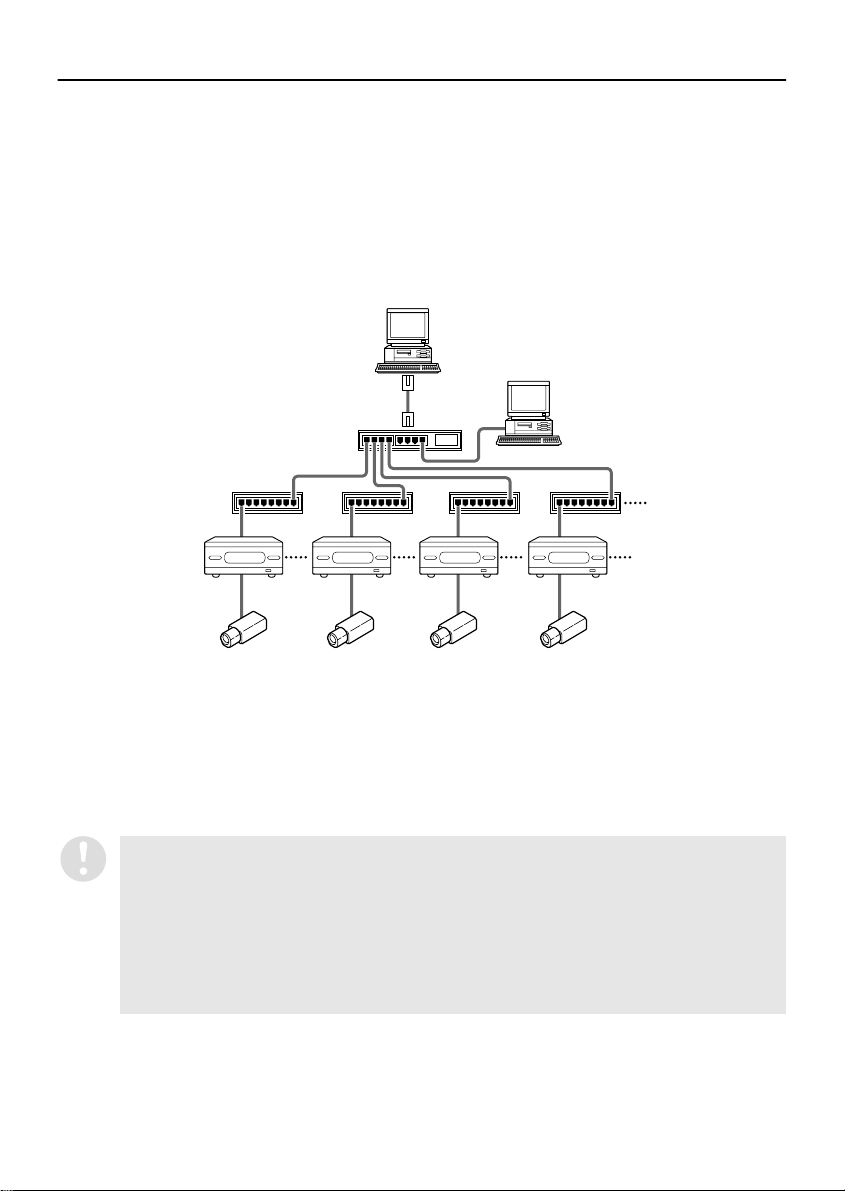
NETWORK CONFIGURATION
This system consists of DVRs, monitoring cameras and computer terminals that are used for
remote monitoring. All devices in the system are connected through a dedicated local area
network (LAN).
● Connection capacity
DVRs: When IP address is set to “AUTO”: Maximum of 1000
Computer terminals: Maximum of four (one master, three slave)
Hub
DVR1 DVR2 DVR3 DVR4
● IP address setting range
Computer terminals: DVRs:
192.168.0.251 ~ 254
192.168.1.251 ~ 254
192.168.2.251 ~ 254
192.168.3.251 ~ 254
When IP address is set to “MANUAL”: Maximum of 250
Master computer
Slave computer
Hub
192.168.0.1 ~ 250
192.168.1.1 ~ 250
192.168.2.1 ~ 250
192.168.3.1 ~ 250
(When the IP address setting is “AUTO”)
English
•
When using the software on a network, carry out the required network settings at
the DVRs first. IP addresses will be assigned automatically, but the “DVR NAME”
and “GROUP” settings can also be changed manually using a computer. (P.20)
•
You should make sure that the TCP/IP settings for the operating system (OS) that
you are using match the computers that are connected to the network. (P.5)
•
Connect the devices to an independent stand-alone network. Furthermore, check
with the network administrator to make sure that the IP addresses that you set do
not conflict with IP addresses that are already in use by the network.
3

SYSTEM REQUIREMENTS
The following environment is required for the operation of this system.
Recommended Minimum Requirement
System IBM PC/AT or Compatible
CPU Pentium 4, 2GHz or faster Pentium III 800MHz
Memory 256MB 128MB
Interface 100Base TX
Display XGA (1024 x 768 pixel), 16-million color or greater
OS Windows
Windows® are trademarks, or registered trademarks of Microsoft Corporation in the United States and/
or other countries.
®
Pentium
States and other countries.
are trademarks or registered trademarks of Intel Corporation or its subsidiaries in the United
®
XP Professional Windows® 2000 Professional (Performance
will drop noticeably when using 4-screen split
screen display.)
English
4
TCP/IP SETTINGS
TCP/IP (Transmission Control Protocol/Internet Protocol) is a standard protocol that is used
for the Internet and intranets. When using the software on a network, you should first
change the TCP/IP settings as required in accordance with the operating systems (OS) of
the various computers that on the network that are to be used.
Select “Internet Protocol (TCP/IP)”
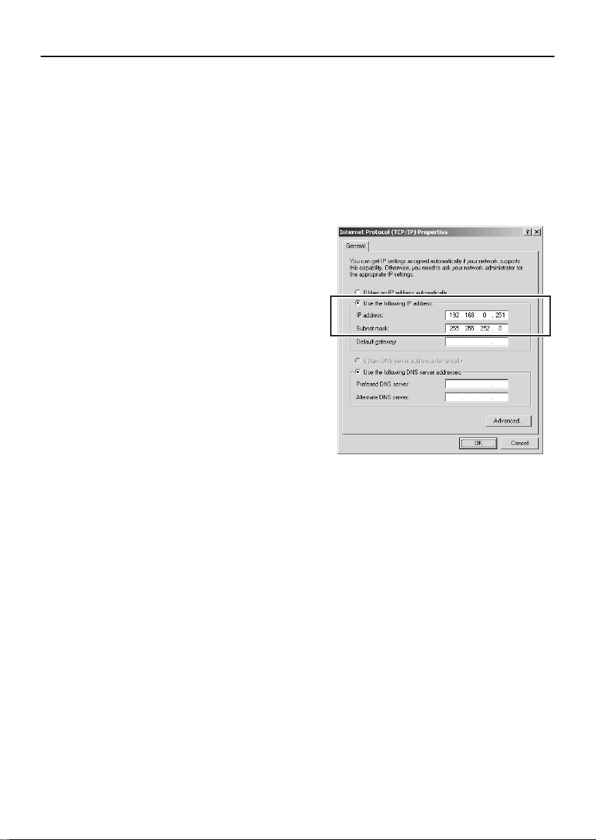
■ For Windows 2000
Double-click the Network and Dial-
1
up Connections icon in the Control
Panel.
Right-click on “Local Area
2
Connection” and then select
Properties from the pop-up menu.
Check that “Internet Protocol (TCP/
3
IP)” appears in the list of
components used by the Ethernet
board that appears in the “Connect
using” box.
If “Internet Protocol (TCP/IP)” does not
appear, click [Install] to install TCP/IP. Refer
to the documentation or Help files for
Windows 2000 for details in installing TCP/
IP.
If “Internet Protocol (TCP/IP)” does not
appear in the list of components even after
you have installed it, click “Start”, select
“Settings”, select “Control Panel”, doubleclick the System icon, and then select the
“Hardware” tab. Check that “Network
Adapter” is enabled in the Device manager.
If “Internet Protocol (TCP/IP)” still does not
appear after “Network Adapter” has been
enabled, refer to the documentation
provided with the Ethernet board.
4
and then click [Properties].
Select “Use the following IP address” and
then type in the IP address and the subnet
mask.
192 168 0
255 255 255
Click [OK], and then click [OK] again
5
in the next dialog box.
If you have changed the Network
6
and Dial-up Connections settings,
restart the computer.
If using the “192.168.0.251” private IP
◆
address, delete the text string that appears in
the “Domain” field.
In the “Internet Protocol (TCP/IP) Properties”
window, click [Advanced] in the General tab
window, click the DNS tab, and then delete the
character string that appears in the “DNS
Suffix” field.
2
0
English
5
TCP/IP SETTINGS
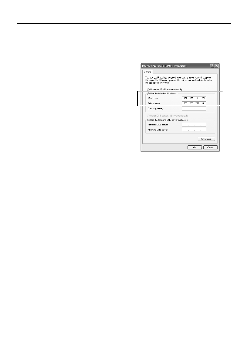
■ For Windows XP
Click the Network Connections icon
1
in the Control Panel.
The “Network and Internet Connections”
window will be displayed.
Click “Local Area Connections”.
2
The “Network Connections” window will be
displayed, and the settings for the LAN card
(Ethernet adapter) being used will appear in
the “LAN or High-Speed Internet” column.
Right-click on the LAN card
3
(Ethernet adapter) being used, and
then select “Properties (R)” from the
pop-up menu.
The “General” tab window in the “Local Area
Connection Properties” window will be
displayed.
Check that “Internet Protocol (TCP/
4
IP)” is selected in the list of
components used by the Ethernet
board that appears in the “This
connection uses the following
items: (O)” box.
If “Internet Protocol (TCP/IP)” is not
selected, select it.
Click [Properties (R)].
5
The “General” tab window in the “Internet
Protocol (TCP/IP) Properties” window will
be displayed.
Select “Use the following IP
6
address: (S)” and then type in the IP
address and the subnet mask.
Check the settings, and then click
7
[OK].
The display will return to the “Local Area
Connection Properties” window.
Click [OK].
8
This completes the TCP/IP settings.
If using Windows XP or 2000, you do not need
◆
to restart the computer even if you have
changed the Network and Internet
Connections settings.
6
English
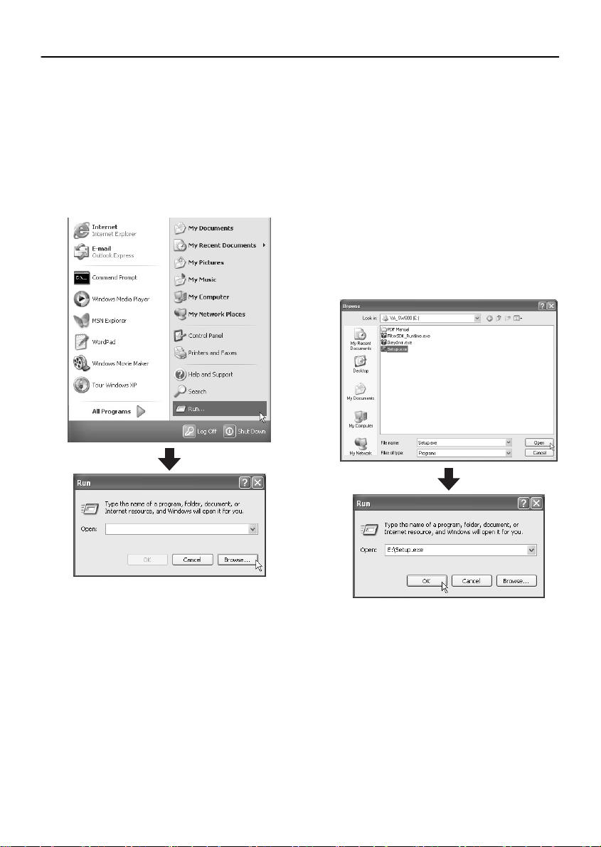
INSTALLING THE SOFTWARE
Install the DVR Utility Software onto a computer that is connected to the network.
Insert the DVR Utility Software CD
1
into the CD-ROM drive of the
computer.
Click the [Start] button on the
2
Desktop and then click “Run...”.
The filename entry box appears.
Type the filename into the box and
3
then click [OK].
If you click [Browse...], a list of files appears.
If you select “Setup.exe” and then click
[Open], the Setup.exe file automatically
appears in the filename entry box.
You can also type the filename into the
filename entry box directly without clicking
[Browse...]. In this case, you also need to
type in the drive path (“E:\” in the example).
After specifying the file, click [OK]. The
“Welcome” window appears.
English
7
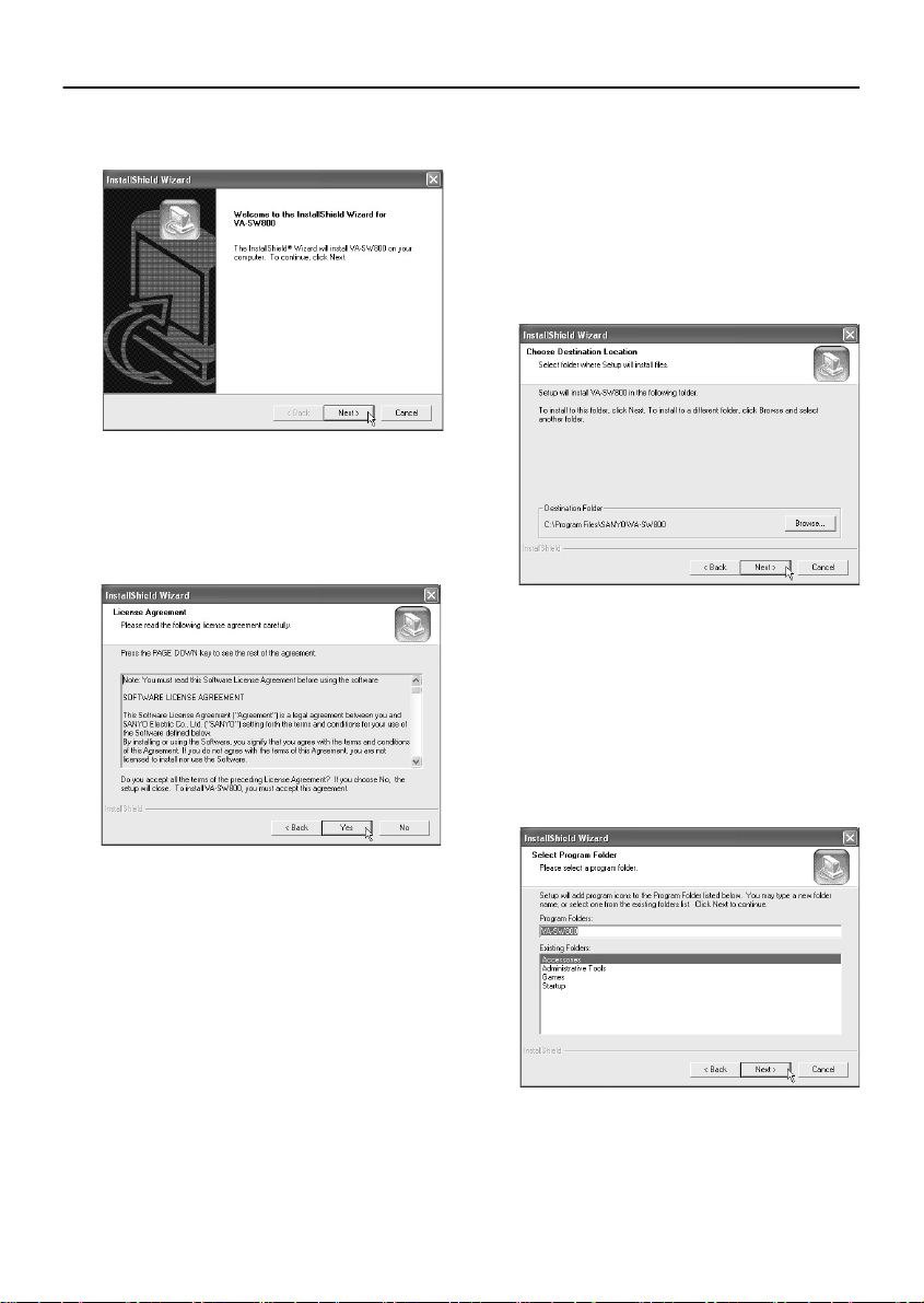
INSTALLING THE SOFTWARE
Click [Next] in the “Welcome”
4
window.
Click [Yes] in the “License
5
Agreement” window.
The License Agreement will be displayed.
Be sure to check the terms of the License
Agreement carefully.
Click [Next] in the “Choose
6
Destination Location” window.
Normally you should accept the default
location without changing it. If you would
like to change the destination folder for
installing the software, type the path to the
folder directly into the box, or click [Browse]
and select the folder to be used for the
installation.
Click [Next] in the “Select Program
7
Folder” window.
This lets you check the program folder
where the program icon will be added.
Normally you should accept the default
folder without changing it. If you would like
to change the program folder, type the
folder name into the box, or select an
existing folder from the list underneath.
8
English
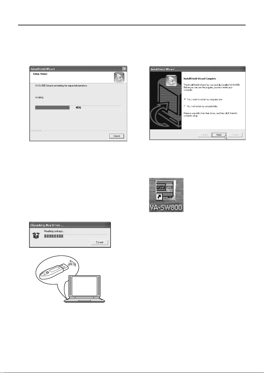
INSTALLING THE SOFTWARE
Installation will begin.
8
Installation of the software will begin, and a
progress bar showing the installation
progress will appear in the “Setup Status”
window.
After this, installation of the
9
hardware key driver starts.
10
Install the hardware key.
Installation of the hardware key driver starts,
and a progress meter shows how far the
installation has progressed. Once the
installation is complete and the
“InstallShield Wizard Complete” window
appears, insert the accessory hardware key
into the USB port of the computer.
11
Restart the computer.
Click [Finish] in the “InstallShield Wizard
Complete” window to restart the computer
automatically. Once the computer has
restarted, installation is then complete.
12
Shortcut icon display
After restarting the computer, a shortcut
icon for the software will appear on the
desktop. Use the icon to start the software.
English
9

LOGGING IN/LOGGING OFF/
DISPLAY LANGUAGE SETTING
The user level for each user on the network can be set to one of four levels. The user level is
verified by means of the user name and password that are entered when the user logs in.
■ User Level
Different operating privileges are set for each user level. The range of operations that are permitted to
be carried out by users depends on their user level. Set the user levels in accordance with the operating
environment.
User Level 1234
User name ID1 ID2 ID3 ID4
Monitoring live images DVR selection, volume adjustment, etc. mmmm
Playback operations mmm
Search operations Time/date search mmm
Alarm search mmm
Alarm thumbnail search mmm
Saving operations Saving still images mmm
Download mmm
Tamper detection operations mmm
Recording operations Normal recording mm
Timer Recording mm
Default settings Language, TV system/master
Clock and system
update settings
Menu settings DVR monitor language, daylight
Broadcast transmission settings mm
Password (default setting) 1111 2222 3333 4444
Operations marked with * are limited to the master computer.
computer settings, changing
passwords, automatic clock settings
Registering and deleting DVRs m*
Clock settings m
Firmware updates m
saving time and external time settings
Recording condition setting m
Timer recording m
Holiday settings m
Display information and warning
buzzer settings
Power failure/Usage time display m
Hard disk information display and
initialization
10
m
m
m
m
English
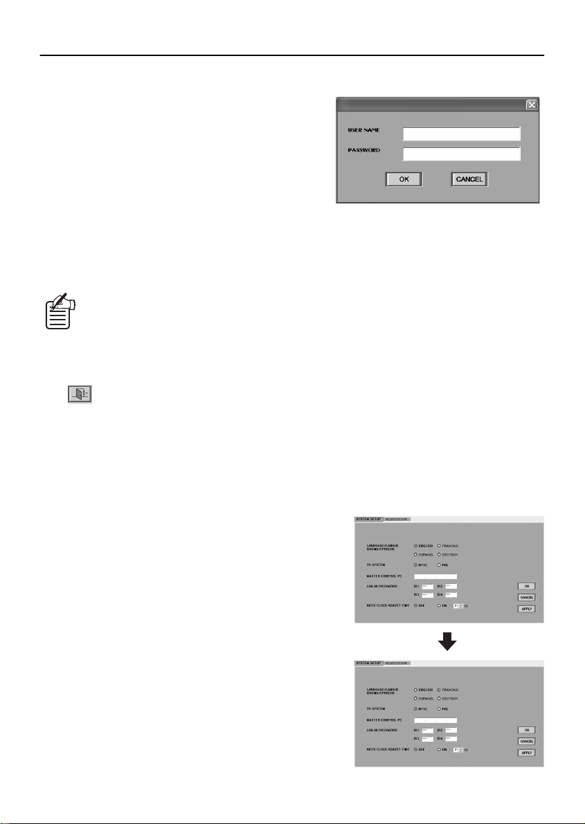
LOGGING IN/LOGGING OFF/DISPLAY LANGUAGE SETTING
■ Logging In
When the software is run, the window for entering the
user name and the password will be displayed. When
logging in, type your user name into the “USER NAME”
box and type the password for verification into the
“PASSWORD” box. Then click [OK].
If the password typed in is incorrect, the window for
entering the user name and the password will be
displayed again and you will need to type the password
in once more. In addition, if you click a button to use an
operation that is not permitted by the user level that
you have logged in at, the window for entering the user name and the password will be displayed again
and you will be required to type in the user name and password corresponding to the user level for that
operation.
After the software has been started, you can change the password in the “SETUP”
window. (P.18)
■ Logging Off
Click on the toolbar to close the connection.
Make sure that you carry out this disconnect operation when exiting the software and closing the
program window.
■ Display Language Setting
This software uses English as its default display language. However, you can use the SYSTEM SETUP
tab in the “SETUP” window to set the display language to any one of the following four languages.
(P.17)
When using the software, first change the display
language setting to the required language.
Available languages:
English, French, Spanish, German
After you have changed the setting, restart the
application. The displays will then appear in the newly
selected language.
English
11
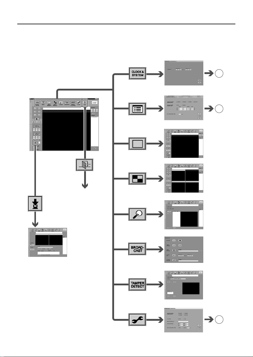
BASIC WINDOW FLOWCHART
When the software is started and a user has logged in, the main window for live image
monitoring and recording/playback is displayed. The software lets you display a variety of
operating windows and setting windows starting from the main window, as shown in the
flowchart diagram below.
B
(P. 15)
CLOCK & SYSTEM window
C
(P. 16)
MENU window
Main window (single screen)
Download window
Click to exit the
software and
close the program
window
12
Main window (4-screen)
SEARCH window
BROADCAST window
TAMPER DETECTION window
A
(P. 15)
SETUP window
English
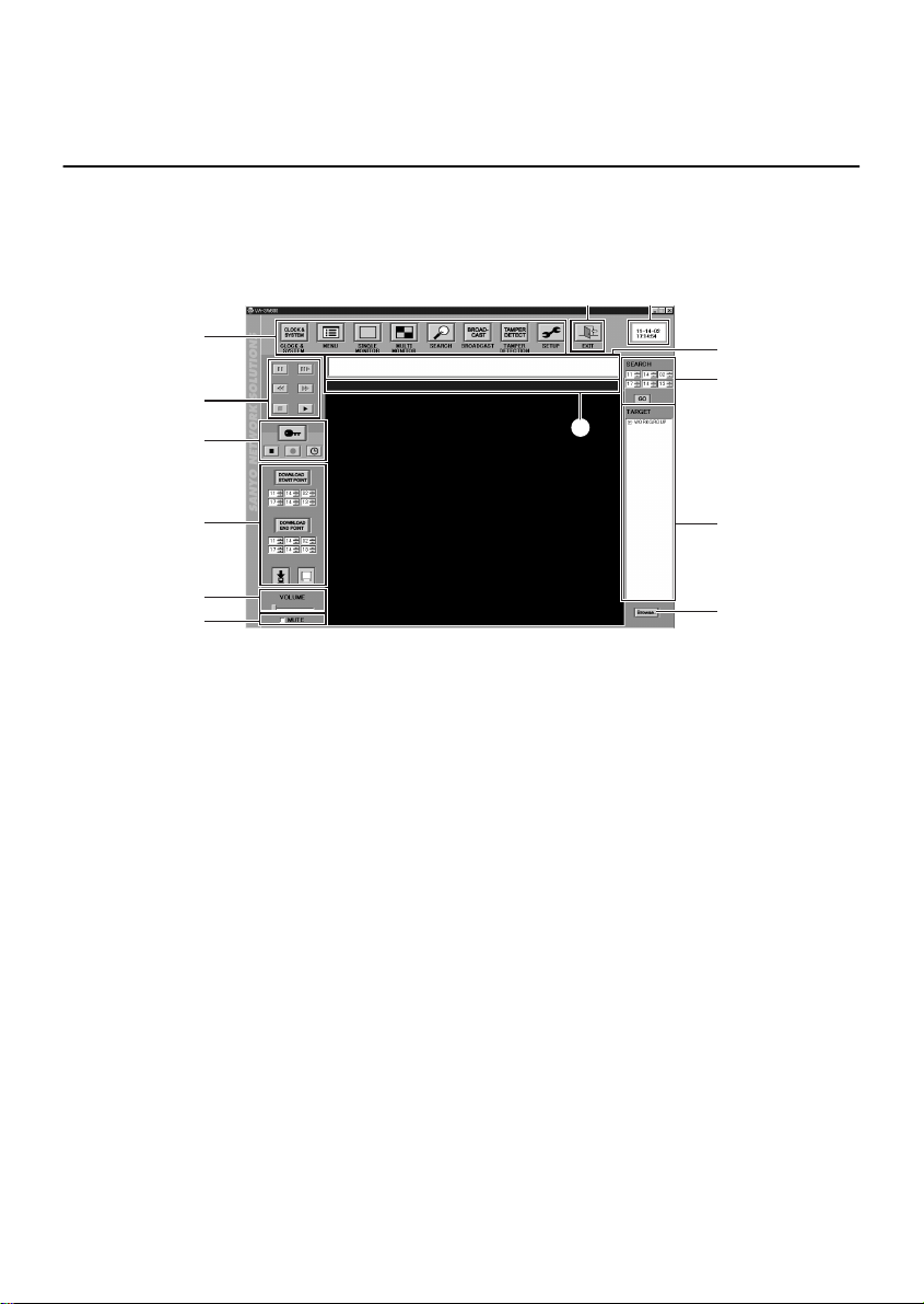
FUNCTIONS OF EACH MAIN WINDOW
(MONITORING, RECORDING AND PLAYBACK
WINDOW) COMPONENT
When the software is started and a user has logged in, the main window for live image
monitoring and recording/playback is displayed as a single screen. Recording and playback
operations can be carried out from this main window, and these operations are possible in both
single-screen (SINGLE MONITOR) and 4-screen split screen (MULTI MONITOR) modes.
2 3
1
5
6
7
8
9
1 Toolbar
This lets you use basic functions and open
different setting windows with a single click. Click
the required icon to use a function or window.
●
CLOCK & SYSTEM (P.22)
This displays the “CLOCK & SYSTEM”
window.
This window is used to set the time and to
update the firmware.
●
MENU (P.24)
This displays the “MENU” window.
This window is used to carry out menu settings
such as setting recording parameters.
●
SINGLE MONITOR (P.37, 40, 41)
This displays images in a single screen. This
is the window that is normally used for
operations such as recording and playback.
●
MULTI MONITOR (P.38, 42)
This displays images in a 4-screen split
screen. This is the window that is normally
used for operations such as recording and
playback.
4
F
I
G
H
●
SEARCH (P.43)
This displays the “ALARM SEARCH” or
“ALARM THUMBNAIL SEARCH” window.
These windows are used to search for alarm
recordings.
●
BROADCAST (P.35)
This displays the “BROADCAST” window.
This window is used for issuing batches of
basic commands such as commands to start
or stop recording to the DVRs that are
connected to the system.
●
TAMPER DETECTION (P.49)
This displays the “TAMPER DETECTION”
window.
This window is used to check for tampering of
images that are being transmitted outside the
system.
●
SETUP (P.17)
This displays the “SETUP” window.
This window is used to make initial program
settings after the software has been installed.
English
13

FUNCTIONS OF EACH MAIN WINDOW (MONITORING, RECORDING AND
PLAYBACK WINDOW) COMPONENT
2 EXIT
Click to exit the software and close the
program window
3 Date and time display
This shows the date and time set by the
computer’s internal clock.
4 Message display window
This shows error or alarm information in order
starting from the earliest that has occurred.
<DVR registration name, time of occurrence,
details of occurrence>
When sending to all DVRs at once, after all
messages have been sent and completion is
normal, <DVR registration name, time of
occurrence, details of occurrence> are
displayed.
Display example:
DVR-3 11-05-02 15:45:40 LIVE ERROR
BROADCAST 11-05-02 15:50:20 DONE
•
The only error messages that are
displayed are system errors
such as communication errors.
The display information is
cleared when you exit the
software, but it is stored in the
log file that is located in the log
sub-folder root folder where the
software was installed.
(Default: C:\Program Files\
SANYO\VA-SW800\log)
5 Playback control panel (P.41)
This is used when playing back recorded
images.
6 Recording control panel (P.37 - 39)
This is used when manually recording images
that are being monitored. In addition, the
control buttons can be locked in order to
prevent accidental recording operations from
being carried out using the recording panel.
7 Saving control panel (P.46, 47)
This is used when saving JPEG images and
downloading images recorded by a DVR into
a computer.
8 Volume adjustment control
(VOLUME)
You can drag this to the left or right to adjust
the volume of the computer sound.
9 Sound mute box (MUTE)
Select this check box if you would like the
sound from the computer to be muted.
F Time/date search (P.43)
This lets you play back recorded images by
specifying a date.
G TARGET (P.40)
The DVR names that are recorded at the
computer are displayed in a list in this
window. You can monitor live images and
play back recorded images from a particular
DVR by selecting that DVR’s name in the list.
H BROWSE
Click this button to specify files that are saved
on a computer drive. Folders and files can be
viewed in a list, and you can specify a file by
typing its filename into the window.
I Title bar
Click the title bar to select a window. The title
bar of a window that is selected in this way
will appear in blue.
In addition, the following information about
the images in the window will also appear in
the title bar.
•
DVR names
•
Recording operation status
b: Normal and timer recording in progress
Ä: Timer recording at standby or in
progress
•
Image mode
LIVE: Live images being monitored
PLAY: Playback images
(The playback speed will also
appear, for example “PLAY X 1/2”.)
STILL: Still image
•
Image date and time
In live mode: Current date and time
In play mode: Recording date and time
14
English
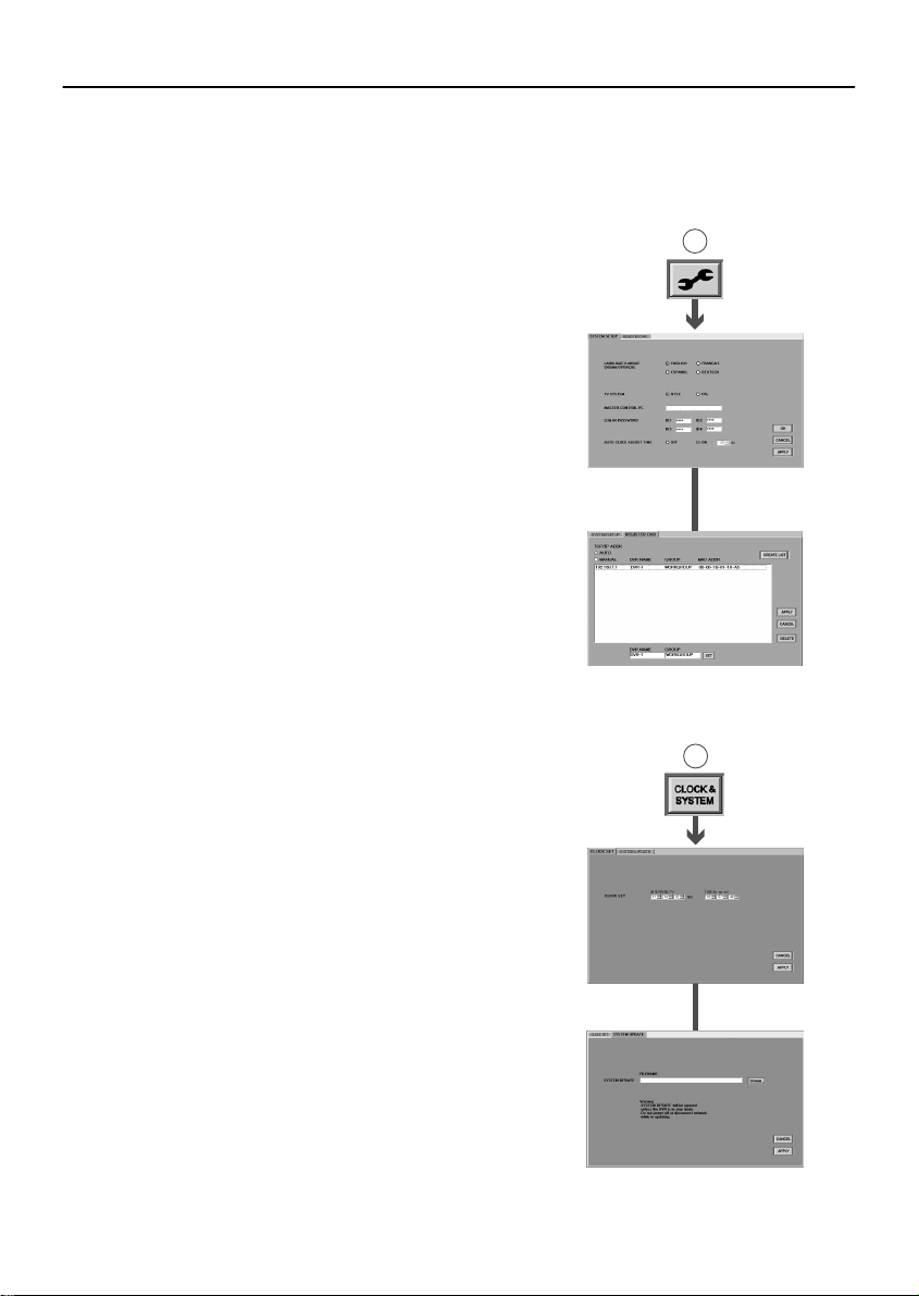
BASIC NETWORK SETTINGS
(User Level: ID4)
In order to use a computer to control DVRs that are on the network, you first need to set
some basic network-related system conditions. Click the icons on the toolbar in the main
window to display the respective setting windows, click on the tab indexes to specify a
particular setting menu, and use these setting menus to make the settings.
■ Initial Setup: SETUP Window (P.17)
This window contains the following two tabs. They are
used to carry out initial settings relating to the network
configuration and the system environment.
1 SYSTEM SETUP tab
Setting the display language
•
Setting the TV format (NTSC/PAL) in accordance with the
•
input signals
Setting the master computer address
•
Setting and changing passwords
•
Setting the automatic adjustment function for DVR clocks
•
2 REGISTER DVR tab (Operation only possible at
master computer)
The options in this tab let you add and remove DVRs on the
network from the DVR registration list. In addition, it can be
used to list the properties of each registered DVR.
■ Clock Settings and System Updates: CLOCK &
SYSTEM Window (P.22)
This window contains the following two tabs. They are
used to set the time and for updating the firmware.
1 CLOCK SET tab
This is used to set the current time for selected DVRs.
A
1SYSTEM SETUP tab
2REGISTER DVR tab
B
2 SYSTEM UPDATE tab
This is used to update the firmware for selected DVRs.
English
1CLOCK SET tab
2SYSTEM UPDATE tab
15
 Loading...